


What Stamping Dies Are and Why They Drive Modern Manufacturing
Defining Stamping Dies and Their Role in Metal Forming
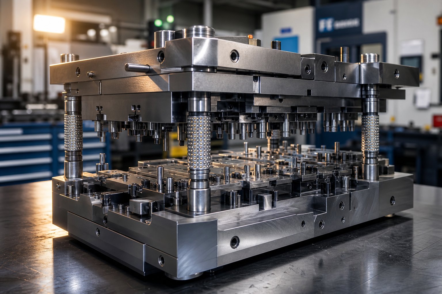
Stamping dies are precision-engineered tool sets installed in stamping presses to cut, bend, and form flat sheet metal into finished components with repeatable accuracy. Each die consists of complementary upper and lower sections that work together under high tonnage to transform raw coil or blank stock into production-ready parts.
So what is dies in manufacturing at a practical level? Think of them as negative molds for metal. Every time the press cycles, the die replicates the same geometry within tight tolerances, whether that means blanking a washer or drawing a deep automotive panel. Metal stamping dies are what make it possible to go from a flat strip of steel to thousands of identical parts per hour without manual intervention.
The sheet metal stamping process relies entirely on die quality. A well-built die controls material flow, manages springback, and maintains dimensional consistency across millions of hits. That combination of speed, precision, and repeatability is exactly why stamping dies manufacturing sits at the heart of high-volume metal forming.
Industries That Depend on Stamping Dies
Stamping dies serve as the backbone for sectors where part volume justifies the tooling investment:
- Automotive - Structural brackets, body panels, transmission components, and airbag housings all rely on automotive stamping dies to meet strict dimensional and strength requirements. Automotive metal stamping alone accounts for a significant share of global die demand.
- Electronics and electrical - Connectors, shielding cans, lead frames, and terminal strips are produced through electrical metal stamping, where micro-tolerances and high cycle counts are standard.
- Appliances and HVAC - Washing machine drums, refrigerator panels, and ductwork components depend on dies and stamping to maintain cost-efficient production at consumer-goods volumes.
- Aerospace and medical - Precision brackets, sensor housings, and surgical instrument blanks demand specialized die designs for exotic alloys and tight tolerances.
Who This Guide Is For
This article is not a glossary entry. It is a mid-to-advanced process guide written for tooling engineers, sourcing managers, and manufacturing leads who need to understand how stamping dies move from raw tool steel to a validated production tool. You will walk through material selection, machining sequences, simulation integration, tryout procedures, and supplier evaluation criteria in the chapters ahead.
The right die configuration, however, is where every project begins, and the options extend well beyond a simple punch-and-die set.
Types of Stamping Dies and How to Choose the Right Configuration
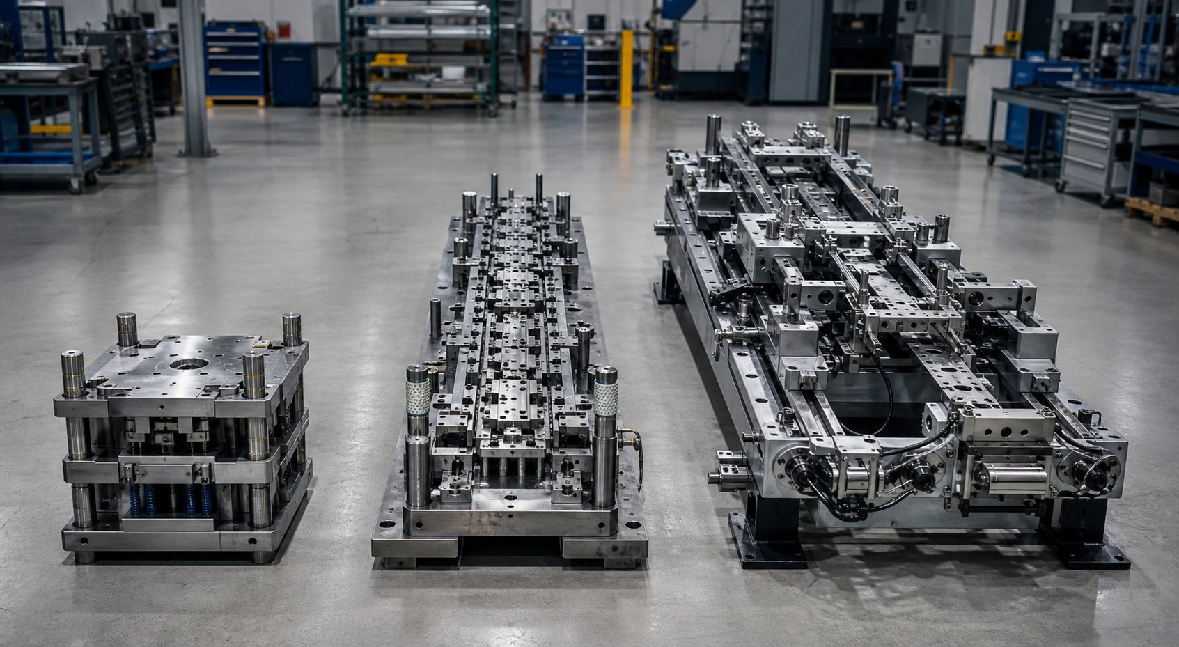
Every stamping project starts with a fundamental question: which die configuration matches the part geometry, production volume, and budget? The types of stamping dies available range from simple single-operation tooling to fully automated multi-station systems, and choosing incorrectly means either overpaying for capability you don't need or bottlenecking production with tooling that can't keep up.
Single-Station Dies for Simple Geometries
A single-station stamping die performs its work at one location in the press. Within this category, you'll encounter three distinct configurations:
- Simple dies - Execute one operation per press stroke: a single blank, pierce, or bend. These are the workhorses for prototyping and low-volume runs where tooling cost must stay minimal.
- Compound dies - Perform multiple cutting operations (blanking and piercing, for example) in a single stroke at one station. They produce tighter positional accuracy between features because everything is cut simultaneously. However, compound dies handle cutting operations only and aren't suited for forming.
- Combination dies - Merge both cutting and forming operations into one stroke. A combination die stamp can blank a part and bend a flange in the same hit, reducing handling steps while keeping tooling investment moderate.
Single-station sheet metal stamping dies make sense when your annual volumes are low to moderate, part geometry is relatively simple, and you need fast lead times. The tradeoff is throughput: each part requires manual or semi-automatic transfer between operations if multiple steps are involved.
Progressive Dies for High-Volume Production
The progressive die stamping process feeds a continuous metal coil through a series of stations within a single die set. Each station performs a specific operation (piercing, notching, forming, trimming) as the strip advances automatically. At the final station, the finished part is cut free from the carrier strip.
What makes die stamping with progressive tooling so efficient? Fully automated coil feeding eliminates part handling between operations, cycle times drop to 1.5-3 seconds per part, and dimensional consistency stays tight across long production runs. Progressive die stamps are the standard choice for high-volume components like electrical connectors, automotive brackets, and appliance hardware where you need millions of identical pieces per year.
The tradeoff is upfront investment. Progressive dies require longer lead times for design and build (typically 4-6 weeks or more), and the tooling cost is significantly higher than single-station alternatives. They also work best for parts that remain attached to the carrier strip throughout forming, which limits maximum part size.
Transfer Dies for Large or Complex Parts
Transfer dies bridge the gap between progressive dies and standalone stations. Like progressive tooling, they move parts through multiple stations in sequence. The key difference: the workpiece is separated from the strip early and physically transferred between stations by mechanical fingers, robots, or shuttle systems.
This makes transfer dies ideal for large structural parts (frames, shells, deep-drawn housings) that are too big or geometrically complex to remain on a carrier strip. They handle parts that require operations from multiple directions or that need re-orientation between stations. Aerospace structural components and automotive body panels frequently rely on transfer die setups.
Choosing the Right Configuration: A Decision Framework
Selecting a stamping die type comes down to matching your project parameters against each configuration's strengths. The table below maps the critical decision criteria:
| Die Type | Typical Production Volume | Part Complexity | Number of Stations | Approximate Lead Time | Relative Tooling Cost |
|---|---|---|---|---|---|
| Simple Die | Low (prototypes to 10K) | Low - single operation | 1 | 3-4 weeks | Low |
| Compound Die | Low to Medium (10K-100K) | Low to Medium - cutting only | 1 | 4-5 weeks | Low to Medium |
| Combination Die | Low to Medium (10K-100K) | Medium - cutting and forming | 1 | 4-6 weeks | Medium |
| Progressive Die | High (100K to millions) | Medium to High - multi-step | 3-20+ | 6-12 weeks | High |
| Transfer Die | Medium to High (50K to millions) | High - large or multi-directional | 4-15+ | 8-16 weeks | High to Very High |
A few practical guidelines emerge from this comparison. If your annual volume exceeds 100,000 parts and geometry fits within strip width constraints, progressive tooling almost always delivers the lowest per-piece cost. For large structural parts or those requiring deep draws, transfer dies justify their premium through capability that progressive setups simply cannot match. And for pilot runs, engineering samples, or annual volumes under 50,000, single-station dies keep capital exposure low while you validate demand.
The die type decision locks in more than just tooling cost. It dictates the material grades your die requires, the machining complexity involved in building it, and the maintenance strategy needed to sustain production quality over time.
Die Material Selection and Surface Treatment Strategies
The material inside your die determines how long it runs, how often it stops for maintenance, and whether it delivers consistent parts at hit 500,000 the same way it did at hit 5,000. Selecting the right stamping die steel is not a catalog exercise. It requires matching the tool material's mechanical properties against the workpiece being formed, the operation type, and the expected production volume.
Tool Steel Grades Mapped to Application Requirements
Five tool steel grades dominate stamping die construction. Each brings a different balance of hardness, toughness, and wear resistance to the table:
- D2 - A high-carbon, high-chromium air-hardening cold work steel (1.4-1.6% C, 11-13% Cr). It achieves 54-61 HRC and delivers excellent wear resistance, making it a standard choice for blanking dies, trim dies, and punches in cold rolled steel stamping and low carbon steel stamping applications. The tradeoff: D2 is less tough than alternatives, so it can chip under high impact loads.
- A2 - Also air-hardening, but with less chromium (4.75-5.5%) and slightly less carbon. A2 runs at 57-62 HRC and offers a balanced combination of wear resistance and moderate toughness. It is commonly used for coining dies, large blanking dies, and long punches where some shock absorption matters.
- S7 - A shock-resistant grade with lower carbon (0.45-0.55%) and chromium (3.0-3.5%). Its working hardness of 48-58 HRC is softer than D2 or A2, but S7 delivers exceptional impact resistance. This makes it the preferred stamping die steel for bending dies, cold forming tools, and any application involving repetitive shock loading.
- DC53 - A modified cold work steel developed as a tougher alternative to D2. DC53 achieves similar hardness (58-62 HRC) but with roughly double the impact toughness, making it a strong candidate for trimming and piercing AHSS grades where D2 fails prematurely from chipping.
- SKD11 - The JIS designation covering essentially the same alloy composition as D2. In practice, SKD11 and D2 are interchangeable, though some suppliers offer refined variants of SKD11 with improved carbide distribution for better fatigue performance in carbon steel progressive stamping applications.
One real-world example illustrates why grade selection matters: a manufacturer forming a 580 MPa ferrite-bainite AHSS with D2 tooling experienced catastrophic tool breakage after just 5,000-7,000 cycles. Switching to a powder metallurgy (PM) tool steel at the same hardness restored tool life to 40,000-50,000 cycles by providing nearly 10x the impact strength through finer, more evenly distributed carbides.
Carbide Components and When They Pay Off
Tungsten carbide (WC-Co) operates in a different performance tier entirely. With hardness levels reaching 88-92 HRA and wear resistance up to 30 times greater than tool steel, carbide stamping dies maintain dimensional precision across millions of cycles. But carbide is brittle, expensive (3-5x the cost of steel tooling), and cannot be repaired with conventional machining.
When does the investment make sense? Consider carbide inserts or solid carbide sections for:
- High-wear stations in progressive dies running multi-million part volumes
- Piercing and blanking abrasive materials like stainless steel or silicon steel laminations
- Applications where tight tolerances must hold without adjustment over extremely long runs
- Forming stations where aluminum stamping dies face galling issues that coatings alone cannot resolve
A practical middle ground: construct the main die body from tough, affordable tool steel and install carbide inserts only at critical high-wear locations. This hybrid approach delivers carbide-level durability where it counts without inflating overall tooling cost.
Surface Coatings That Extend Die Life
The right surface treatment can transform a good steel stamping die into a great one. Coatings reduce friction, resist galling, and protect against adhesive and abrasive wear, all of which directly extend maintenance intervals and improve part surface quality.
Common coating types and their primary benefit:
- TiN (Titanium Nitride) - General-purpose wear resistance; moderate hardness increase with good lubricity for forming mild steel and aluminum.
- TiCN (Titanium Carbonitride) - Higher hardness and lower friction than TiN; suited for cutting and piercing operations on higher-strength sheet.
- TiAlN (Titanium Aluminum Nitride) - Excellent high-temperature performance and oxidation resistance; effective for high-speed blanking of AHSS grades.
- TD/Vanadium Carbide (Thermal Diffusion) - Metallurgically bonded carbide layer with extreme wear resistance; ideal for draw dies and forming operations under high contact pressure.
- Chrome Plating - Traditional low-friction option, but prone to microcracking and not recommended for AHSS applications due to premature failure under high contact stress.
- Ion Nitriding (Plasma Nitriding) - Creates a hard diffusion layer that serves as an excellent substrate preparation before PVD coating; works well for galvanized steel forming where PVD coatings alone may cause zinc buildup.
The application method matters as much as the coating itself. PVD coatings bond physically at lower temperatures (below 500 degrees C), preserving die hardness and minimizing distortion. CVD and TD processes create stronger metallurgical bonds but require temperatures around 1000 degrees C, which can soften the tool steel substrate and necessitate re-hardening. Several global automakers now specify PVD-only coatings for this reason.
How dramatic is the performance difference? In one documented comparison, a chrome-plated tool failed after 50,000 parts, while an ion-nitrided tool with a PVD chromium nitride coating produced over 1.2 million parts from the same AHSS material.
Matching Die Material and Coating to Workpiece Material
The workpiece you're stamping drives the die material and coating decision more than any other single factor. Harder, stronger sheet metals impose proportionally higher loads on tooling surfaces, some AHSS grades approach the hardness of the dies forming them.
| Workpiece Material | Recommended Die Steel | Recommended Coating/Treatment | Key Concern |
|---|---|---|---|
| Mild / Low-Carbon Steel | D2, A2, or DC53 | TiN or ion nitriding | Moderate wear; standard maintenance intervals |
| Stainless Steel | DC53, PM tool steel, or carbide inserts | TiCN, TiAlN (PVD), or TD | Galling and adhesive wear from high work hardening |
| Aluminum | A2, D2 (polished), or carbide inserts | TiN, TiCN, or DLC (diamond-like carbon) | Aluminum adhesion and galling; surface finish critical |
| High-Strength Steel (AHSS, 590 MPa+) | PM tool steel, DC53, or carbide inserts | PVD TiAlN over ion nitrided substrate | Extreme contact loads; chipping and cracking risk |
| Galvanized Steel | D2, DC53 | Ion nitriding (avoid PVD alone) | Zinc adhesion to PVD coatings; powdering at elevated die temps |
Notice the pattern: as workpiece strength climbs, die material must shift from conventional tool steels toward PM grades or carbide, and coatings move from optional to mandatory. For steel stamping dies running low carbon steel stamping operations, a properly heat-treated D2 with basic nitriding may last hundreds of thousands of cycles. That same D2 die forming a 980 MPa dual-phase steel without upgraded material and coatings may fail catastrophically within weeks.
The investment in advanced materials and coatings is not about overengineering. It is about matching the die to the demands of the workpiece so that maintenance costs, scrap rates, and unplanned downtime stay under control across the full production life of the tool. That production life, however, depends equally on how accurately the die is built, which brings us to the manufacturing process itself.
Step-by-Step Stamping Die Manufacturing Process
Selecting the right material and coating is only half the equation. A die built from premium PM tool steel with a PVD TiAlN coating will still fail if the manufacturing sequence introduces dimensional errors, residual stress, or poor surface integrity. The die making process follows a strict sequence where each phase builds on the precision established by the one before it, and skipping or rushing any stage compounds problems downstream.
Here is the complete metal stamping manufacturing process from initial concept through first-piece validation, broken into the stages that every stamping die passes through:
- Concept and feasibility analysis - Engineers evaluate the part geometry, material type, tolerances, and production volume to determine whether the part can be stamped at all, and which die configuration best fits the requirements. This phase catches showstoppers early: features that are too deep to draw without splitting, radii that are too tight for the chosen sheet thickness, or tolerances that demand secondary machining after stamping.
- Detailed die design (3D CAD modeling) - Using parametric CAD software, designers create a full 3D model of every die component: upper and lower shoes, punch and die blocks, guide pillars, strippers, pressure pads, and all inserts. The model defines material flow paths, clearances between cutting edges (typically 5-10% of material thickness per side), and spring-loaded element forces. For progressive dies, this stage also locks in strip layout, station sequencing, and pilot locations.
- CAE simulation and design iteration - Before any steel is cut, forming simulation software runs the virtual die model against the intended sheet material to predict thinning, wrinkling, springback, and potential splits. Simulation results drive design modifications, sometimes requiring changes to draw bead geometry, blank shape, or binder pressure distribution. This iterative loop between CAD and CAE can save weeks of physical tryout later.
- CAM programming and tool path generation - Once the design is frozen, CAM programmers generate CNC tool paths for every die component. This includes roughing strategies for bulk material removal, semi-finishing passes for form accuracy, and finishing passes for surface quality on critical die faces. Wire EDM programs are also generated directly from CAD geometry for components requiring tight-tolerance profiles that conventional milling cannot achieve.
- Raw material preparation - Tool steel blocks are cut to size from pre-hardened or annealed stock, depending on the grade. Blocks are stress-relieved if needed and squared on six sides to establish reference datums for subsequent machining. This mundane-sounding step matters more than you might expect: a block that is not flat and square introduces cumulative error into every operation that follows.
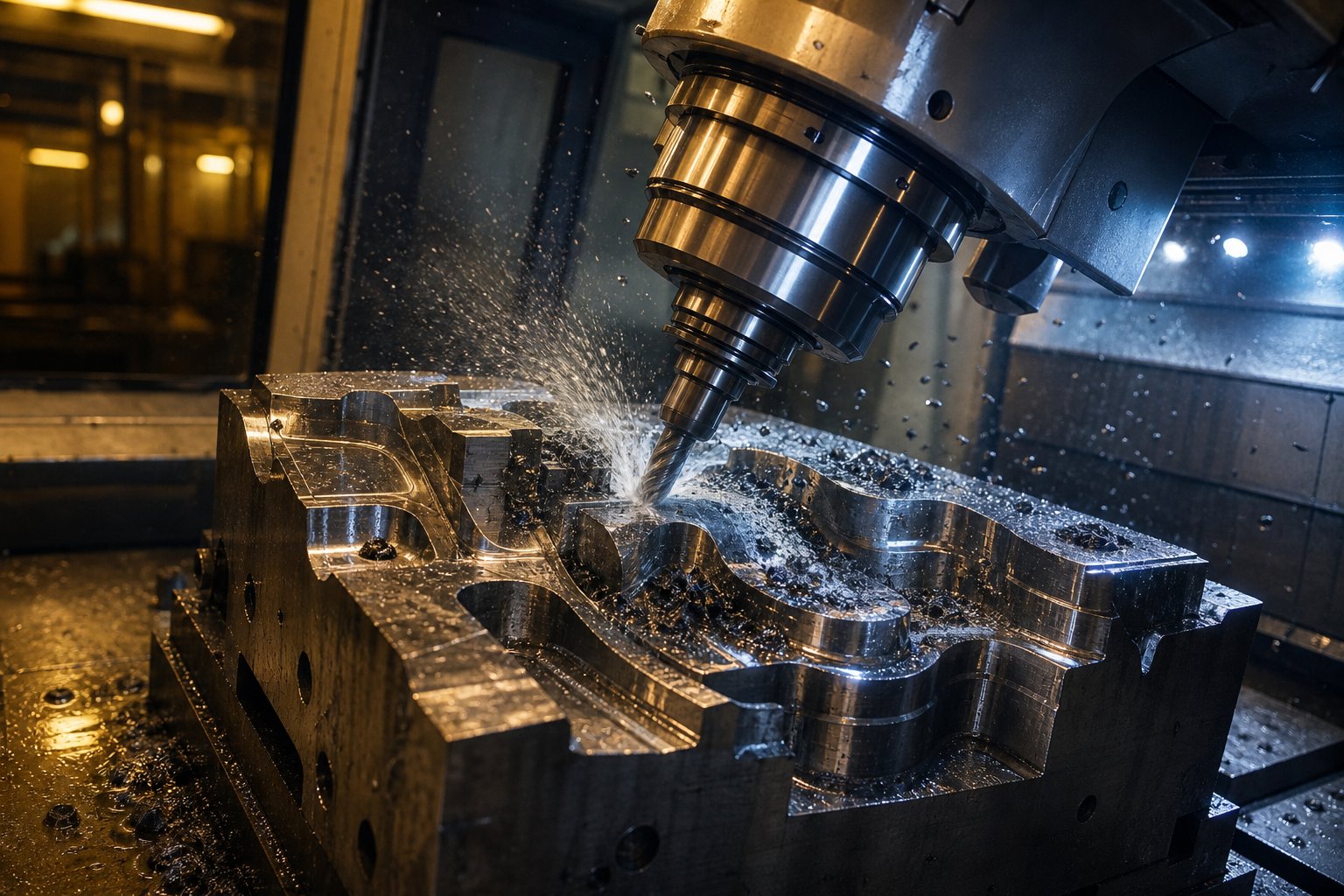
- Rough machining (CNC milling) - High-speed CNC milling machines remove the bulk of excess material, creating the general shape of each die component. Roughing typically leaves 0.5-1.0 mm of stock on all critical surfaces for later finishing. Pocket cavities, bolt holes, dowel locations, and clearance channels are all established during this phase. For complex 3D die faces, 3-axis or 5-axis machines use ball-nose cutters to rough sculpted surfaces in successive layers.
- Heat treatment - This is where the manufacturing stamping process diverges from general machining. After rough machining, die components are heat treated to achieve their target hardness. For a D2 punch block, that means austenitizing at approximately 1010 degrees C, air quenching, and double tempering to reach 58-62 HRC. Heat treatment must happen after rough machining but before finish machining because the process causes dimensional distortion, typically 0.05-0.15 mm depending on geometry and grade. Finishing operations then remove this distortion to restore precision.
- Finish machining (precision grinding and jig boring) - Hardened components are ground on surface and profile grinders to achieve flatness within 0.01 mm and surface finishes below Ra 0.4 micrometers. Jig boring machines locate precision holes (dowel pins, guide bushings) to positional tolerances of plus or minus 0.005 mm. These operations define the final functional accuracy of the die, and they can only succeed on material that has already been hardened and stress-relieved.
- Wire EDM and sinker EDM - Complex punch profiles, tight-radius internal corners, and intricate die openings are cut using wire EDM, which erodes hardened steel with a thin brass wire achieving tolerances of plus or minus 0.005 mm or better. Sinker EDM handles 3D cavity shapes, such as forming pockets or embossing details, by plunging a shaped graphite or copper electrode into the workpiece. Both processes work on fully hardened material, which is why they happen after heat treatment.
- Surface finishing and coating application - Critical die faces receive final polishing to the required surface roughness, then coatings (TiN, TiCN, TD, or others selected during the design phase) are applied. PVD coatings are deposited at temperatures below 500 degrees C to avoid softening the hardened substrate. Proper surface prep before coating, including deburring, cleaning, and sometimes pre-nitriding, directly affects coating adhesion and longevity.
- Assembly and fitting - All finished components are assembled into the die shoe. Punches are fitted to die openings with specified clearances verified using shim stock or optical measurement. Guide systems are aligned, spring forces are set, and all fasteners are torqued to specification. The assembled die undergoes a bench-level functional check: the upper and lower halves are closed by hand or with a slow-speed press to verify alignment, shut height, and interference-free operation.
- Initial tryout - The assembled die is loaded into a stamping press for its first live forming trials. Operators run the die at reduced speed, incrementally increasing press tonnage while inspecting stamped parts for dimensional accuracy, surface defects, burr height, and forming issues. Measurement against GD&T specifications identifies where adjustments are needed. Spotting (blue-dyeing and grinding contact surfaces), shimming, and clearance adjustments bring the die into specification over successive tryout iterations.
From Concept Through CAD Design
The first three stages, concept analysis, CAD modeling, and simulation, collectively determine whether the stamping process in manufacturing will succeed or struggle. Imagine committing to a 12-station progressive die build only to discover during tryout that the draw depth causes splits in your chosen material. That is an expensive lesson. Feasibility analysis and simulation exist specifically to catch these failures digitally, when changes cost hours of engineering time instead of weeks of rework on hardened steel.
Design intent also translates directly into machining requirements. A tight tolerance on a blanked hole dictates wire EDM rather than conventional punching. A polished die face for a Class A automotive surface means planning for additional grinding and lapping time. Every design decision in the CAD model carries a downstream manufacturing consequence, which is why experienced die designers think simultaneously about function and manufacturability.
CNC Machining, EDM, and Grinding Operations
The machining phases (steps 6 through 9) represent the bulk of manufacturing dies in terms of both time and cost. Rough CNC milling may consume 40-60% of the total machining hours, but it is the finish grinding, jig boring, and EDM operations that define whether the die meets its dimensional specifications.
Why does the sequence matter so rigidly? Heat treatment sits between rough and finish machining for a critical reason: cutting a fully hardened block from scratch would burn through tooling at an unsustainable rate and generate excessive heat that distorts the workpiece. Roughing the soft (annealed) material first is faster, cheaper, and more accurate. After hardening introduces its inevitable distortion, finish machining cleans up the geometry on material that is now dimensionally stable and will not move again during production use.
Wire EDM and sinker EDM occupy a unique position in the die making process. They are the only practical methods for cutting complex internal profiles in hardened tool steel without inducing mechanical stress. A progressive die with 15 piercing stations may require dozens of wire EDM setups to produce all the punch and die profiles to the required tolerances.
Heat Treatment, Assembly, and Final Fitting
Heat treatment is arguably the most underappreciated step in dies manufacturing. It transforms a machinable block of annealed steel into a wear-resistant production tool, but it also introduces the risk of cracking, warping, and dimensional change. Controlling heating rates, soak times, quench uniformity, and tempering cycles requires specialized furnace equipment and metallurgical expertise. A poorly heat-treated die component that cracks during quenching wastes all the machining time invested up to that point.
Assembly and fitting test whether every preceding stage was executed correctly. When dowel holes in the upper shoe align perfectly with those in the lower shoe, and punches enter die openings with uniform clearance on all sides, you know the cumulative accuracy from raw stock through finish machining held true. When they don't, troubleshooting begins, and it often traces back to an error introduced several stages earlier.
The initial tryout is where theory meets reality. Even with simulation and precision machining, the first parts off a new die almost always require some level of adjustment. Springback compensation may need fine-tuning, forming surfaces may need additional spotting to achieve full contact, and trim edges may need local clearance adjustments to control burr height. This iterative tryout phase is a normal and expected part of the process, not a sign of failure.
What separates a smooth tryout from a painful one is the precision embedded in every upstream stage. Simulation that accurately predicted material behavior, machining that held tolerances, and heat treatment that delivered consistent hardness all reduce the number of tryout iterations needed to reach production-ready status. That tryout and validation phase, along with the digital tools that feed into it, is where the process gets its final proof.
CAD, CAE Simulation, and CNC Integration in Die Building
The manufacturing sequence laid out in the previous section shows where simulation and CNC machining fit chronologically. But the real question is how these digital tools interact to compress lead times and prevent failures before any tool steel gets cut. In modern metal stamping die design, the 3D CAD model is not just a drawing. It is the single source of truth that drives simulation, generates machine tool paths, and ultimately defines whether the physical die replicates the digital intent.
Forming Simulation and Feasibility Analysis
Forming simulation leverages finite element analysis (FEA) to model how sheet metal behaves under the exact conditions a die will impose: binder forces, draw bead restraint, punch geometry, and material properties. The software digitally "stamps" the part and reports where problems will occur, long before a die stamping machine cycles for the first time.
What does a properly executed simulation deliver? Here are the key outputs and their practical benefit to tool & die manufacturing teams:
- Thinning maps - Identify regions where material stretches beyond safe limits, predicting splits before they happen on the press floor.
- Springback compensation - Calculate how much the die faces must be over-bent or morphed to achieve the target part geometry after elastic recovery.
- Wrinkling prediction - Highlight areas of excessive compression that will cause buckles or surface waves, guiding binder pressure and draw bead adjustments.
- Draw-bead optimization - Determine the ideal restraint force and bead geometry to control material flow without causing splits or excess thinning.
- Blank shape optimization - Define the minimum flat blank contour needed to form the part completely, directly reducing material waste and per-part cost.
- Press force prediction - Calculate the minimum tonnage required to fully form the part, enabling production planners to assign the right press line with confidence.
The critical insight from real-world case studies is that simulation accuracy depends on replication fidelity. A passing simulation only predicts success at the press if the physical die is built to the exact conditions modeled: actual tested material properties, actual lubrication values, actual draw bead geometry. When die builders deviate from simulation parameters during construction, the digital prediction loses its validity. As one veteran die engineer documented across four forensics investigations in automotive, appliance, and IT sectors, simulations that passed during feasibility still produced failures at the press because the physical dies did not replicate the simulation's digital DNA.
This means the simulation phase is not a one-and-done checkpoint. It is iterative. Design teams cycle between CAD geometry changes and simulation runs, sometimes hundreds of iterations, until a robust passing result is achieved with tested material data. Only then should the design freeze and die build begin.
5-Axis CNC and High-Speed Machining for Die Components
Once simulation validates the die face geometry, that same 3D CAD model feeds directly into CAM software to generate CNC tool paths. For complex sculpted surfaces found on draw dies and form steels, 5-axis high-speed machining has become essential metal stamping tooling technology.
Why does 5-axis matter for die faces? A draw die for an automotive body panel features continuously curved surfaces that change direction in three dimensions. On a 3-axis machine, a ball-nose end mill approaches these surfaces straight down, which means the tool tip (where cutting speed approaches zero) does the work at steep transitions. The result is poor surface finish, extended cycle times from ultra-fine step-overs, and hours of hand polishing afterward.
With simultaneous 5-axis machining, the spindle tilts to maintain an optimal cutting angle relative to the surface throughout the entire pass. The effective cutting edge, not the tool tip, stays engaged. This delivers better surface finish in less time, often eliminating manual bench work entirely on complex die faces. For an industrial metal stamping machine die set with deep cavities and undercut features, 5-axis also allows shorter, stiffer tools that reduce chatter and improve dimensional accuracy.
Wire EDM programming follows the same digital thread. Complex punch profiles and die openings are extracted directly from the CAD model and converted into wire path code, ensuring the physical machine die geometry matches the simulated die geometry exactly. This closed-loop connection between design and manufacturing is what makes congruence between simulation and press results achievable.
How Digital Tools Reduce Lead Time and Risk
The combined effect of simulation and CNC integration on the automation tool & die workflow is measurable. Projects that once required three to five physical tryout iterations to reach production approval now regularly achieve first-hit-pass outcomes when the digital chain remains unbroken from simulation through machining.
Consider the practical impact: each avoided tryout iteration saves one to three weeks of spotting, adjustment, re-machining, and re-testing. On a complex progressive die, eliminating even two tryout loops can compress the overall project timeline by four to six weeks and cut development costs significantly. High-speed 5-axis machining further compresses lead time by finishing complex die faces in a single setup rather than multiple 3-axis operations with manual repositioning between them.
The digital toolchain also de-risks the build. When forming simulation predicts that a specific geometry is robust against normal material property variation, and CNC machining replicates that geometry within microns, the probability of a catastrophic failure at tryout drops dramatically. The stamping industry today has the most accurate simulation software, the most precise machining capability, and the highest-performing presses in its history. The challenge is maintaining discipline across the full chain so that digital predictions translate into physical results.
That translation gets its ultimate test during tryout and validation, where measurement data confirms whether the digital-to-physical handoff held true across every stage of the build.
Die Tryout, Validation, and Production Approval
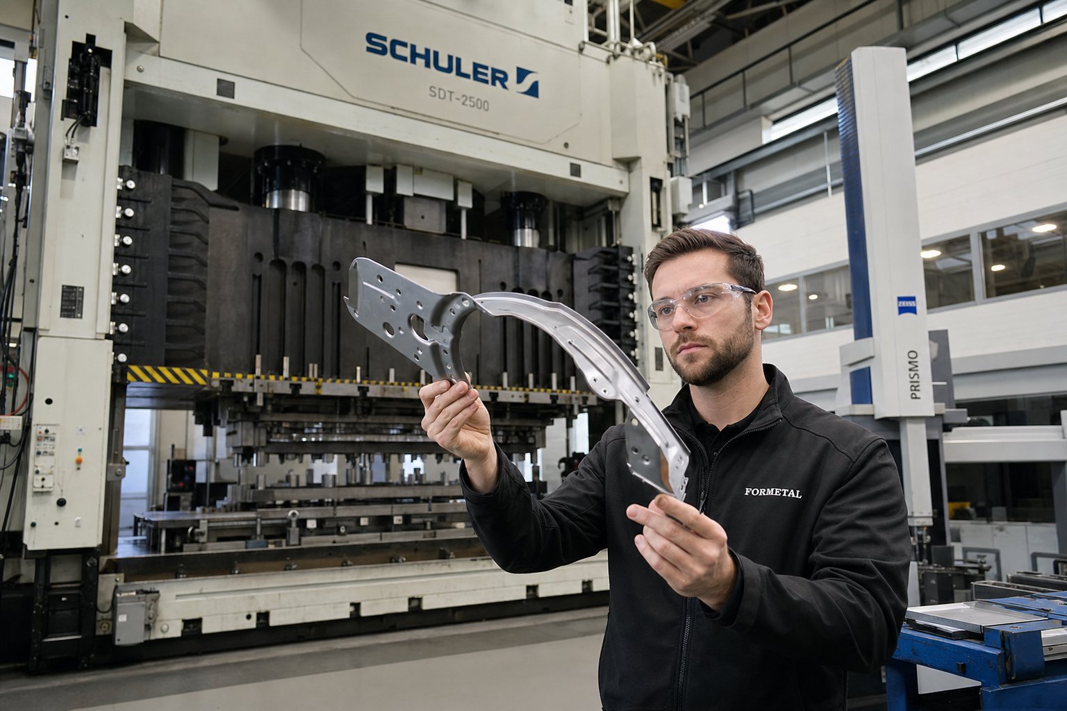
Simulation predicted success. CNC machining replicated the geometry within microns. The die is assembled, coated, and sitting on the press bed. Does it actually produce good parts? Tryout is where the entire upstream process earns its credibility or exposes its weaknesses. For precision die and stamping operations, this phase is not optional polish. It is the systematic proof that a custom metal stamp die will deliver conforming parts under real production conditions.
Die Tryout Process and Iterative Adjustment
The initial tryout follows a deliberate, incremental protocol rather than running the die at full speed from the first hit. Here is how it typically unfolds:
- Press setup and alignment - The die is loaded into the designated tryout press (matched to tonnage requirements from simulation), shimmed to achieve correct shut height, and aligned with bolster T-slots. Feed lines, pilot positions, and scrap chutes are all verified before the first stroke.
- Slow-speed forming trials - Initial hits run at reduced speed, often single-stroke mode, with press tonnage brought up incrementally. Engineers inspect each die stamped part for visible issues: splits, wrinkles, off-center blanks, or uneven draw depth.
- Measurement against GD&T specifications - Once parts appear visually acceptable, critical dimensions are checked against the print. Hole locations, profile tolerances, flatness callouts, and trim line positions all get measured. Deviations are logged and mapped back to specific die stations or forming surfaces.
- Spotting and adjustment - Where forming surfaces show uneven contact (checked with bluing compound), die makers spot-grind high points until full-face contact is achieved. Clearances are shimmed, timing adjusted, and draw beads modified based on measured results. Each adjustment cycle produces another set of sample parts for re-measurement.
This iterative loop, form parts, measure, adjust, re-form, continues until all dimensions fall within specification. A straightforward draw die might reach approval in two or three iterations. A complex progressive die with 12 or more stations and tight GD&T callouts could require five to eight cycles over several weeks. The precision die stamping industry accepts this iteration as normal engineering practice, not rework.
A thorough tryout process costs hours on the front end but eliminates months of production interruptions, scrap, and customer rejects on the back end. The investment in getting it right before signing off always costs less than chasing quality problems at full production speed.
Inspection Methods and Quality Verification
Measuring die stamped parts from tryout requires more than a caliper and a trained eye. The quality control toolkit for precision die & stamping validation includes multiple technologies, each serving a specific purpose:
- Coordinate Measuring Machines (CMM) - Touch-probe systems measure complex 3D geometries against CAD nominal data, verifying profile tolerances, true position of hole patterns, and angular relationships. CMM inspection is the gold standard for metal stamping die sets producing parts with positional tolerances below plus or minus 0.1 mm.
- Optical and laser scanning - Non-contact 3D scanners capture full-surface geometry and generate color deviation maps showing exactly where a part deviates from nominal. This is especially valuable for detecting subtle springback or twist that point measurements might miss.
- Material thickness measurement - Ultrasonic thickness gauges or sectioned samples verify that forming operations have not thinned the material beyond allowable limits specified in the design. Excessive thinning signals a forming issue that will cause field failures even if external dimensions look correct.
- Statistical Process Control (SPC) - During extended trial runs (typically 300 or more consecutive parts), critical dimensions are sampled at regular intervals and plotted on control charts. SPC data reveals whether the process is stable and capable, not just whether individual parts pass inspection.
For custom precision stamping applications serving automotive or medical markets, the inspection plan is defined before tryout begins. It specifies which features get measured, at what frequency, using which equipment, and what acceptance criteria apply. This planning ensures that tryout data directly feeds into the production approval documentation.
Moving From Trial Runs to Production Approval
Producing a handful of good parts is not the same as proving production capability. Formal production approval, most commonly structured as a Production Part Approval Process (PPAP) in automotive supply chains, requires demonstrating that the process can produce conforming parts consistently and repeatably under normal production conditions.
A standard PPAP submission typically includes process flow diagrams, control plans, measurement system analysis, dimensional results from a production trial run, material certifications, and capability studies showing CpK values above 1.33 for critical characteristics. The Part Submission Warrant (PSW) formally confirms that the supplier has met all requirements and the process is ready for series production.
The timeline from initial concept through final production sign-off varies by die complexity:
| Project Phase | Simple Die | Progressive Die | Transfer Die |
|---|---|---|---|
| Feasibility and design | 2-3 weeks | 4-6 weeks | 6-8 weeks |
| Die build (machining through assembly) | 3-4 weeks | 8-12 weeks | 10-14 weeks |
| Tryout and validation | 1-2 weeks | 3-6 weeks | 4-8 weeks |
| Production approval (PPAP or equivalent) | 1-2 weeks | 2-4 weeks | 2-4 weeks |
| Total concept to sign-off | 7-11 weeks | 17-28 weeks | 22-34 weeks |
Full-service die manufacturers like YICHEN integrate trial runs and dimensional inspection into their standard workflow, handling feasibility analysis through machining, tryout, and final production approval under one roof. For engineers evaluating potential partners, this in-house coverage from concept through sign-off eliminates the coordination overhead of splitting work across multiple vendors and keeps accountability clear when issues arise during validation.
Production approval marks the transition from tooling development to ongoing manufacturing. But the economics of that manufacturing, specifically the per-part cost at scale, were already determined much earlier in the process by a decision that many engineers underestimate: how the strip was laid out inside the die.
Strip Layout Optimization and Die Design Economics
Per-part cost in any sheet metal stamping process is dominated by one variable that gets locked in before the die is even built: material utilization. The strip layout, meaning how parts are oriented and spaced on the coil, determines what percentage of purchased steel becomes product versus scrap. When you stamp sheet metal at volumes of 500,000 or 5 million parts, even a small improvement in utilization compounds into significant savings. And conversely, a layout designed without rigor can silently inflate your per-part cost for the life of the program.
Strip Layout Fundamentals and Material Utilization
A strip layout is the engineered blueprint that defines the progression of operations inside a progressive or transfer die. It specifies how each part nests within the coil width, where pilot holes locate, how the carrier web connects stations, and where scrap is shed. The industry benchmark for a well-designed layout targets at least 75% material utilization, meaning 75% of the purchased steel ends up in finished parts rather than the scrap bin.
Three geometric parameters control utilization directly:
- Scrap bridge width - The thin web of material left between adjacent parts and between parts and the strip edge. A common rule of thumb sets bridge thickness at 1.25 to 1.5 times the material thickness. Too narrow, and the scrap twists or jams the die. Too wide, and you waste material on every single hit.
- Progression pitch - The distance the strip advances with each press stroke. Pitch equals part length plus one bridge width. Tighter pitch means more parts per meter of coil, but only if the die stations can physically fit within that spacing.
- Part orientation and nesting - Irregularly shaped parts can often be rotated, tilted at an angle, or arranged in alternating orientations to interlock like puzzle pieces. This angular nesting can recover 10-15% more material compared to a simple straight single-row layout, though it typically increases die complexity.
The purpose of bypass notches in stamping dies connects directly to layout efficiency. These notches, cut into the carrier strip, allow material to flow during forming operations without distorting adjacent stations or the progression pitch. Without properly placed bypass notches, deep draws or bends would pull material from neighboring features, destroying accuracy across the entire strip. They are a layout design tool, not just a structural convenience.
How Layout Decisions Affect Tooling Cost
Here is the tension most engineers feel when designing a sheet metal die layout: aggressive nesting saves material per part but forces the die to grow in complexity. More stations, tighter clearances, and more intricate scrap-shedding paths all increase die build cost. The question becomes whether the per-part material savings over the expected production volume outweigh the higher upfront tooling investment.
Consider how material utilization percentage impacts the economics of a steel sheet stamping program across different production volumes:
| Material Utilization | Scrap Percentage | Relative Material Cost per Part | Impact at 100K Parts | Impact at 1M Parts | Impact at 5M Parts |
|---|---|---|---|---|---|
| 65% | 35% | Baseline (1.00x) | Baseline | Baseline | Baseline |
| 75% | 25% | 0.87x | Moderate savings | Significant savings | Major cost reduction |
| 80% | 20% | 0.81x | Moderate savings | Large savings | Substantial cost reduction |
| 85% | 15% | 0.76x | Good savings | Very large savings | Program-defining cost advantage |
Since material typically accounts for 40% to 60% of total stamped part cost, moving from 65% to 80% utilization reduces your per-piece material spend by roughly 19%. Over a million-part run in a metal pressing process, that difference translates directly to bottom-line margin or competitive pricing advantage.
Layout decisions also cascade into die size and station count. A more compact pitch shortens the overall strip length per part, which reduces die length and potentially eliminates one or two stations. Smaller dies mean smaller press beds, lower tooling weight, and faster changeover. On the other hand, aggressive material savings sometimes require adding idle stations for structural support, adding scrap-cutting stations to break large offal into manageable pieces, or widening the die to accommodate angular nesting. Each of these additions increases die cost.
Balancing Material Savings Against Die Complexity
Experienced die designers approach layout optimization as a whole-system calculation, not a single-metric exercise. Saving an extra 3% on material utilization by switching from a single-row layout to an angular nested arrangement might add 15-20% to die build cost due to increased station count and unbalanced cutting forces. Whether that tradeoff pays off depends entirely on production volume and program duration.
A few practical guidelines help frame the decision:
- For production runs under 100,000 parts, simple single-row layouts usually win because die cost dominates total economics. The material penalty is real but small in absolute terms.
- For runs between 100,000 and 1 million, optimization efforts on bridge width, pitch, and coil width selection deliver meaningful returns without radical die redesign.
- For runs above 1 million parts, every percentage point of utilization matters. Investing in angular nesting, common-edge designs, or multi-row layouts pays for itself many times over through accumulated material savings.
Carrier strip design also factors into this balance. A solid carrier offers maximum stability and simpler die construction for flat parts, but it consumes strip width that could otherwise hold product. A stretch web carrier uses strategically placed cuts to allow material flow during forming, accommodating parts with draw depth or vertical movement between stations. The carrier choice affects both utilization and die robustness, and getting it wrong means either strip buckling during feed or material starvation during forming.
The layout is ultimately a commitment. Once the metal press dies are built around a specific strip layout, changing it means rebuilding or heavily modifying the tooling. Engineers who invest time in layout optimization up front, leveraging simulation and nesting software to compare multiple scenarios, protect their programs against years of avoidable material cost. That upfront effort locks in economics. Sustaining those economics across the full production life of the die, however, requires a disciplined approach to maintenance and lifecycle management.
Die Maintenance and Lifecycle Management
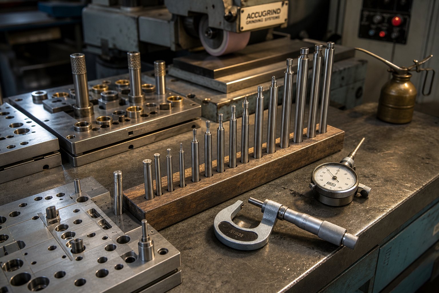
Strip layout locks in material economics. But those savings erode quickly if the die degrades faster than planned. A stamping die that ran clean at hit 100,000 can start producing burrs, dimensional drift, or surface marks by hit 200,000 if nobody tracked the wear and acted before it compounded. Effective stamping die maintenance is what separates a tool that delivers its full rated life from one that drains budget through unplanned downtime and scrap.
Scheduled preventive maintenance extends stamping die service life by 2-3x compared to run-to-failure approaches. The cost of planned downtime is always lower than the cost of emergency repairs, rejected parts, and missed shipments.
Preventive Maintenance Schedules and Wear Indicators
A strong stamping tool and die maintenance program combines calendar-based checks with stroke-count triggers. Time alone does not capture how hard a die works. A tool running 200 strokes per minute on abrasive stainless steel wears far faster than one cycling at 40 SPM on mild steel. Industry best practice ties sharpening reviews and component inspections to actual hit counts rather than arbitrary dates.
Here is a practical maintenance checklist that metal stamping tool and die technicians can apply immediately:
- Every shift - Check for burrs on stamped parts, clear visible slugs and debris, confirm lubricant delivery, and listen for abnormal press noise.
- Daily - Inspect pilots, springs, and strip guides. Clean scrap paths and verify feed pitch accuracy.
- Weekly - Measure wear on cutting edges and forming surfaces. Torque-check critical fasteners. Log hit count and any quality deviations.
- Monthly - Deep clean all stations. Inspect guide pins and bushings for scoring. Review sharpening history against wear trends and plan regrinding during controlled downtime.
- At stroke-count intervals (typically 10,000-50,000 hits depending on material) - Perform full bench teardown, inspect all stamping die parts for wear or damage, measure punch-to-die clearances, and replace springs that have lost more than 10% of free length.
Common wear indicators that signal service is overdue include burr height exceeding material thickness on cut edges, visible edge rounding or chipping on punches, scoring on guide elements, uneven witness marks on forming surfaces, and recurring misfeeds that trace back to pilot wear or strip control degradation.
Regrinding Procedures and Sharpening Best Practices
Punch and die regrinding is the most frequent stamping tool repair action in any toolroom. The general guideline calls for resharpening every 10,000 to 15,000 hits, or sooner if burrs become visible. Delaying regrinding beyond the point of initial dulling accelerates wear exponentially because a rounded edge requires higher cutting forces, which increase heat and plastic deformation at the cutting zone.
A few rules keep regrinding effective:
- Remove only the minimum material needed to restore a clean, sharp edge, typically 0.05-0.1 mm per grind.
- Use fine-grain grinding wheels to prevent overheating, which can draw temper from the hardened tool steel and create a soft zone that wears immediately.
- Maintain the original grind angle. For mild steel work, punch faces stay flat (0 degrees). Harder materials may use a 2-4 degree shear angle to reduce peak cutting force.
- After regrinding, adjust shut height or add shims to compensate for material removed. A punch that is 0.2 mm shorter than design changes the timing relationship with its mating die opening.
- Track cumulative grind depth per component. Most punches allow 3-5 mm of total regrinding before they must be replaced.
Keeping spare stamping die parts on hand for high-wear items, particularly punches, pilots, springs, and bushings, prevents a single worn component from idling an entire press line while the toolroom fabricates a replacement.
Die Lifecycle Economics and Replacement Decisions
Every tool and die stamping operation eventually faces the same question: sharpen again, refurbish the whole die, or build new? The answer lives in the maintenance records.
Sharpening makes sense when edge wear is the primary issue and the die remains dimensionally stable after service. Refurbishment, meaning reconditioning multiple components, restoring clearances, and resurfacing forming areas, is justified when cumulative wear has degraded overall die accuracy but the basic structure remains sound. Replacement becomes the better path when you see repeated alignment loss after verified maintenance, chronic dimensional drift that shimming cannot correct, structural cracking, or when the part design has changed enough that retrofitting the existing die costs more than starting fresh.
A practical decision threshold: if regrinding frequency has doubled over the last quarter while die output quality continues to deteriorate, the tool has likely passed its economic service life. At that point, continued maintenance spending generates diminishing returns compared to investing in a new die built with current simulation data and optimized strip layout.
Tracking hit counts, defect trends, and maintenance costs per die over time transforms this decision from intuition into data. The shops that maintain detailed lifecycle records know exactly when a tool crosses from productive asset to cost burden, and they plan replacements proactively rather than reacting to production crises. That same data-driven discipline also applies when evaluating external die manufacturers, where the question shifts from maintaining existing tooling to selecting the right partner for new builds.
How to Select the Right Stamping Die Manufacturer
Knowing how a die should be built, validated, and maintained gives you a sharp lens for evaluating the people who actually do the work. The gap between die manufacturing companies that execute the full process under one roof and those that farm out critical steps to subcontractors often shows up as missed timelines, finger-pointing during tryout, and parts that never quite hit specification. Choosing a metal stamping die manufacturer is ultimately a risk management decision disguised as a procurement task.
Critical Capabilities to Verify Before Sending an RFQ
Before you send drawings to a list of stamping die manufacturers, establish a baseline of what "full-service" actually means. Not every shop that calls itself a die manufacturer handles every phase internally. Use this checklist to qualify candidates:
- In-house CAD/CAE design and forming simulation - Can they run feasibility analysis, springback compensation, and thinning studies without outsourcing? This capability directly affects iteration speed when problems surface.
- CNC machining capacity - Look for 3-axis and 5-axis high-speed mills, wire EDM, sinker EDM, and precision surface grinders. Ask about maximum workpiece size and current machine utilization rates.
- Heat treatment control - Whether done in-house or through a certified partner, the manufacturer should control heat treatment specifications and verify results with hardness testing on every component.
- Tryout press availability - A dedicated tryout press (matched to production tonnage) lets the builder validate the die under realistic conditions without depending on your schedule or a third-party facility.
- Inspection and metrology equipment - CMM, optical scanning, SPC capability, and documented inspection plans indicate a shop that proves its work rather than shipping and hoping.
- Material expertise - Confirm experience with your specific workpiece material, especially if you are running AHSS, stainless, or aluminum. Custom metal stamping dies for demanding materials require different tool steels, coatings, and clearance strategies than mild steel work.
- Certifications - ISO 9001 at minimum. IATF 16949 if you serve automotive. These are not just badges; they indicate documented processes, traceability, and corrective action systems.
Evaluating a Manufacturer's Design-to-Production Workflow
An RFQ response tells you more than just price. Pay attention to how metal stamping die manufacturers describe their process. A strong response includes a phase-by-phase timeline with clear milestones, identifies potential forming challenges in your part geometry, proposes specific die configurations with rationale, and names the simulation software and CNC equipment they will use. Vague promises like "we can handle it" without technical specifics are a red flag.
Ask pointed questions during qualification: How many tryout iterations does your average custom metal stamping die require before sign-off? What is your first-time-pass rate on PPAP submissions? Can you share a sample project timeline for a die of similar complexity? Manufacturers with disciplined internal tracking answer these questions with data. Those without it guess.
Communication practices also separate strong partners from problematic ones. Look for dedicated project managers, regular progress reports with photos or videos of machining and assembly milestones, and willingness to involve your engineering team during simulation reviews. A stamping dies manufacturer that treats the build as a black box until delivery day leaves you exposed to surprises that cost weeks to resolve.
Moving From Research to RFQ-Ready Decisions
If you have followed this guide through material selection, manufacturing sequences, simulation integration, and tryout methodology, you now have the vocabulary and evaluation framework to hold any die manufacturer accountable to real process standards. The goal is finding a partner whose internal workflow mirrors the complete sequence covered in this article: feasibility, simulation, precision machining, controlled tryout, and documented production approval.
YICHEN is one example of a full-service partner that covers this entire chain, from CAE simulation and 5-axis CNC machining through trial runs and dimensional inspection, under a single project management structure. For sourcing managers and tooling engineers ready to move past research and into active quoting, their custom stamping die capabilities provide a concrete reference point for what an integrated design-to-approval workflow looks like in practice.
Regardless of which die manufacturing companies make your short list, the principles remain the same: verify capabilities with evidence, demand transparency through milestones, and choose a partner whose process discipline matches the complexity of your parts. The tooling you source today will run for years. The manufacturer behind it should earn that commitment before the first block of tool steel is cut.
Stamping Dies Manufacturing FAQs
1. What are the main types of stamping dies and how do I choose between them?
The five main types are simple dies, compound dies, combination dies, progressive dies, and transfer dies. Selection depends on production volume, part complexity, and budget. Simple dies suit prototypes and low volumes under 10,000 parts. Compound and combination dies handle moderate volumes with multiple operations in a single stroke. Progressive dies are ideal for high-volume runs exceeding 100,000 parts annually, feeding coil through sequential stations automatically. Transfer dies serve large or geometrically complex parts that cannot remain on a carrier strip. Matching die type to your specific production parameters avoids overpaying for unnecessary capability or bottlenecking output.
2. What tool steel is best for stamping dies?
The best tool steel depends on your workpiece material and production volume. D2 (high-carbon, high-chromium) is the standard for blanking and trimming mild steel at 58-62 HRC. S7 offers superior shock resistance for bending operations. DC53 provides double the toughness of D2, making it suitable for piercing advanced high-strength steels. For materials above 590 MPa, powder metallurgy tool steels deliver up to 10x the impact strength of conventional grades. Carbide inserts are justified at multi-million part volumes or when stamping abrasive materials like stainless steel or silicon steel laminations where dimensional stability must hold without frequent resharpening.
3. How long does it take to manufacture a stamping die from concept to production approval?
Total lead time ranges from 7 to 34 weeks depending on die complexity. A simple single-station die typically takes 7-11 weeks covering design, machining, tryout, and PPAP approval. Progressive dies require 17-28 weeks due to multi-station complexity, extended machining time, and iterative tryout cycles. Transfer dies for large structural parts need 22-34 weeks. The tryout and validation phase alone can consume 3-8 weeks for complex tooling, as each iteration involves forming parts, measuring against GD&T specifications, adjusting die surfaces, and re-running trials until all dimensions fall within tolerance consistently.
4. How does forming simulation reduce stamping die development risk?
Forming simulation uses finite element analysis to digitally stamp parts before any tool steel is cut, predicting splits, wrinkles, thinning, and springback. This allows engineers to iterate on die face geometry, draw bead design, and blank shape in software rather than on physical tooling. Projects using validated simulation regularly achieve first-hit-pass outcomes at tryout, potentially eliminating 2-3 physical iterations that would each cost 1-3 weeks. The critical requirement is that the physical die must replicate simulation conditions exactly, including actual material properties, lubrication values, and bead geometry, for predictions to hold true at the press.
5. How often should stamping dies be sharpened and maintained?
Punch and die regrinding is generally recommended every 10,000-15,000 hits, or sooner if burrs become visible on stamped parts. Maintenance intervals should be tied to actual stroke counts rather than calendar dates, since wear rate depends heavily on workpiece material hardness and press speed. Each regrind should remove only 0.05-0.1 mm of material to restore a clean edge. Most punches allow 3-5 mm of total cumulative regrinding before replacement is needed. Beyond edge sharpening, full bench teardowns at manufacturer-specified hit count intervals should inspect all components including springs, pilots, guide bushings, and forming surfaces for wear patterns that indicate broader service needs.


