


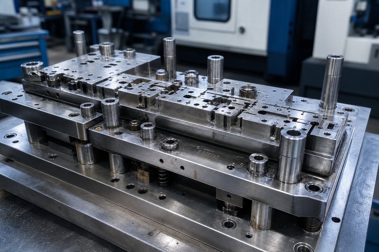
What Making a Metal Stamping Die Really Means
When you search for information on making metal stamping dies, you typically land on one of two extremes: a hobbyist punching holes in thin sheet metal or a dense textbook chapter filled with equations. This article fills the gap between those worlds, walking you through what professional die construction actually looks like from raw steel to the first production hit.
What Is a Stamping Die and What Does Making One Involve
So what is dies in manufacturing? At its core, a stamping die is a precision tool composed of two mating halves that cut, bend, or form sheet metal into a finished shape under press force. The upper and lower halves house punches, die cavities, strippers, pilots, and guide components that work together to locate material, perform operations, and release the finished part. A simple stamping definition: a high-force process that transforms flat sheet into three-dimensional components at production speed.
But here is the distinction most content overlooks. Operating a stamping die means loading it into a press and running parts. Making one means engineering every component from a block of tool steel, machining it to micron-level tolerances, hardening it, and proving it produces acceptable parts before it ever reaches production. What is a stamping press without a properly built die? Just tonnage with nowhere useful to go.
The scope of this article focuses entirely on the construction side: design, machining, heat treatment, inspection, and validation. If you are asking what are dies and how they get built, you are in the right place.
Why Die-Making Precision Determines Part Quality
Every dimension on a stamped part traces directly back to how its stamping dies were manufactured. Punch-to-die clearance controls burr height. Cavity geometry dictates material flow. Surface finish on forming steels determines whether parts release cleanly or gall and stick. When tolerances drift by even a few thousandths of an inch, scrap rates climb, press downtime increases, and cost per hit rises.
The die is the DNA of every stamped part. Every surface finish defect, dimensional error, or burr traces back to how the die was made.
Understanding what is metal stamping at a practical level means recognizing that metal stamping dies are not generic tools. They are custom-built instruments where each design choice, material selection, and machining operation compounds into the quality, longevity, and economics of every part they produce. The sections ahead break down exactly how that happens, starting with the digital engineering phase that precedes any chip cutting.
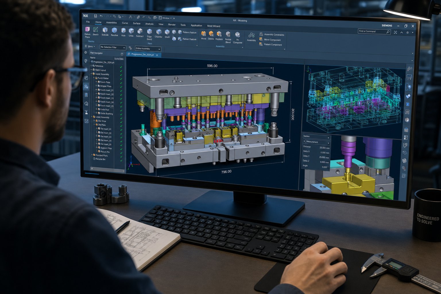
Die Design Workflow from CAD Modeling to CAM Programming
Before any tool steel is cut, a stamping die exists entirely as digital geometry. The front-end engineering phase is where cost, accuracy, and production performance are largely determined, yet it is the step most discussions of die construction skip over. Modern stamping die design relies on three interconnected digital disciplines: 3D CAD modeling to define every component, CAE simulation to validate forming behavior, and CAM programming to generate the toolpaths that will machine each part. Get this phase right and you reduce tryout loops, scrap, and rework. Get it wrong and you pay for those mistakes in steel.
3D CAD Modeling for Punch and Die Geometry
Metal stamping die design starts with a 3D parametric model of the finished stamped part. Engineers import the part geometry, typically as a STEP or native CAD file, and begin working backward from the final shape to define how the die must form it. This reverse-engineering approach is where sheet metal stamping design diverges from general mechanical design. You are not just modeling solid components; you are modeling the negative space and motion that will produce a part millions of times.
Parametric modeling means every dimension is driven by relationships. Change a punch radius and the mating die cavity, stripper opening, and backing plate pocket all update automatically. This associativity prevents the mismatches that cause interference during assembly. Punches get modeled with their cutting profiles, land lengths, and shear angles. Die blocks receive cavity geometry with proper clearances for the specific material and thickness being stamped. Strippers, pilots, guide pins, and heel blocks all take shape within the same assembly model, ensuring that every component works as a coordinated system.
Strip layout is a critical part of this modeling phase. The designer determines how the flat strip will nest, how much material sits between parts, where carrier tabs connect, and what pitch distance separates stations. A well-planned strip layout balances material utilization against forming force distribution and feed stability. Poor nesting wastes material. Poor sequencing creates unbalanced forces that wear the die unevenly.
CAE Simulation to Predict Forming Behavior
Imagine pressing a complex shape from high-strength steel and discovering that the draw wall thins to the point of cracking, but only after you have already machined the die cavities. That scenario used to be common. Today, CAE simulation predicts these failures before any physical tool exists, making it one of the most valuable metal stamping techniques available to die engineers.
Finite element analysis models the entire forming process: blank holder contact, punch travel, material flow into cavities, and the elastic recovery that follows. Simulation identifies wrinkling in unsupported areas, thinning in tight radii, and cracking where strain exceeds material limits. It also predicts springback, which is the tendency of formed metal to partially recover its shape once press force is removed. For high-strength steels, springback can be severe enough to push parts out of tolerance entirely. Advanced simulation tools now calculate springback magnitude across the entire part surface, allowing engineers to compensate die geometry proactively rather than chasing corrections during tryout.
This compensation works by intentionally modifying the die face so the part springs back into its correct final shape. Without simulation, engineers relied on physical trial-and-error, overbending by guesswork and iterating through expensive die recuts. Stamping technology has advanced to the point where a metal stamping prototype can be validated digitally before committing to hard tooling, cutting weeks from development timelines and eliminating entire rounds of physical sampling.
CAM Programming and Toolpath Strategy
With geometry locked and simulation validated, CAM programming translates the design into machine instructions. Every contour, pocket, and profile on every die component needs a toolpath that balances surface finish, dimensional accuracy, and cycle time. This is where stamping design decisions meet manufacturing reality.
CAM programmers define roughing strategies that remove bulk material quickly, leaving stock for semi-finish and finish passes. They select cutter geometries matched to specific features: ball-nose end mills for contoured cavities, flat end mills for planar surfaces, and small-diameter tools for tight corners. Toolpath strategies like high-speed machining with constant chip load reduce cutting forces and extend tool life, which matters when you are machining hardened tool steel at 60+ HRC after heat treatment.
For complex die profiles with compound curves and undercuts, 5-axis simultaneous programming keeps the cutter oriented optimally to the surface, reducing scallop height and minimizing hand polishing. Simpler planar geometries may only need 3-axis work. The programmer makes these decisions component by component based on geometry complexity and tolerance requirements.
The typical metal stamping design workflow from concept to machine-ready programs follows a defined sequence:
- Part geometry import and feasibility review
- Strip layout, nesting, and operation sequencing
- Die component modeling with full parametric associativity
- Forming simulation, springback prediction, and die face compensation
- Toolpath generation, simulation verification, and post-processing for CNC
Each step feeds the next. Skipping simulation to save time almost always costs more in rework. Rushing CAM programming leads to poor surface finishes that require excessive hand work. The digital phase is where discipline pays dividends, because once you start cutting steel, changes become exponentially more expensive. That transition from digital model to physical metal, the actual machining of die components, is where construction complexity reveals itself most clearly.
Types of Stamping Dies and How Construction Differs
Not all stamping dies are built the same way, and construction complexity varies dramatically depending on the type. A single-station blanking die might require a few weeks of machining. A 20-station progressive die for an automotive stamping die application can take months of precision work across dozens of interrelated components. Understanding the types of stamping dies helps explain why build strategies, tolerances, and costs differ so widely across projects.
Single-Station Dies vs Compound Dies
Single-station dies represent the simplest category of sheet metal stamping dies. Each press stroke performs one operation: a blank, a pierce, or a single form. Construction is relatively straightforward because you are building one set of mating tools with one alignment concern. Simple dies handle basic jobs like cutting washers or piercing mounting holes in brackets.
Compound dies raise complexity a notch. They perform multiple cutting operations in a single stroke at a single station. A typical compound die might blank an outer profile and pierce internal holes simultaneously. The construction challenge here is concentricity. Every punch and die opening must align precisely because they all engage the material at the same instant. Tolerances tighten, and the die maker must account for deflection under simultaneous cutting forces.
Combination dies go a step further by mixing cutting and forming in one stroke. You might blank a shape and draw it into a cup in a single press cycle. Building these requires the die maker to manage both shearing clearances and forming radii within the same tool, which demands careful attention to how material flows during the combined operation. Still, all of these are single-station tools. The real escalation in build complexity happens when you move to stage tooling that processes a strip through multiple stations.
Progressive Die Construction and Station Sequencing
Progressive dies are the workhorse of high-volume stamping. They perform a series of operations across multiple stations with each press stroke, gradually transforming a metal strip into a finished part. As MetalForming Magazine describes it, a progressive die performs fundamental sheet metal operations in two or more stations simultaneously, with the strip moving a predetermined distance during each stroke through an automated feed system.
Sounds straightforward in principle. In practice, building one is among the most demanding tasks in tool and die manufacturing. Here is why:
- Station-to-station alignment: Every station must hold position relative to all others within microns. A cumulative shift of even 0.01 mm across ten stations produces parts out of tolerance. The die maker machines all station features from common datums and verifies alignment across the entire die set.
- Pitch control: Pitch is the fixed distance the strip advances between strokes. Every feature in every station must be spaced at exact pitch multiples. If a piercing punch in station three sits 0.02 mm off pitch from the form tooling in station eight, those features will not align on the finished part.
- Strip guidance and lifting: The strip must feed smoothly through all stations without catching on formed features or sagging between lifters. Bar lifters, stock guides, and relief pockets between stations all require precise machining to maintain a level feed plane.
- Inter-station timing: Pilots enter previously pierced holes to register strip position before each operation engages. These pilots must enter and retract in coordination with strippers and lifters. Timing errors cause strip damage or missed registrations.
The use of negative and positive bypass notches in sheet metal stamping dies also plays a role in progressive die construction. These notches on the strip edge provide physical reference points for pitch location and allow sensors to detect short or long feeds before they cause damage. Building the notching station with the correct geometry and position is one of the first alignment-critical operations in the die.
Construction of steel stamping dies for progressive applications also demands exceptional consistency in component manufacturing. Every punch, die insert, and backing plate must be ground flat and parallel. Guide pins and bushings must hold the upper and lower shoes in alignment under dynamic press loads. A progressive die is not just a collection of stations; it is a coordinated mechanical system where each component influences the performance of every other.
Transfer Dies for Large or Deep-Drawn Parts
Transfer stamping takes a different approach. Instead of keeping parts attached to a carrier strip, individual blanks are cut free at the first station and mechanically transferred between subsequent stations by grippers or shuttle mechanisms. This method suits large parts, deep-drawn shells, and geometries that cannot remain connected to a strip during forming.
Building transfer dies introduces its own complexity. Each station functions as an independent tool, but all must share precise alignment with the transfer system. Gripper positions, part orientation, and station-to-station spacing must match the mechanical transfer mechanism exactly. Automotive stamping dies for structural body panels, door inners, and deep-drawn housings commonly use transfer configurations because the part size and draw depth exceed what a progressive strip can accommodate.
The table below compares how construction requirements differ across these types of stamping dies:
| Die Type | Typical Station Count | Alignment Tolerance | Build Complexity | Common Applications |
|---|---|---|---|---|
| Simple (single-station) | 1 | +/- 0.05 mm | Low | Blanking, piercing, single bends |
| Compound | 1 (multiple operations) | +/- 0.02 mm | Moderate | Simultaneous blank and pierce |
| Combination | 1 (cut + form) | +/- 0.02 mm | Moderate-High | Blank and draw in one stroke |
| Progressive | 4 to 30+ | +/- 0.01 mm cumulative | High | Connectors, brackets, automotive clips |
| Transfer | 3 to 12+ | +/- 0.02 mm per station | High | Large panels, deep draws, structural parts |
The jump from single-station to progressive or transfer construction is not just a matter of adding stations. It is a fundamental shift in how you plan, machine, and validate the die. Every additional station multiplies the number of critical dimensions, the number of components requiring sub-micron accuracy, and the number of interactions that must work in concert. That escalation in precision requirements drives the material choices die makers face when selecting the tool steels that will form the backbone of each component.
Selecting Tool Steel Based on What You Are Stamping
A die is only as durable as the steel it is made from, and the right grade depends almost entirely on what sheet metal you plan to stamp. Mild steel, stainless, aluminum, and high-strength alloys each impose different stresses on tooling. Some wear edges down gradually through abrasion. Others deliver sharp impact loads that chip brittle steels. Choosing metal stamping materials for punches, die blocks, and forming inserts without considering the stamped material is like selecting tires without knowing the road surface.
Tool Steel Grades and Their Stamping Applications
Five material categories cover the majority of die components used in production stamping. Each occupies a different position on the hardness-toughness spectrum, and each suits a specific failure mode.
D2 tool steel is the default choice when abrasive wear limits tool life. Its high chromium carbide content keeps cutting edges sharp over long production runs. For high-volume blanking and piercing of stamped steel and coated materials, D2 delivers the best edge retention. However, it lacks the toughness to survive heavy impact, so it is not ideal for thick-gauge forming stations where shock loads dominate.
A2 tool steel works best when no single failure mode clearly dominates. It balances wear resistance with enough toughness to handle moderate impact, making it a practical choice for progressive dies where multiple stations experience mixed conditions of wear, load, and cyclic impact. For medium-volume production under 1,000,000 hits, A2 often provides the most cost-effective performance.
S7 tool steel prioritizes toughness above all else. When punches chip or crack under repeated impact, particularly in heavy-gauge stamping or stations with aggressive piercing loads, S7 absorbs cyclic stress that would fracture higher-carbide grades. It runs at a lower hardness (56-58 HRC) but resists fatigue cracking far better than D2 or M2.
M2 high-speed steel fills the gap where both wear and compressive load contribute to failure. Punches that must maintain edge geometry under high sustained pressure benefit from M2's combination of hardness (60-65 HRC) and compressive strength. Compared with D2, it resists deformation better. Compared with S7, it holds a sharper edge longer.
Tungsten carbide inserts deliver wear resistance up to 30 times greater than conventional tool steel. They maintain dimensional accuracy over millions of cycles, which makes them the only practical option for ultra-high-volume applications or when stamping highly abrasive materials. The tradeoff: carbide is brittle, expensive, and requires specialized grinding or EDM to shape. It cannot absorb heavy side loads or impact without risk of catastrophic fracture.
| Grade | Hardness (HRC) | Toughness | Wear Resistance | Best-Fit Stamped Material |
|---|---|---|---|---|
| D2 | 58-62 | Moderate | Excellent | Coated steel, mild steel, high-volume blanking |
| A2 | 58-62 | Good | Good | Mixed operations, medium-volume production |
| S7 | 56-58 | Excellent | Moderate | Thick-gauge steel, heavy piercing, impact-prone stations |
| M2 | 60-65 | Moderate | Very Good | High-load punching, abrasive sheet metals |
| Carbide (WC-Co) | 70+ (HRA 88-92) | Low | Exceptional | Stainless steel, abrasive alloys, multi-million part runs |
How the Stamped Material Changes Die Design Choices
The sheet metal running through the die dictates which grades belong in which positions. Consider three common scenarios:
Stainless steel stamping presents a dual challenge. Austenitic grades like 304 and 316 are both abrasive and prone to adhesive wear (galling). The material work-hardens rapidly during forming, which increases cutting forces and accelerates edge deterioration. Stainless stamping demands high-hardness tooling, typically D2 or carbide inserts at cutting stations, combined with polished surfaces and anti-galling coatings to prevent material pickup on forming steels.
Aluminum stamping seems like it should be easy on tooling because the material is soft. In practice, the aluminum stamping process creates its own problems. Aluminum has a strong tendency to adhere to steel tool surfaces, building up on punch faces and die radii until part quality degrades. When working with stamped aluminum sheet metal, die designers prioritize surface finish and coating selection over raw hardness. DLC or TiN-coated A2 inserts often outperform harder uncoated steels because they resist the adhesive wear mechanism that aluminum exploits.
High-strength steel (above 590 MPa tensile) demands both hardness and toughness simultaneously. The material's high forming forces stress tooling components in compression, while its springback tendency requires tighter die geometries. M2 or carbide-tipped punches handle the abrasive load at cutting stations, while S7 may serve better at forming stations where impact dominates.
When do carbide inserts justify their premium cost over through-hardened tool steel? The decision typically comes down to volume and material abrasiveness. For production runs exceeding one million parts, or when stamping stainless or high-strength alloys that consume D2 edges rapidly, carbide's total cost of ownership drops below that of steel because it eliminates multiple resharpening cycles and the associated downtime. For runs under 100,000 parts or when stamping softer metal for stamping applications, through-hardened tool steel remains the economical choice.
Material selection sets the stage, but it only delivers its full value after proper machining and heat treatment activate those material properties. The next step in construction is transforming these raw tool steel blocks into precision die components through a carefully sequenced series of CNC machining operations.
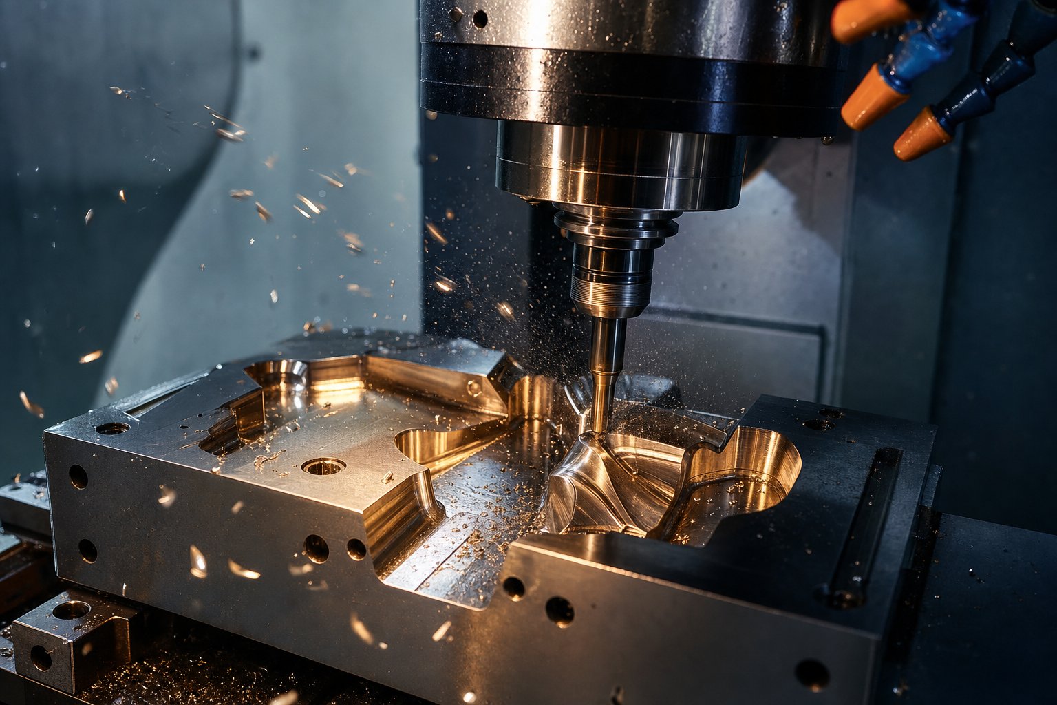
CNC Machining Processes That Shape Every Die Component
A block of D2 or M2 sitting on a pallet is just raw potential. Turning it into a functioning die component requires a deliberate sequence of CNC machining operations, each performed at a specific stage for a specific reason. The order matters as much as the operations themselves. Rough too aggressively and you introduce internal stresses that warp the part during heat treatment. Finish before hardening and you lose your precision when the steel moves during quench. Every metal stamping tool and die shop follows a machining logic built around one principle: remove the bulk while the steel is soft, harden it, then bring it to final size while it is hard.
Rough Milling and Semi-Finish Before Heat Treatment
Die components start their machining life in an annealed or pre-hardened state, typically around 20-30 HRC. At this softness, the material cuts easily, tools last longer, and material removal rates stay high. Roughing operations hog out the majority of excess stock, leaving 0.5 to 1.0 mm of material on all critical surfaces as a "finish allowance" for later operations.
Why leave that allowance? Two reasons. First, heat treatment causes dimensional movement. Even vacuum-hardened tool steel shifts slightly as its crystal structure transforms during quenching. Second, the roughing process itself generates residual stress from cutting forces and localized heat. If you machined to final size at this stage, you would watch those dimensions shift after hardening.
Between roughing and heat treatment, a stress-relief cycle at around 600-650 degrees Celsius relaxes the internal stresses created by aggressive cutting. Semi-finish passes then bring surfaces closer to final dimensions, typically within 0.2-0.3 mm, while maintaining a uniform stock condition that ensures even heat penetration during the subsequent hardening cycle. CNC turning handles round components like guide pins, bushings, and round punches at this stage, producing near-net-shape geometry before the steel transforms.
Finish Grinding and High-Speed Hard Milling After Hardening
Once heat treatment brings components to their working hardness of 58-65 HRC, the material behaves completely differently under a cutter. It is now an abrasive fortress that resists traditional machining. Two finishing strategies handle this challenge: precision grinding and high-speed hard milling.
Surface grinding brings flat components like die plates, backing plates, and wear strips to final thickness with flatness tolerances of +/- 0.005 mm or better. Cylindrical grinding finishes round components to diameter tolerances within microns. Grinding excels at producing geometric perfection on accessible surfaces. As precision machining specialists note, when a design requires flatness or parallelism within +/- 0.002 mm, grinding is the only logical choice, delivering surface finishes down to Ra 0.1 micrometers.
High-speed hard milling has emerged as a powerful complement to grinding. Using carbide or PCBN tooling at high spindle speeds, this process exploits adiabatic shear: the tool contact time is so brief that the majority of heat transfers into the chip rather than the workpiece. The result is efficient material removal from hardened steel without thermal damage to the component surface. Hard milling can remove material up to five times faster than grinding while generating compressive residual stress on the surface, which actually benefits fatigue life in stamping tooling subjected to cyclic loads.
The practical division between these methods is straightforward. Grinding handles flat datums, parallel surfaces, and simple cylindrical profiles. Hard milling tackles 3D contours, pocketed geometries, and complex cavity profiles that a grinding wheel physically cannot reach. Most die components require both: ground reference surfaces for assembly fit, and hard-milled contours for forming geometry. This hybrid approach is standard practice in metal stamping tooling production because each process covers geometries the other cannot.
5-Axis CNC for Complex Die Profiles
Not every die component can be finished with 3-axis work. When a forming punch has compound curves, or a die cavity features deep walls with drafted surfaces and tight radii, 3-axis milling forces compromises. The tool can only approach from above, requiring longer cutters that deflect under load and leaving scallop marks on angled surfaces that demand excessive hand polishing.
5-axis machining solves this by tilting the tool or the workpiece, allowing the cutter to maintain an optimal orientation relative to the surface being cut. According to machining capability comparisons, 5-axis mills achieve tolerances of +/- 0.0005 inches with surface finishes down to Ra 0.4 micrometers, and they machine complex 3D surfaces in a single setup that would require multiple repositionings on a 3-axis machine.
For tool and die stamping applications, 5-axis capability matters most in these situations:
- Deep draw die cavities with compound-curved walls that require short, rigid tooling oriented normal to the surface
- Progressive die forming stations with angled features that cannot be reached from a vertical approach
- Complex punch profiles where multiple undercut features need machining without re-fixturing
However, not every component justifies 5-axis time. Simple flat die plates, backing plates, and straight-walled inserts machine efficiently on 3-axis equipment at lower hourly rates. The decision comes down to geometry: if a feature requires repositioning or long-reach tooling on a 3-axis machine, 5-axis typically delivers better accuracy at lower total cost despite the higher machine rate. When building dies destined for a high-speed metal stamping machine, the dimensional precision achievable through 5-axis finishing directly translates to tighter part tolerances and longer intervals between maintenance.
The complete machining sequence for a typical die component, from raw block to polished insert ready for assembly, follows this progression:
- Rough mill all features in the soft (annealed) state, leaving 0.5-1.0 mm stock on critical surfaces
- Stress relieve at 600-650 degrees Celsius to release machining-induced residual stress
- Semi-finish to within 0.2-0.3 mm of final dimensions with uniform stock allowance
- Send to heat treatment for vacuum hardening and tempering to target hardness
- Finish grind reference surfaces and hard mill complex contours to final dimensions
- Final polish forming surfaces to required Ra values for material flow and part release
Each step gates the next. Skipping stress relief before heat treatment invites distortion. Hard milling before verifying post-heat-treatment dimensions wastes machine time on a part that may have moved beyond recoverable limits. The discipline of this sequence is what separates professional metal tool and die fabrication from shops that chase problems through rework.
Precision grinding and hard milling handle the majority of die geometries, but certain features push beyond what any rotating cutter or abrasive wheel can achieve. Sharp internal corners, narrow slots, and intricate through-profiles demand a completely different removal mechanism, one that cuts with electrical spark rather than mechanical force.
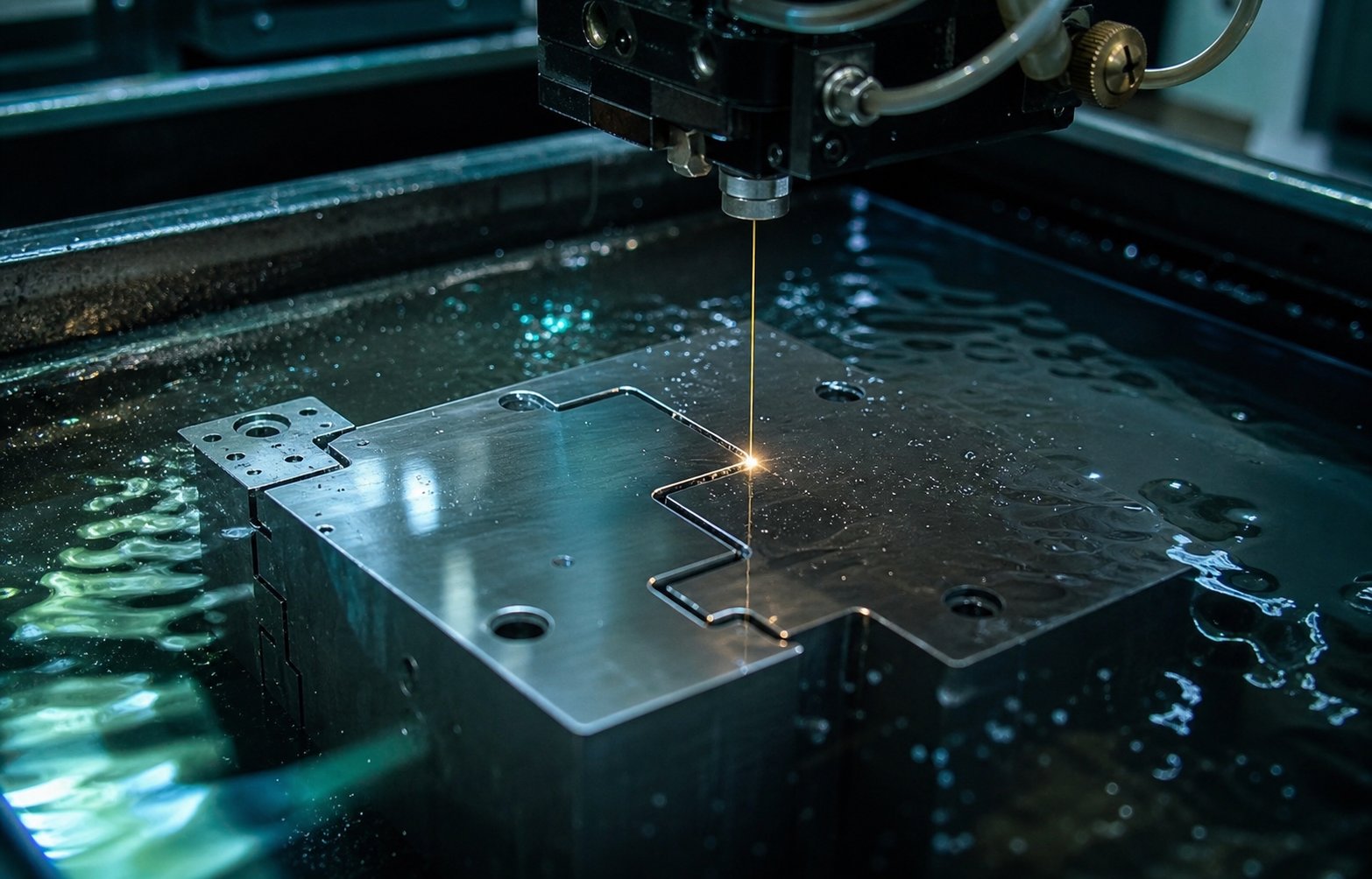
Wire EDM and Sinker EDM for Complex Die Geometries
A milling cutter, no matter how small its diameter, leaves a radius in every internal corner equal to its own size. A grinding wheel cannot reach inside a narrow slot. These physical limitations mean that certain stamping die components, particularly intricate sheet metal punches and dies, require a fundamentally different material removal process. Electrical discharge machining removes metal through controlled spark erosion rather than mechanical cutting force, producing geometries that no rotating tool can replicate.
Wire EDM for Precision Punch and Die Profiles
Wire EDM uses a thin brass or coated wire, typically 0.1 to 0.3 mm in diameter, as an electrode that cuts through the workpiece along a CNC-programmed path. The wire never contacts the material. Instead, rapid electrical discharges vaporize microscopic particles while deionized water flushes debris and cools the cut zone. Because the wire passes completely through the workpiece, wire EDM produces through-cut profiles with internal radii as small as the wire diameter itself, far sharper than any milling cutter can achieve.
For a sheet metal stamping die, wire EDM is the go-to process for cutting punch profiles, die openings, and clearance holes after heat treatment. You'll notice this is critical: cutting hardened tool steel at 60+ HRC is routine for wire EDM because material hardness has minimal influence on spark erosion. The process machines D2, M2, and even carbide with equal ease. Die stamp profiles that require tight clearance relationships between the punch and die opening, sometimes as little as 5-8% of material thickness per side, rely on wire EDM's ability to hold tolerances in the range of +/- 0.005 mm under controlled conditions.
Multiple skim passes progressively refine accuracy and surface finish. A rough cut removes the bulk of material, then two to four finishing passes shave microns at a time, improving both dimensional precision and surface quality with each pass. This makes wire EDM ideal for cutting the mating profiles of stamping die components where punch-to-die fit determines burr height on every stamped part.
Sinker EDM for Cavities and Complex Contours
Where wire EDM excels at through-cut profiles, sinker EDM handles blind cavities, 3D contours, and textured surfaces that a wire physically cannot produce. The process uses a custom-shaped electrode, typically machined from graphite or copper, that "sinks" into the workpiece through spark erosion. The electrode's shape directly corresponds to the cavity geometry you need, and as the process progresses, thousands of micro-sparks per second remove material with precision while hydrocarbon oil dielectric manages heat and debris.
In metal stamping die construction, sinker EDM finds its role in forming cavities with complex 3D surfaces, coining details, and embossing features that no milling cutter can reach without deflection. It also creates textured surfaces on die stamp faces where controlled roughness aids material flow during forming. The process generates no mechanical force on the workpiece, which means thin die sections and delicate features remain undistorted during machining.
The tradeoff is speed and tooling cost. Each electrode must be custom-machined to match the desired cavity, and electrodes wear during use, sometimes requiring multiple copies for a single feature. Cycle times run slower than wire EDM for equivalent material volumes. But for blind cavities in hardened steel, sinker EDM remains the only practical option.
| Parameter | Wire EDM | Sinker EDM |
|---|---|---|
| Achievable Tolerance | +/- 0.002 to 0.005 mm | +/- 0.005 to 0.025 mm |
| Surface Finish (Ra) | 0.1 to 0.8 micrometers | 0.4 to 3.2 micrometers |
| Best Geometry Types | Through-cut profiles, straight-walled openings, punch outlines | Blind cavities, 3D contours, textured forming surfaces |
| Typical Cycle Time | 2 to 12 hours per profile (depending on thickness and passes) | 4 to 40+ hours per cavity (depending on depth and complexity) |
Lapping and Polishing for Surface Quality
EDM leaves a characteristic recast layer on machined surfaces, a thin zone of re-solidified material that can be harder and more brittle than the parent steel. For cutting components like punches and die openings, this layer is typically acceptable or even beneficial. For forming surfaces where sheet metal must flow smoothly under pressure, it needs removal.
Lapping uses fine abrasive compounds on flat or contoured laps to remove material at the sub-micron level, producing flatness and surface finishes that grinding alone cannot match. It is the standard method for bringing critical mating surfaces of a sheet metal die to the geometric perfection required for even contact under press load.
Polishing addresses forming surfaces specifically. As experienced die makers at The Fabricator note, polishing in the direction of metal flow reduces friction and helps sheet metal move through draw and form stations without galling. However, not every surface benefits from a mirror finish. Rougher draw-quality steels actually perform better against slightly textured tooling because their micro-valleys trap lubricant. The decision of where to polish and where to leave controlled texture on a sheet metal stamping die depends on the specific material being stamped and the type of forming operation at each station.
Together, EDM and surface finishing give die makers control over geometries and surface conditions that CNC machining alone cannot deliver. These processes complete the shaping phase of die construction. But raw geometry and surface finish are only part of what makes stamping die components perform under production loads. The steel itself must be transformed through heat treatment and protective coatings to resist the millions of impacts, abrasive cycles, and thermal events that production stamping demands.
Heat Treatment and Surface Coatings That Extend Die Life
Machining gives a die component its shape. Heat treatment gives it the mechanical properties to survive production. Without proper hardening and tempering, even the most precisely machined D2 punch would deform under stamping loads within thousands of hits. And without protective coatings, adhesive wear would destroy forming surfaces long before abrasion ever became the limiting factor. These two post-machining steps, heat treatment and coating, are where die longevity is won or lost.
Vacuum Hardening and Tempering Sequences
Vacuum hardening heats tool steel to its austenitizing temperature inside a low-pressure chamber, then quenches it using high-pressure inert gas. The vacuum environment prevents oxidation and decarburization, preserving the surface integrity that was painstakingly created during finish machining. Parts come out clean and dimensionally stable, with minimal distortion compared to atmosphere-based methods.
A single quench cycle is never the full story. Tempering follows hardening, typically in two or three cycles at progressively decreasing temperatures. Each temper transforms retained austenite into stable martensite, relieves internal stress from the quench, and tunes the final balance between hardness and toughness. Skipping a temper cycle leaves unstable microstructures that can shift dimensionally during production, causing progressive tolerance loss that is difficult to diagnose.
Cryogenic treatment pushes this transformation further. By cooling components to approximately minus 300 degrees Fahrenheit using liquid nitrogen in a controlled descent over several hours, cryogenic processing converts residual austenite that standard tempering leaves behind. Research published in the International Journal of Engineering Science documented that a scientifically controlled deep cryogenic process produces use-life increases exceeding 200 percent across multiple tooling applications. The molecular-level changes, including improved carbide distribution and complete martensitic transformation, reduce the coefficient of friction and enhance dimensional stability permanently. For stamping dies expected to run millions of cycles, cryogenic treatment after conventional heat treatment can double or triple useful die life before resharpening becomes necessary.
PVD and CVD Coatings That Reduce Wear and Galling
Heat treatment optimizes the bulk material. Coatings protect the surface where tool-to-sheet contact actually occurs. Physical vapor deposition (PVD) and chemical vapor deposition (CVD) apply thin ceramic layers, typically 2 to 5 microns thick, that dramatically reduce friction and resist material transfer from the stamped sheet onto die surfaces.
Why does this matter? When stamping stainless steel, the material's tendency to work-harden and gall creates adhesive buildup on die surfaces that quickly degrades part quality. A trial at Ford Motor Company's stamping plant, reported by Deakin University researchers, found that TiCN-coated dies increased die life by a factor of more than 20 compared to uncoated polished surfaces when stamping galling-prone materials. The coating postponed the critical material-transfer stage indefinitely within the trial's 20,000-cycle test window.
Each coating type targets a specific wear mechanism:
- TiN (Titanium Nitride): General-purpose wear protection with hardness around 2000-2500 HV. Cost-effective for mixed-material stamping at moderate speeds and volumes.
- TiCN (Titanium Carbonitride): Higher hardness and lower friction than TiN. Excels against abrasive materials including stainless steel metal stamping applications where work-hardened surfaces accelerate edge wear.
- TiAlN (Titanium Aluminum Nitride): Tolerates temperatures above 800 degrees Celsius by forming a protective aluminum oxide layer under heat. Suited for high-speed stamping and applications where lubricant breakdown creates elevated tool temperatures.
- DLC (Diamond-Like Carbon): Extremely low friction coefficient of approximately 0.1 to 0.15, preventing adhesive material pickup. The primary choice for aluminum stamping dies and aluminum stamping tools where galling of stamped aluminum onto die surfaces is the dominant failure mode rather than abrasive wear.
Coating selection connects directly to the stamped material. For 316 stainless steel stamping, where both abrasion and adhesion attack tooling simultaneously, TiCN or TiAlN provide the hardness and chemical inertness needed to resist galling at forming stations. For aluminum metal stamping, DLC's ultra-low friction prevents the soft material from bonding to tool surfaces, keeping part surfaces clean and die maintenance intervals long. Performance comparisons confirm that DLC's friction reduction greatly lowers cutting resistance and prevents chip adhesion when machining or forming soft metals like aluminum and copper.
The compounding effect of these decisions is significant. A die built from the correct tool steel grade, properly vacuum-hardened with cryogenic treatment, and coated with the right ceramic layer can run three to five times longer than one where any single step was compromised. That multiplier translates directly into fewer production stoppages, lower cost per hit, and more consistent stamped part quality across the entire die life. But quantifying that performance requires rigorous measurement at every stage, from the first dimensional check after heat treatment through the final inspection of trial-stamped parts.
Quality Control from First Cut to Trial Stamping
A die can be machined from premium tool steel, heat-treated flawlessly, and coated with the ideal ceramic layer, yet still fail in production if nobody verified dimensions between phases. Quality control in precision die stamping is not a final checkpoint. It is a series of gates embedded throughout the entire manufacturing sequence, each one confirming that the component is ready to advance. Skip a gate and you risk compounding an early error through every subsequent operation until it surfaces as scrap parts on the press floor.
CMM Inspection and Surface Roughness Verification
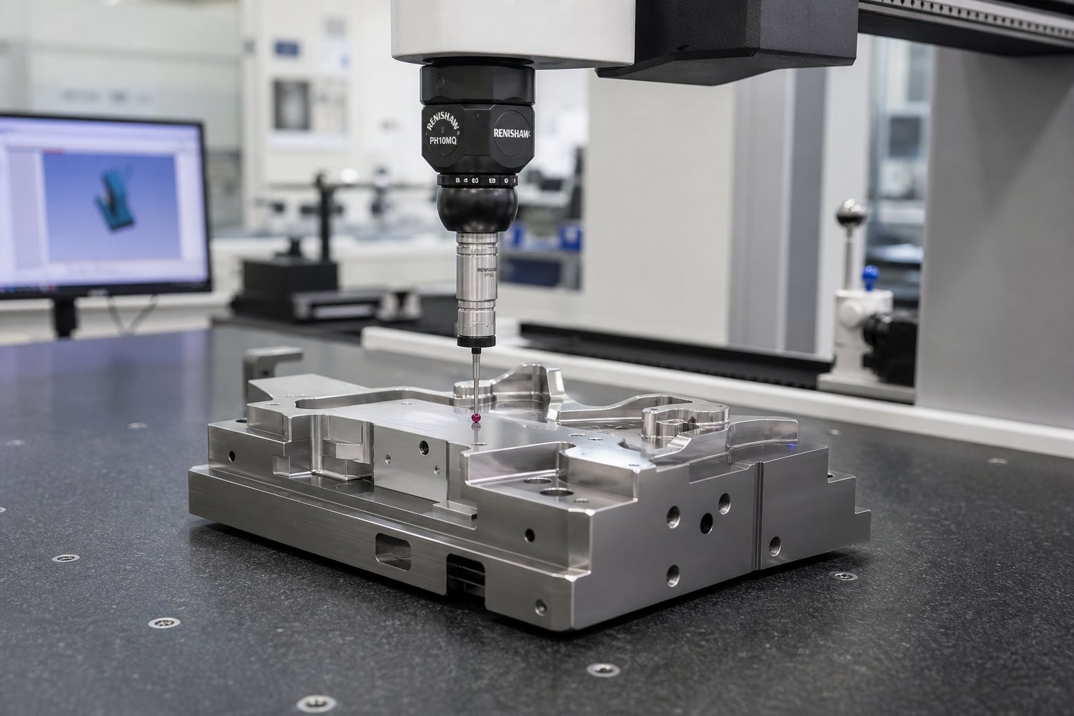
Coordinate measuring machines sit at the center of dimensional verification for stamping die components. A CMM probe touches or scans critical features, capturing XYZ coordinate data and comparing it against the 3D CAD model. For die inserts, punches, and cavity blocks, the CMM checks positional accuracy of holes, profile conformance of contoured surfaces, and geometric relationships like flatness, parallelism, and perpendicularity that determine how mating parts fit together during assembly.
When do these measurements happen? Not just at the end. In-process checks after rough machining confirm that enough stock remains on all critical surfaces before stress relief and semi-finishing. After heat treatment, a CMM re-check verifies how much dimensional movement occurred during hardening, which tells the finish machinist exactly how much material to remove and where. Post-finish-grind inspection generates the final conformance report that releases each component for assembly. As Moeller Precision Tool details, precision tooling manufacturers hold tolerances as tight as 0.0002 inches, using CMM devices alongside optical comparators and profile measurement systems to verify conformance at every stage.
Surface roughness measurement complements dimensional data. A profilometer traces the machined or polished surface and reports Ra (arithmetic average roughness) and Rz (average peak-to-valley height) values. Why does this matter for the metal stamping process? Because surface finish on forming steels controls friction, material flow, and part release. A forming punch specified at Ra 0.2 micrometers that actually measures Ra 0.8 will produce parts with visible drag marks and inconsistent wall thickness. Verifying surface roughness before assembly prevents these downstream quality issues from ever reaching the press.
Hardness testing forms another critical gate, particularly after heat treatment. Rockwell hardness measurements at multiple locations on each component confirm uniform transformation. A punch that reads 60 HRC at the face but 56 HRC at its base indicates incomplete hardening, potentially from inadequate soak time or quench inconsistency. Industry inspection protocols specify that hardness values must fall within a defined range because too-low hardness leads to rapid wear, while too-high hardness creates brittleness and fracture risk under stamping loads.
Functional fit checks complete the pre-assembly verification. Mating components, such as a punch and its corresponding die opening, are physically assembled on a bench to verify clearance relationships, sliding fits on guide elements, and interference conditions on press-fit details. Optical comparators overlay magnified component profiles against the design geometry to catch subtle deviations that CMM point probing might miss. These fit checks confirm that individual components will function as a coordinated system once bolted into the die set.
Trial Runs and First-Article Part Measurement
Assembly inspection confirms that the die looks correct. Trial stamping proves that it works. The completed die is mounted in a press, strip material is fed, and the first parts come off the tool. This is the moment that validates every upstream decision, from CAD geometry through machining and heat treatment. A successful trial produces metal stamping parts that meet print dimensions, exhibit clean edges, and form without cracking, wrinkling, or excessive springback.
Trial runs follow a structured protocol. The die is set at the calculated shut height, fed at a controlled speed, and run at reduced tonnage initially while operators observe strip progression, listen for abnormal noise, and inspect the first few parts visually. Strip feeding stability, pilot engagement, and stripper function are all monitored in real time. If the die is a progressive type, each station's work is evaluated independently by examining partially completed parts at intermediate stations before the final separation cut.
First-article inspection measures trial-stamped parts against the engineering drawing using the same CMM equipment that validated the die components themselves. Every critical dimension, GD&T callout, and surface specification is recorded. The resulting report either confirms conformance or identifies deviations that require die adjustment. Common adjustments include shimming form stations to correct angular springback, re-polishing surfaces that show drag marks, or adjusting punch-to-die clearance at stations producing excessive burr. As die trial specialists emphasize, a thorough first-article inspection provides detailed measurement reports, physical trial samples, and documentation that confirms the die is production-ready before shipment.
Every metal stamped part that leaves a production press inherits the quality built into its die. Trial stamping is where that inheritance is proven. A die that passes first-article inspection with all dimensions within tolerance and all surfaces free of defects represents validated tooling, ready to produce stamped metal parts consistently across hundreds of thousands or millions of cycles.
The full inspection gate sequence, from first chip to validated production tool, follows this progression:
- In-process dimensional checks after rough and semi-finish machining to verify stock allowance
- Post-heat-treatment hardness verification and CMM re-measurement for dimensional movement
- Final CMM report after finish grinding and hard milling confirm all features within tolerance
- Assembly fit check of mating components, clearance verification, and optical profile comparison
- Trial stamping in a production-equivalent press with controlled parameters
- First-article inspection measuring stamped parts against engineering prints with full dimensional reporting
Each gate must pass before work advances. This discipline prevents the most expensive quality failure in die making: discovering a problem after all downstream operations have been completed on a flawed component.
Manufacturers who cover this full lifecycle under one roof, from feasibility assessment and CAE simulation through precision machining, trial runs, and CMM inspection, eliminate the communication gaps that arise when responsibilities split across multiple vendors. YICHEN's stamping die process exemplifies this integrated approach, validating dies through every stage described here so that tooling engineers and sourcing managers receive production-ready tooling backed by documented inspection data at each gate. For teams moving from research into active RFQ development, partnering with a single-source provider that owns the entire QC chain reduces risk and compresses timelines significantly.
Inspection and validation close the manufacturing loop, but the real measure of a stamping die is how all these individual decisions, from CAD geometry through material selection, machining sequence, heat treatment, and quality verification, compound into long-term production performance.
Bringing It All Together from Feasibility to Production
You have now walked through every phase of making a metal stamping die: digital design and simulation, material selection, CNC machining, EDM processing, heat treatment, coating, and quality verification. Each section covered an isolated process. In reality, these steps do not operate independently. They compound. A design decision in CAD ripples forward through material choice, machining strategy, and ultimately into the stamped part quality your press produces at full speed. Understanding how that compounding works is what separates a stamping die that delivers 500,000 reliable hits from one that degrades after 10,000.
How Each Manufacturing Decision Compounds into Die Performance
Think of the die process as a chain of multipliers rather than a sequence of additions. Choosing a proper tool steel grade does not simply add durability. It multiplies the benefit of every downstream step. Vacuum-hardening a well-selected D2 insert yields better results than vacuum-hardening a marginal grade. Applying TiCN coating to a properly tempered and polished surface delivers its full friction-reduction potential. Apply that same coating to a surface with residual stress from skipped tempering cycles, and it spalls off within thousands of strokes.
The same logic works in reverse. A shortcut at any stage divides the performance of everything that follows. Rushing CAE simulation and missing a springback prediction means the die geometry is wrong before machining even starts. Under-specifying tool steel for a stainless application means coatings fight a losing battle against substrate deformation beneath them. Skipping stress relief before heat treatment introduces warpage that finish grinding cannot fully recover. Each compromise subtracts from die life, part quality, and production uptime.
What actually separates a die that runs 100,000+ hits from one that fails early? Typically not a single catastrophic error, but an accumulation of marginal decisions:
- Design shortcuts: Insufficient simulation leads to trial-and-error corrections on hardened steel, weakening components through repeated modification
- Material compromises: Choosing A2 where D2 or carbide is warranted saves upfront cost but doubles resharpening frequency and press downtime
- Machining sequence violations: Finishing before proper stress relief introduces dimensional instability that worsens under cyclic press loads
- Heat treatment gaps: Missing a temper cycle or skipping cryogenic treatment leaves retained austenite that transforms unpredictably during production, causing progressive tolerance drift
- Inspection lapses: Releasing components without verifying post-heat-treatment dimensions means assembling a die from parts that may already be out of specification
The metal stamping manufacturing process rewards discipline at every gate. Cost and timeline expectations scale accordingly. A simple single-station blanking die might require 4 to 6 weeks and $5,000 to $15,000 in tooling investment. A moderate progressive die with 8 to 12 stations typically demands 8 to 12 weeks and $25,000 to $60,000. Complex automotive progressive or transfer dies with tight tolerances, multiple forming stations, and high-volume life requirements can exceed 16 weeks and $100,000 in tooling cost. These ranges reflect not just machining hours, but the cumulative engineering, simulation, inspection, and trial effort that validates each tool for its intended production life.
Every step in making a stamping die, from CAD geometry to final coating, is a decision that either adds or subtracts from die life, part quality, and production efficiency. There are no neutral choices in the die and stamping construction process.
Moving from Research to an RFQ-Ready Die Solution
If you have read this far, you likely fall into one of two categories. Either you are building internal knowledge to evaluate suppliers more effectively, or you are actively approaching an RFQ for a custom metal stamping die and want to understand what questions to ask and what capabilities to verify. Both paths benefit from the same principle: the stamping manufacturing process works best when a single partner owns the full chain from feasibility through validated production tooling.
Fragmented sourcing, where design happens at one firm, machining at another, and tryout at a third, introduces handoff risk at every transition. Dimensional intent gets lost between CAD files and machine operators. Heat treatment specifications get simplified for convenience. Trial results do not feed back efficiently into design corrections. The dies and stamping tools that perform best in long production runs almost always come from integrated programs where every phase informs the next without communication gaps.
For sourcing managers and tooling engineers ready to move from research into active quoting, look for a partner whose capabilities span the entire lifecycle covered in this article: feasibility assessment, CAE simulation for forming and springback, precision CNC machining and EDM, controlled heat treatment, trial stamping in production-representative conditions, and CMM-documented first-article inspection. YICHEN's custom stamping die solutions cover exactly this scope, providing an end-to-end metal stamping resource for teams that need validated tooling delivered RFQ-ready, backed by documented quality data at every manufacturing gate.
The knowledge in this article gives you the vocabulary and framework to evaluate any die supplier's process critically. You now understand why certain steps cost what they do, why timelines stretch at certain complexity thresholds, and why the cheapest quote rarely delivers the lowest cost per hit over a die's full production life. That understanding is the foundation for making informed sourcing decisions in any dies and stamping procurement conversation.
FAQs About Making Metal Stamping Dies
1. How long does it take to make a metal stamping die?
Timelines depend on complexity. A simple single-station blanking die typically requires 4 to 6 weeks. A moderate progressive die with 8 to 12 stations takes 8 to 12 weeks. Complex automotive progressive or transfer dies with tight tolerances and multiple forming stations can exceed 16 weeks. These timelines include engineering, simulation, machining, heat treatment, and trial validation phases.
2. What materials are used to make stamping dies?
Stamping dies are built primarily from tool steel grades selected based on the sheet metal being stamped. Common choices include D2 for abrasive wear resistance, A2 for balanced toughness and hardness, S7 for impact-heavy applications, M2 for high compressive loads, and tungsten carbide inserts for ultra-high-volume runs or highly abrasive materials like stainless steel. Each grade occupies a different position on the hardness-toughness spectrum.
3. What is the difference between a progressive die and a transfer die?
Progressive dies keep parts connected to a carrier strip as it advances through multiple stations with each press stroke, making them ideal for smaller, high-volume components like connectors and brackets. Transfer dies cut blanks free at the first station and mechanically move them between independent stations using grippers. Transfer dies suit large parts, deep-drawn shells, and geometries that cannot remain attached to a strip during forming, such as automotive body panels.
4. How does heat treatment affect stamping die performance?
Heat treatment transforms tool steel from a machinable state into a hardened working tool capable of withstanding millions of press cycles. Vacuum hardening followed by multiple tempering cycles creates a stable martensitic structure. Adding cryogenic treatment can increase die life by over 200 percent by converting retained austenite and improving carbide distribution. Without proper heat treatment, even precisely machined components would deform or wear rapidly under production stamping loads.
5. Who can manufacture a complete stamping die from design to production validation?
Integrated die manufacturers that own the full process chain, from feasibility assessment and CAE simulation through CNC machining, EDM, heat treatment, trial stamping, and CMM inspection, deliver the most reliable results. YICHEN offers this end-to-end capability for custom stamping die solutions, providing documented quality verification at every manufacturing gate so sourcing managers and tooling engineers receive production-ready tooling without handoff risks between multiple vendors.


