


What Progressive Die Stamping Is and Why It Matters
You're drafting an RFQ for a high-volume stamped component, and you realize the spec sheet feels thin. The tolerances are vague, the material callout is generic, and the volume projections are ballpark at best. Sound familiar? That gap between what you know and what your supplier needs is exactly where projects stall, costs inflate, and timelines slip. Understanding professional progressive die & stamping at an engineering level closes that gap.
Defining Progressive Die Stamping
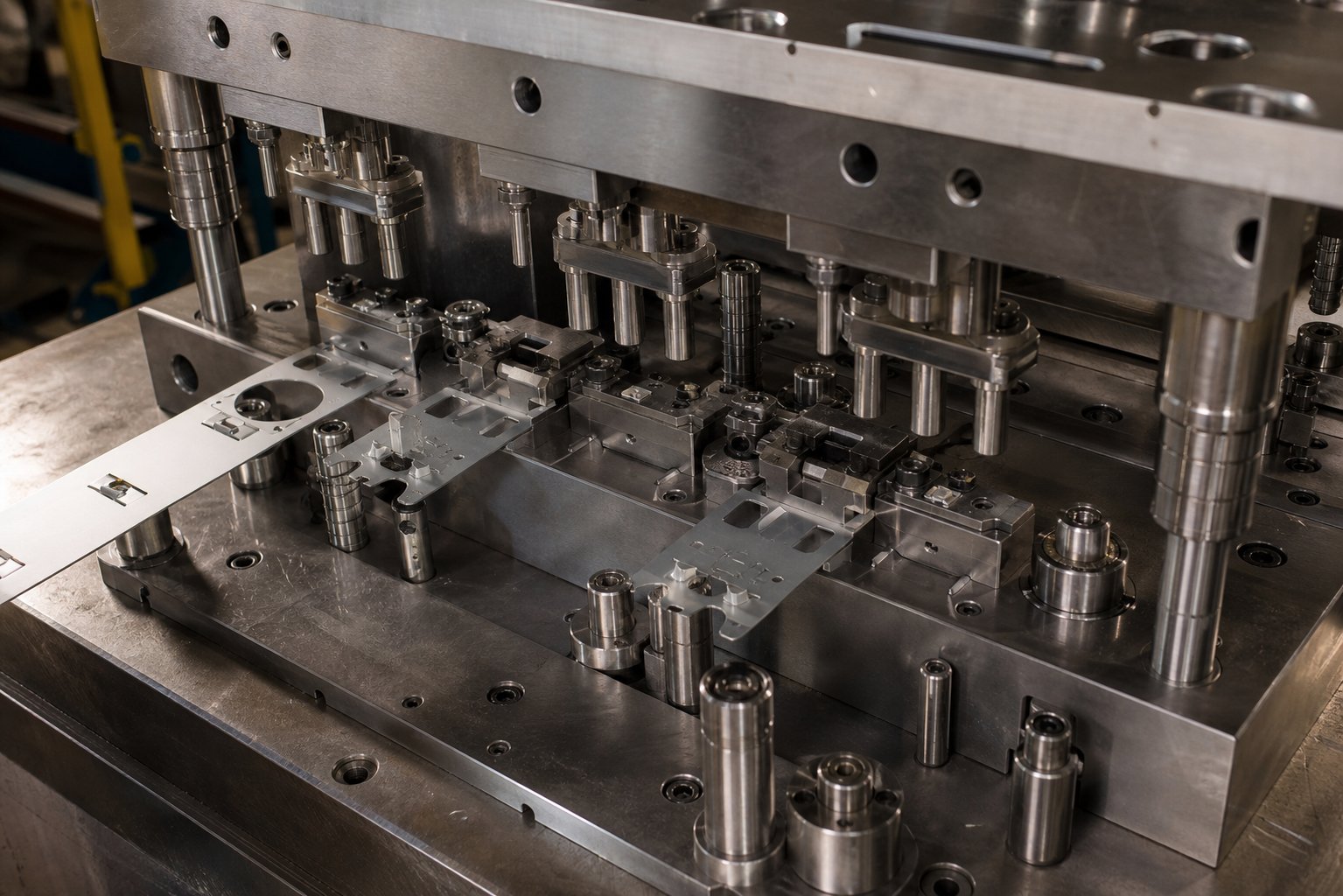
A progressive die is a precision tool set containing multiple sequential workstations within a single press, through which a continuous metal strip advances one fixed pitch per stroke. Each station performs a distinct operation such as piercing, forming, or blanking, and the finished part is separated from the carrier strip only at the final stage.
So what is a progressive die in practical terms? It's an automated production system engineered to transform flat coil stock into complex, finished components at speeds that can exceed hundreds of strokes per minute. Unlike single-station tooling or transfer setups, progressive stamping keeps the workpiece attached to the strip throughout the entire forming sequence. This eliminates part handling between operations, reduces cumulative positioning error, and enables the kind of throughput that makes high-volume programs economically viable.
The term "prog die" is common shorthand on shop floors and in procurement discussions, but the engineering behind progressive tool and die systems is anything but simple. Every station, every clearance, and every material interaction represents a design decision that directly affects part quality, tool life, and per-piece cost.
Who This Resource Serves
This article is built for production engineers specifying parts for progressive die & stamping programs and for procurement professionals evaluating supplier capability. Whether you're new to progressive stamping and need foundational clarity, or you're experienced but looking for deeper guidance on strip layout, tolerance strategy, or supplier qualification, the content ahead bridges that middle ground. Most available resources either oversimplify the process or assume expert-level familiarity. Here, you'll find engineering-first detail covering die construction, material selection, design sequencing, quality control, cost analysis, and maintenance planning, all structured to help you write better specs and ask sharper questions of your tooling partners.
The mechanics of how a progressive die actually cycles through each stroke, and what happens at every station along the strip, reveal why small design decisions cascade into major production outcomes.
How the Progressive Die Stamping Process Works
Picture a coil of sheet metal, weighing hundreds or even thousands of pounds, sitting on an uncoiler. Within minutes, that raw material will transform into dozens of finished parts per minute, each one dimensionally identical to the last. The progressive die stamping process achieves this through a tightly choreographed sequence of mechanical events that repeats with every press stroke. Understanding each step helps you specify parts more effectively and spot potential issues before they become production problems.
Strip Progression and Station Sequencing
The metal strip's journey begins at the uncoiler, passes through a straightener to eliminate coil set, and enters a servo or mechanical feeder that advances the strip by a precise, fixed distance called the feed pitch. This pitch remains constant throughout the run, and it determines how far the strip moves between each press stroke.
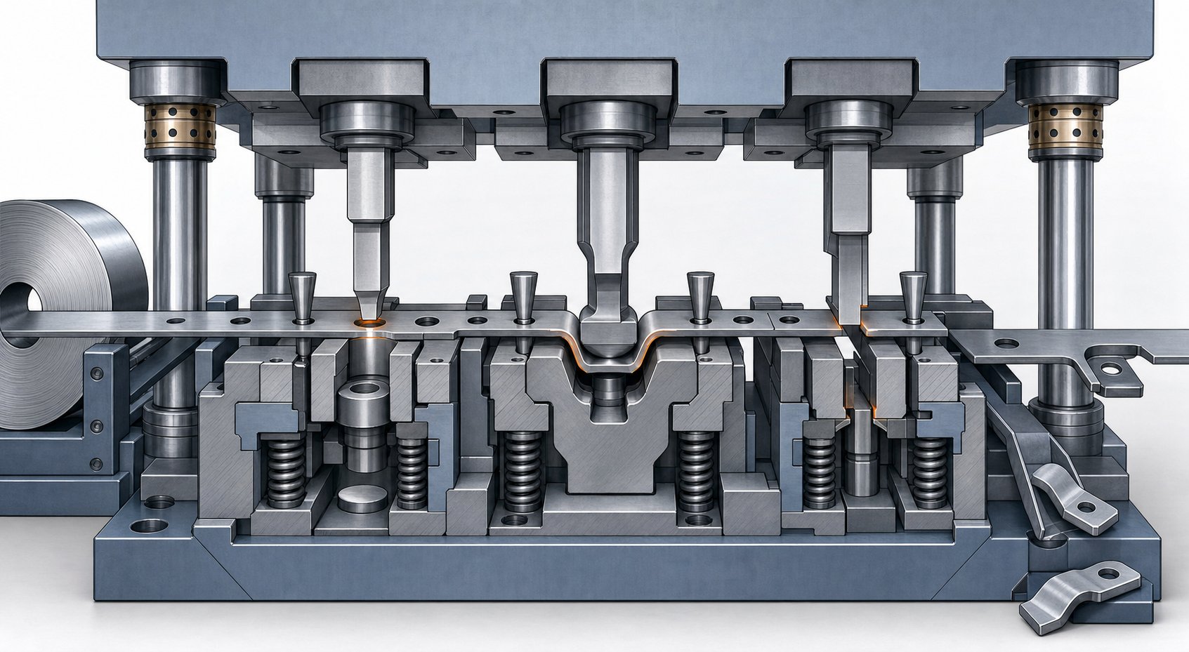
Once inside the die, the strip encounters a series of stations arranged in sequence. Each station performs one or more operations on the material. A typical progressive stamping process might include piercing at station one, notching at station two, forming at stations three and four, and cutoff at station five. The exact count depends on part complexity; some dies contain fewer than five stations while others exceed twenty.
Registration accuracy is what separates a good progressive die from a great one. Early stations pierce small, precisely located pilot holes into the strip. At every subsequent station, conical pilot pins enter these holes just before the press reaches bottom dead center. The tapered geometry of these pilots pulls the strip into exact alignment, correcting any minor feed inaccuracies. Typical pilot-to-hole clearance runs around 0.0005 to 0.001 inches for precision work, tight enough to hold positional accuracy across the entire strip length.
This pilot registration system means that even at high speed, every feature on the finished part maintains its relationship to every other feature. Without it, tolerances would drift station by station, and the cumulative error at the final cutoff would render parts unusable.
The operations available at each station span a wide range:
- Piercing - creates holes, slots, or openings by shearing material away
- Blanking - cuts the outer profile of the part or a preform shape
- Forming - creates three-dimensional geometry like channels, ribs, or functional profiles
- Drawing - stretches material into cup or shell shapes through controlled metal flow
- Coining - compresses material to achieve precise thickness, flatness, or surface detail
- Bending - forms angles, tabs, clips, or spring features
- Lancing - partially cuts and bends a feature without fully removing material
- Cutoff - separates the finished part from the carrier strip at the final station
Throughout this entire progression, the part remains connected to the carrier strip. That carrier acts as both a transport mechanism and a reference structure, holding the workpiece stable as it moves from station to station. Only at the final cutoff does the finished component separate and eject from the die.
Press Mechanics and Stroke Rates
The progressive die press provides the driving force behind every operation. A mechanical press converts rotary motor energy into linear ram motion, delivering a fixed tonnage at a specific point in its stroke. The press ram descends, engages the upper die half with the strip and lower die, performs all station operations simultaneously, then retracts. During the return stroke, the feeder advances the strip one pitch forward, and the cycle repeats.
How fast can this cycle run? That depends on part complexity. Simple flat stampings with only piercing and blanking operations can achieve high speed progressive die stamping rates exceeding 1,500 strokes per minute (SPM). Parts requiring deep drawing or complex multi-stage forming typically run under 100 SPM because the material needs more time to flow properly and the strip requires careful control during forming. Most production parts fall somewhere in between, with 200 to 800 SPM being common for moderately complex components.
Several factors determine the achievable speed on any given progressive stamping press:
- Number of forming stations and depth of draw
- Material type and thickness (thicker or harder materials demand slower speeds)
- Strip lift height required to clear lower die details between strokes
- Feed system capability (servo feeds generally outperform mechanical feeds at higher speeds)
- Scrap ejection reliability at speed
- Die protection sensor response time
A single press stroke cycle on a die stamping press follows this sequence:
- The feeder advances the strip forward by exactly one pitch distance.
- Pilot pins engage pre-pierced holes, pulling the strip into final registration.
- The press ram descends, and the stripper plate contacts the strip to hold it flat against the die surface.
- Punches and forming tools engage the material, performing all station operations simultaneously.
- The ram reaches bottom dead center, completing cutting, forming, and coining operations.
- The ram retracts; the stripper plate holds the strip down, pulling it free from the punches.
- Lifter pins raise the strip off the lower die details, clearing formed features for the next advance.
- Scrap slugs drop through die openings into chutes below.
- The finished part ejects or drops from the final station.
- The feeder indexes the strip forward, and the cycle begins again.
Every one of these steps happens within a fraction of a second at production speed. The mechanical precision required to coordinate strip feed timing, pilot engagement, press stroke position, and scrap ejection across hundreds or thousands of cycles per minute is what makes progressive die tooling one of the most engineered production systems in metalworking.
The reliability of this cycle, stroke after stroke, depends heavily on the physical construction of the die itself. The components that maintain alignment under these repeated high-speed impacts determine whether a tool produces quality parts for millions of cycles or begins drifting after the first hundred thousand.
Die Construction and Tooling Components Engineers Must Know
A progressive die can cycle thousands of times per minute, but that speed means nothing if the tool's physical structure can't maintain alignment under relentless impact loading. Every stamping die is an assembly of interdependent components, and the quality of each one directly governs part accuracy, tool life, and overall uptime. When you're evaluating a metal stamping die for a production program, you need to understand what's inside it and why each element matters.
Think of the stamping die set as a precision framework. The upper and lower die shoes form the backbone. Guide pins and bushings keep those halves tracking in perfect parallel. Stripper plates manage material control. Punch retainers, die inserts, and backing plates handle the actual work of cutting and forming. Remove or degrade any single element, and the entire system drifts out of spec.
Upper and Lower Die Assembly Components
Each component in the progressive die tooling assembly serves a specific mechanical purpose. The table below breaks down the major stamping die components, what they do, what they're made from, and how they typically fail in production.
| Component | Function | Typical Material | Common Failure Mode |
|---|---|---|---|
| Die Shoes (Upper & Lower) | Provide rigid mounting platforms for all working components; absorb and distribute press forces | Medium carbon steel (1045, 4140) or cast iron for large dies | Deflection under load, mounting slot wear |
| Guide Pins & Bushings | Maintain precise alignment between upper and lower die halves throughout the press stroke | Hardened tool steel pins; bronze or ball-bearing cage bushings | Galling, adhesive wear, or seizure from contamination or inadequate lubrication |
| Stripper Plates | Hold strip flat during cutting, strip material from punches on the return stroke | Alloy steel, often hardened; spring-loaded for progressive applications | Surface wear, loss of flatness, spring fatigue |
| Punch Retainers | Secure and locate punches in precise position within the upper die assembly | Hardened tool steel | Bore wear allowing punch drift, retention failure under impact |
| Die Inserts (Buttons) | Provide the female cutting or forming geometry that punches engage against | D2 tool steel, carbide (tungsten) for high-volume or abrasive materials | Edge chipping, abrasive wear, cracking from fatigue |
| Backing Plates | Prevent punches and inserts from being driven into the softer die shoe under repeated impact | Hardened tool steel | Indentation, mushrooming from concentrated forces |
| Pilot Assemblies | Engage pre-pierced holes to register the strip at exact position before each operation | Hardened tool steel or carbide tips | Tip wear, bending from misaligned strip, breakage |
These components don't work in isolation. The die shoes provide the stable foundation that guide pins reference. Guide pins maintain the alignment that punch-to-die clearances depend on. Backing plates protect the shoes from the concentrated forces that punches transmit. It's a chain of precision, and any weak link compromises everything downstream.
How Component Quality Affects Part Accuracy
Three relationships in a progressive die determine whether your parts come out in spec or out of tolerance: guide pin clearance, stripper plate flatness, and punch-to-die alignment.
Guide pin clearance controls how precisely the upper die tracks relative to the lower die. Ball-bearing guide systems hold tighter running clearances than plain friction pins, which is why high-speed progressive dies almost always use ball-cage assemblies. If guide pin wear opens up even a few thousandths of an inch of play, the entire upper half shifts laterally during the stroke. That shift translates directly into uneven burr, inconsistent formed features, and positional drift on pierced holes.
Stripper plate flatness determines how evenly the strip is held during cutting and forming. A warped or worn stripper allows the material to lift unevenly as punches engage, which introduces variability in cut quality and can cause slug pulling. Spring-loaded strippers need uniform spring force across the plate surface; a single weak or broken spring creates a local pressure deficit that shows up as inconsistent burr height.
Punch-to-die alignment is where everything converges. The clearance between a cutting punch and its matching die insert is typically expressed as a percentage of material thickness, often in the range of 5 to 12 percent per side depending on material type. If alignment drifts due to worn guides, deformed retainers, or a shifted insert, clearance becomes uneven around the punch perimeter. One side cuts too tight, causing secondary shear and premature edge wear. The opposite side cuts too loose, producing excessive rollover and burr.
This is where the choice between carbide and tool steel inserts becomes a meaningful engineering decision rather than a simple cost comparison. Progressive carbide stamping dies use tungsten carbide inserts for stations that experience the highest wear, particularly when stamping abrasive materials like stainless steel or silicon steel. Carbide offers extreme hardness and wear resistance, which means cutting edges stay sharp far longer, maintaining consistent clearance geometry across millions of hits. The trade-off is lower toughness; carbide inserts are more prone to chipping under shock loads or if alignment is imperfect.
Tool steel inserts, typically D2 or M2 grades, provide a better balance of toughness and wear resistance. They're forgiving of slight misalignment and easier to resharpen during maintenance cycles. For short- to medium-volume production runs or less abrasive materials like copper and brass, tool steel delivers excellent performance at lower initial cost.
The practical implication for your RFQ? Specify insert material based on your production volume, workpiece material, and expected die life. A supplier building a progressive die for 50 million hits in stainless steel needs carbide at critical stations. A die running 500,000 hits in brass may perform perfectly with well-maintained D2 inserts. Asking the right questions about these stamping die components during the quoting phase saves you from discovering material mismatch issues after tool tryout.
The die's physical construction sets the ceiling for what's achievable in terms of precision and longevity. But the workpiece material itself pushes back against that ceiling, influencing how hard each station works, how fast tooling wears, and which design compromises become necessary.
Material Selection and Compatibility for Progressive Stamping
Your die can be perfectly engineered, built with carbide inserts and ball-cage guides, and still produce scrap if the material running through it wasn't properly accounted for during design. Progressive metal stamping is a partnership between tool and workpiece. The strip's mechanical properties dictate station count, forming limits, press tonnage, tool wear rates, and ultimately the cost per part. Yet material callouts on RFQs are often reduced to a grade designation and a thickness, with no discussion of the engineering trade-offs that grade implies.
Choosing progressive stamping materials isn't about picking the cheapest option that "works." It's about understanding how a material's behavior under deformation shapes every downstream decision in the die design.
Material Properties That Drive Die Design
Three material characteristics exert the most influence on how a progressive die is designed and how it performs in production: yield strength, elongation percentage, and work-hardening rate.
Yield strength determines the force required to permanently deform the material. Higher yield strength means higher tonnage demands at every forming station. When you specify a high-strength stainless steel instead of a low-carbon steel, you're not just changing the strip, you're increasing press load requirements, demanding heavier die shoes to resist deflection, and potentially reducing achievable stroke rates because the press must deliver more energy per cycle.
Elongation percentage tells you how far the material can stretch before fracturing. This directly sets your forming severity limits. A material with 40% elongation gives die designers room to incorporate deeper draws and tighter bends in fewer stations. A material with 8% elongation requires gentler forming distributed across more stations, which increases die length, adds cost, and may reduce press speed. If your part has aggressive forms, elongation is the property that determines whether you need eight stations or fourteen.
Work-hardening behavior describes how much stronger and less ductile the material becomes as it deforms. Metals with high work-hardening rates, like austenitic stainless steels, gain significant strength at each forming station. By the time the strip reaches the final stations, it may behave very differently than it did at the first. This influences operation sequencing: engineers front-load severe forms to earlier stations where the material is still soft, and place less demanding operations later in the progression.
Thickness also plays a critical role. Progressive stamping handles thin materials well, typically from around 0.004 inches up to 0.250 inches, depending on die construction and press capacity. Very thin strips (below 0.010 inches) create challenges with feed control, strip flatness, and pilot registration, requiring specialized tooling. Thicker materials above 0.187 inches demand significantly more tonnage, generate greater heat from deformation, and accelerate tool wear. The sweet spot for most progressive applications falls between 0.015 and 0.125 inches.
Grain direction adds another layer of complexity. Rolled metals develop directional properties. Bending with the grain requires different radii than bending across it, and parts bent parallel to rolling direction are more susceptible to cracking. Engineers must orient the strip layout relative to the grain to ensure formed features don't fracture, which sometimes means accepting lower material utilization to get the grain alignment right.
Common Materials and Their Application Fit
The table below compares the most common progressive stamping materials across the factors that actually affect your die design and production economics. Rather than simply listing properties, it explains why each material fits certain applications based on real engineering trade-offs.
| Material | Formability Rating | Typical Applications | Relative Tool Wear Impact | Cost Considerations |
|---|---|---|---|---|
| Low-Carbon Steel (1008, 1010, 1018) | Excellent - high elongation (25-40%), low work-hardening | Brackets, clips, structural supports, automotive body hardware | Low - soft material is gentle on tooling; minimal edge wear | Lowest raw material cost; often requires plating or coating for corrosion protection, adding secondary expense |
| Stainless Steel (301, 304, 316) | Good to moderate - decent elongation but high work-hardening rate | Medical device housings, food equipment, corrosion-critical components | High - abrasive chromium oxides accelerate punch and die wear significantly | Higher raw material cost; often eliminates coating costs due to inherent corrosion resistance |
| Copper (C110, C101) | Excellent - very ductile, low yield strength | Electrical terminals, bus bars, connectors, thermal management parts | Low - soft material; galling can occur without proper lubrication | Volatile pricing tied to commodity markets; high scrap value partially offsets cost |
| Brass (C260, C272) | Very good - easy to form with predictable springback | Connector pins, decorative hardware, lock components, valve seats | Low to moderate - good machinability but zinc content can accelerate wear at high speeds | Moderate cost; good alternative to pure copper when full conductivity isn't required |
| Aluminum (3003, 5052, 6061) | Good - high elongation but prone to galling and tearing | Heat sinks, lightweight enclosures, EMI shields, reflectors | Moderate - adhesive wear (galling) on tooling; requires coated punches or specialized lubrication | Low density means more parts per coil pound; material cost moderate but savings in secondary weight reduction |
Why does this matter beyond a simple spec sheet? Consider the difference between carbon steel progressive stamping and stainless steel progressive stamping for a bracket that needs corrosion resistance. Low-carbon steel forms easily, runs fast, and is gentle on tools, but requires zinc plating after stamping. Stainless eliminates the plating step but demands higher tonnage, shorter sharpening intervals, and potentially carbide inserts at cutting stations. The total program cost depends on volume: at lower quantities, the plating cost per part is negligible and steel progressive stamping with a coating wins. At millions of parts, eliminating a secondary operation justifies the higher tool wear cost of stainless.
Copper progressive stamping and brass progressive stamping are common in electrical and electronics applications where conductivity drives the selection. Pure copper delivers superior electrical performance but is extremely soft, which sounds like good news for forming but creates challenges with strip handling and burr control. Brass sacrifices some conductivity for better mechanical strength and more predictable stamping behavior, making it a practical choice when full copper conductivity isn't critical to function.
Aluminum progressive stamping introduces a unique challenge: galling. Aluminum's oxide layer tends to bond to tool steel surfaces under pressure, building up material on punches and inserts that degrades cut quality over time. Die designers counter this with TiN or DLC coated tooling, specialized lubricants, or increased punch-to-die clearances. If your part calls for aluminum, make sure your RFQ asks how the supplier manages adhesive wear, because the answer directly affects how many parts you'll get between maintenance cycles.
Material selection isn't a standalone decision. It cascades into strip layout planning, station sequencing, and the overall die architecture. The material you choose shapes how your die designer arranges operations, manages forming severity at each station, and optimizes carrier strip geometry for maximum yield.
Progressive Die Design and Strip Layout Planning
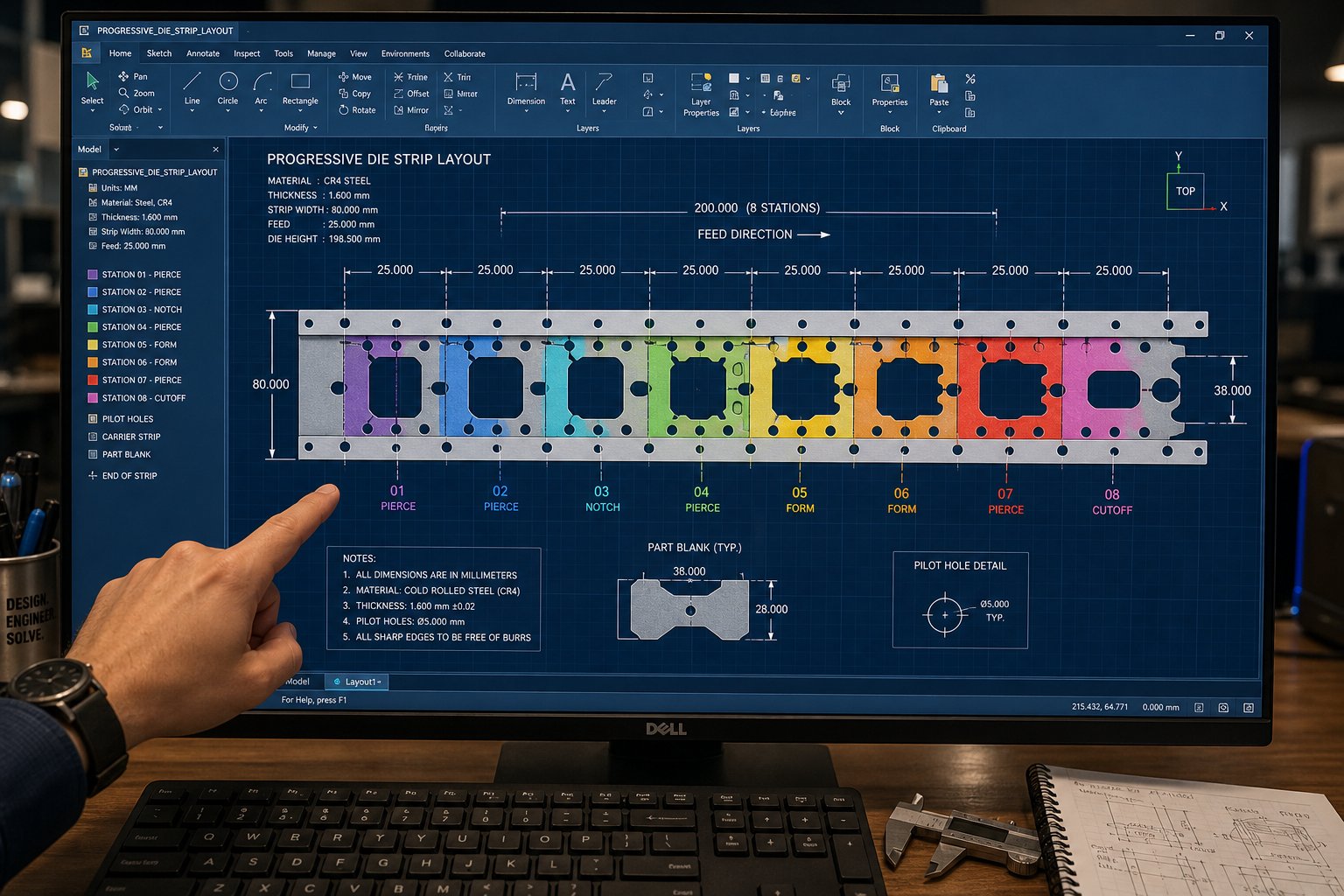
Every progressive die starts as a strip layout. Before a single block of tool steel gets machined, before guide pins are specified or die shoes are ordered, an engineer sits down with the part geometry and asks a deceptively simple question: how do I arrange these operations on a strip of metal so that the result is accurate, efficient, and buildable? That planning stage is where progressive die design either succeeds or quietly sets up problems that won't surface until tryout, or worse, during production.
Strip layout is the DNA of a progressive stamping tool. It defines the progression pitch, the station count, the carrier configuration, and ultimately the material utilization that drives your per-part cost. Yet most RFQs treat it as a supplier's internal concern rather than a specification worth discussing. If you understand the logic behind these decisions, you can evaluate die proposals more critically and identify where a design might be under-optimized.
Strip Layout Planning and Material Utilization
When engineers begin a progressive stamping die design, the first decisions revolve around four interdependent variables: strip width, pitch distance, number of stations, and carrier strip configuration. Each one affects the others, and the goal is to find the combination that maximizes material yield while maintaining strip integrity throughout the forming sequence.
Strip width is determined by the part's maximum cross-section dimension perpendicular to the feed direction, plus the material needed for carrier strips on one or both sides, plus the bridge material between the part edge and the strip edge. A common rule of thumb sets the minimum bridge thickness at 1.25 to 1.5 times the material thickness, though larger parts or high-speed applications may require wider bridges for stability.
Pitch distance, the amount the strip advances per stroke, equals the part's maximum dimension in the feed direction plus the bridge between consecutive parts. This measurement stays constant throughout the run and must account for any material that forming operations will pull from the carrier. Get it wrong, and you either waste material with excessive spacing or create interference between adjacent stations.
Station count depends on part complexity. A simple flat washer might need three stations: pierce, blank, done. A complex automotive bracket with multiple bends, embossments, and trimmed features could require fifteen or more. Each additional station adds die length, increases cost, and demands a longer press bed, but trying to combine too many operations into too few stations creates excessive forces, alignment challenges, and maintenance headaches.
Carrier strip configuration determines how the part stays connected to the strip as it moves through the die. There are two fundamental approaches:
- Solid carriers work well for parts that remain flat throughout processing. The strip edge itself acts as the transport framework, providing maximum rigidity and feed stability.
- Stretch web carriers incorporate strategic cuts or loops that allow the carrier to flex vertically. These are essential for parts requiring deep draws or complex forms that pull material downward, because the carrier must accommodate that vertical movement without distorting the pitch.
The choice between single-row and multi-row layouts is another early decision that significantly affects economics. A single-row layout places one part across the strip width. It's simpler to design, easier to maintain, and produces more predictable scrap patterns. Multi-row layouts arrange two or more parts across the width, which improves material utilization for smaller components but adds die complexity and can create unbalanced cutting forces.
When is multi-row worthwhile? Imagine a small connector terminal that measures 8mm wide. Running it single-row on a strip produces significant edge scrap on both sides. Nesting two or three rows across the strip, potentially mirrored or offset, captures material that would otherwise go straight to the scrap bin. For high-volume electronics or automotive connectors running into the hundreds of millions, even a few percentage points of material savings translates into substantial cost reduction over the program life.
Nesting and part orientation decisions interact directly with grain direction requirements. If the part has critical bends that must run perpendicular to the rolling direction, that constrains how the blank can be oriented on the strip. Sometimes the optimal orientation for material yield conflicts with the orientation needed for formability, and the engineer must make a trade-off. In practice, a well-designed metal stamping die design targets at least 75% material utilization, meaning no more than 25% of the incoming strip becomes scrap. Achieving higher yields requires creative nesting, tight bridging, and sometimes accepting a more complex die construction.
Operation Sequencing Across Stations
Arranging operations in the correct order is where progressive die design moves from geometry problem to engineering discipline. The sequencing logic follows principles rooted in material behavior, force management, and practical toolability.
The most fundamental rule: piercing comes before forming. You always want to create holes and slots while the material is still flat and firmly clamped against the die surface. Once a form is introduced, the strip gains three-dimensional geometry that makes subsequent flat cutting operations difficult or impossible without special accommodation. Pilot holes are pierced at the very first station so that every subsequent station benefits from precise registration.
Forming operations follow a different logic. Severe forms go early in the sequence, when the material hasn't yet been work-hardened by prior operations. Progressive bends build incrementally, taking a 90-degree form through two or three partial-bend stations rather than attempting it in a single hit. Deep draws are distributed across multiple stations with intermediate idle stations between them to allow the carrier to stabilize.
Idle stations, often puzzling to people reviewing a strip layout for the first time, serve several critical purposes. They provide physical space between adjacent operations so that forming punches don't interfere with each other. They allow stress relaxation in the strip between severe forming stages. And they give engineers room to add stations later if tryout reveals that an operation needs to be split into two gentler steps. Experienced progressive tool & die designers often include one or two idle stations as insurance during the initial layout, knowing that removing an unneeded station during tryout is far cheaper than adding one after the die is built.
Pilot placement strategy follows a predictable pattern: pilots are positioned in the carrier strip at every station or every other station, depending on accuracy requirements and strip stability. Placing pilots too far apart allows cumulative feed error to build up between registration points. Placing them at every station adds cost and complexity. For precision work where tolerances are tight, every-station piloting is standard practice. For looser-tolerance parts, alternating pilots may be sufficient.
Progressive die design software has transformed how engineers validate these sequencing decisions before committing to steel. Platforms like Logopress and AutoForm ProgSim allow designers to model the entire strip layout in 3D, simulate each forming operation incrementally, and predict issues like thinning, wrinkling, or springback before any tooling is machined. The simulation acts as a virtual tryout press, providing formability results and automatic blank development that shorten the design cycle dramatically. Engineers can test dozens of layout variations, adjusting station count, forming severity, and carrier geometry until the simulation confirms a stable process.
This capability has fundamentally changed how progressive stamping die design projects are executed. Where the old approach relied heavily on experienced toolmakers iterating through physical tryouts, correcting problems by shimming and grinding, modern simulation catches most issues during the digital design phase. The result is fewer tryout iterations, shorter lead times, and more predictable project costs.
Here's a summary of the key design decisions engineers must evaluate when planning a new progressive die:
- Grain direction alignment relative to critical bends and forms to prevent cracking
- Forming severity analysis at each station to stay within material elongation limits
- Scrap management, including slug ejection paths, carrier skeleton disposal, and bridge geometry that prevents jamming
- Strip width and pitch optimization to maximize material utilization above 75%
- Carrier type selection (solid versus stretch web) based on forming depth requirements
- Pilot hole placement strategy balancing registration accuracy against die complexity
- Idle station allocation for stress relief, interference clearance, and future contingency
- Force balancing across stations to prevent lateral strip drift and uneven die loading
- Feed direction selection relative to part features and burr direction preferences
- Single-row versus multi-row nesting based on part size, volume, and die cost trade-offs
Each of these decisions feeds into the die's overall architecture, cost, and performance ceiling. When reviewing a supplier's strip layout proposal, you'll notice that experienced engineers make deliberate choices at every level rather than defaulting to the simplest arrangement. The layout that looks most elegant on paper often reflects thousands of small trade-offs made by someone who understands how each decision ripples through tryout, production speed, and long-term maintenance.
A well-planned strip layout defines what's theoretically possible. But theoretical capability only becomes reality when the die consistently holds tolerances, detects deviations in real time, and prevents defects before they propagate through a production run.
Tolerances, Precision, and Quality Control in Progressive Stamping
A strip layout might look perfect in simulation, and a die might be built to exacting standards, but none of that matters if you can't define, measure, and maintain dimensional accuracy once the press starts cycling at production speed. Tolerance specification is where many RFQs fall short. Vague callouts like "tight tolerances" or "precision required" give your die supplier nothing to design against. Precision die and stamping programs demand specific, achievable numbers tied to the operations and materials involved.
Here's the challenge: not all features on a progressive die stamping are created equal from a tolerance standpoint. A pierced hole and a formed flange on the same part can have dramatically different achievable accuracy, and specifying the same tolerance for both either over-constrains the easy features (adding cost) or under-constrains the difficult ones (inviting rejects). Understanding what drives tolerance capability lets you write specs that are both realistic and meaningful.
Achievable Tolerances and Precision Factors
The dimensional accuracy you can expect from progressive stamping dies depends on three primary variables: the type of operation, the material being stamped, and the overall part complexity.
Operation type is the biggest differentiator. Pierced features, holes, slots, and cutouts created by shearing, consistently achieve the tightest tolerances. Industry data from precision stamping operations shows that pierced features can be held to tolerances as tight as ±0.001 inches, with ±0.002 inches being common for standard production work. Same-plane piercing, where multiple holes are created in a single station hit, is exceptionally accurate because all features reference the same die plate with no cumulative positioning error.
Formed features tell a different story. Bends introduce springback, material thickness variation, and angular tolerance that collectively loosen achievable accuracy. A typical 90-degree bend holds about ±1 degree angularly. Dimensional accuracy measured from a bend to another feature depends on how far that feature is from the bend line: the farther away, the more angular variation amplifies into linear error. Features located on different planes, separated by a bend, may need tolerances of ±0.005 inches or more to remain realistic.
Drawn features are looser still. Deep drawing involves controlled metal flow, wall thinning, and springback that introduce variability beyond what cutting or simple bending creates. If your part includes a drawn cup or shell, expect to specify wider tolerances on depth and wall dimensions than on pierced features in the flat areas of the same part.
Material type adds another layer. Softer, more ductile materials like low-carbon steel and copper produce cleaner shear edges and more predictable forming behavior, generally enabling tighter tolerances. Harder materials or those with high work-hardening rates, like stainless steel and high-strength alloys, generate more springback and accelerate tool wear, both of which degrade consistency over long runs. As reference data indicates, piercing tolerance capability ranges from ±0.002 inches for mild steel and aluminum to ±0.003 inches for high-strength alloys, with stainless steel falling between at roughly ±0.0025 inches.
Burr height control is a tolerance specification many engineers overlook. Burrs are an inherent byproduct of die stamping, formed when the punch shears through the material and the slug breaks away. A general rule holds that burr height will measure up to 10% of material thickness under normal conditions. For a 0.030-inch-thick strip, that means up to 0.003 inches of burr is standard. If your application demands lower burr, say for electrical contacts where burr interferes with plating or mating surfaces, you'll need to specify that requirement explicitly so the supplier can optimize punch-to-die clearance (typically 8-10% of material thickness per side) and plan appropriate sharpening intervals.
Flatness specifications on stamped parts are influenced by both the incoming material condition and the operations performed on it. Coil-fed strip carries inherent coil set (lengthwise curvature) and crossbow (transverse curvature) that straighteners reduce but don't always eliminate. Blanking and piercing operations introduce internal stresses that can cause localized warping, particularly in thinner materials or when perforations are placed close to edges. If flatness is critical, your specification should define the measurement area and acceptable deviation, and your die designer may need to add a coining or flattening station specifically to achieve it.
Positional accuracy between features depends on whether those features are created in the same station or across multiple stations. Features pierced in a single hit share the same die plate tolerance, giving you the tightest possible positional relationship, typically ±0.002 inches or better. Features created in different stations rely on pilot registration accuracy to maintain their relative positions. If holes are located closer than 1.5 times the material thickness to each other, or if they span across a formed area, expect to loosen positional tolerances to account for the additional variables involved.
In-Process Quality Control Methods
Specifying tolerances on a print is only half the equation. The other half is maintaining those tolerances across a production run that might span millions of cycles. Progressive die stampings demand real-time quality control systems that detect deviation before it becomes a batch of scrap or, worse, a quality escape that reaches your customer.
Statistical Process Control (SPC) forms the foundation of ongoing quality monitoring. Operators sample parts at defined intervals, measuring critical dimensions and plotting them on control charts. The goal isn't just to confirm parts are within tolerance; it's to detect trends, shifts, and drift patterns before they cross specification limits. A punch that's gradually wearing will show a predictable trend on an SPC chart for hole diameter, giving maintenance teams advance warning to schedule sharpening before out-of-spec parts are produced.
In-die sensing technology takes quality control from periodic sampling to continuous monitoring. Force sensors embedded in the die measure the load at each station during every single stroke. Displacement sensors track punch travel and material deformation in real time. If a slug fails to eject, a sensor detects the resulting height change before the next stroke drives the punch into an obstruction. If strip material unexpectedly hardens or thickens, force sensors register the change immediately. These systems feed data to the press controller, which can stop the press within a single stroke cycle when readings fall outside programmed limits.
Automatic feed monitoring addresses one of the most damaging failure modes in progressive stamping: the misfeed. A misfeed occurs when the strip fails to advance the full pitch distance before the press cycles. The result is punches hitting unpierced material, pilots missing their holes, and catastrophic die damage. Modern detection uses multiple approaches. Spring-loaded pilots that retract and trigger a stop signal when they fail to find their corresponding hole. Feed cycle sensors that verify strip position at multiple points during the feed stroke, stopping the press well before the ram reaches bottom dead center. Buckle sensors that detect strip obstruction at the die entrance when feed rollers slip against a jammed strip.
Die protection systems integrate all of these sensing inputs into a comprehensive crash-prevention strategy. Tonnage monitors measure press load continuously and compare it against a baseline signature. A normal stroke produces a predictable force curve; any deviation, whether from a slug pull, a misfeed, or a broken punch, produces an abnormal signature that triggers an immediate stop. The key challenge is detection speed: at 400 SPM, the press completes a full cycle in 150 milliseconds. The sensing system must detect the anomaly and engage the brake before inertia carries the ram through the crash.
Common progressive stamping defects and their prevention methods include:
- Slug pulling - A cut slug sticks to the punch face and gets pulled back into the die, obstructing the next stroke. Prevention: vacuum slug retention in the die opening, properly designed slug relief in die inserts, controlled air blast to eject slugs, and micron sensors that detect height changes when the die closes.
- Misfeeds - The strip does not advance the full pitch distance between strokes. Prevention: spring-loaded pilot detection, feed cycle sensors positioned at 50-70% of feed travel to enable early stopping, buckle sensors at the die entrance, and tight feed roller calibration.
- Short feeds - The strip advances partially but not to full pitch, leaving features misregistered. Prevention: electronic feed length verification, pilot engagement confirmation at each station, and servo feed systems with closed-loop position feedback.
- Die crashes - The press cycles with an obstruction or misaligned strip in the die space. Prevention: tonnage monitoring with per-stroke signature analysis, in-die proximity sensors, automated shut-height verification, and proper operator lockout procedures during setup.
- Excessive burr - Burr height exceeds specification due to punch wear or clearance degradation. Prevention: SPC tracking of burr measurements at defined intervals, scheduled punch sharpening based on hit counts, and proper punch-to-die clearance maintenance during regrinding.
- Material wrinkling or cracking - Formed features develop wrinkles from excess material flow or cracks from insufficient ductility. Prevention: proper blank holder pressure, forming severity analysis during design, lubricant specification and monitoring, and material incoming inspection for mechanical properties.
First article inspection (FAI) protocols establish the baseline that all subsequent production is measured against. During initial die tryout and at the start of each production run, a defined quantity of parts, often the first five to ten pieces, undergoes comprehensive dimensional inspection. Every critical dimension is measured against the print using CMM, optical comparators, or gauge pin systems. These measurements become the reference point for SPC charting and verify that the die, press, and material combination is producing in-spec parts before the run accelerates to full speed.
Ongoing measurement strategies balance thoroughness with production efficiency. Not every dimension gets checked on every part. Instead, engineers identify critical-to-quality (CTQ) characteristics, the dimensions that directly affect function, fit, or safety, and prioritize those for frequent sampling. Less critical dimensions are verified at longer intervals or through periodic audit measurements. The sampling frequency typically starts high at the beginning of a run and decreases once the process demonstrates stability, with immediate increases any time a tool change, material lot change, or other process variable shifts.
Tolerance control and quality systems keep individual parts within spec. But the real value of precision die and stamping shows up at scale, when those consistent parts flow into high-volume production programs across industries where failure isn't an option. The applications that demand this level of precision, and the volumes that justify the investment in sophisticated tooling and monitoring, span some of manufacturing's most demanding sectors.
High-Volume Applications Across Key Industries
Consistent tolerances and robust quality systems matter most when the stakes are highest. Automotive components progressive stamping programs might produce 20 million identical connector terminals per year. Medical device progressive stamping runs demand traceability on every single piece. HVAC systems need complex formed brackets at volumes that make any other process uneconomical. These aren't theoretical scenarios. They're the everyday reality that makes progressive die stamping the default choice for high-volume precision parts across manufacturing's most demanding sectors.
Automotive and Electronics Applications
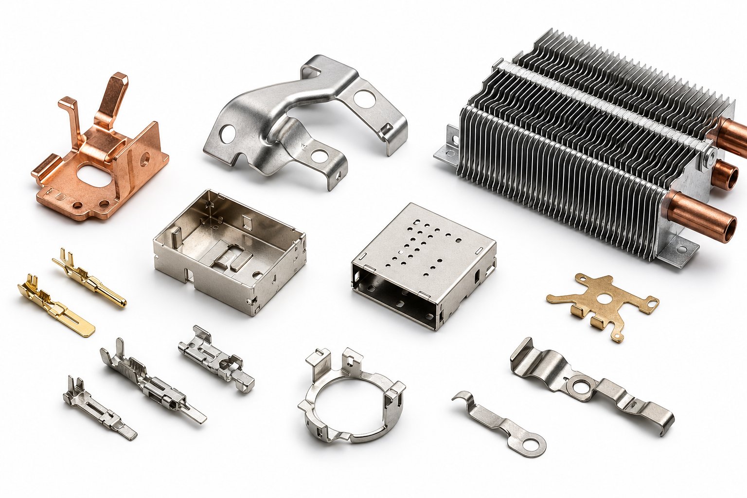
The automotive industry consumes more progressive stamped parts than any other sector. Connectors, terminals, brackets, sensor housings, relay components, and structural reinforcements all flow from progressive dies at rates that match vehicle assembly line speeds. A single vehicle can contain hundreds of stamped metal components, each one produced on automotive dies engineered to cycle millions of times without dimensional drift.
Why does automotive components progressive stamping dominate here? Volume and repeatability. An OEM progressive stamping program for a connector terminal might call for 50 million parts across a model lifecycle. At those quantities, the upfront investment in a precision automotive stamping die amortizes down to fractions of a cent per piece, and the process's inherent consistency eliminates the inspection burden that would cripple a less repeatable manufacturing method.
Electronics applications share the same high-volume logic but push miniaturization further. Connector pins, EMI/RFI shielding cans, lead frames, battery contacts, and switch components are stamped from strips as thin as 0.002 inches. As CEP Technologies notes, the growing demand for smaller and smaller devices drives the need for many types of very tiny metal parts across electrical and electronic applications. Progressive stamping handles this naturally because the strip remains registered by pilots throughout the entire forming sequence, maintaining positional accuracy even on features measured in tenths of a millimeter.
Medical and HVAC Industry Requirements
Medical progressive stamping introduces constraints beyond geometry and volume. Regulatory compliance under ISO 13485 demands full material traceability, documented process validation, and comprehensive lot-level records. Surgical instrument parts, implantable device components, and diagnostic equipment housings require not only tight tolerances but also verified cleanliness, burr-free edges, and materials with biocompatibility certifications. Every production run generates a documentation package nearly as complex as the parts themselves.
What makes progressive stamping viable for medical despite these overhead requirements? Once the process is validated, it reproduces identical parts with minimal variation, which simplifies the ongoing compliance burden. A validated progressive die running a qualified material lot produces statistically identical output, run after run. That consistency is exactly what regulatory frameworks reward.
HVAC progressive metal stamping occupies the opposite end of the complexity spectrum: large, aggressively formed brackets, heat exchanger fins, mounting plates, and ductwork components produced at volumes where cost per part must stay extremely low. Hvac progressive stamping programs often involve parts with deep draws, multiple bends, and lance-and-form features that would require three or four separate operations on a simpler press setup. Consolidating all of that into a single progressive die stroke cycle eliminates handling, reduces floor space, and drops per-part cost dramatically at scale.
Across all of these sectors, example part types demonstrate the breadth of progressive stamping's reach:
- Automotive - connector terminals, mounting brackets, sensor housings, fuel system clips, structural reinforcements, relay contacts, battery bus bars
- Electronics - EMI shields, lead frames, connector pins, battery contacts, switch springs, IC package leads
- Medical - surgical instrument components, implantable device housings, diagnostic probe contacts, drug delivery mechanism parts, catheter reinforcements
- HVAC - heat exchanger fins, blower motor brackets, damper linkage components, ductwork connectors, thermostat contacts
When evaluating suppliers for these demanding applications, production engineers should look for demonstrated capability in multi-station forming with tight repeatability and scalable mass production infrastructure. Suppliers like YICHEN support OEM progressive stamping programs across automotive, medical, and HVAC sectors with progressive stamping dies designed for exactly this profile: high station counts, precision registration, and die construction engineered for millions of cycles without degradation. The right die partner doesn't just build tooling; they understand the application-specific requirements that each industry brings to the table.
Industry fit determines whether progressive stamping is the right process. But fit alone doesn't close the business case. The economic framework behind tooling investment, volume thresholds, and per-part cost trajectories is what ultimately drives the build-versus-alternative decision for any production program.
Cost Structure and Economic Decision Points
Knowing that progressive stamping fits your industry and part geometry is only half the procurement equation. The other half is math. Specifically, understanding where progressive tooling becomes the most economical path compared to simpler alternatives, and where it doesn't. Too many RFQs skip this analysis entirely, defaulting to progressive dies because the part "looks like a stamping" without confirming that volume, complexity, and program life actually justify the investment.
The economics of dies and stamping are counterintuitive if you're used to fabrication pricing, where per-part cost stays relatively flat regardless of quantity. Progressive stamping flips that model: you pay heavily upfront for tooling, then enjoy per-part costs that drop asymptotically as volume climbs. Getting the crossover point wrong in either direction wastes money.
Tooling Investment Versus Per-Part Cost
A progressive die represents a concentrated capital investment. Industry tooling costs typically range from $30,000 to over $250,000 depending on station count, material type, tolerance requirements, and part complexity. Simpler geometries in mild steel land at the lower end. Multi-station dies with carbide inserts, tight tolerances, and complex forming sequences push toward the top.
Here's how amortization changes the picture. Imagine a die that costs $50,000. At 5,000 parts, that tooling adds $10.00 to each piece. At 50,000 parts, it drops to $1.00. At 500,000 parts, the tooling contribution falls to $0.10 per piece. The raw material and press time per part stay essentially constant regardless of volume, so your total piece cost converges toward that floor as quantities increase.
This relationship creates a clear decision framework: progressive stamping rewards volume. The higher your annual quantities and the longer your program life, the more aggressively that upfront investment amortizes into irrelevance. For long run progressive stamping programs spanning millions of parts over multiple years, tooling cost becomes a rounding error in the total program budget.
But what if your volumes don't reach that threshold? That's where alternative processes enter the conversation. A compound die stamping approach, for example, uses simpler tooling at lower upfront cost. It won't match progressive speed or handle multi-operation complexity, but for flat parts at moderate volumes, it can deliver lower total program cost precisely because the tooling investment is smaller.
Economic Crossover Points and Alternatives
Volume thresholds for progressive dies vary by source and application, but general industry guidance points to 50,000 to 100,000 units annually as the range where progressive tooling becomes clearly viable. Ultra-simple parts, think flat washers or basic clips, may justify the investment at 30,000 to 50,000 units. Complex parts with tight tolerances might need higher volumes before the per-part savings overcome the tooling premium.
Below those thresholds, simpler approaches often win on total cost. The table below compares progressive stamping and fabrication alternatives across the factors that drive your economic decision:
| Process | Tooling Cost Range | Ideal Volume Range | Part Complexity Capability | Per-Part Cost Trajectory |
|---|---|---|---|---|
| Progressive Die Stamping | High ($30K-$250K+) | 50,000+ units/year | High: multiple operations, 3D forms, tight tolerances across many features | Drops sharply with volume; lowest floor cost at scale |
| Compound Die Stamping | Low to Medium ($5K-$40K) | 5,000-50,000 units/year | Limited: single-plane operations (pierce and blank in one stroke) | Moderate and relatively flat; doesn't benefit as dramatically from volume |
| Transfer Die Stamping | High ($40K-$300K+) | 25,000+ units/year | Very High: large parts, deep draws, complex multi-stage forms | Drops with volume but slower cycle times keep floor higher than progressive |
| Multi-Slide / Fourslide Forming | Low to Medium ($3K-$25K) | 10,000-500,000 units/year | Moderate: best for wire forms, clips, and parts with bends from multiple directions | Low floor cost but limited to specific geometries; adding complexity raises price quickly |
A few patterns emerge from this comparison. Compound die stamping works well when your part is essentially flat with pierced features and a blanked perimeter, but no forming. It's a fraction of the tooling cost, and maintenance demands are lower, making it the sensible choice for simpler geometries at moderate volumes. Transfer die stamping handles parts that are too large or require draws too deep for a carrier strip to survive, but the mechanical transfer between stations slows cycle time and raises per-part cost compared to progressive at equivalent volumes.
Multi-slide machines occupy a niche for parts that need bends from multiple directions, clips, springs, and wire forms that would require awkward cam mechanisms in a progressive die. Their tooling is inexpensive and lead times are short, but they're geometrically constrained. If your part doesn't fit a multi-slide's capabilities, no amount of cost advantage matters.
One factor that often gets overlooked in the initial cost comparison is die lifespan. A well-built progressive die running high volume stamping programs in mild steel can last 10 million hits or more before requiring major refurbishment. In stainless steel or other abrasive materials, that number might drop to 2 to 5 million hits before critical components need replacement. Die life directly affects your long-term economics because it determines whether your tooling investment covers a single production contract or multiple program generations.
Consider a long run metal stamping program requiring 2 million parts per year over a five-year vehicle lifecycle. That's 10 million total hits. If your progressive die is engineered with carbide at critical stations and proper maintenance is followed, one die covers the entire program. If it's under-specified and reaches end-of-life at 3 million hits, you're either investing in a rebuild or ordering a replacement die mid-program, an unplanned expense that disrupts your cost model.
The takeaway for your RFQ: don't just compare quoted piece prices across suppliers. Ask about expected die life in total hits, the maintenance schedule assumed in the quote, and what happens when the die reaches its design limit. A supplier quoting a lower tooling price but building for shorter life may actually cost more over the full program when rebuilds and replacements enter the equation.
Economics dictate whether progressive stamping makes sense for your program. But even the strongest business case falls apart if the die can't sustain quality over its projected lifespan. The maintenance practices that extend tool life, and the supplier evaluation criteria that predict long-term production success, are where smart procurement teams separate capable partners from those who simply offer the lowest initial quote.
Die Maintenance and Sourcing for Scalable Production
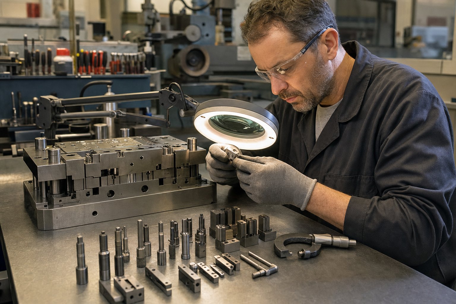
A progressive die that costs $150,000 and runs 10 million hits isn't a tool. It's a long-term production asset, and like any asset, its return depends entirely on how well it's maintained over its operational life. The difference between a die that delivers consistent parts at stroke 9,000,000 and one that starts drifting at stroke 500,000 comes down to disciplined stamping die maintenance practices executed on a predictable schedule.
Yet maintenance is precisely where many progressive die and stamping programs break down. Production pressure pushes maintenance windows shorter. Sharpening gets deferred "just one more run." Inspection checklists become afterthoughts. The result? Unplanned downtime, scrap spikes, and die repairs that cost multiples of what preventive maintenance would have.
Preventive Maintenance and Die Life Extension
True preventive maintenance is not die repair. As stamping industry expert Art Hedrick notes, unnecessary die repair stems from poor die design, setup procedures, and maintenance techniques. The goal is to address wear before it becomes failure, keeping the tool in production rather than in the repair shop.
Sharpening intervals are the most fundamental maintenance activity for any progressive die. Cutting sections and punch edges break down over time, producing burrs, feeding problems, and eventually safety issues. Rather than waiting for visible burr on parts, experienced shops track hit counts and schedule sharpening based on historical wear data for each specific die and material combination. A die running low-carbon steel might go 150,000 to 250,000 hits between sharpenings. The same die running stainless steel may need attention every 50,000 to 80,000 hits due to the abrasive chromium oxide layer accelerating edge breakdown.
When sharpening, the grinding process itself matters. Tool steel sections like D2 and M4 contain carbide pools that require appropriate grinding wheels, ones that break down freely rather than loading up and generating heat. Excessive heat during grinding causes softening, heat checking, or cracking of the die section. Flood coolant and proper wheel selection prevent thermal damage that would shorten the component's remaining life.
Inspection schedules should occur at every die pull, not just when problems appear. A systematic walk-through of the die catches loose fasteners, broken springs, galled surfaces, and worn components before they cascade into production failures. Keeping a detailed maintenance log that documents usage, repairs, and inspections allows teams to identify patterns and refine maintenance intervals over time.
Component replacement strategies follow a hierarchy. Consumable items like springs, pilots, and small punches are replaced on a schedule based on expected life cycles. Larger items like die inserts and forming sections are monitored through dimensional checks and replaced when measurements approach tolerance limits. The key insight is that individual components such as punches or inserts can be replaced independently, extending the overall die lifespan without requiring a full rebuild.
Die life measurement relies on cumulative hit counters installed on the press, tracked against maintenance events in a log or database. Every sharpening, component replacement, and adjustment gets recorded against the running hit total. This creates a predictive model: you'll know, based on historical data, that Station 4's piercing punches need sharpening every 120,000 hits and replacement every 600,000 hits. That predictability lets you schedule maintenance during planned downtime rather than reacting to failures during a production run.
The following preventive maintenance checklist covers the critical items that should be addressed at every scheduled die pull:
- Inspect all cutting edges for wear, chipping, or cracking and sharpen as needed using appropriate grinding wheels with flood coolant
- Check all screws for tightness and look for missing or backed-out dowel pins
- Inspect springs for breakage or fatigue and replace any that are near their expected life cycle end
- Examine all wear plates and cam surfaces for galling; regrind and refit as necessary
- Lubricate all mating die surfaces, guide pins, cam mechanisms, and moving components
- Clean all debris including slugs, slivers, and lubricant buildup from every station
- Verify pilot condition: check for tip wear, bending, or breakage and replace worn pilots
- Inspect stripper plate flatness and spring uniformity across the plate surface
- Confirm that all slug drop holes are clear and unobstructed through the entire die and bolster
- Check punch-to-die alignment at critical stations using test cuts on sample material
- Verify that die protection sensors are functioning and properly calibrated
- Inspect all safety guards and confirm they are secure and in proper position
- Dry the die thoroughly after cleaning to prevent rust, and apply protective coating if the die will be stored
- Record all maintenance actions, hit count, and observations in the die maintenance log
Proper maintenance doesn't just prevent failures. It extends tool life measurably. A well-maintained progressive die can last millions of cycles, providing consistent quality and reducing downtime throughout its operational life. The return on maintenance labor is enormous compared to the cost of emergency repairs, scrap parts, and unplanned production stoppages.
Evaluating Progressive Die Suppliers for Production Programs
Maintenance keeps your die running. But sourcing the right die in the first place determines your maintenance burden, your achievable quality ceiling, and your total program economics. When production engineers and procurement teams evaluate progressive die stampings suppliers for long-term production programs, the evaluation should extend well beyond quoted price and lead time.
Here's what separates a capable stamping die supplier from one that will create problems downstream:
Design capability and simulation resources. Does the progressive die manufacturer design dies in-house with dedicated engineering staff? Do they use forming simulation software to validate strip layouts before cutting steel? A supplier that relies entirely on experienced toolmakers without simulation backup is more likely to encounter issues during tryout that extend timelines and add cost. Look for evidence of 3D strip modeling, incremental forming analysis, and springback prediction in their design workflow.
Material and application expertise. Progressive die manufacturers who specialize in your material type and industry understand the specific challenges your program will face. A supplier experienced in stainless steel medical components knows how work-hardening affects station sequencing. One focused on automotive connector terminals understands the miniaturization and high-speed requirements that drive tool construction decisions. Ask about similar programs they've supported and what challenges they encountered.
First article inspection processes. How does the supplier validate the die before shipping it or starting production? A rigorous FAI process includes full dimensional inspection of sample parts against the print, capability studies (Cp/Cpk) on critical dimensions, and documented evidence that the die produces in-spec parts consistently. Suppliers offering progressive die stamping services should present FAI data as a standard deliverable, not an add-on.
Production ramp-up support. The transition from tryout to full-rate production is where many programs stumble. Does the supplier provide on-site support during initial production runs? Do they offer maintenance training for your internal team? Can they troubleshoot remotely using die sensor data? Progressive die metal stamping services that include ramp-up engineering support reduce the risk of extended startup periods that eat into your production schedule.
Maintenance documentation and die life projections. A good supplier delivers more than a die. They deliver a maintenance manual specific to that tool: recommended sharpening intervals by station, spring replacement schedules, critical wear points to monitor, and projected die life based on material and volume assumptions. This documentation is the foundation of your preventive maintenance program from day one.
Scalability and capacity alignment. If your program grows, can the supplier build duplicate dies or transition to multi-out configurations? If quality issues arise, do they have capacity to respond quickly with engineering changes? Teams sourcing progressive die stamping services for scalable production need partners whose capacity matches the program's trajectory, not just its launch volume.
For teams seeking a partner that addresses this end-to-end workflow, from die design and simulation through high-volume production, YICHEN's progressive stamping die solutions provide a reference point. Their approach covers efficient multi-station forming, tight repeatability, and the scalable mass production infrastructure that long-term programs demand. When your evaluation criteria include design-through-production support rather than just tooling delivery, suppliers with integrated capabilities reduce handoff risks and compress timelines from concept to full-rate output.
Ultimately, the quality of your progressive die and stamping program depends on getting three things right: specifying parts with enough detail that suppliers can design optimal tooling, selecting a progressive die manufacturer with the expertise to execute that design, and maintaining the resulting tool with the discipline that its engineering deserves. The RFQs that miss these elements produce dies that underperform. The ones that address them produce programs that run for years without surprises.
Frequently Asked Questions About Progressive Die & Stamping
1. What is a progressive die and how does it differ from a compound die?
A progressive die is a multi-station tool set housed within a single press that performs sequential operations on a continuous metal strip advancing one fixed pitch per stroke. Each station handles a distinct task such as piercing, forming, or blanking, with the finished part separating only at the final station. A compound die, by contrast, performs all cutting operations in a single stroke at one station, limiting it to flat, single-plane parts. Progressive dies handle far greater complexity including 3D forms, multiple bends, and tight multi-feature tolerances, making them ideal for high-volume programs exceeding 50,000 units annually where per-part cost must be minimized.
2. What tolerances can progressive die stamping achieve?
Achievable tolerances in progressive die stamping vary by operation type and material. Pierced features such as holes and slots consistently hold ±0.001 to ±0.002 inches because shearing produces clean, repeatable geometry. Formed features like bends typically hold ±1 degree angularly, with dimensional accuracy loosening as distance from the bend line increases. Drawn features require even wider tolerances due to springback and wall thinning. Material hardness also matters: mild steel and copper allow tighter tolerances than stainless steel or high-strength alloys. Specifying different tolerance bands for different feature types on the same part prevents over-constraining simple features while ensuring critical dimensions remain controlled.
3. How much does progressive die tooling cost and when is it worth the investment?
Progressive die tooling typically ranges from $30,000 to over $250,000 depending on station count, material type, tolerance requirements, and part complexity. The investment becomes economically justified when annual production volumes exceed approximately 50,000 to 100,000 units, because the high upfront cost amortizes rapidly across large quantities, driving per-part cost well below alternative processes. For long-run programs spanning millions of parts over multiple years, tooling cost becomes negligible per piece. Below those volume thresholds, simpler approaches like compound dies ($5K-$40K) or multi-slide forming ($3K-$25K) often deliver lower total program cost for geometries they can handle.
4. What materials work best for progressive die stamping?
Low-carbon steel (1008, 1010) offers excellent formability with high elongation, low tool wear, and the lowest raw material cost, making it the most common choice for brackets and structural parts. Stainless steel provides corrosion resistance but accelerates tool wear due to abrasive chromium oxides and work-hardens significantly during forming. Copper and brass excel in electrical applications where conductivity matters, with copper being softer and more conductive while brass offers better mechanical strength and more predictable stamping behavior. Aluminum works well for lightweight parts but requires coated tooling to combat galling. Material selection directly influences station count, press tonnage, sharpening intervals, and overall die design, so the choice should be driven by engineering trade-offs rather than cost alone.
5. How do you maintain a progressive die to maximize its lifespan?
Maximizing progressive die life requires scheduled preventive maintenance tied to hit counts rather than reactive repairs. Key practices include sharpening cutting edges at regular intervals (every 150,000-250,000 hits for mild steel, 50,000-80,000 for stainless), inspecting springs and pilots at every die pull, verifying punch-to-die alignment through test cuts, and tracking all maintenance actions in a detailed log. Proper grinding technique with flood coolant prevents thermal damage during sharpening. Component replacement follows a hierarchy: consumables like springs and small punches on schedule, larger inserts based on dimensional monitoring. A well-maintained progressive die can deliver 10 million or more hits in mild steel, while neglected tooling may fail after a fraction of that, leading to unplanned downtime and costly emergency repairs. Suppliers like YICHEN provide die-specific maintenance documentation covering recommended intervals and critical wear points from day one.


