


What Are Progressive Stamping Dies and Why They Matter
Imagine a single tool that punches, bends, forms, and cuts a finished metal part in one continuous motion, hundreds of times per minute. That is exactly what a progressive stamping die does. For production engineers and procurement teams tasked with scaling output while holding tight tolerances, understanding this tooling system from the inside out is the difference between a smooth launch and costly trial-and-error.
What Is a Progressive Stamping Die
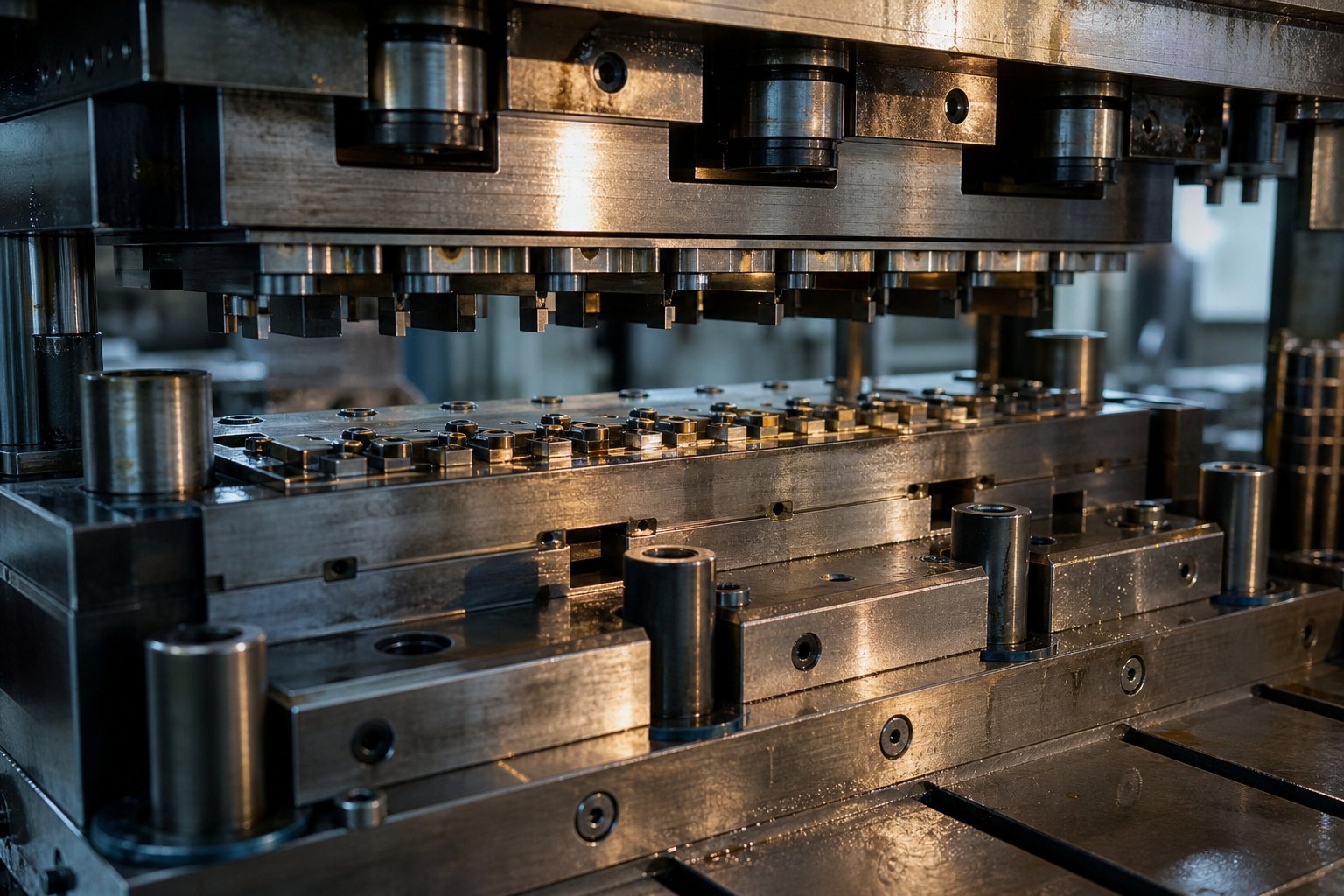
A progressive stamping die is a precision tool installed in a stamping press that moves a metal strip through a series of sequenced stations, each performing a specific cutting or forming operation per press stroke, until a finished part is separated at the final station.
So what is a progressive die in practical terms? It is a self-contained production system. A coil of sheet metal feeds into the press, and a servo feeder advances the strip by a fixed distance, called the pitch, with every stroke. At each station the strip encounters a different operation: piercing, bending, coining, embossing, or trimming. The part stays attached to a carrier strip throughout, maintaining alignment until the final cutoff releases it. One stroke in, one finished component out, continuously.
You will sometimes hear shop-floor teams call it a prog die. Regardless of the shorthand, the underlying principle is the same: multiple operations consolidated into a single automated cycle that eliminates part handling between steps.
Why Progressive Dies Dominate High-Volume Production
Progressive stamping delivers a combination that other methods struggle to match: speed, repeatability, and low per-unit cost at scale. Presses running progressive dies operate anywhere from 25 to over 200 strokes per minute, meaning a finished part drops every fraction of a second. Because each station is ground and hardened to micrometer-level precision, dimensional consistency holds across millions of cycles without manual intervention.
For procurement teams evaluating cost, the math is straightforward. Tooling investment is high upfront, but the marginal cost of each additional part shrinks to little more than raw material and press time. At annual volumes above 50,000 units, progressive dies routinely cut per-part costs by 30 to 80 percent compared to CNC fabrication methods. That economic logic is why automotive connectors, electronic shielding components, and HVAC brackets overwhelmingly come from progressive stamping operations.
The efficiency gains, however, depend entirely on what happens inside the die. Strip layout, station sequencing, and forming strategy determine whether a tool runs for millions of hits or demands constant intervention. That engineering depth is where this tooling type reveals its true complexity.
How the Progressive Die Stamping Process Works
Strip layout and station sequencing sound straightforward on paper, but in practice the progressive die stamping process is a tightly choreographed system where three machines act as one: the coil feeder, the press, and the die itself. Understanding how they interact at the stroke level reveals why this die process produces finished parts faster than any multi-step alternative.
Strip Feeding and Progression Mechanics
Everything starts at the uncoiler. A coil of flat sheet metal, typically ranging from 0.1 mm to 6 mm thick, unwinds into a straightener that removes coil-set curvature. From there, a servo or air feeder grips the strip and advances it a precise, repeatable distance with each press stroke. That distance is the pitch, and it corresponds exactly to the spacing between stations inside the die.
Accuracy here is critical. If the feed length drifts by even a fraction of a millimeter, every downstream station misaligns. That is why pilot pins, hardened cylindrical posts mounted in the upper die, enter pre-pierced holes in the strip at the start of each stroke. They physically pull the strip into exact registration before any cutting or forming begins. Think of pilots as the system's positional reset, correcting any minor feed variation every single cycle.
Station Sequencing From Blank to Finished Part
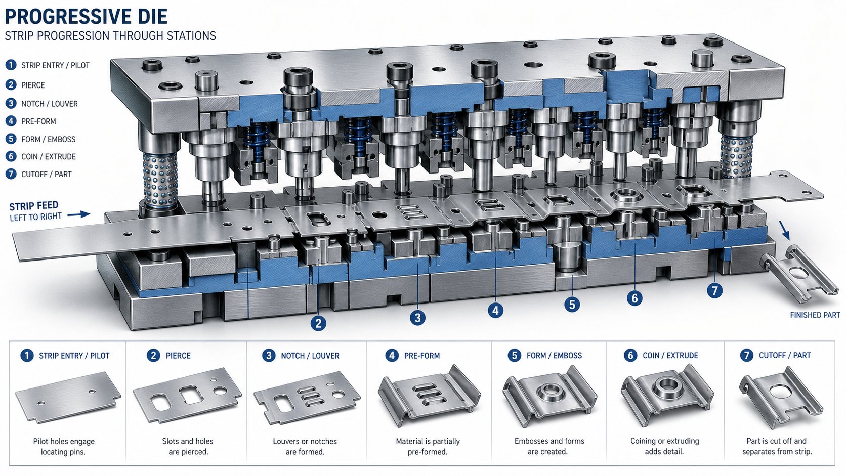
Inside the die, stations are arranged in a linear sequence. Each station performs one or two operations on the strip as the progressive stamping press closes. The part geometry develops incrementally, station by station, while remaining attached to the carrier strip via narrow tabs or webs of material.
A typical progressive stamping process follows this sequence:
- Pilot holes are pierced in the carrier strip to establish registration for all subsequent stations.
- Interior features such as slots, holes, and notches are pierced or blanked.
- Forming operations like bending, coining, or drawing shape the part geometry progressively.
- Additional trimming or restrike operations refine dimensions and relieve residual stress.
- The final cutoff station severs the finished part from the carrier strip, and it exits the die as a completed component.
Between stations, the partially formed part rides along on the carrier strip like passengers on a conveyor. This eliminates robotic pick-and-place handling and keeps cycle times measured in fractions of a second rather than seconds.
Press Stroke Cycle and Timing
How does a stamping press work in concert with the die? The press ram descends, closing the upper die onto the lower die and executing every station's operation simultaneously in one stroke. As the ram retracts, the feeder advances the strip one pitch length, and lifter pins raise the strip slightly off the lower die surface so it can travel freely. The ram descends again, and the cycle repeats.
A die stamping press running progressive tooling at 200 strokes per minute completes this entire sequence, feed, register, form, retract, in 300 milliseconds. At that speed, the feeder's timing window is measured in tens of milliseconds, and the die's stripper plate must clear the strip cleanly before the next advance. Every component in the system is synchronized to the press crankshaft rotation, making progressive die stamping less like a series of discrete events and more like a continuous mechanical rhythm.
That rhythm, however, only stays consistent when the individual components inside the die hold up under millions of repeated impacts. Punch geometry, die clearances, and material selection at the component level determine whether the tool sustains that cadence or starts producing scrap.
Critical Components Inside a Progressive Die
Punch geometry and die clearances keep the rhythm steady, but what exactly are those parts, and how do they fit together? A progressive stamping die is not a single monolithic block. It is an assembly of precision-ground stamping die components, each with a specific job, working in concert under extreme repetitive load. When you understand what each piece does, troubleshooting becomes logical rather than guesswork.
Upper Die Assembly Components
The upper half of the die mounts to the press ram and delivers the force that cuts and forms the strip. Its key elements include:
- Punch plate (retainer): A hardened steel plate that holds all tooling punches in precise position. Each punch is ground to match the geometry of the hole or form it produces, and the retainer locks them in place so they cannot rotate or shift under load.
- Backing plate: Positioned between the punch plate and the upper die shoe, this hardened plate prevents hardened inserts from being driven into the softer die shoe by the repeated impact force of the press.
- Stripper plate: This component clamps the strip material against the die block as the press closes. Equally important, it strips the material off the punches during the upstroke. Without it, the strip would cling to the metal punching tools on retraction, pulling up into the upper die and causing immediate damage.
- Pilots: Bullet-nosed pins that enter pre-pierced holes in the strip to settle it into final alignment before any operation fires. They correct minor feed inaccuracies every stroke.
Lower Die Assembly Components
The lower half sits on the press bolster and receives the cutting and forming forces from above. Its core elements include:
- Die block (die chase): The main body where cutting and forming contours are machined or inserted. In higher-volume steel stamping dies, the die block houses replaceable inserts made from premium tool steel or carbide, allowing localized repairs without rebuilding the entire block.
- Die buttons: Hardened cylindrical inserts pressed into the die block that provide the opposing cutting edge for each punch. The clearance between a punch nose and its mating button, typically 5 to 10 percent of material thickness, controls the quality of the cut edge.
- Stamping die lifters: Spring-loaded pins or rails that raise the strip slightly off the die surface after each stroke. This clearance lets the feeder advance the strip freely without dragging across cutting edges, reducing wear and preventing mis-feeds at high speed.
- Stop blocks: Precision-ground blocks that set the shut height of the die in the press. Technicians crush solder in a ground slot on the stop block to verify that punches and forms reach proper depth during setup.
Guidance and Registration Systems
Imagine closing the upper and lower halves together at 200 strokes per minute with clearances measured in thousandths of an inch. Guidance systems make that possible:
- Guide pins and bushings: Hardened pins mounted on one die shoe engage precision bushings on the other, aligning upper and lower halves to within tolerances of 0.0001 inch. Ball-bearing guide pins, which ride on caged bearings, have become industry standard for their smooth engagement and easy die separation.
- Die shoes (die set): The upper and lower foundation plates that hold every other component in position. They absorb deflection forces and provide a rigid mounting interface to the press.
- Die springs: High-force compression springs, either mechanical coil or nitrogen gas, that provide controlled pressure for stripping, holding, and part ejection functions throughout the stroke cycle.
The table below consolidates these stamping die components, their functions, and typical material selections into a quick-reference format:
| Component | Function | Typical Material |
|---|---|---|
| Die shoes | Foundation plates that mount all other components and maintain alignment | Mild steel or ductile iron |
| Guide pins and bushings | Align upper and lower die halves to within tenths of a thousandth | Hardened alloy steel; aluminum ball cages |
| Punch plate (retainer) | Holds and positions all tooling punches | A-2 or D-2 tool steel |
| Backing plate | Protects die shoe from punch impact forces | A-2 hardened tool steel |
| Stripper plate | Clamps strip material and strips it from punches on retraction | A-2 tool steel or mild steel (guided type) |
| Tooling punches | Cut, pierce, or form the strip material | D-2, M-2, CPM, or carbide |
| Die block / inserts | Provide opposing cutting edges and forming contours | D-2, M-2, CPM, or carbide inserts |
| Die buttons | Replaceable cutting-edge counterparts to punches | Through-hardened alloy steel or carbide |
| Pilots | Register the strip into precise position each stroke | Hardened tool steel, polished nose |
| Springs (mechanical / nitrogen) | Provide stripping force, hold-down pressure, and part ejection | Chrome-silicon wire or nitrogen gas cylinders |
| Lifters | Raise strip off die surface for free advancement between strokes | Hardened tool steel with spring return |
| Stop blocks | Set shut height and verify press depth during setup | Hardened tool steel, precision ground |
Every one of these parts must hold dimensional integrity across millions of press cycles. When a single punch wears beyond tolerance or a lifter spring fatigues, the entire system drifts. That interdependence is why material selection and design strategy at the component level carry as much weight as the overall strip layout, a relationship that becomes especially clear during the die design phase.
Progressive Die Design From Concept to Validation
Component interdependence at the physical level is one thing. Getting all those parts to work together before any steel is cut? That is where progressive die design either saves months of production headaches or creates them. A well-executed stamping die design begins not with CAD geometry but with a thorough understanding of what the finished part must do, how many are needed, and what constraints the material imposes.
Design Inputs and Customer Requirements
A typical metal stamping die design project starts when a customer sends a part print, usually accompanied by a 3D CAD model. But that drawing alone does not give the die designer enough to begin. Before any strip layout work happens, the designer needs to gather a full picture of the production context. Miss a critical input early, and the entire tool concept may need rework downstream.
Here are the critical design inputs required before progressive tooling development begins:
- Part geometry: 2D drawings and 3D solid models with complete GD&T callouts defining all critical dimensions and datum references.
- Material specification: Alloy type, temper, thickness, and mechanical properties including tensile strength, yield strength, elongation, and n-value.
- Annual volume requirements: Expected quantities per year, lot sizes, and projected program life, which directly influence die construction class and material choices.
- Tolerance requirements: Which features are critical-to-function (CTF) and which carry standard commercial tolerances, since tighter specs demand additional stations or coining operations.
- Secondary operations: Any post-stamping processes like plating, heat treating, welding, or assembly that impose constraints on burr direction, surface finish, or dimensional stability.
- Press and feeder availability: If the customer has an existing press line, its tonnage capacity, bed size, stroke length, and feeder type constrain the die envelope from the start.
As MetalForming Magazine notes, specifying sheet metal with too little technical detail can lead to die performance issues. A die designed around assumed material properties may produce scrap when actual production coils arrive with different hardness or elongation values. The die, in a sense, dictates what material it needs to run correctly.
Strip Layout Optimization Strategies
With inputs locked in, the designer moves to the single most consequential decision in progressive stamping die design: the strip layout. This is the blueprint that defines how the flat strip transforms into a finished part, station by station. It determines material utilization, die size, station count, force distribution, and ultimately per-part cost.
A strip layout specifies:
- Part orientation relative to the strip's feed direction and grain direction
- Pitch distance between stations
- Carrier type, width, and attachment points
- Operation sequence from first pierce to final cutoff
- Scrap skeleton geometry and material yield percentage
Sounds straightforward? In practice, every variable trades off against another. Rotating the part to align critical bends perpendicular to grain direction improves formability but may increase strip width and scrap. A shorter pitch reduces die length and press bed requirements but compresses stations together, limiting punch strength and maintenance access. Experienced designers often revise strip layouts several times during sample stamping trials, exposing feeding problems, force imbalances, and grain direction issues that only appear under actual press conditions.
Station count determination follows the strip layout. The designer sequences operations so that piercing and notching occur early while the material remains flat, preventing distortion of features during later forming. Bending and drawing stations come after the profile takes shape. Idle stations, where no operations occur, get inserted between heavy forming stations to manage force distribution and provide structural support in the die. A 12-station progressive stamping tool is not unusual for a moderately complex part, and intricate geometries can push counts past 20.
Simulation-Based Design Validation
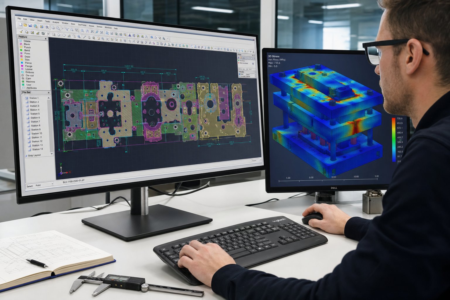
Before modern progressive die design software existed, toolmakers built the die, ran trial parts, identified problems, modified the tool, and repeated until results met spec. That cycle could consume weeks and tens of thousands of dollars in rework. Today, simulation has compressed that iterative loop into the digital space.
Finite element analysis (FEA) tools model material flow, thinning, wrinkling, and springback at each forming station before a single block of tool steel is machined. Engineers test multiple strip layout variations virtually, adjusting bend angles to compensate for springback or modifying draw depths to avoid thinning beyond acceptable limits. The result is a validated design that reaches production readiness faster with fewer physical prototypes.
Tonnage calculations are another area where simulation pays dividends. Each station's cutting and forming forces must sum to less than the selected press's capacity, factored for the working height above bottom dead center where mechanical advantage drops. For deep forming stations, working energy, not just peak tonnage, becomes the limiting factor. Simulation catches these constraints early, ensuring the progressive tooling matches the press line before commitments are made.
The combination of CAD/CAM parametric modeling, FEA forming simulation, and digital motion studies has reduced development timelines significantly. What once required three or four physical tryout iterations can often be resolved in one, cutting weeks off time-to-production and eliminating costly die modifications after hardening.
Yet even the most refined simulation model operates on idealized inputs. Real-world material variation, press deflection, and lubrication conditions introduce variables that only emerge at full production speed, which is why material selection for both the workpiece and the die components plays such a decisive role in long-term tool performance.
Materials in Progressive Stamping and Tool Steel Selection
Simulation models run on idealized material properties, but coils arriving at the press line carry real-world variation in hardness, elongation, and surface condition. Those differences ripple through every aspect of die performance. The progressive stamping materials you choose for the workpiece determine how many stations the die needs, how fast the press can cycle, and how long tooling components survive before maintenance.
Common Workpiece Materials and Their Stamping Characteristics
Progressive metal stamping handles a wide range of alloys, each bringing a distinct mix of formability, strength, and abrasiveness. A material with high elongation bends easily but may gall against tool surfaces. A harder alloy cuts cleanly but drives up tonnage demands and accelerates punch wear. Matching the workpiece to the application while accounting for die life trade-offs is a balancing act every engineer faces.
Here is how the most common progressive stamping materials compare:
| Workpiece Material | Formability Rating | Typical Applications | Die Wear Considerations |
|---|---|---|---|
| Carbon steel (CRS, SPCC) | Good to excellent | Brackets, housings, structural clips, automotive fasteners | Moderate wear; abrasive oxide scale on hot-rolled variants shortens punch life |
| Stainless steel (301, 304, 316) | Moderate | Medical enclosures, food-processing components, marine hardware | High galling tendency and work-hardening increase friction and accelerate adhesive wear |
| Aluminum (1100, 3003, 5052) | Excellent | Heat sinks, EV enclosures, lightweight structural parts | Soft material builds up on punch faces; requires polished tooling and frequent cleaning |
| Brass (C260, C270) | Excellent | Electrical terminals, decorative hardware, plumbing fittings | Low wear rate; zinc content provides natural lubricity, extending tool intervals |
| Copper (C110, C102) | Very good | Busbars, connectors, RF shielding | Mild abrasion but high ductility causes slug-pulling if clearances are too tight |
Carbon steel progressive stamping remains the workhorse for cost-sensitive, high-volume parts. Cold-rolled carbon steel offers a smooth surface, good formability, and low raw material cost, making it the default choice for brackets, clips, and structural components. Stainless steel progressive stamping demands more from the die: higher tonnage, tighter lubrication control, and tool steels rated for adhesive-wear resistance. Die designers often add idle stations when forming stainless grades to distribute forces and reduce stress risers in the strip.
Aluminum progressive stamping runs at higher press speeds because cutting forces are lower, but that softness causes material to adhere to punch surfaces, a condition called galling. Progressive stamping copper presents a similar challenge: the material's high ductility means slugs can be pulled back through the die if punch-to-die clearance is not optimized. Brass progressive stamping, by contrast, tends to be forgiving. The zinc content in brass acts as a mild lubricant, reducing friction at the tool interface and extending intervals between sharpening.
Tool Steel Selection for Die Components
The workpiece dictates what the die must endure. When stamping mild carbon steel at moderate speed, conventional tool steels like D2 (a high-chromium, high-carbon cold work steel) deliver acceptable life at reasonable cost. D2 provides a good balance of wear resistance and machinability, which is why it has been a standard for decades.
Harder or more abrasive workpieces change the equation. Stainless steel's work-hardening behavior can push cutting-edge hardness close to that of the die itself, accelerating chipping and fatigue cracking. In these cases, powder metallurgy (PM) tool steels offer finer, more evenly distributed carbides that improve both toughness and wear resistance compared to conventional ingot-cast grades. PM steels like CPM 10V or Vanadis 4 Extra resist abrasive wear without sacrificing the impact strength needed to survive high-speed blanking.
For steel progressive stamping at extreme volumes or with advanced high-strength sheet, carbide inserts become practical at the highest-wear stations, typically piercing and cutoff. Tungsten carbide offers hardness exceeding 90 HRA and can outlast conventional tool steel by five to ten times in abrasive applications. The trade-off is brittleness: carbide inserts require rigid die construction and cannot tolerate misalignment or off-center loading.
Surface treatments add another layer of protection. PVD coatings such as TiAlN or CrN reduce friction and resist galling, particularly when forming galvanized or stainless material. Ion nitriding hardens the substrate surface without dimensional distortion, creating a hard case that supports the coating above it. The combination of a nitrided substrate plus PVD coating has been shown to extend tool life from 50,000 parts to over 1.2 million parts in documented production scenarios.
Ultimately, tool steel selection is an economic decision layered on top of an engineering one. A carbide insert costs more upfront but slashes maintenance frequency and scrap rates over the life of the die. That total cost of ownership calculation, balancing tool material investment against downtime and replacement costs, becomes central once the die moves from the design bench to the production floor.
Progressive Dies vs Compound Dies vs Transfer Dies
Tool steel economics and total cost of ownership only tell part of the story. Before those decisions even come into play, a more fundamental question shapes the entire project: which type of die fits the part? Progressive dies are not always the answer. Depending on geometry, volume, and forming complexity, a compound die or transfer die may deliver better results at lower risk. Understanding the types of stamping dies and their selection criteria prevents costly mismatches between tooling investment and production reality.
Progressive Dies for Multi-Station Sequential Forming
Progressive die stamping excels when you need high volumes of small to medium-sized parts with moderate complexity. The strip stays connected throughout the process, maintaining positional accuracy across every station. That continuous registration is what makes this approach so repeatable at speed.
Where does die stamping with progressive tooling make the most sense? Picture automotive connector shells, bracket assemblies, or shielding components, parts that combine piercing, bending, and trimming in a single cycle. Annual volumes above 50,000 units typically justify the upfront tooling investment, and at quantities exceeding several hundred thousand, the per-part cost becomes difficult to beat with any other method.
The trade-off is flexibility. Because parts remain attached to the carrier strip, deep draws are limited by strip tension, and multi-directional forming becomes difficult. If a part requires rotation between stations or forming angles that the strip connection physically prevents, progressive dies hit a wall.
Compound Dies for Single-Station Simultaneous Operations
Compound die stamping takes a fundamentally different approach. Instead of sequencing operations across multiple stations, it completes all cutting operations in a single press stroke at one station. The punch and die work simultaneously from both sides of the material, producing the finished blank in one hit.
This makes compound dies ideal for flat parts that demand high dimensional accuracy, think washers, gaskets, shims, and simple blanked components. Because all features are cut in one stroke, there is no cumulative tolerance stack-up from station-to-station transfer. Flatness and concentricity tend to be superior to what a progressive die achieves on the same geometry.
The limitation? Compound dies cannot perform forming operations like bending or drawing. They handle cutting and coining, but any three-dimensional shaping requires a separate process. Production speed also falls below progressive tooling because parts typically require individual blank feeding rather than continuous strip progression. For medium volumes of simple flat parts where precision matters more than speed, compound dies deliver strong value at lower tooling cost.
Transfer Dies for Large or Complex Geometries
Transfer die stamping separates the workpiece from the strip early in the process. A mechanical transfer system, consisting of rails, fingers, or robotic arms, physically moves the free part from station to station. Each station operates on the part independently, without any strip constraint.
That freedom changes what is possible. Deep drawing, multi-directional forming, part rotation between stations, and operations requiring full access to the workpiece all become feasible. Transfer press tooling handles larger parts that simply cannot stay attached to a narrow carrier strip, components like automotive structural panels, deep-drawn housings, and complex formed enclosures.
As MetalForming Magazine notes, transfer dies eliminate the strip-progression constraint entirely, enabling more robust form and trim punches that improve die life and serviceability. Material utilization often improves as well, since blanks can be nested more efficiently than strip layouts allow. The trade-off is cycle speed and cost: transfer systems add mechanical complexity, synchronization requirements, and higher maintenance overhead compared to strip-fed progressive operations.
The table below puts all three types of stamping dies side by side across the decision criteria that matter most to production engineers and procurement teams evaluating stamping tool and die options:
| Selection Criteria | Progressive Die | Compound Die | Transfer Die |
|---|---|---|---|
| Ideal part size | Small to medium | Small to medium (flat only) | Medium to large |
| Annual volume threshold | 50,000+ units (cost-optimized above 200,000) | 5,000 to 100,000 units | 10,000+ units (justified by part complexity) |
| Typical tolerance range | +/-0.025 mm to +/-0.10 mm | +/-0.01 mm to +/-0.05 mm | +/-0.05 mm to +/-0.15 mm |
| Relative tooling cost | High (multi-station construction) | Low to moderate (single station) | High (die set plus transfer system) |
| Cycle speed | Very high (100-400+ SPM) | Moderate (60-150 SPM) | Moderate (15-80 SPM) |
| Forming capability | Pierce, bend, coin, shallow draw | Pierce, blank, coin (no forming) | Full range including deep draw and rotation |
| Best-use scenario | High-volume precision parts with multi-step features | Flat blanks needing tight dimensional control | Large or geometrically complex parts requiring unrestricted forming |
A practical selection rule emerges from this comparison. As volume increases, progressive dies become the economic winner. As part complexity increases, transfer die stamping gains the advantage. And when simplicity dominates the design, compound die stamping delivers precision at a fraction of the tooling investment.
The real-world decision is rarely black and white. Some stampers run hybrid approaches: a progressive die handles the initial blanking and piercing stages, then a transfer system moves the part through forming stations that require strip-free access. Dies and stamping processes can be combined creatively when the part demands it.
Regardless of which die and stamping method fits the application, one challenge remains constant across all three: maintaining part quality at production speed. The faster the press cycles, the less time operators have to catch drift, and the more critical automated monitoring becomes.
Quality Control and Monitoring in Progressive Stamping
A progressive die press running at 200 or more strokes per minute produces a finished part every 300 milliseconds. At that pace, a single undetected misfeed or worn punch can generate hundreds of defective parts in under a minute. Manual inspection simply cannot keep up. High speed progressive die stamping demands automated quality systems that detect process drift in real time, shut down the press before damage compounds, and provide data for continuous improvement.
In-Die Sensing and Real-Time Monitoring
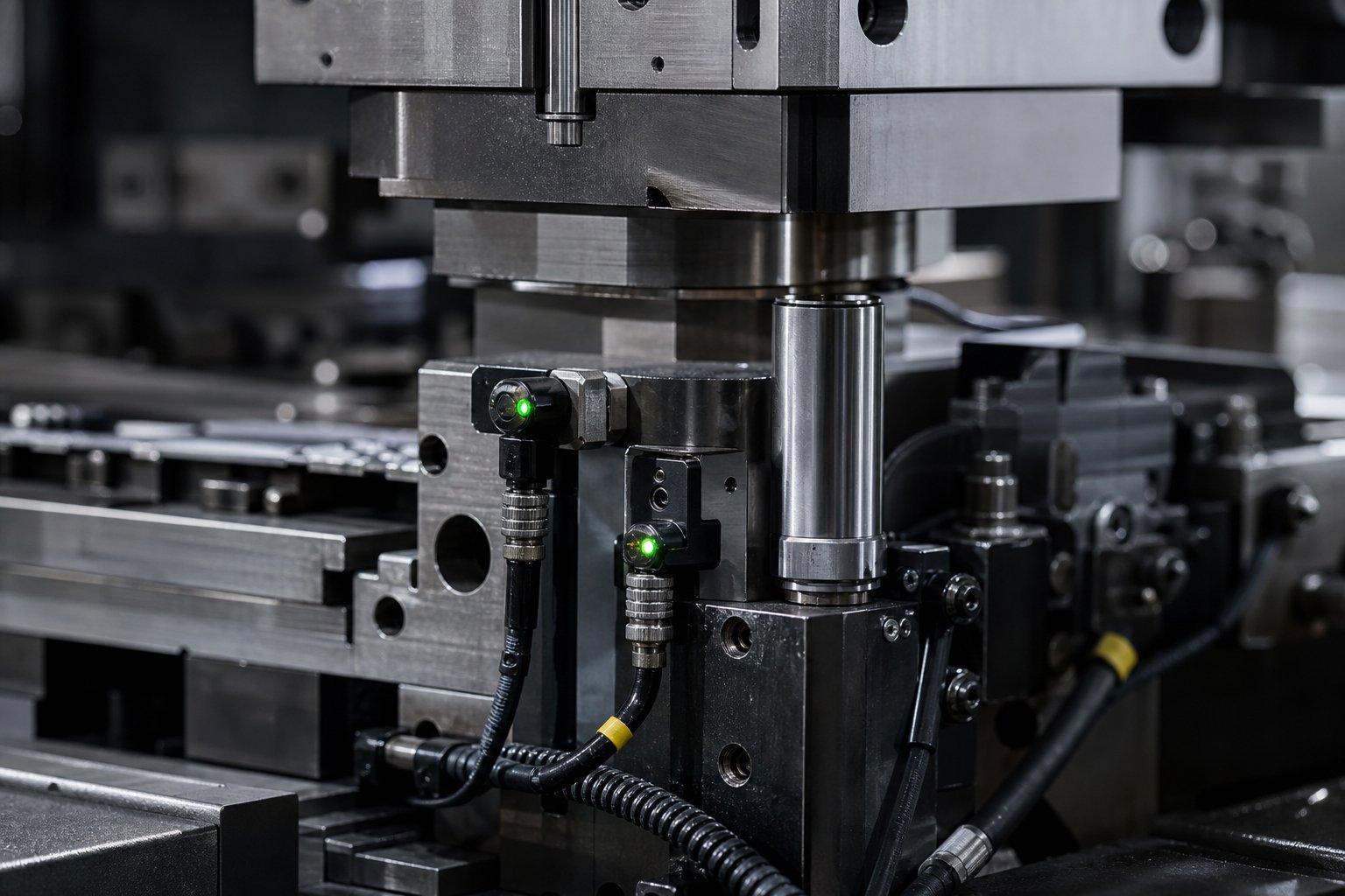
The most effective place to catch problems is inside the die itself, right where the action happens. In-die sensors monitor conditions at the point of contact between tooling and material, flagging abnormalities within a single stroke cycle. Modern die protection controllers use resolver-based timing signals accurate to one-third of a degree of crankshaft rotation, enabling detection of events lasting less than 10 milliseconds.
Common sensor types used in a progressive stamping machine and their functions include:
- Load sensors (strain gauge or die plugs): Measure stamping force at each station or across press columns. A sudden load spike signals a slug pull, double material, or die component fracture.
- Misfeed sensors (proximity or photoelectric): Verify that the stamping feed has advanced the strip the correct pitch distance before the press closes. If the strip is short or long, the controller stops the press before pilots attempt to re-register misaligned material.
- Part-out sensors (photoelectric or proximity): Confirm that finished parts and scrap slugs have fully ejected from the die. A part that sticks in front of the sensor indicates a jam that would cause a die crash on the next stroke.
- Slug sensors (proximity under die buttons): Detect pulled slugs that have been drawn back up through the die opening. Slugs trapped between the strip and punch face cause immediate tool damage.
- Stripper position sensors (eddy current probes): Monitor whether spring strippers return to their correct height. A sagging stripper indicates a broken spring or binding condition.
- Material buckle sensors: Detect strip buckling between the feeder and die entry, which indicates a feed problem or coil loop issue that will propagate into the die.
A well-implemented die protection program connects all die-mounted sensors through a single junction box and master cable rather than individual loose wires. This approach eliminates wiring errors during setup and prevents cable work-hardening failures caused by repeated coiling and uncoiling of loose sensor leads.
Statistical Process Control for Stamped Parts
Sensors catch acute failures, but what about gradual drift? That is where statistical process control steps in. SPC applied to progressive stamping uses load data as a continuous quality signal. Every stroke of the die stamping machine generates measurable force, and variations in that load correlate directly with dimensional changes in the stamped part.
Modern load monitors store force values for every hit in a production run, even at press speeds exceeding 1,000 strokes per minute. That data feeds X-bar and sigma control charts in real time. Upper and lower control limits are set at plus or minus three standard deviations from the sample mean, so the system stops the press only when the process genuinely moves out of statistical control rather than reacting to normal hit-to-hit variation.
Research published in the Journal of Manufacturing and Materials Processing confirms a strong non-linear correlation between stamping force and part geometry, particularly bending angles and overall width. This means load monitoring can serve as a proxy for dimensional measurement, catching quality drift before parts leave the press without requiring physical contact with the workpiece.
Dimensional Inspection Methods
In-die sensing and SPC handle real-time surveillance, but periodic dimensional verification remains essential to validate the monitoring system itself. Common inspection approaches for progressive stamped parts include coordinate measuring machines (CMMs) for GD&T verification, optical comparators for profile checks, and vision systems integrated into exit conveyors for 100-percent surface inspection at speed.
The interplay between these methods creates a layered quality system. In-die sensors provide instant crash prevention. SPC charts track process capability over the run. And dimensional inspection confirms that statistical signals correlate with actual part dimensions. Together, they let a progressive die press produce millions of conforming parts with minimal human intervention.
Catching drift early does more than protect part quality. It directly extends die life by preventing the cascading damage that occurs when a worn or broken component goes undetected for thousands of strokes. That connection between monitoring discipline and tooling longevity shapes the entire maintenance strategy for progressive dies.
Die Maintenance Practices and Total Cost of Ownership
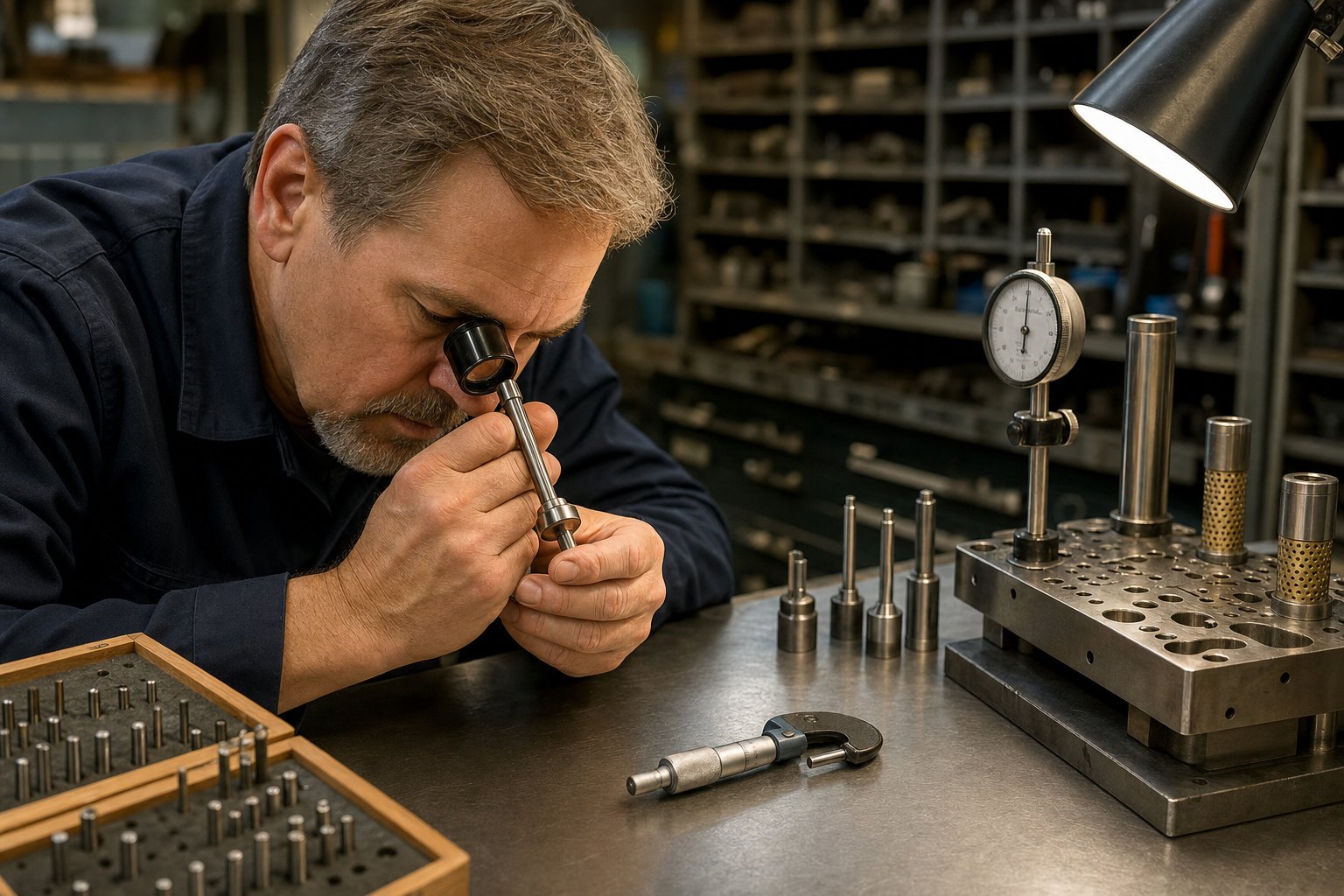
Catching process drift early protects both parts and tooling, but even the best monitoring system cannot eliminate wear entirely. Every press stroke removes microscopic material from cutting edges, compresses springs, and loads guide surfaces. Over hundreds of thousands of cycles, that cumulative degradation determines whether a stamping die set delivers predictable performance or spirals into unplanned downtime. Stamping die maintenance is not a reactive repair activity. It is a planned, measurable discipline that directly controls your cost per part over the life of the tool.
Preventive Maintenance Schedules and Inspection Points
A best-in-class maintenance program starts with one principle: identify, measure, and assess every area of the tool that will degrade over time. As The Fabricator notes, the most common oversight is assuming certain wear areas do not affect part quality, then being surprised when hit counts become inconsistent from run to run.
Effective preventive maintenance for progressive die tooling follows a documented schedule tied to stroke count rather than calendar time. The key checkpoints and wear indicators include:
- Cutting edge sharpness: Inspect all piercing and blanking punches under magnification. Measure burr height on sample parts at scheduled intervals. Burr growth beyond the specified limit triggers sharpening regardless of visual appearance.
- Pilot condition: Check diameter wear and nose profile. Worn pilots allow strip positioning drift that compounds across all downstream stations.
- Form punch and insert geometry: Measure forming surfaces against print tolerances. Even wear that seems cosmetic can shift bend angles or emboss depths out of spec.
- Lifter and spring function: Verify spring force with a load tester. Fatigued springs reduce strip lift height, causing drag marks and misfeed events at speed.
- Guide pin and bushing clearance: Measure lateral play between upper and lower die halves. Worn guides allow punch-to-die misalignment that accelerates edge chipping.
- Stripper plate flatness and parallelism: Check for uneven wear that creates inconsistent stripping pressure across the strip width.
- Scrap evacuation paths: Clear slug buildup and verify ejection channels are unobstructed. Trapped slugs cause immediate die damage.
Documentation is equally critical. Every service technician must follow the same inspection procedure, measure the same dimensions, and record results consistently. Without that standardization, you cannot apply SPC to your maintenance data or predict when the next service will be needed.
Regrinding Intervals and Component Replacement
Regrinding is the most frequent maintenance action on a progressive tool and die. Each sharpening cycle removes a controlled amount of material, typically 0.05 to 0.15 mm, from cutting punch faces and die button surfaces to restore clean shear edges. The interval depends heavily on workpiece material: high-speed stainless steel stamping may require regrinding every 50,000 to 100,000 hits, while softer brass or copper alloys can run 300,000 hits or more between services.
Waiting until burrs become visually obvious is a common mistake. By then, cutting loads have already increased, stripping forces have risen, and slug-pulling risk has escalated. Most precision stampers establish sharpening schedules based on actual stroke count and burr height measurement rather than operator judgment alone.
Each regrinding cycle shortens the punch. After a defined number of regrinds, the punch length falls below its minimum functional dimension and must be replaced. Progressive carbide stamping dies extend these replacement intervals significantly. Carbide inserts at high-wear piercing stations can outlast conventional D2 tool steel by five to ten times, which reduces both the frequency of sharpening and the total number of replacements over the die's production life.
Component replacement beyond punches includes springs, pilots, guide bushings, and lifter assemblies. A documented maintenance system tracks cycle counts for each consumable and schedules replacement before failure rather than after it. The goal is zero unplanned stops.
Factors That Determine Die Lifespan
How long should a progressive die last? The answer ranges from 200,000 hits on a poorly maintained tool to well over 10 million on one that receives disciplined service. The gap between those numbers comes down to a handful of controllable factors:
- Workpiece material hardness: Harder or more abrasive sheet materials accelerate edge wear and increase impact loads on every component. Advanced high-strength steels shorten service intervals compared to mild carbon steel.
- Lubrication strategy: Consistent, properly applied lubrication reduces friction, heat buildup, and galling. Localized dry contact zones, especially around deep piercing stations, cause accelerated wear even when the overall lubrication system appears functional.
- Press speed: Faster cycling generates more heat per unit time and increases dynamic forces on guides, strippers, and cutting edges. Higher speed demands more frequent inspection and often justifies premium tool steels or coatings.
- Strip guidance precision: Worn guide rails or degraded pilot systems allow lateral strip movement that side-loads punches, creating uneven wear and premature chipping.
- Die construction class: A Class A die built for long run progressive stamping uses hardened inserts, ball-bearing guides, and carbide at critical stations from the outset. A Class C prototype die uses softer materials and simpler construction, delivering lower initial cost but far fewer total hits before retirement.
When a die reaches the end of its economical service life, the decision becomes rebuild or replace. Rebuilding is justified when the die shoes and overall structure remain rigid, guide systems are recoverable, and only localized stations have worn beyond correction. A full rebuild can restore production capability at 40 to 60 percent of the cost of a new stamping die set. Replacement becomes the better investment when multiple stations have lost alignment, the die shoe has deflected permanently, or product design changes have made the existing strip layout obsolete.
Total cost of ownership for progressive die tooling is not the purchase price on the invoice. It is that initial investment plus every regrinding cycle, every replacement punch, every hour of unplanned downtime, and every scrapped part produced by a tool running outside spec. Suppliers like YICHEN address this lifecycle perspective by supporting the full span from die design through high-volume production and ongoing maintenance planning, helping teams control that total cost rather than optimizing only the upfront number.
Disciplined maintenance transforms the economics of long run progressive stamping. A die that receives consistent, documented service runs predictably, produces conforming parts, and reaches its full design life. That predictability is also what separates a well-managed die program from one that lurches between reactive repairs, and it becomes a key evaluation criterion when sourcing new tooling.
How to Source Progressive Stamping Dies for High-Volume Production
Predictable die performance depends on disciplined maintenance, but it starts even earlier, with choosing the right progressive die manufacturers to build the tool in the first place. A die sourcing decision shapes every downstream outcome: part quality, maintenance burden, production uptime, and total program cost. For production engineers and procurement teams evaluating progressive die stamping services, the challenge is distinguishing genuine engineering capability from polished sales decks.
Key Evaluation Criteria for Die Suppliers
Not every progressive stamping company can support the full scope of a high-volume program. Some specialize in prototype-class tooling. Others lack simulation resources or cannot service the die after delivery. The following criteria separate capable partners from those that will create problems downstream:
- Design engineering capacity: Can the supplier perform complete strip layout optimization, station sequencing, and tonnage analysis in-house? Outsourced design creates communication gaps and slows iteration.
- Simulation capabilities: Does the builder use FEA forming simulation and motion studies to validate designs before cutting steel? This directly reduces tryout iterations and time-to-production.
- Material range: Evaluate whether the supplier has documented experience with your specific alloy. A builder experienced in carbon steel may lack the tooling strategies needed for stainless or high-strength materials.
- Tolerance guarantees: Ask how the supplier validates dimensional conformance. Capable progressive die metal stamping services will reference Cpk targets and SPC data from production runs, not just print tolerances.
- Maintenance support: A die that runs for years needs a partner who supports regrinding, component replacement, and engineering changes over the full production lifecycle.
- Scalability: Can the supplier handle your projected volumes? OEM progressive stamping programs often scale from pilot quantities to millions of parts per year, and the die builder must design for that trajectory from day one.
As Eigen Engineering emphasizes, a supplier's track record with tooling longevity and after-sales responsiveness often matters more than quoted piece price. In-house trial and validation facilities are a strong indicator that the builder proves out tooling under realistic conditions before shipping.
Matching Die Capabilities to Production Requirements
Evaluation criteria provide a framework, but the real decision comes down to fit. A progressive die metal stamping partner must align with your specific production context: part complexity, annual volume, industry requirements, and quality documentation expectations.
Medical device progressive stamping, for example, demands traceability, validated processes, and documentation rigor that many general-purpose stampers cannot provide. Procurement teams sourcing for regulated environments should confirm that the supplier operates under ISO-certified quality systems and has direct experience supporting medical progressive stamping programs where lot control and audit readiness are baseline expectations.
For high-volume commercial and automotive applications, the priority shifts toward cycle speed, material utilization, and long-term cost stability. Suppliers like YICHEN support the full lifecycle from progressive die design through scalable mass production, offering production engineers a single-source partnership that covers multi-station tooling, tight repeatability requirements, and volume ramp without switching vendors mid-program.
Whichever progressive die stamping services you evaluate, request references from programs with similar volumes and complexity. Visit the facility if possible. Inspect their equipment, observe their quality workflows, and ask how they handle engineering changes after validation. The answers reveal whether a supplier will be a long-term asset or a short-term headache, and in high-volume progressive die metal stamping, that distinction compounds across every part the die produces.
Frequently Asked Questions About Progressive Stamping Dies
1. What is a progressive stamping die and how does it work?
A progressive stamping die is a precision tool installed in a stamping press that advances a metal strip through multiple sequenced stations in a single press stroke cycle. Each station performs a specific operation such as piercing, bending, coining, or trimming. The strip remains attached to a carrier throughout the process, and a finished part is separated at the final cutoff station. Servo feeders advance the strip by a fixed pitch distance each stroke, while pilot pins ensure exact registration before any operation fires. This allows production rates of 100 to 400+ strokes per minute with consistent dimensional accuracy across millions of cycles.
2. What is the difference between a progressive die and a transfer die?
Progressive dies keep the workpiece attached to a carrier strip throughout all stations, making them ideal for small to medium parts at very high speeds (100-400+ SPM). Transfer dies separate the blank from the strip early and use mechanical fingers or robotic arms to move the free part between stations. This gives transfer dies unrestricted forming capability including deep draws and part rotation, making them better suited for larger or geometrically complex parts. However, transfer dies cycle slower (15-80 SPM) and carry higher mechanical complexity. Progressive dies win on speed and per-part cost at volume, while transfer dies win on forming flexibility for complex geometries.
3. How long does a progressive stamping die last?
Die lifespan ranges from 200,000 hits on a poorly maintained tool to over 10 million hits on one that receives disciplined preventive maintenance. Key factors affecting longevity include workpiece material hardness, lubrication strategy, press speed, strip guidance precision, and die construction class. Class A dies built for long-run production use hardened inserts, ball-bearing guides, and carbide at critical stations. Regular regrinding at scheduled stroke-count intervals, timely component replacement, and proper lubrication all extend usable life significantly. Carbide inserts at high-wear stations can outlast conventional D2 tool steel by five to ten times.
4. What materials can be processed with progressive stamping dies?
Progressive dies handle a wide range of metals including carbon steel, stainless steel (301, 304, 316), aluminum (1100, 3003, 5052), brass (C260, C270), and copper (C110, C102). Each material presents unique challenges. Carbon steel offers good formability and low cost but hot-rolled variants carry abrasive oxide scale. Stainless steel work-hardens and galls against tool surfaces. Aluminum runs at higher speeds but tends to adhere to punch faces. Brass is forgiving due to natural zinc lubricity. Tool steel selection, surface coatings, and lubrication strategies are adjusted based on the specific workpiece material to optimize die life and part quality.
5. What should I look for when sourcing a progressive die supplier?
Evaluate suppliers across six core criteria: in-house design engineering capacity for strip layout optimization and tonnage analysis, FEA simulation capabilities to validate designs before cutting steel, documented experience with your specific alloy and material range, tolerance guarantees backed by Cpk targets and SPC data, ongoing maintenance support including regrinding and component replacement, and scalability to handle volume ramps from pilot quantities to millions of parts annually. Request references from programs with similar complexity, visit the facility to inspect equipment and quality workflows, and confirm they can support engineering changes after validation. Suppliers like YICHEN offer full-lifecycle partnerships from die design through high-volume production and maintenance planning.


