


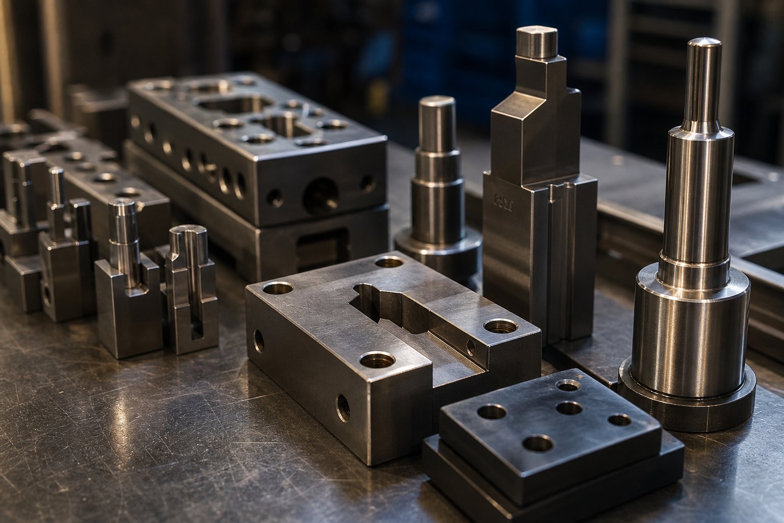
Why Die Material Selection Decides Stamping Success or Failure
Imagine standing over a cracked die block on a Tuesday morning. The press is down, parts are late, and operators are idle. The spec sheet promised 60 HRC hardness and long tool life. Yet here you are, staring at a fracture that turned a $15,000 tool into scrap. What went wrong? In most cases, the answer traces back to a single upstream decision: the wrong material for the job.
Metal stamping die materials are the steels, carbides, and engineered alloys used to build the punches, die blocks, and forming inserts that shape sheet metal under extreme pressure. Every time the press cycles, these materials absorb tonnage, resist friction, conduct heat, and maintain dimensional precision across thousands or millions of hits. The material you choose for a stamping die is not a line item on a purchase order. It is the single most influential variable in how long that die runs, how consistent your parts stay, and what each finished piece actually costs.
What Are Metal Stamping Die Materials
At a basic level, metal stamping die materials fall into four major families. Conventional tool steels like D2, A2, and S7 handle the bulk of general die work. High-speed steels such as M2 and M4 maintain hardness at elevated temperatures during fast-cycle operations. Powder metallurgy (PM) steels like CPM-10V and CPM-9V deliver uniform carbide structures that resist micro-chipping and extend tool life in demanding applications. And cemented carbides provide extreme wear resistance for ultra-high-volume or highly abrasive stamping conditions.
Each family sits at a different point on the hardness-toughness spectrum, and each carries distinct tradeoffs in machinability, cost, and thermal behavior. A metal stamping die built from the wrong category does not just wear faster. It can gall, chip, expand under heat, or fracture outright, turning a profitable production run into an expensive lesson.
Why Material Choice Drives Stamping Outcomes
Engineers, tool designers, and procurement teams often approach stamping dies as a cost decision. You compare quotes, pick a grade, and move on. But material selection echoes through the entire production lifecycle in ways that purchase price alone never captures. The steel in your die determines sharpening intervals, scrap rates, achievable tolerances, and how many times that tool can be reground before replacement. It determines whether your press runs three shifts uninterrupted or stops at 2:00 AM because a punch shattered mid-stroke.
Die material selection is not just a cost decision. It is a performance and maintenance decision that echoes through the entire production lifecycle, from first hit to final regrind.
This guide does not catalog every alloy on the market. Instead, it walks you through the decision logic that experienced toolmakers use when matching metal stamping materials to real production conditions. You will learn how workpiece hardness, production volume, die geometry, and failure modes each point toward specific material families, and how surface treatments and heat treatment parameters shift performance within those families. The goal is straightforward: equip you to make material choices that keep your stamping dies running and your cost-per-part predictable.
The starting point for any informed decision is understanding what separates one material category from another and where each one excels.
Major Die Material Categories and How They Compare
Every die of metal starts with a fundamental question: which material family fits the job? The answer depends on where you need to land on the hardness-toughness spectrum and how much wear the application dishes out. Below is a structured breakdown of the main categories you will encounter when specifying stamping tool material for any press operation.
Conventional Tool Steels for General Die Work
Conventional tool steels remain the backbone of most sheet metal stamping dies. They are well-understood, widely available, and heat-treatable to a broad range of hardness levels. The most common grades include:
- D2 (AISI D2 / cold-work, high-chromium): Features 11-13% chromium and 1.4-1.6% carbon, delivering high wear resistance with moderate toughness. Typical working hardness sits between 54-61 HRC. Commonly used for blanking dies, stamping dies, and trim tools where exceptional toughness is not the priority.
- A2 (AISI A2 / air-hardening): Contains roughly half the chromium of D2 (4.75-5.50%) and slightly less carbon. It balances wear resistance with better machinability and grindability, reaching 57-62 HRC. A solid choice for coining, trimming, and large blanking operations.
- S7 (AISI S7 / shock-resistant): The toughest of this group, with low carbon (0.45-0.55%) and modest chromium (3.0-3.5%). It works at 48-58 HRC and excels in applications involving impact, such as riveting dies, cold forming tools, and bending operations.
- O1 (AISI O1 / oil-hardening): An economical, easy-to-machine option for short-run and low-stress types of stamping dies. Lower alloy content means lower wear resistance, but also lower cost and simpler heat treatment.
These grades are typically through-hardened in vacuum furnaces to preserve clean surface profiles and minimize distortion.
High-Speed and Powder Metallurgy Steels
When conventional steels wear too quickly or chip under aggressive cycling, engineers step up to high-speed steels (HSS) and powder metallurgy (PM) grades. M2 and M4 high-speed steels retain hardness at elevated temperatures, making them suitable for high-stroke-rate metal die stamping where friction-generated heat softens lesser alloys.
PM steels take performance further. The CPM (Crucible Particle Metallurgy) process produces a homogeneous microstructure with fine, uniformly distributed carbides that conventional ingot metallurgy cannot achieve. Key grades include:
- CPM-10V (AISI A11): Contains roughly 9.5-10% vanadium, generating abundant hard vanadium carbides. Achieves 60-64 HRC with wear life often two to four times that of D2 in abrasive service while maintaining competitive toughness.
- CPM-M4: A PM high-speed steel combining high hardness with better toughness than CPM-10V. Well-suited for punches and intricate die sections that see both impact and wear.
- CPM-9V: Positioned between D2 and CPM-10V on the wear-toughness curve, offering a practical upgrade path when D2 falls short but maximum abrasion resistance is not required.
The PM advantage is cleanliness. Reduced carbide clustering and fewer non-metallic inclusions mean more predictable fracture behavior, which matters when you are building a die of metal with thin sections or tight tolerances.
Carbide and Ceramic Die Inserts
Cemented carbides, typically tungsten carbide in a cobalt binder (WC-Co), occupy the extreme wear-resistance end of the spectrum. They are brittle relative to steel, so they are used as inserts brazed or mechanically retained in steel die bodies rather than as monolithic tooling. Carbide inserts shine in ultra-high-volume progressive stamping where absolute edge life justifies the higher capital cost and specialized grinding requirements.
Ceramic inserts (silicon nitride, alumina-based) appear in niche high-temperature or non-magnetic stamping applications. Their use in general sheet metal stamping remains limited due to low fracture toughness and high tooling complexity.
| Material Family | Typical Hardness Range (HRC) | Relative Toughness | Relative Wear Resistance | Best-Fit Stamping Operations |
|---|---|---|---|---|
| Conventional Tool Steels (D2, A2, S7, O1) | 48-62 | Moderate to High | Moderate to High | General blanking, forming, trimming, short-to-medium runs |
| High-Speed Steels (M2, M4) | 60-65 | Moderate | High | High-speed progressive dies, elevated-temperature operations |
| PM Tool Steels (CPM-10V, CPM-M4, CPM-9V) | 58-64 | Moderate to Good | Very High | Abrasive workpieces, fine blanking, long-run precision dies |
| Cemented Carbides (WC-Co) | 74-92 (HRA scale) | Low | Extremely High | Ultra-high-volume inserts, abrasive materials, minimal-clearance dies |
| Ceramic Inserts | 70-80 (HRA equivalent) | Very Low | Very High | Specialty non-magnetic or high-temperature applications |
Notice how each step up in wear resistance generally costs you toughness and machinability. That tradeoff is the central tension in selecting stamping tool material, and it is where the properties behind these numbers start to matter more than the numbers themselves.
Critical Properties That Control Die Life and Part Quality
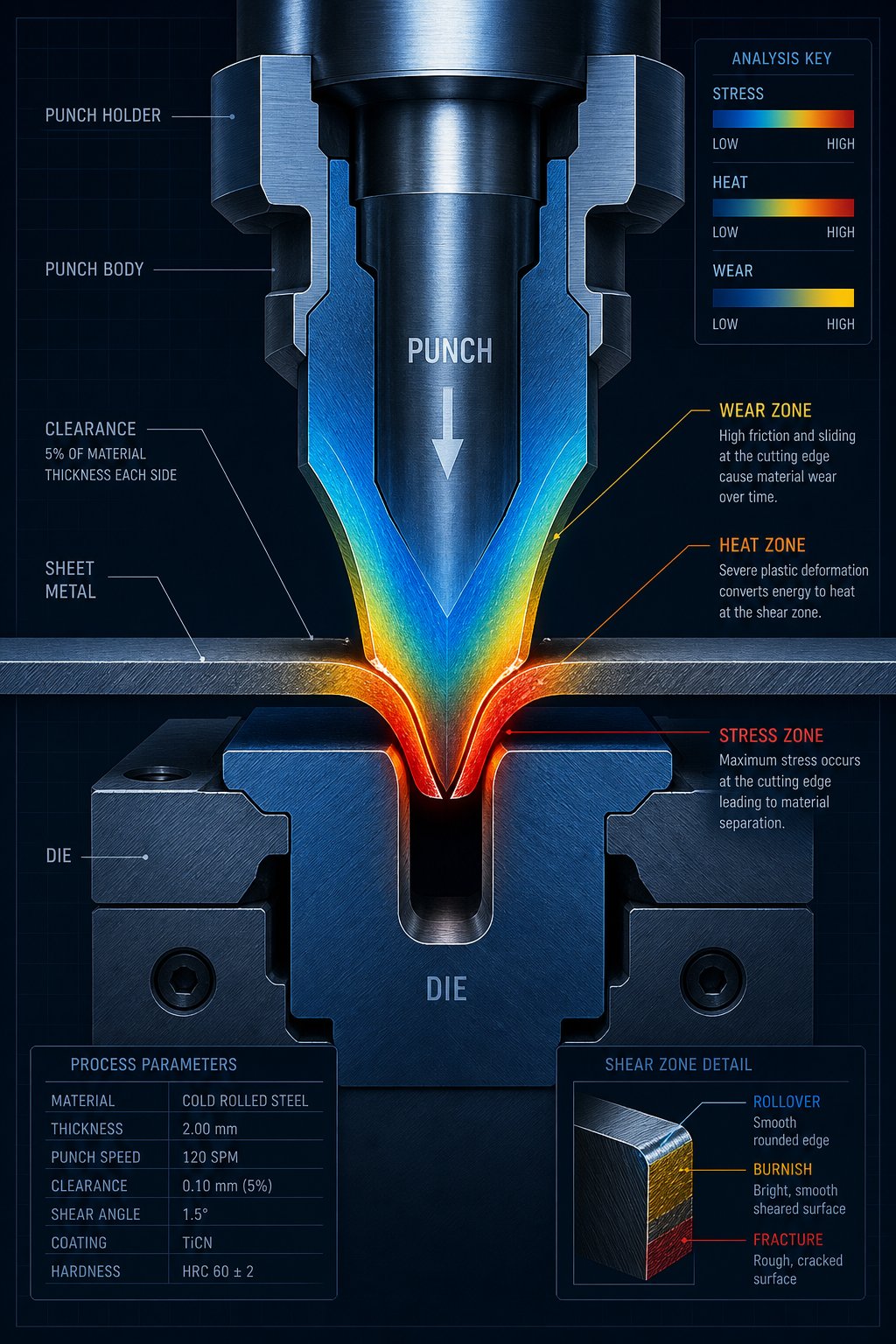
The comparison table in the previous section ranks material families by hardness, toughness, and wear resistance. But what do those terms actually mean when a punch hits sheet metal at 600 strokes per minute? Each property translates directly into a stamping outcome you can see, measure, and budget for. If you want to choose the right steel for stamping, you need to understand the five properties that govern whether your tooling thrives or fails.
- Hardness - Resists indentation and plastic deformation at the cutting edge. Higher hardness maintains sharper edges longer and preserves dimensional accuracy of stamped parts across extended runs.
- Toughness - Absorbs impact energy without fracturing. Insufficient toughness causes chipping and cracking on thin punches, small-diameter piercing tools, and any geometry where cross-sections are narrow relative to the applied load.
- Wear Resistance (Abrasive and Adhesive) - Resists material loss from contact with the workpiece. Abrasive wear erodes cutting edges and accelerates burr growth; adhesive wear (galling) occurs when workpiece material bonds to the die surface, increasing friction and degrading part finish.
- Compressive Strength - The maximum load the tool section can handle before permanent deformation. When compressive strength is insufficient, punch tips mushroom or die details crush under tonnage, producing oversized features and accelerated tool failure.
- Thermal Stability - The ability to retain hardness and dimensional accuracy as friction-generated heat builds during high-speed cycling. Hot stamping machine steel and high-speed dies demand thermal stability to prevent edge softening mid-run.
These five properties are not independent sliders you can crank up individually. Raising one almost always pulls another down. That tension is what makes die material selection an engineering decision rather than a catalog lookup.
Hardness vs. Toughness - The Fundamental Tradeoff
Picture two extremes. A glass cutting wheel is incredibly hard but shatters on impact. A rubber mallet absorbs shock all day yet cannot hold a cutting edge. Every metal for stamping dies lives somewhere between those poles. D2 at 61 HRC resists abrasion beautifully, but its high carbide volume makes it more prone to micro-chipping under shock loads than S7 at 56 HRC. Conversely, S7 handles impact forces well but wears significantly faster in abrasive blanking applications.
As Dayton Lamina's technical data shows, toughness tends to decrease as alloy content increases because greater carbide volumes introduce more potential crack initiation sites. The PM manufacturing process partially offsets this by distributing carbides uniformly and at smaller sizes, which is why a PM steel like CPM-M4 can deliver both high hardness (62 HRC) and better impact resistance than its conventionally produced equivalent.
For practical selection, the question is not which property matters more. It is which failure mode you cannot tolerate. If chipping shuts your press down, lean toward toughness. If burr growth forces frequent regrinds, prioritize wear resistance. The workpiece material and die geometry tell you which direction to lean, a topic the next section covers in depth.
How Heat Treatment Transforms Die Performance
Here is something that surprises engineers outside the tooling world: the same base steel can behave like two entirely different materials depending on how it is heat treated. A block of A2 tempered at 400°F will be harder and more wear-resistant but less tough than the same block tempered at 900°F. Heat treatment is not a finishing step. It is where you dial in the final balance of properties.
The core sequence involves austenitizing (heating to dissolve carbides into the steel matrix), quenching (rapid cooling to form hard martensite), and tempering (reheating to relieve internal stresses and adjust hardness). Each parameter matters:
- Austenitizing temperature: Higher temperatures dissolve more alloy into the matrix, increasing potential hardness but also increasing grain size, which reduces toughness. Lower austenitizing temperatures produce finer grains and superior toughness at a given hardness.
- Tempering cycles: Tool steels for stamping are typically tempered between 400°F and 1000°F, often in two or three cycles. Multiple tempers convert any retained austenite formed during quenching into tempered martensite, reducing the risk of dimensional instability and brittle spots during service.
- Cryogenic treatment: Cooling to between -150°F and -310°F after quenching drives additional austenite-to-martensite transformation. Research across steels including D2, M2, and A2 shows that cryogenic processing generally increases hardness by 1-2 HRC and can improve the overall hardness-to-toughness balance, though it may reduce absolute toughness in some low-temper scenarios due to the loss of ductile retained austenite.
The practical takeaway? Two shops can buy the same D2 bar stock, heat treat it differently, and get vastly different die life. One ends up with a tough, stable tool running 200,000 hits between regrinds. The other watches punches chip at 30,000 hits because the austenitizing temperature was too high or the temper was insufficient. Specifying die material without specifying heat treatment parameters is like choosing an engine without specifying the fuel grade.
Properties and heat treatment tell you what a material can do. The next critical variable is what it has to work against: the specific metal being stamped and the wear mechanisms that workpiece creates.
Matching Die Materials to the Metals You Stamp
A die does not wear in a vacuum. The workpiece on the other side of the clearance gap dictates which wear mechanism dominates, how fast edges degrade, and ultimately which die material survives the job. Workpiece hardness determines the load each punch stroke absorbs. Thickness amplifies tonnage demands and heat generation. Surface finish influences friction and adhesion tendencies. Ignore any of these variables, and you end up with a perfectly good tool steel failing in the wrong application.
The pairings below cover the workpiece metals most commonly run on progressive and transfer presses. Each pairing identifies the dominant wear mechanism so you can select a die material that directly counters it.
Die Materials for Stamping Stainless Steel
Stainless steel metal stamping is where most galling problems live. Austenitic grades like 304 and 316 work-harden rapidly during forming, and their high chromium and nickel content promotes adhesive bonding between the workpiece and die surface. The result is material transfer, scoring, and progressive surface buildup that ruins part finish long before the cutting edge actually wears out.
For metal stamping for stainless steel, conventional D2 often falls short. Its large chromium carbides can pull out under adhesive loads, creating initiation sites for further galling. DC53, a modified 8% chromium cold-work steel with superior toughness, handles stainless steel stampings more reliably because its finer carbide structure resists micro-chipping and supports PVD coatings like TiCN or AlCrN that reduce adhesion. High-volume stainless applications frequently justify PM steels such as CPM-9V or CPM-10V paired with surface treatments, or tungsten carbide inserts at stations where galling is most severe.
Ferritic stainless grades (409, 430) generate less adhesive wear than austenitic types but still demand higher-alloy tooling compared to mild steel. SKD11 with proper polishing and lubrication handles medium-volume ferritic runs effectively.
Die Materials for Aluminum and Copper Alloys
Aluminum creates a different headache. It is soft, so abrasive wear is minimal, but its tendency to cold-weld onto tool surfaces causes severe galling and material pickup. Stamped aluminum sheet metal operations need die surfaces that resist adhesion above all else. A2 or D2 at moderate hardness (58-60 HRC) with DLC or TiCN coatings is a common solution. The coating eliminates direct aluminum-to-steel contact, which is the root cause of buildup.
Brass metal stamping and copper metal stampings present a friendlier scenario. Brass is relatively non-abrasive and does not gall aggressively, making it one of the easiest workpiece families on tooling. Standard D2 or even O1 in short runs performs well for stamping brass, and stamped brass parts often come off tools with minimal edge degradation. Copper is slightly more adhesive than brass but still far less problematic than stainless or aluminum. Polished D2 with good lubrication handles most copper stamping volumes without issue.
Handling High-Strength Steel Workpieces
Advanced high-strength steels (AHSS) with tensile strengths above 590 MPa shift the dominant mechanism back to abrasive wear and plastic deformation. The hard phases in dual-phase and TRIP steels act like fine abrasives, grinding away die surfaces at rates that can be several times higher than mild steel. Contact pressures increase substantially, and stamping forces needed to form AHSS can exceed the compressive strength of lower-grade die steels.
For AHSS work, the minimum starting point is typically D2 or SKD11 at full hardness (60-62 HRC), but high-volume AHSS programs move quickly to PM steels like CPM-10V or carbide inserts at high-wear stations. Surface coatings become almost mandatory. TD (thermo-reactive diffusion) vanadium carbide treatment and CVD coatings provide the surface hardness needed to resist abrasive erosion without sacrificing substrate toughness.
| Workpiece Material | Recommended Die Material | Key Wear Mechanism | Notes |
|---|---|---|---|
| Mild / Low-Carbon Steel (SPCC, 1008-1020) | D2, A2, SKD11 | Moderate abrasive wear | Most forgiving workpiece; standard tool steels perform well at typical volumes |
| Austenitic Stainless Steel (304, 316) | DC53, CPM-9V, CPM-10V + PVD coating | Adhesive wear / galling | Polished surfaces and coatings critical; lubrication must include EP additives |
| Ferritic Stainless Steel (409, 430) | SKD11, DC53 | Moderate adhesive wear | Less aggressive than austenitic; coating recommended for longer runs |
| Aluminum Alloys (5052, 6061) | A2 or D2 + DLC or TiCN coating | Adhesive wear / material pickup | Coating prevents cold-welding; avoid rough die surfaces |
| Brass / Copper | D2, O1 (short run), A2 | Minimal wear | Non-abrasive and low galling tendency; easiest on tooling |
| AHSS / Dual-Phase Steel (DP590-DP1180) | CPM-10V, carbide inserts, D2 + TD or CVD coating | Severe abrasive wear, plastic deformation | High contact pressure demands premium materials and surface treatments |
This table gives you a starting framework, but volume and die complexity refine the answer further. A brass blanking die running 5,000 pieces needs a very different investment than one running 5 million. The next consideration is how production quantity shifts your material decision up or down the cost-performance ladder.
Selecting Die Materials by Production Volume and Complexity
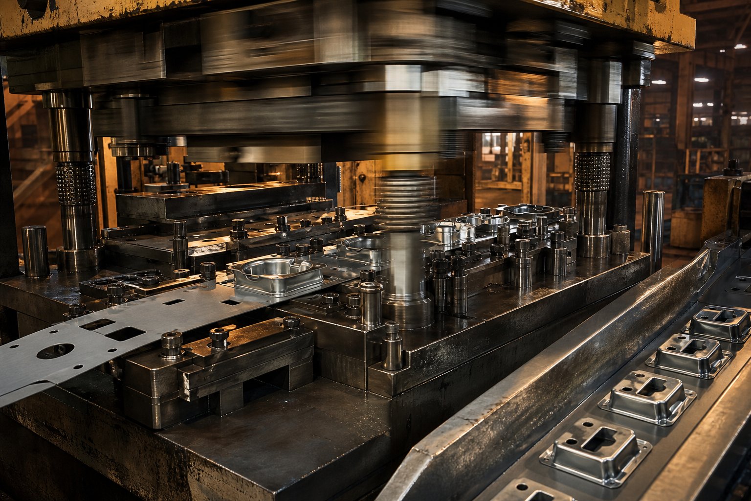
A brass blanking die running 5,000 parts and a carbon steel progressive stamping die running 5 million parts face completely different economic realities. The workpiece-to-material pairing tells you what kind of steel can survive the job. Volume tells you what kind of steel you can afford not to use. Underspecifying material on a high-volume program bleeds money through downtime and regrinds. Overspecifying on a short run locks up capital in tooling that never earns back the premium.
Production volume creates a natural tier structure that experienced tool designers use as their first filter before workpiece material or operation type even enters the conversation.
Short-Run and Prototype Die Material Choices
For prototype and short-run work under 10,000 hits, the priority shifts from wear life to machinability and lead time. You are not trying to survive a million cycles. You need a die built fast, adjusted easily, and affordable enough to justify a limited production quantity. O1 and A2 fit this space well. O1 machines cleanly, hardens predictably in oil, and costs significantly less per pound than PM steels. A2 offers a step up in wear resistance while remaining easy to grind and wire-EDM.
Consider a washer stamping operation producing 3,000 stamped washers for an equipment prototype. Spending on CPM-10V tooling makes no economic sense here. O1 at 58-60 HRC handles the soft, repetitive blanking geometry without issue and can be replaced or reworked cheaply if the design changes. The same logic applies to aluminum stamping dies used for prototype brackets or enclosures where volumes stay below a few thousand pieces.
Medium to High-Volume Material Escalation
Between 10,000 and 500,000 hits, the calculus shifts. D2 and DC53 become the workhorse grades for steel sheet stamping in this range. Their wear resistance carries you through multiple regrind cycles without needing premium alloys, and their cost-per-hit stays competitive against the expense of more exotic materials. Brass progressive stamping dies in this volume tier typically run D2 comfortably since brass is gentle on tooling, though stations with tight tolerances or thin forming punches may benefit from upgrading to A2 or CPM-M4 at those specific stations.
Above 500,000 hits, you cross into territory where PM steels and carbide inserts start paying for themselves. A progressive die producing stamped metal parts for refrigeration at volumes of 2 million annually cannot tolerate weekly regrinding cycles. CPM-10V or CPM-9V at wear-critical stations, combined with carbide inserts at piercing and blanking stations, keeps the press running and maintenance windows predictable. The higher material cost amortizes across enough parts to actually reduce your per-piece tooling expense.
Volume alone does not tell the full story, though. Die complexity acts as a multiplier. A simple single-station blanking die at 200,000 hits may run fine in D2. A 12-station progressive die at the same volume, with thin punch sections, close-tolerance pilots, and small piercing details, demands tougher or more wear-resistant material at those vulnerable stations regardless of total run length. Tight geometries concentrate stress, thin cross-sections amplify impact loads, and close clearances leave no room for edge deterioration.
Use this tiered decision path to narrow your material class before you finalize a specification:
- Estimate total production volume - Under 10K hits, 10K-500K hits, or 500K+ hits.
- Identify workpiece material - Soft and non-abrasive (brass, aluminum), moderate (mild steel, ferritic stainless), or aggressive (austenitic stainless, AHSS).
- Define the stamping operation type - Simple blanking, progressive with multiple stations, deep draw, or fine blanking.
- Assess die geometry complexity - Large cross-sections with generous radii, or thin punches, tight clearances, and intricate profiles.
- Select the recommended die material class - Short-run/simple geometry points to O1 or A2. Medium-run/moderate complexity points to D2 or DC53. High-volume/complex geometry points to PM steels or carbide inserts at critical stations.
This framework gives you a starting material class. The final selection within that class depends on how the die actually fails in service, which failure modes signal that your current material is under-performing, and what maintenance strategy makes economic sense across the tool's full life.
Common Die Failures and How Material Selection Prevents Them
A die does not simply stop working one day. It tells you it is struggling, sometimes for weeks, through subtle shifts in part quality, burr height, and surface finish. The challenge is reading those signals correctly and tracing them back to the material property that is falling short. Four failure modes account for the vast majority of premature die exits: chipping, cracking, adhesive wear (galling), and abrasive erosion. Each one points directly at a specific gap between what the stamping steel demands and what the die material delivers.
As MetalForming Magazine's failure analysis framework emphasizes, identifying the correct failure mode is the critical first step. Two dies can chip in the same location for entirely different reasons - one due to a material deficiency, the other due to a design flaw or service condition like chlorinated lubricant attacking a carbide binder. Accurate diagnosis prevents you from upgrading material when the real fix lies elsewhere.
Chipping and Cracking - When Toughness Falls Short
Chipping appears as small, irregular material loss along cutting edges or at punch tips. Cracking is the more dramatic version: a fracture propagating through a die section, sometimes catastrophically. Both signal that impact energy exceeded the material's ability to absorb it without breaking.
Thin punch cross-sections, small-diameter piercing tools, and tight inside corners concentrate stress far beyond what bulk hardness numbers suggest. When you run D2 at 62 HRC on a 2mm diameter piercing punch cycling through carbon steel metal stamping at high speed, you are asking a high-carbide, moderate-toughness steel to handle repeated shock loads on a minimal cross-section. The result is predictable: edge chipping within thousands of hits rather than hundreds of thousands.
The fix is straightforward in principle. Move toward a tougher material or a tougher heat treatment. S7 at 54-56 HRC absorbs impact without fracturing. CPM-M4 offers a middle path, delivering useful hardness (60-62 HRC) with better toughness than D2 thanks to its fine, uniformly distributed carbide structure. Alternatively, reducing austenitizing temperature during heat treatment refines grain size in the existing steel, improving fracture resistance without changing the grade.
Design details matter here too. Sharp corners, abrupt section changes, and inadequate fillet radii create stress risers that no material fully compensates for. If cracking recurs consistently at the same location despite a material upgrade, the geometry itself needs attention.
Galling and Erosion - Wear-Driven Failures
Galling shows up as material transfer from the workpiece onto the die surface. You will notice it first as scoring lines or shiny buildup on forming radii and draw surfaces. It is most aggressive in stainless stamping, where austenitic grades cold-weld to die surfaces under pressure, and in aluminum stamping, where soft workpiece material bonds to any microscopic roughness on the tool.
Abrasive erosion is the opposite mechanism. Instead of workpiece material sticking, it grinds. Hard phases in the workpiece - the martensite in dual-phase steels, oxide scale on hot-rolled stock, or silicon particles in certain aluminum alloys - act like fine sandpaper, progressively removing die material from cutting edges and forming surfaces. The visible result is dimensional drift: holes growing oversize, blanks expanding beyond tolerance, and burr height climbing steadily across a production run.
Galling demands surface hardness, low-friction coatings (TiCN, DLC, AlCrN), and polished die surfaces. The base die material must support those coatings without chipping beneath them. DC53 and PM steels serve as excellent substrates because their fine microstructure takes and retains a high polish. Abrasive erosion demands raw wear resistance: high-vanadium PM steels like CPM-10V, or carbide inserts where erosion is most concentrated. When you are running stamped copper at moderate volumes, neither mechanism is aggressive, so standard D2 with good lubrication handles both. But mix in stainless or AHSS workpieces, and the wear clock accelerates dramatically.
Regrinding Life and Maintenance Planning
Material selection does not just determine how long a die runs before it needs sharpening. It determines how many times you can resharpen before the tool section is spent, how easy each regrind cycle is, and how much productive press time you lose in the process.
Harder, more wear-resistant steels extend intervals between regrinds but require more grinding time and specialized wheel selection when they do come off the press. D2 regrinds reasonably well on conventional surface grinders. CPM-10V, with its dense vanadium carbide network, demands CBN or diamond wheels and slower feed rates. Carbide inserts often need dedicated EDM or diamond grinding setups. The tradeoff is that each regrind on a PM steel or carbide removes less material per cycle because the edges stay sharper longer, so total die life across all resharpening cycles often exceeds softer steels by a wide margin.
Predictive maintenance programs that track actual hit counts and part quality metrics outperform fixed-interval schedules. A PM schedule demanding regrind every 100,000 hits wastes tool life if the material and workpiece combination supports 150,000 hits. Conversely, running past the optimal regrind point accelerates damage exponentially - a slightly dull edge generates more heat and higher lateral forces, which chips or cracks the weakened edge, turning a simple regrind into a costly repair or replacement.
When should you replace rather than regrind? Consider replacement when:
- Chipping recurs within one regrind cycle - likely indicates insufficient toughness for the application, not a sharpness problem.
- Galling returns immediately after polishing - the base material or coating can no longer resist adhesive transfer; a material or coating upgrade is needed.
- Dimensional drift exceeds tolerance after fewer regrinds than expected - abrasive wear is consuming material faster than the steel can sustain; step up to a higher-alloy grade.
- Crack propagation is visible below the regrind surface - subsurface fatigue damage makes the section structurally compromised regardless of surface condition.
- Total material removed approaches the design limit for land length or punch height - further grinding alters die geometry and clearance relationships beyond specification.
Reading these patterns correctly saves you from the expensive habit of regrinding a die that actually needs a material change. Every failure symptom points toward a specific property gap. Chipping and cracking say the material lacks toughness. Galling says it lacks surface hardness or adhesion resistance. Erosion says it lacks abrasive wear resistance. Rapid regrind consumption says the die is fighting a workpiece it was never designed to handle.
Material selection addresses the root cause. But there is another lever that works on top of your base material choice - surface treatments and coatings that extend performance beyond what any uncoated steel can achieve on its own.
Surface Treatments and Coatings That Extend Die Life
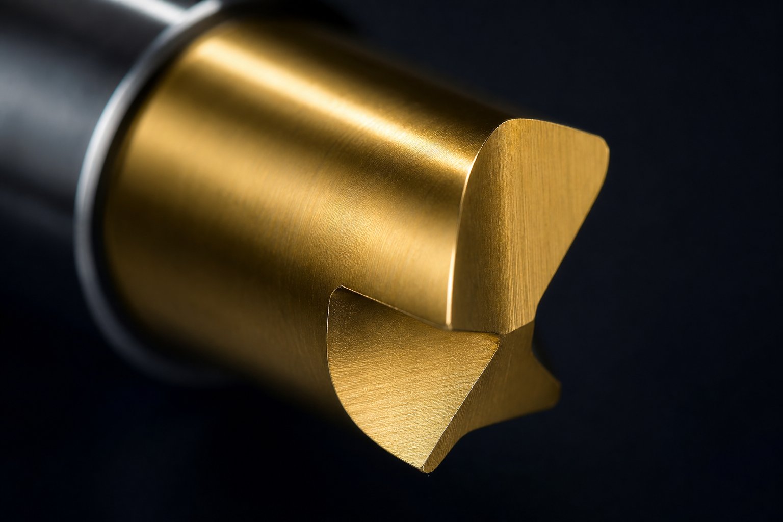
Even the best die steel has limits. A PM tool steel running stainless metal stamping will eventually gall if workpiece material contacts bare steel at high enough pressure and speed. A D2 punch blanking AHSS will erode regardless of hardness if nothing protects the cutting edge from abrasive wear. This is where surface treatments enter the picture - not as replacements for proper material selection, but as multipliers that push performance beyond what any uncoated substrate delivers alone.
The key principle: a coating is only as good as the foundation beneath it. A hard, brittle coating applied to a soft or improperly tempered substrate will crack and delaminate under stamping loads because the underlying material deforms plastically beneath the coating layer. That is why material selection and heat treatment must be resolved before coating decisions begin.
PVD and CVD Coatings for Stamping Dies
Physical vapor deposition (PVD) is the most widely used coating method for stamping tooling. The process runs at relatively low temperatures - generally below 900°F - which sits below the tempering range of most die steels. That means no loss of core hardness and minimal dimensional distortion, a critical advantage for closely toleranced punches and die inserts.
Common PVD compositions and their hardness values include:
- TiN (titanium nitride): ~2,400 HV. A general-purpose coating that reduces galling and material pickup. Effective for titanium stamping and moderate stainless applications.
- TiCN (titanium carbonitride): ~3,200 HV. Higher hardness than TiN with better abrasion resistance. Suitable for blanking and piercing operations on harder workpieces.
- AlCrN / AlTiN (aluminum chromium nitride / aluminum titanium nitride): ~3,400 HV. Excellent thermal stability for high temperature metal stamping and high-speed progressive dies where friction-generated heat is significant.
One case study from Richter Precision illustrates the progression clearly: a CPM-M4 compound punch producing custom bearing assemblies lasted 10,000 hits uncoated, 55,000 hits with CrN/CrC multilayer, 100,000 hits with AlTiN, and 250,000 hits when a dry-lubricant sulfide film was added on top of AlTiN. Same substrate, same workpiece - coatings alone delivered a 25x life improvement.
Chemical vapor deposition (CVD) operates at approximately 1,900°F, depositing TiC/TiN multilayer coatings through a gaseous chemical reaction. Because CVD is a gas-phase process, it uniformly coats complex geometries including deep recesses and blind holes. The metallurgical bond CVD produces is stronger than PVD's physical bond, offering superior adhesion under heavy forming loads. However, the high process temperature anneals steel substrates, requiring a full rehardening cycle afterward. This rehardening introduces dimensional risk, so CVD is best suited for cemented carbides and high-alloy D, M, and T steels that tolerate the thermal cycle. Steels like A2 and S7, which are sensitive to grain growth above their austenitizing temperatures, are poor CVD candidates when impact resistance matters.
TD Treatment and Nitriding for Extreme Wear Resistance
Thermal reactive diffusion (TRD) produces vanadium carbide layers directly on carbon-containing substrates through a high-temperature salt bath process. The resulting coating can reach hardness values up to 4,000 HV - harder than most PVD films. TRD coatings are particularly effective for tools stamping AHSS and other abrasive workpieces because the vanadium carbide layer resists erosion that would strip thinner PVD coatings over time.
TRD processing occurs in the 1,650–1,900°F range, similar to CVD. The advantage over CVD is that air-hardening steels like D2, A2, and S7 can achieve full hardness directly upon removal from the salt bath into air, sometimes eliminating the need for a separate posthardening step. This can provide better dimensional stability than CVD in certain tool geometries.
Nitriding takes a fundamentally different approach. Rather than depositing a surface layer, ion nitriding diffuses nitrogen into the die surface at around 950°F, forming hard nitride compounds with alloying elements like chromium already present in the steel. The result is a metallurgically bonded hardened case ranging from 0.0006 to 0.0035 inches deep, with surface hardness exceeding 58 HRC. Because the process temperature is low, distortion is minimal and the substrate retains its heat-treated properties.
Ion nitriding works exceptionally well as a base layer beneath PVD coatings. Research documented by the AHSS Application Guidelines showed that an ion-nitrided tool steel with a CrN PVD coating produced over 1.2 million parts, compared to just 50,000 parts for the same tool steel with conventional chrome plating. This layered approach - hardened substrate, nitrided case, then PVD top coat - addresses multiple failure modes simultaneously and is increasingly specified for high-volume stainless metal stamping and AHSS programs.
The interaction between substrate and coating also matters when working with less common workpiece metals. In niobium metal stamping, for example, the high work-hardening rate and moderate abrasiveness of niobium alloys demand a substrate with good toughness (to resist shock loads from the stiff workpiece) combined with a hard, low-friction coating to prevent adhesive pickup. PM steels with TiCN or AlCrN PVD coatings handle this combination effectively.
| Surface Treatment | Process Temperature | Coating Hardness | Best For (Failure Mode) | Substrate Requirements |
|---|---|---|---|---|
| PVD (TiN, TiCN, AlCrN) | ~750–900°F | 2,400–3,400 HV | Galling, adhesive wear, moderate abrasion | Any tool steel tempered above process temperature; minimum 58 HRC recommended |
| CVD (TiC/TiN multilayer) | ~1,900°F | 2,400–3,000 HV | Abrasive wear on complex geometries | Carbides, D/M/T steels; avoid A2/S7 under impact loads due to grain growth |
| TRD (Vanadium Carbide) | 1,650–1,900°F | Up to 4,000 HV | Severe abrasive erosion (AHSS, abrasive workpieces) | Carbon-containing steels (D2, A2, S7, M2); air-hardening grades preferred |
| Ion Nitriding | ~950°F | >58 HRC (case hardness) | Wear resistance base layer, fatigue resistance | Alloy steels with Cr, Mo, or V content; minimal distortion on pre-hardened tools |
| Nitriding + PVD (Duplex) | 950°F + 750–900°F | Case + 2,400–3,400 HV surface | Combined galling and abrasion on high-volume AHSS/stainless | Tool steels supporting both processes; D2, DC53, PM grades ideal |
Notice that every coating process has a temperature threshold your substrate must tolerate without losing hardness or dimensional stability. This is why coating selection cannot be separated from die material selection - they form a system, not independent choices. Specifying a PVD coating on a properly heat-treated PM steel is a deliberate engineering decision. Specifying the same coating on an under-tempered O1 punch is a recipe for delamination and wasted money.
Coatings extend die life, reduce maintenance frequency, and unlock performance tiers that base materials cannot reach alone. But the real question for engineers and procurement teams is not just whether a coating works - it is whether the combined investment in material, heat treatment, and surface treatment produces a lower cost per acceptable part over the tool's full lifecycle.
Total Cost of Ownership and When to Invest in Better Materials
A block of CPM-10V costs five to ten times more per pound than D2. Carbide inserts carry an even steeper premium. Procurement teams see those line items and instinctively push back. But the purchase price of die steel rarely accounts for more than 5-10% of total die build cost, and when distributed across millions of stamped steel parts, its contribution to unit cost becomes almost invisible. The question that actually matters is not what the steel costs on the loading dock. It is what each acceptable part costs when that steel is cycling in your press.
The cheapest die material is the one that produces the lowest cost per acceptable part - not the one with the lowest purchase price.
Calculating True Cost-Per-Hit
Cost-per-hit captures the total economic burden a die imposes across its full service life. It accounts for every dollar spent keeping that tool running and every dollar lost when it is not. Here are the factors that feed into the calculation:
- Die material and build cost - The upfront investment in steel, machining, heat treatment, and coatings.
- Hits between regrinds - How many cycles the tool runs before edge quality degrades beyond tolerance. Longer intervals mean fewer interruptions and more productive press hours.
- Number of regrinds possible - Total resharpening cycles before the die section must be replaced. PM steels and carbides often support more regrinds because each cycle removes less material.
- Downtime cost per regrind cycle - Press idle time, labor for die removal and reinstallation, and any expedited shipping if tools leave the facility for service.
- Scrap rate as the die wears - As edges dull or surfaces gall, reject rates climb. Each scrapped part carries the full cost of material and processing already invested in it.
- Secondary operations driven by die condition - Deburring, re-striking, or sorting that becomes necessary as tool wear progresses between maintenance windows.
Imagine a progressive die producing electrical stamping components - connector terminals stamped from phosphor bronze at 1,200 strokes per minute. A D2 die section lasts 80,000 hits before regrinding and supports 15 regrind cycles. A CPM-9V section in the same station lasts 200,000 hits and supports 20 cycles. The PM steel costs three times more upfront, but it delivers 4 million total hits versus 1.2 million for D2. Factor in six fewer annual die changes, lower scrap from sustained edge quality, and reduced deburring on finished metal stamping components, and the premium material cuts true cost-per-hit nearly in half.
When Premium Die Materials Pay for Themselves
The payback threshold depends on volume, workpiece aggressiveness, and how expensive downtime is on your specific press line. High-volume stamping metal parts in automotive or appliance production - think drawn metal housings cycling at 500,000+ annual volumes - almost always justifies PM steels or carbide inserts at wear-critical stations. The math simply works: more hits per maintenance event, fewer press stoppages per shift, and tighter dimensional control over longer runs mean lower cost per piece despite the higher tooling investment.
Where does upgrading become over-engineering? When the existing material already reaches end-of-program life without failure. If your D2 die produces 50,000 stainless steel stamping parts on a one-time order and retires with edge life to spare, spending three times more on PM steel bought you nothing. Similarly, short-run metal stamping products with annual volumes under 10,000 hits rarely generate enough cycles to amortize a premium material's cost advantage. The break-even point simply never arrives.
A practical rule: if your current die requires more than two unplanned maintenance events per production campaign, or if scrap rates climb above 1.5% before scheduled regrinding, the existing material is under-performing and an upgrade will likely pay for itself within the first full production year. Track actual hit counts, regrind frequency, and reject rates - these numbers tell you whether you are spending too little on material or just enough.
Cost-per-hit analysis gives you the financial logic. But translating that logic into a repeatable selection workflow - one that accounts for workpiece material, volume, geometry, and coatings in a single decision sequence - requires a structured framework that ties every variable together.
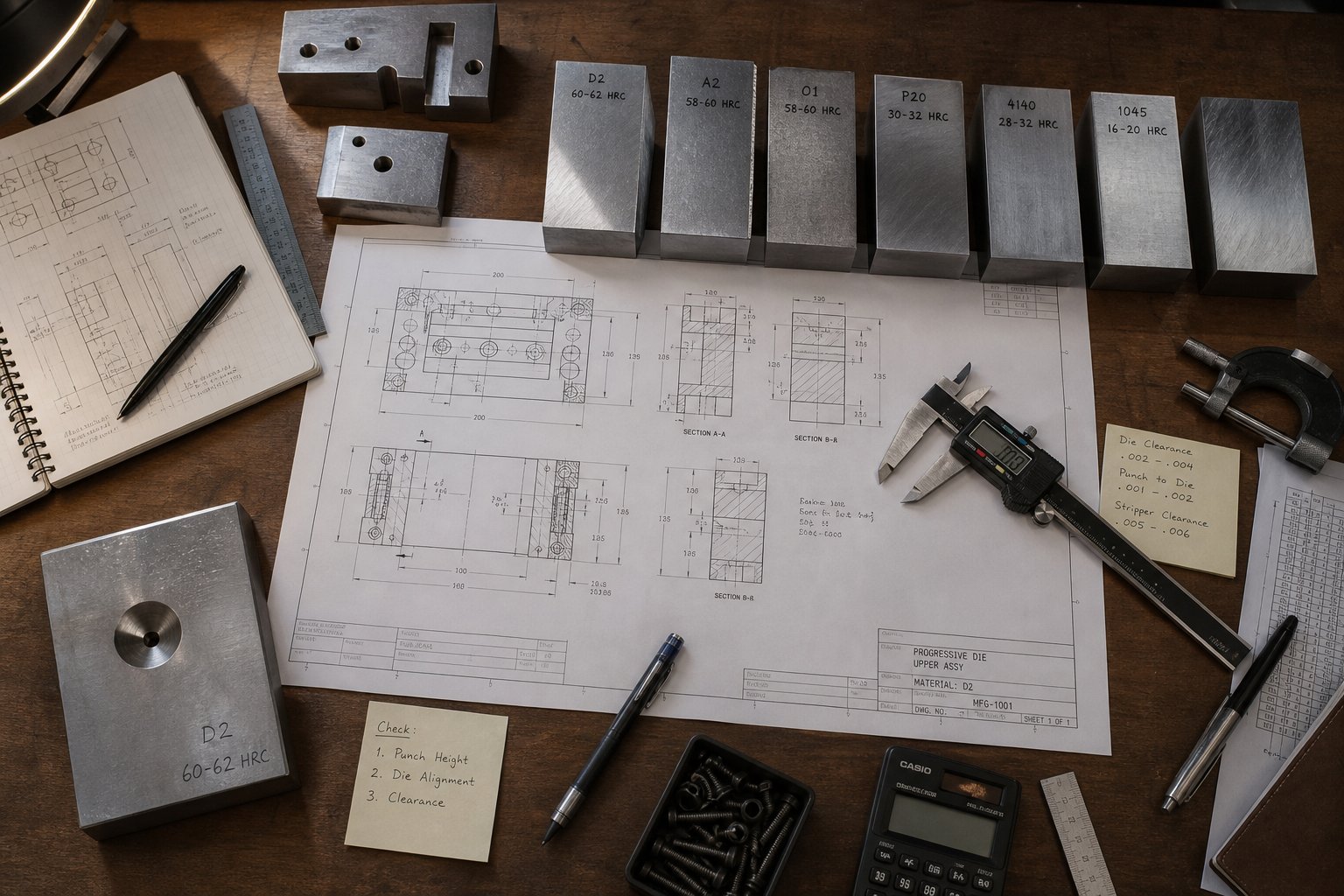
A Practical Decision Framework for Die Material Selection
Cost-per-hit analysis tells you whether an upgrade is justified. Workpiece pairing tells you which wear mechanism to counter. Volume tiers tell you how much tooling investment the program can absorb. But these are individual data points. Without a repeatable workflow that connects them in sequence, engineers end up making ad hoc decisions that work on one project and fail on the next.
The framework below consolidates everything covered in this guide into a linear decision path. It works for a single-station blanking die and for a 20-station progressive die producing precision metal stamping materials at automotive volumes. The steps are sequential because each answer narrows the options for the step that follows.
Step-by-Step Die Material Selection Workflow
- Identify the workpiece material and its properties. Hardness, tensile strength, thickness, surface condition, and tendency toward galling or abrasion define the threat profile your die must resist. This is step one because it determines the dominant wear mechanism before anything else matters.
- Define total production volume. Under 10K hits, 10K–500K hits, or 500K+ hits. Volume sets the economic ceiling for material investment and determines whether premium alloys can amortize their cost.
- Determine the stamping operation type. Blanking, piercing, forming, drawing, coining, and progressive die operations each impose different stress profiles. Deep draws demand toughness and surface finish. Fine blanking demands extreme hardness and tight clearances.
- Assess die geometry complexity. Thin punch sections, small piercing diameters, tight radii, and multi-station progressive layouts push material requirements upward regardless of volume. Complex geometry multiplies the toughness requirement.
- Select the die material class. Cross-reference the outputs from steps 1–4. Short-run plus soft workpiece equals O1 or A2. Medium-volume plus stainless workpiece equals DC53 or CPM-9V. High-volume plus AHSS equals CPM-10V or carbide inserts at critical stations.
- Specify heat treatment parameters. Define austenitizing temperature, quench medium, tempering cycles, and cryogenic treatment based on the balance of hardness and toughness the application demands. Two shops running the same steel with different heat treatments will get vastly different results.
- Select surface treatments and coatings. Match the coating to the failure mode identified in step 1. Galling requires TiCN or DLC. Abrasive erosion requires TRD or CVD. High-speed thermal loading requires AlCrN or AlTiN. Verify that substrate hardness and tempering temperature support the selected coating process.
This sequence is not one-and-done. Material selection is iterative. If a die fails in service, the failure mode tells you which step in the workflow produced an incorrect assumption. Chipping says step 4 or step 6 needs revisiting. Galling says step 7 needs a coating upgrade or step 1 underestimated the workpiece's adhesive tendency. Rapid erosion says step 5 underspecified the material class for the actual wear environment.
Workpiece Material Resources for Informed Decisions
Notice that the entire framework hinges on step one. If you mischaracterize the sheet metal for stamping - underestimate its hardness, overlook its galling tendency, or fail to account for work-hardening behavior - every downstream decision inherits that error. Accurate workpiece data is the foundation of sound die material selection.
For engineers evaluating metal for metal stamping across material families like aluminum, steel, stainless steel, brass, and magnesium, having a centralized reference for workpiece properties accelerates this first step considerably. YICHEN's Materials page serves as a practical starting point, consolidating workpiece material options and their mechanical characteristics in one place. When you understand what your stamping metals demand from a tooling perspective - tensile strength, elongation, surface hardness, work-hardening rate - you can walk through steps 2 through 7 with confidence rather than guesswork.
The best die material decisions happen when engineering teams treat tooling and workpiece material as two halves of a single system. Suppliers who understand both sides of that interface - who can discuss workpiece formability and die wear resistance in the same conversation - help you avoid the costly mismatch that sends you back to step one with a cracked die and a production schedule that just slipped a month.
Frequently Asked Questions About Metal Stamping Die Materials
1. What is the best die material for stamping stainless steel?
Austenitic stainless steels like 304 and 316 cause severe galling due to their work-hardening behavior and high chromium content. Conventional D2 often underperforms because its large carbides pull out under adhesive loads. DC53, CPM-9V, or CPM-10V paired with PVD coatings such as TiCN or AlCrN are recommended for medium to high-volume stainless stamping. Polished die surfaces, EP-additive lubricants, and fine-carbide substrates all reduce adhesive transfer and extend maintenance intervals significantly.
2. How does production volume affect die material selection?
Volume determines the economic ceiling for tooling investment. Under 10,000 hits, lower-alloy steels like O1 or A2 make sense because machinability and lead time matter more than extreme wear life. Between 10,000 and 500,000 hits, D2 and DC53 provide cost-effective performance across multiple regrind cycles. Above 500,000 hits, PM steels like CPM-10V and carbide inserts justify their higher upfront cost because they deliver dramatically more hits per regrind cycle, reducing downtime and lowering true cost-per-part.
3. What is the difference between PVD and CVD coatings for stamping dies?
PVD coatings deposit at roughly 750-900 degrees Fahrenheit, preserving substrate hardness and dimensions, making them ideal for closely toleranced punches. CVD coatings process at approximately 1,900 degrees Fahrenheit, producing a stronger metallurgical bond and uniform coverage on complex geometries including recesses and blind holes. However, CVD requires rehardening afterward due to its high temperature, introducing dimensional risk. PVD suits most tool steels while CVD works best on carbides and high-alloy D, M, and T steels that tolerate the thermal cycle.
4. Why does the same tool steel perform differently in different shops?
Heat treatment parameters transform the same base steel into what behaves like entirely different materials. Austenitizing temperature controls how much alloy dissolves into the matrix and affects grain size. Tempering cycles adjust the hardness-toughness balance and convert retained austenite. Cryogenic treatment can add 1-2 HRC and improve wear resistance. Two shops purchasing identical D2 bar stock but applying different austenitizing temperatures, quench rates, and tempering schedules will see vastly different die life, sometimes differing by a factor of five or more.
5. How do I know when to replace a die section instead of regrinding it?
Replace rather than regrind when chipping recurs within one regrind cycle, indicating a toughness mismatch rather than a sharpness issue. Other replacement triggers include galling that returns immediately after polishing, dimensional drift exceeding tolerance after fewer regrinds than expected, visible crack propagation below the regrind surface, and total material removal approaching the design limit for land length or punch height. Each symptom points to a specific material property gap that regrinding cannot solve.


