


What Is a Stamping Die Set and Why It Matters
When a stamping press cycles hundreds of times per minute, what keeps the upper and lower halves of your tooling in perfect alignment? Not the die geometry itself. Not the press ram. It's the stamping die set - the structural framework responsible for guiding every stroke with repeatable precision across millions of cycles.
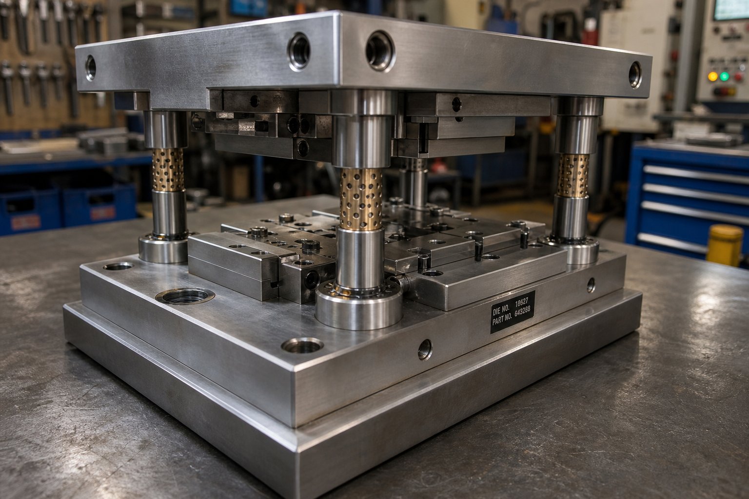
A stamping die set is the assembly of upper and lower die shoes, guide posts, and guide bushings that holds the two halves of a stamping die in precise alignment throughout the press stroke. It does not cut or form material - it ensures the components that do are positioned accurately every single time.
Think of it this way: the die set is the skeleton, and the cutting or forming details are the muscles. Without a rigid, well-aligned skeleton, even the sharpest punches and dies will produce inconsistent parts.
What a Stamping Die Set Actually Does
A stamp die set serves one fundamental purpose - maintaining alignment between the punch (upper half) and the die block (lower half) under immense force. The upper and lower die shoes distribute press load evenly, preventing localized deflection. Guide posts and bushings constrain lateral movement so the cutting edges meet with clearances often measured in tenths of a thousandth of an inch. This guidance system is what allows stamper dies to produce identical parts whether you're on cycle ten or cycle ten million.
Die sets also absorb and redirect side thrust generated during forming operations. Without this structural backbone, unbalanced forces would accelerate wear, degrade part tolerances, and eventually damage the press itself.
Die Set vs Die Block - Key Distinction
Here's where confusion often creeps in. A set of die components includes the shoes, posts, and bushings - the alignment infrastructure. The die blocks, by contrast, house the actual cutting edges, forming profiles, and piercing geometry. You can swap different die blocks into the same die set if the footprint matches, which is exactly why standardized die sets reduce tooling costs across product families.
This distinction matters because underperformance often traces back to the set rather than the die itself. Worn bushings, undersized shoes, or the wrong post configuration will degrade part quality regardless of how precisely your cutting geometry is ground. Configuration choices - post layout, bearing type, shoe material, and dimensional sizing - directly determine alignment accuracy, achievable tool life, and compatibility with your press equipment. Each of these variables compounds across production volume, making early decisions about your die set architecture one of the highest-leverage choices in any stamping program.
Core Components Inside Every Die Set
Every stamping die component plays a specific engineering role in keeping your tooling alive and your parts accurate. Yet most references simply list parts without explaining why they matter under load. When you understand what each piece actually does - and what happens when it fails - you can trace quality problems back to their root cause instead of chasing symptoms.
Upper and Lower Die Shoes Explained
The die shoes are the foundation of the entire die assembly. The upper shoe (also called the punch holder) carries the cutting and forming elements that move with the press ram. The lower shoe (the die holder) is clamped to the press bolster and supports the die plate, buttons, and any forming geometry mounted beneath the strip.
Imagine pressing your palm flat against a table - the force spreads evenly across your hand. Die shoes work the same way. They distribute concentrated press tonnage across a broad footprint so no single area of the die experiences destructive localized deflection. Shoe thickness is engineered relative to expected tonnage: too thin, and the shoe flexes mid-stroke, shifting clearances between die punches and their mating buttons. That flex might only be a few thousandths of an inch, but across millions of cycles it accelerates edge wear and produces burr growth on your stamped parts.
Most die shoes are machined from steel plate or cast iron, then ground flat and parallel. Flatness and parallelism are critical - any deviation translates directly into alignment error between the upper and lower halves of your tooling.
Guide Posts, Bushings and Alignment Systems
Guide posts are precision-ground, hardened steel cylinders pressed or clamped into one die shoe. They slide through matching guide bushings mounted in the opposite shoe, constraining lateral movement to tolerances within 0.0001 in. This is the mechanism that keeps your punch-to-die alignment consistent stroke after stroke.
Two main bushing styles exist. Friction bushings (plain bearing) use bronze or aluminum-bronze sleeves, sometimes embedded with graphite plugs for lubrication. Ball bearing bushings ride on caged ball bearings, delivering near-zero clearance and easier die separation. The choice between them affects precision capability, maintenance intervals, and how well the set handles side thrust - a topic covered in depth later in this article.
Post diameter and length also matter. Undersized posts deflect under lateral load, while posts that are too short allow the ball cage to exit the bushing during the stroke, damaging bearings and degrading alignment accuracy over time.
Auxiliary Components That Complete the Assembly
Beyond shoes and guide systems, several supporting components hold the die assembly together and protect it from damage:
- Backing plates - hardened steel plates placed behind die punches and buttons to prevent the punch heads from embedding into the softer shoe material under repeated impact.
- Heel blocks - steel blocks bolted to the upper and lower shoes with hardened wear plates that absorb side thrust. They prevent lateral shifting when cutting or forming forces are unbalanced.
- Dowel pins - precision-ground pins that locate die sections, retainers, and blocks in their exact position on the shoe. Screws hold components down; dowels hold them in place.
- Die springs - high-force compression springs (mechanical coil or nitrogen gas) that provide stripping force, pad pressure, or cam return force within the tool.
- Shank or clamp slots - the mechanical interface that secures the upper shoe to the press ram. Smaller dies use a shank pressed into the shoe center; larger dies rely on clamp slots machined along the shoe edges.
Each auxiliary part is a potential failure point. A cracked backing plate lets a punch head mushroom into the shoe. A worn heel block allows progressive lateral drift. A broken dowel lets a die section shift just enough to throw off your blanking clearances.
| Component | Function | Typical Material | Failure Indicator |
|---|---|---|---|
| Upper Die Shoe | Carries punch-side tooling; distributes ram force | Steel plate or cast iron | Surface galling, loss of parallelism |
| Lower Die Shoe | Supports die-side tooling; mounts to bolster | Steel plate or cast iron | Localized deformation under buttons |
| Guide Posts | Constrains lateral movement between shoes | Case-hardened or through-hardened tool steel | Visible wear lines, measurable diameter loss |
| Guide Bushings | Receives guide posts; maintains alignment tolerance | Bronze, aluminum-bronze, or steel (ball bearing type) | Increased clearance, scoring marks |
| Backing Plates | Prevents punch heads from embedding into shoes | Hardened tool steel | Cracking, dimpling, or mushrooming marks |
| Heel Blocks | Absorbs side thrust from unbalanced forces | Steel with hardened wear plates | Wear plate galling, visible clearance gap |
| Dowel Pins | Locates die sections precisely on shoes | Hardened alloy steel | Shearing, looseness in bore |
| Die Springs | Provides stripping, pad, or return force | Chrome-vanadium steel (mechanical) or nitrogen gas | Height loss exceeding 5%, cracking |
| Shank / Clamp Slots | Secures upper shoe to press ram | Integral to shoe (steel) | Elongation of slots, shank looseness |
You'll notice a pattern in that table: every failure indicator traces back to the same outcome - loss of alignment. That's because every stamping die component exists to maintain the spatial relationship between the upper and lower halves of the die. When any single element degrades, the guidance system compensates until it can't, and quality drifts quietly until someone notices bad parts downstream.
The real question, then, isn't just what's inside your die set - it's how you arrange those components. Post placement, count, and configuration determine how rigidity and accessibility trade off against each other, and the right layout depends entirely on the operation your tool needs to perform.
Die Set Configuration Types and When to Use Each
Post placement isn't an afterthought - it's a design decision that locks in the tradeoff between rigidity, alignment precision, and physical access to the die space. Four standard configurations cover the vast majority of press die set applications, yet most engineers inherit a layout rather than choosing one deliberately. Picking the wrong configuration for your operation introduces alignment problems that no amount of shimming or bushing replacement will solve.
Back Post and Center Post Configurations
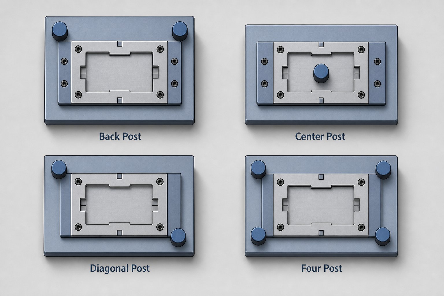
Back post sets position both guide posts along the rear edge of the die shoes, leaving the front and sides completely open. This is the most common layout for progressive and strip-fed dies because the open front provides unobstructed strip feeding, scrap removal, and operator visibility. If you're running a punch press die set for blanking or piercing with coil-fed stock, back post is almost always the starting point.
The tradeoff? Two posts at the rear create an asymmetric guidance condition. Under heavy cutting forces, the front of the die shoe is unsupported and more susceptible to deflection - especially on wider dies where the span between the post centerline and the working area is large. For narrow, high-speed progressive tools this rarely matters, but for wide dies with heavy forming stations near the front edge, back post sets can allow enough shoe tipping to shift punch-to-die alignment.
Center post sets solve this by placing the two guide posts on opposing sides - centered left and right - so the working area sits between them with balanced support. This geometry distributes lateral forces evenly, making center post stamp die sets the better choice for symmetrical blanking operations where side thrust loads are equal in all directions. The downside is reduced accessibility from both sides, which complicates strip feeding and makes manual part loading more difficult.
Diagonal and Four Post Configurations
Diagonal post sets position the two posts at diagonally opposite corners - typically rear-left and front-right. This opens two adjacent sides for access, making them well-suited for operations where parts or blanks are hand-loaded from the front or side. You'll find diagonal sets in secondary operations like notching or forming where automation isn't justified and operator reach matters.
Four post sets place a guide post at each corner of the die shoe. This delivers maximum deflection resistance and the most uniform guidance across the entire shoe surface. When tonnage climbs into hydraulic press die set territory - deep drawing, heavy coining, or high-force forming - four post configurations prevent the shoe tipping and localized flexing that two-post layouts can't resist. The compromise is obvious: access is restricted from all four sides, so strip feeding requires slot openings machined through the shoes, and die maintenance demands more teardown effort.
How to Match Configuration to Your Operation
Choosing the right layout comes down to three questions: How much rigidity does your process demand? Where does material enter and exit the die? And how will operators and automation interact with the tool during production?
A standard die for high-speed progressive stamping almost always uses a back post layout because feed access trumps the marginal rigidity gain of additional posts. Conversely, a heavy forming die running in a hydraulic press needs four posts because deflection control is the primary concern and strip access is irrelevant. Diagonal and center post configurations serve the middle ground - moderate tonnage operations where access requirements rule out the extremes.
| Configuration | Rigidity | Accessibility | Best Application | Relative Cost |
|---|---|---|---|---|
| Back Post (2 posts, rear) | Moderate | Excellent - open front and sides | Progressive dies, strip-fed blanking and piercing | Low |
| Center Post (2 posts, sides) | Moderate-High | Limited - restricted from both sides | Symmetrical blanking, balanced cutting | Low |
| Diagonal Post (2 posts, opposite corners) | Moderate | Good - two adjacent sides open | Manual-load secondary operations, notching | Low |
| Four Post (4 posts, all corners) | Maximum | Restricted - all sides partially blocked | Heavy forming, deep drawing, high-tonnage coining | Higher |
Notice that die sets for press applications under roughly 100 tons rarely justify four-post configurations - the additional cost and reduced accessibility aren't offset by meaningful rigidity gains at lower tonnages. But once forming forces generate significant lateral thrust or your shoe span exceeds what two posts can stabilize, stepping up to four posts eliminates the deflection-induced alignment drift that quietly degrades part quality over a production run.
Configuration determines the boundaries of what your guidance system can handle. But within any configuration, the type of bearing system - ball bearing or plain bearing - defines how precisely the posts and bushings maintain alignment under load, and how forgiving the set is when conditions aren't ideal.
Ball Bearing vs Plain Bearing Guide Systems
Your post configuration sets the structural framework. But the bearing system inside those posts and bushings determines how precisely that framework actually performs under load - and how quickly it punishes neglect. Two bearing philosophies dominate die tooling: ball bearing (rolling element) and plain bearing (friction). Both produce excellent parts. Both fail differently. Choosing between them isn't about which is "better" - it's about which one matches your operation's real conditions.
Ball Bearing Guide Systems and Precision Advantages
Ball bearing guide systems use caged ball bearings riding between the guide post outer diameter and the bushing inner diameter. These components operate in a preloaded condition - a rolling press fit with negative clearance, often as tight as 0.0001 to 0.0021 in. depending on the manufacturer and post diameter. That near-zero clearance is what delivers the alignment precision that tight-tolerance stamping demands.
Imagine the difference between sliding a drawer on wooden rails versus rolling it on ball bearings. The rolling action eliminates stick-slip, reduces heat buildup during continuous cycling, and maintains consistent alignment at speeds exceeding 200 strokes per minute. For precision die and stamping operations - high-speed blanking with punch-to-die clearances measured in tenths - ball bearing guidance earns its premium.
The catch? Ball bearing systems demand discipline. They don't tolerate contamination, rough handling, or inconsistent lubrication. A single misfeed that shock-loads the die can brinell the raceways, creating dents that produce "notchy" travel and progressive alignment drift. Compressed air blown carelessly around the guide system drives grit into the rolling path, where it gets rolled rather than embedded - accelerating damage instead of absorbing it. These failures often masquerade as punch wear or clearance problems, sending toolrooms on frustrating troubleshooting detours.
Refined mineral oil with extreme-pressure additives is the recommended lubricant - never grease, which traps contaminants in the negative-clearance assembly and inhibits proper bearing rotation.
Plain Bearing Systems and Their Durability Benefits
Plain bearing sets replace rolling elements with bronze, oil-impregnated bronze, or steel-backed bushings that support the guide post through a lubricated sliding interface. There's measurable clearance between post and bushing - typically a few tenths to a full thousandth - which means less raw precision than ball bearing systems, but significantly more forgiveness.
Where does that forgiveness matter? Everywhere conditions aren't ideal. Plain bearings tolerate contamination because particulates embed into the softer bushing material rather than cycling through the contact zone. They handle side thrust and shock loads without the catastrophic raceway damage that ends a ball bearing system's useful life. They survive the rough handling that happens during die changes on a busy press floor. And they keep working through lubrication lapses that would seize a rolling-element assembly.
For die and tooling applications involving heavy off-center forming, cam action, or environments with airborne grit and inconsistent maintenance routines, plain bearings fail more predictably. When they do wear, the symptom is gradual clearance growth - measurable, trackable, and correctable before quality suffers. That predictability alone makes them the preferred choice for many precision dies in forming and drawing operations where lateral thrust is a constant reality.
The cost trade is straightforward: plain bearing sets are less expensive to purchase and replace, but worn guide posts can develop scoring or taper that requires more involved correction than simply swapping a bushing.
When Hybrid Configurations Make Sense
Some tooling die applications don't fit neatly into one category. A progressive die might need tight alignment in the feed direction (where punch-to-pilot registration matters most) but experience significant side thrust perpendicular to feed from forming stations. Hybrid configurations address this by running ball bearing guidance on the critical axis and plain bearings on the thrust-loaded axis - capturing precision where it counts while absorbing abuse where it's inevitable.
| Criteria | Ball Bearing Guide System | Plain Bearing Guide System |
|---|---|---|
| Alignment Precision | Near-zero clearance (0.0001–0.0021 in. preload) | Measurable running clearance (0.0005–0.001 in. typical) |
| Load Capacity | Moderate - concentrated on individual ball elements | High - distributed across full bushing contact area |
| Maintenance Needs | Frequent lubrication with mineral oil; clean environment critical | Periodic lubrication; tolerates longer intervals |
| Environment Tolerance | Low - contamination causes accelerating damage | High - particulates embed rather than cycle |
| Shock Load Resistance | Poor - brinelling from impact events | Good - deforms gradually without catastrophic failure |
| Cost (Purchase) | Higher - precision rolling elements and cages | Lower - simpler bushing construction |
| Ideal Applications | High-speed blanking/piercing, tight tolerances, dedicated runners | Heavy forming, cam dies, high side thrust, dirty environments |
The guidance system you select defines what your stamping die set can tolerate - but it doesn't operate in isolation. The real performance test comes when you match both configuration and bearing type to the specific stamping operation your tool must perform. Blanking, piercing, forming, and drawing each place fundamentally different demands on die set rigidity and alignment accuracy.
Matching Die Sets to Specific Stamping Operations
Different stamping operations don't just require different punches and dies - they demand entirely different structural behavior from the die set beneath them. A blanking die running at 400 strokes per minute places alignment demands that have nothing to do with what a deep draw tool encounters at 15 strokes per minute. Yet many engineers select their die set configuration based on habit or availability rather than the actual physics of their process.
Here's a practical way to think about it: every operation falls somewhere on a rigidity demand spectrum. Some need extreme positional accuracy with minimal force. Others need massive structural resistance with more forgiving tolerances. Where your operation lands on that spectrum should drive every die set decision - post count, bearing type, and shoe thickness.
Die Sets for Blanking and Piercing Operations
Blanking and piercing are shearing processes. The punches and dies don't form material - they fracture it cleanly by driving a cutting edge through the sheet with tightly controlled clearance on all sides. That clearance, typically 5% to 10% of material thickness per side for mild steel, determines edge quality, burr height, and slug control. When your stamping die set allows even a few tenths of lateral shift during the cutting stroke, those clearances become uneven. One side tightens while the opposite side opens up, producing tapered slugs that stick in the die opening and parts with uneven burr patterns.
This is why progressive blanking operations overwhelmingly favor back post sets with ball bearing guides. The back post layout provides unobstructed strip feeding from the front, which matters when you're running coil stock at high speed with automated feeding. Ball bearing guidance delivers the near-zero clearance alignment that keeps every punching die station registered precisely to the strip pilots, stroke after stroke.
For a typical sheet metal punch and die set performing high-speed blanking, the alignment system must hold positional accuracy within half the die clearance. If your punch-to-die clearance is 0.003 in. per side, guidance system drift beyond 0.0015 in. starts producing visible quality degradation. Ball bearing sets routinely achieve this. Plain bearing sets can work for thicker materials with larger clearances, but they lack the positional repeatability that thin-gauge blanking demands.
Slug retention is another factor. When clearance shifts, slugs don't release cleanly - they wedge in the die opening or pull back onto the strip surface. In progressive sheet metal stamping dies, a stuck slug at station three means scrap parts from every downstream station. The rigidity penalty for losing alignment is amplified across the entire strip layout.
Die Sets for Forming and Drawing Operations
Forming and drawing operations play by different rules. Instead of fracturing material, forming dies bend, stretch, and compress it into new geometry. The dominant forces shift from vertical shearing to lateral thrust as material flows over forming radii, into cavities, and against pressure pads. That lateral thrust is what punishes die sets most aggressively.
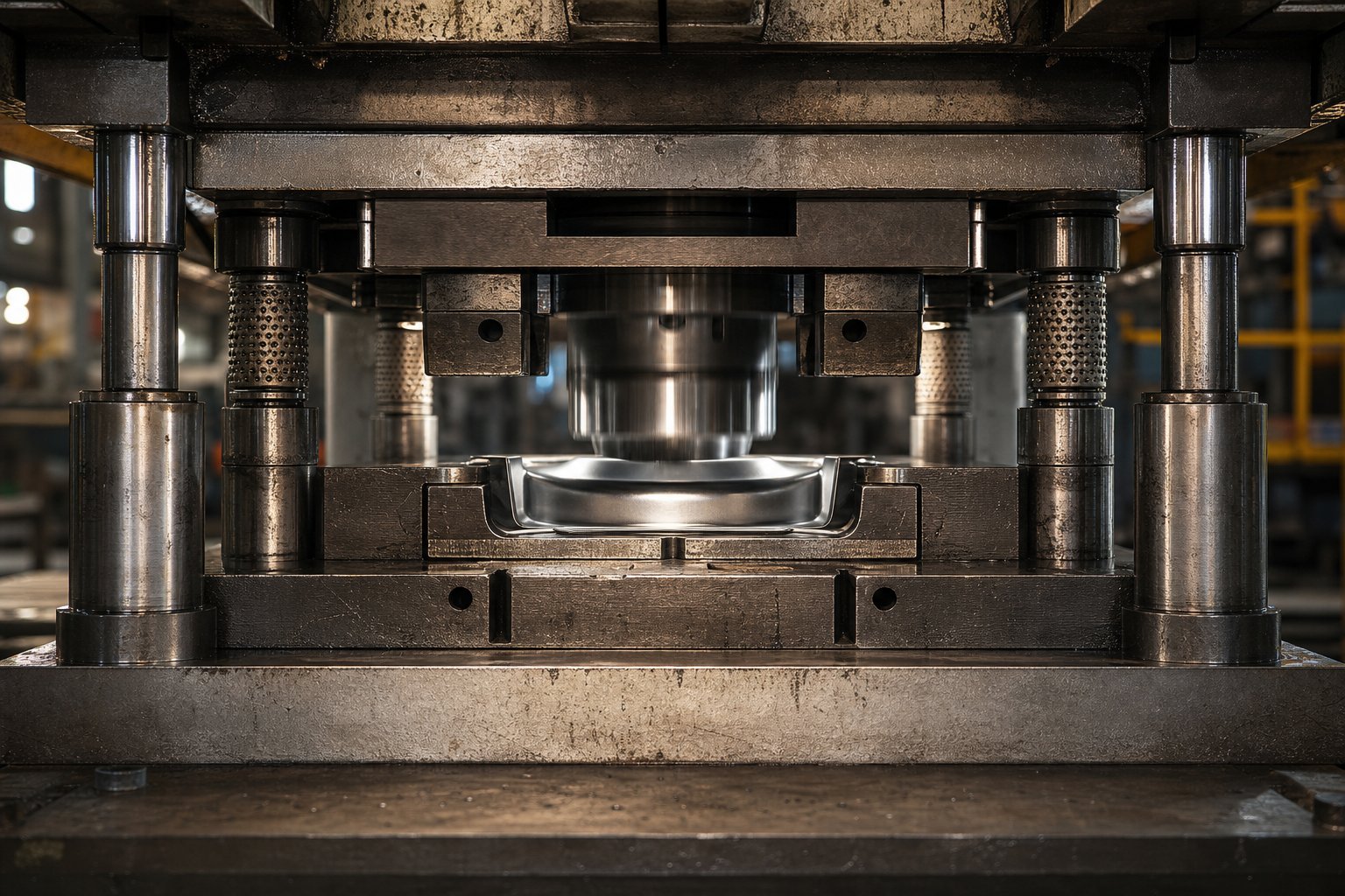
Consider a deep draw operation. As the punch pushes material into the draw cavity, the blank holder exerts pressure on the flange while material flows inward. Any asymmetry in blank shape, lubrication, or material thickness creates unbalanced horizontal forces that try to shift the upper shoe relative to the lower. According to research from the Institute for Metal Forming Technology, steering sheet metal flow between binders without wrinkling or cracking requires both precise blank holder pressure control and a die structure rigid enough to maintain uniform binder gap under load.
Four post configurations are the standard for deep drawing because they resist lateral thrust from all directions simultaneously. The four-corner guidance prevents shoe tipping regardless of where thrust forces originate, which matters because material flow in irregular draws rarely produces symmetric loading. Heavy die shoes - often 25% to 50% thicker than equivalent blanking applications - absorb the bending moment these thrust forces create without deflecting enough to change the punch-to-cavity relationship mid-stroke.
Plain bearing guidance often outperforms ball bearings here. The sustained side loads during a forming stroke would brinell ball bearing raceways over time, while bronze bushings absorb that thrust across their full contact surface without catastrophic damage. For metal stamping dies performing heavy bending or drawing, the predictable wear pattern of plain bearings is actually an advantage - you can measure clearance growth and schedule replacements before part quality drifts.
How Material Flow Drives Configuration Decisions
Beyond force magnitude, the way material enters, moves through, and exits your die constrains which configurations are even possible. Strip width determines whether a back post layout provides sufficient shoe area to mount guide posts behind the working envelope. Feed direction dictates which sides must remain open for coil access and loop control. Scrap removal paths - where slugs fall, how trim skeletons exit - require clear channels that guide posts cannot obstruct.
In progressive metal stamping dies, the strip advances one pitch per stroke while remaining attached to a carrier. Formed features at downstream stations protrude above and below the strip plane, requiring clearance as the strip lifts and advances. Back post sets accommodate this easily because the open front allows formed features to pass without interference. Four post sets would block the strip path unless clearance slots are machined through the shoes - adding cost and potentially weakening the very structure you chose for rigidity.
A forming die with cam-actuated side operations needs access from specific directions for cam slides and their return mechanisms. Diagonal post sets often work here because they open two adjacent sides for cam mounting while still providing guidance from opposite corners. Material flow characteristics - whether the workpiece stretches, compresses, or slides during forming - also influence shoe thickness decisions. Operations involving significant material compression, like coining, generate higher vertical force per unit area, demanding thicker shoes to prevent localized deflection beneath the working steels.
The following ranking helps frame how die set rigidity requirements escalate across common operations:
- Simple piercing - lowest demand; small cutting perimeters, minimal side thrust, thin stock. Back post with ball bearing guidance handles most applications.
- Blanking - moderate demand; larger cutting forces, slug control critical. Back post or center post with ball bearing guidance.
- Bending - moderate-high demand; off-center forces create localized thrust. Center post or diagonal post with plain or hybrid bearings.
- Forming (embossing, flanging) - high demand; material flow generates sustained lateral loads. Four post preferred; plain bearings resist sustained thrust.
- Deep drawing - highest demand; large lateral thrust from asymmetric material flow, heavy blank holder forces, long working strokes. Four post with heavy shoes and plain bearing guidance required.
Each step up that list adds lateral force complexity. A punching die at the bottom of the spectrum succeeds or fails based almost entirely on vertical alignment precision. A forming die at the top succeeds or fails based on the set's ability to resist sustained horizontal loads without deflecting. Understanding where your operation falls on this spectrum - and sizing your die set accordingly - is the difference between a tool that delivers consistent parts for years and one that starts drifting within months.
Rigidity and configuration get you into the right ballpark. But unless your die set physically fits the press it's going into - matching bed dimensions, shut height, stroke length, and clamping provisions - none of those design choices matter. The sizing and compatibility verification process is where many programs stall.
How to Size a Die Set for Press Compatibility
A perfectly configured die set with the right posts, bearings, and shoe material still fails if it doesn't physically fit the press it's assigned to. Sizing errors are among the most expensive mistakes in stamping tooling - they surface late in the build process, delay tryouts, and sometimes force costly rework of components already hardened and ground. The fix is straightforward: verify every critical dimension before the purchase order goes out.
Calculating Die Shoe Dimensions From Die Space
Die shoe size starts with the working envelope - the area occupied by all active die components including cutting sections, forming steels, pilots, lifters, and scrap cutters. But the shoe can't simply match that footprint. You need clearance beyond the working area for several things: fastener access (socket head cap screws and dowel pins), guide post mounting locations, heel block placement, and strip feed passage.
A practical rule: add a minimum of 2 to 3 inches beyond the active die area on each side where guide posts won't be placed, and 3 to 4 inches on the sides where posts mount. For progressive dies, the feed-direction edges need additional length to accommodate pilot locations outside the last working station and any strip guidance rails. Undersizing the shoe to save material is a false economy - it forces components too close together, making maintenance access difficult and leaving insufficient metal between mounting holes, which weakens the shoe under load.
Width and depth also need to respect the press bolster dimensions. Your shoe footprint must sit within the bolster area with enough margin for clamps or T-bolt heads. If the shoe extends beyond the bolster support, unsupported edges deflect under tonnage, creating the same localized flex that ruins part accuracy.
Shut Height and Stroke Compatibility
Shut height is where press die compatibility most commonly breaks down. The concept sounds simple, but the terminology trips up even experienced engineers because press shut height and die shut height are distinct measurements that must be reconciled.
Press shut height is the distance from the bottom face of the ram to the top of the press bed, measured with the ram at bottom dead center and the adjustment set to its full-up position. This is the maximum vertical space the machine offers. Die height - the usable space for your tooling - is smaller: subtract the bolster plate thickness from the press shut height to get maximum die height. Subtract the ram adjustment range from that number to get minimum die height.
Your die's shut height (total stack-up in the closed position, from the bottom of the lower shoe to the top of the upper shoe) must fall between those minimum and maximum values. If the die is taller than maximum die height, it physically won't close. If it's shorter than minimum die height, the ram adjustment can't reach it - and you'll need parallel blocks or risers to make up the difference, which adds stack-up uncertainty and maintenance steps.
For hydraulic press dies with longer strokes and variable speed profiles, also verify that the stroke length provides enough open daylight for strip feeding, part ejection, and any cam or slide return travel. A press die punch that enters the material before cams have fully deployed will destroy both the tooling and the workpiece.
Verifying Press-to-Die-Set Fit
Before committing to die sets for presses in your facility, run through this verification checklist. Every dimension on it can be confirmed from the press specification plate, the machine's technical manual, or direct measurement:
- Bolster area - confirm shoe footprint fits within bolster dimensions with clearance for clamping on all secured edges
- T-slot pattern and size - verify slot spacing and width accommodate your preferred clamping method (T-bolts, strap clamps, or hydraulic clamps)
- Maximum die height - press shut height minus bolster thickness; your closed die stack must be less than this value
- Minimum die height - maximum die height minus ram adjustment range; your closed die stack must exceed this value
- Stroke length - sufficient clearance for material feed height, part ejection, and cam return at full open position
- Tonnage rating - total cutting and forming force must remain below rated press capacity, with a 20-30% safety margin to account for material variation and tool wear
- Ram connection - shank diameter matches ram bore (for smaller punch press dies) or clamp slot spacing aligns with ram T-slots (for larger tools)
- Scrap clearance - bolster openings or clearance beneath the lower shoe allow slugs and trim scrap to exit without accumulation
- Feed height - open daylight at top of stroke accommodates coil feed line height and any loop requirements
- Parallelism specification - press ram face and bolster surface parallelism are within specification; worn presses amplify any die set alignment issues
One detail engineers frequently overlook: clamp accessibility. Your shoe dimensions might fit the bolster, but if guide posts, heel blocks, or nitrogen cylinders block the clamping zones along the shoe perimeter, you can't secure the die properly. Sketch the clamp locations relative to all mounted components before finalizing shoe dimensions.
Also confirm that punch dies for press assignments within your plant share standardized shut heights where possible. Standardizing die height across tools running in the same press minimizes ram adjustment during changeovers, reducing setup time and eliminating the re-calibration errors that creep in when operators repeatedly adjust between widely different settings.
Dimensional compatibility gets your die set into the press. But once it's there, the materials those shoes, posts, and bushings are made from determine how the assembly behaves under repeated loading - whether it holds alignment over millions of cycles or gradually drifts as components deflect and deform.
Material Selection and Structural Rigidity
Even when your die set is correctly sized for the press and configured with the right post layout, the materials those components are made from ultimately control what happens under repeated loading. A properly dimensioned shoe made from the wrong material flexes in ways that slowly degrade part quality. A guide post without adequate hardness develops wear patterns that introduce clearance growth within the first few production runs. Material selection isn't glamorous, but it's where long-term stamping accuracy is either locked in or quietly lost.
Die Shoe Materials and Their Performance Tradeoffs
Three material families dominate die shoe construction, each with a distinct performance profile that fits specific production scenarios.
Steel plate is the default for most metal press dies. Low-carbon steel (typically AISI 1020 or 1030) offers high stiffness, easy machinability, and straightforward repairability. If a screw or dowel hole lands in the wrong spot, steel shoes can be plugged and welded without compromising structural integrity. Steel's elastic modulus - roughly 30 million psi - resists bending under tonnage better than any alternative at comparable thickness. For steel stamping dies running production volumes in the hundreds of thousands or millions, steel plate is the safe, cost-effective foundation.
Cast iron shoes trade some stiffness for superior vibration dampening. The graphite microstructure in gray iron absorbs the shock energy generated during blanking snap-through - that sudden release of stored energy when a punch breaks through the material. This dampening reduces noise, extends punch life, and minimizes the cyclic fatigue that propagates microcracks through hardened tool steels over time. Larger automotive dies often use precisely guided cast-iron foundations shaped to each specific part rather than flat plate shoes.
Aluminum shoes weigh roughly one-third as much as steel and machine significantly faster. Special alloys like QC-7 and QC-10 deliver compressive strength exceeding that of low-carbon steel, making them viable for production - not just prototyping. Aluminum excels in high-speed blanking applications where reduced die weight translates to less press ram inertia, faster cycling, and lower noise levels. The material also dissipates heat more effectively than steel, which benefits operations generating friction-related temperature buildup. The drawbacks are real, though: aluminum shoes cost more, are harder to repair if holes are mislocated, and lack the long-term wear resistance of steel in heavy forming applications.
Shoe thickness matters as much as material choice. When a sheet metal die operates with the shoe resting on parallels - raised blocks that create clearance for scrap to fall - the unsupported span between parallels behaves like a beam under load. A thin shoe over a wide span deflects at the center, changing punch-to-die clearances dynamically during each stroke. This deflection might measure only a few tenths of a thousandth, but across millions of cycles it accelerates edge wear asymmetrically, producing burr growth on one side of the stamped part while the opposite edge remains clean. The cumulative effect is part quality drift that worsens gradually until tolerances are exceeded and scrap rates spike.
There's no single formula for ideal shoe thickness because the variables compound: tonnage, span width, support conditions, material stiffness, and whether the load is concentrated (piercing) or distributed (forming). But the principle is consistent - undersized shoes deflect, deflection shifts clearances, and shifted clearances kill part quality over time. If you're seeing progressive dimensional drift in a sheet metal die that passed initial tryout without issues, insufficient shoe thickness or stiffness is among the first root causes to investigate.
Guide Post and Bushing Material Specifications
Guide posts endure a punishing duty cycle: they resist lateral thrust, absorb shock loads during snap-through, and maintain sliding fit with their bushings across millions of strokes. Material selection here directly determines how long the guidance system holds alignment before clearance growth forces replacement.
Two hardening approaches dominate the metal tool and die industry for guide posts:
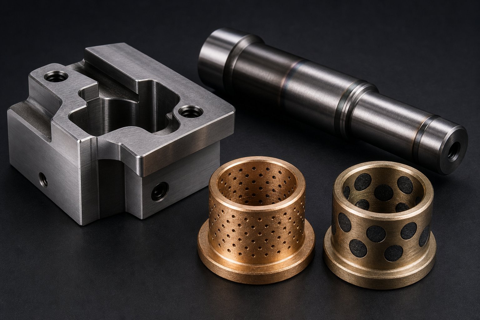
- Case-hardened steel - a low-carbon core (typically 8620 or similar) carburized to produce a hard surface shell (58-62 HRC) over a tough, ductile interior. The hard case resists surface wear and scoring while the soft core absorbs impact without brittle fracture. Case-hardened posts are the standard for most metal forming dies because they balance wear resistance with toughness.
- Through-hardened tool steel - a medium-carbon alloy steel (like O1 or A2) heat-treated to uniform hardness throughout the cross section (58-60 HRC). Through-hardened posts offer slightly higher rigidity under lateral load because the entire section resists deflection equally. They're specified for precision applications demanding the tightest guidance tolerances, but they're more brittle under impact and more expensive to manufacture.
Bushing material must be softer than the post it rides against - this ensures wear concentrates in the replaceable bushing rather than the more expensive post. Common bushing alloys include:
- Bronze (C93200 or C93700) - excellent wear resistance and natural lubricity from the tin content. Good thermal conductivity helps dissipate heat from friction. The standard choice for plain bearing die sets.
- Oil-impregnated bronze - sintered bronze with interconnected porosity saturated with lubricating oil. The porous structure releases oil under pressure and heat, providing self-lubrication during operation. Ideal for applications where manual lubrication intervals are inconsistent.
- Steel-backed bronze - a thin bronze bearing layer bonded to a steel shell. The steel backing provides structural strength while the bronze surface provides the wear and friction characteristics. Used in high-load applications where a solid bronze bushing might deform under compressive force.
- Graphite-plugged bronze - solid bronze bushings with embedded graphite plugs that provide continuous self-lubrication. Best suited for high-temperature environments or applications where liquid lubricant would contaminate the workpiece.
Surface treatments extend component life beyond what base material properties alone provide. Nitriding guide posts after hardening adds a thin, extremely hard nitrogen-diffused layer (up to 70 HRC surface) that resists galling and adhesive wear without changing core properties. Chrome plating adds corrosion resistance and reduces friction coefficients on sliding surfaces. For metal die applications in corrosive environments or where lubricant contamination is an issue, these surface treatments can double or triple the interval between post replacements.
Heat treatment specifications deserve attention during procurement. Posts that aren't tempered adequately after hardening retain internal stresses that relieve themselves over time - causing dimensional changes that shift your guidance alignment after the die is already in production. Always verify that posts are double or triple tempered per the steel manufacturer's recommendation, and confirm hardness values at receiving inspection rather than trusting paperwork alone.
| Material | Stiffness (Elastic Modulus) | Vibration Damping | Weight | Relative Cost | Best Application |
|---|---|---|---|---|---|
| Low-Carbon Steel Plate (1020/1030) | High (30 Msi) | Low | Heavy | Low | General production dies, forming, progressive |
| Cast Iron (Gray Iron) | Moderate-High (14-21 Msi) | High | Heavy | Moderate | High-speed blanking, noise-sensitive operations, large automotive dies |
| Aluminum Alloy (QC-7, QC-10) | Low (10.4 Msi) | Moderate | Light (1/3 of steel) | Higher | High-speed stamping, prototype sets, weight-limited applications |
| Case-Hardened Steel (8620 posts) | High (30 Msi) | Low | Heavy | Moderate | Standard guide posts for production metal forming dies |
| Through-Hardened Tool Steel (O1/A2 posts) | High (30 Msi) | Low | Heavy | Higher | Precision guidance requiring maximum wear resistance |
| Bronze Alloy (C93200 bushings) | Moderate (14 Msi) | Moderate | Moderate | Moderate | Plain bearing bushings for standard and heavy-load applications |
| Steel-Backed Bronze (bushings) | High backing / Moderate surface | Low | Moderate | Higher | High-load bushings where solid bronze would deform |
Material choices compound over production life. A steel shoe paired with case-hardened posts and oil-impregnated bronze bushings delivers millions of reliable cycles in most stamping applications. But if your environment, tonnage, or precision requirements push beyond standard conditions, upgrading even one component - a thicker shoe, through-hardened posts, or graphite-plugged bushings - can eliminate the failure mode that's been quietly shortening your die life. The key is knowing which component is limiting your system, and that requires understanding the wear patterns and failure indicators that each material exhibits under service conditions.
Die Set Maintenance and Troubleshooting
Wear patterns don't announce themselves with alarms. They develop slowly - a few tenths of clearance growth here, a faint scoring mark there - until the cumulative effect finally surfaces as dimensional drift in your stamped parts. By then, the damage has already cascaded: worn bushings have allowed misalignment that accelerated punch edge breakdown, which increased cutting forces, which further punished the guidance system. Breaking that cycle requires a disciplined inspection routine that catches degradation early, before it compounds into costly die tool failures or unplanned press downtime.
Wear Indicators and Measurement Methods
Guide post and bushing clearance is the single most telling measurement of die set health. When a set is new, the running clearance between a plain bearing bushing and its mating post is typically 0.0003 to 0.001 in. - just enough for a lubricant film without perceptible play. Over millions of cycles, that clearance grows as the softer bushing material wears against the hardened post. Tracking that growth over time tells you exactly how much useful life remains.
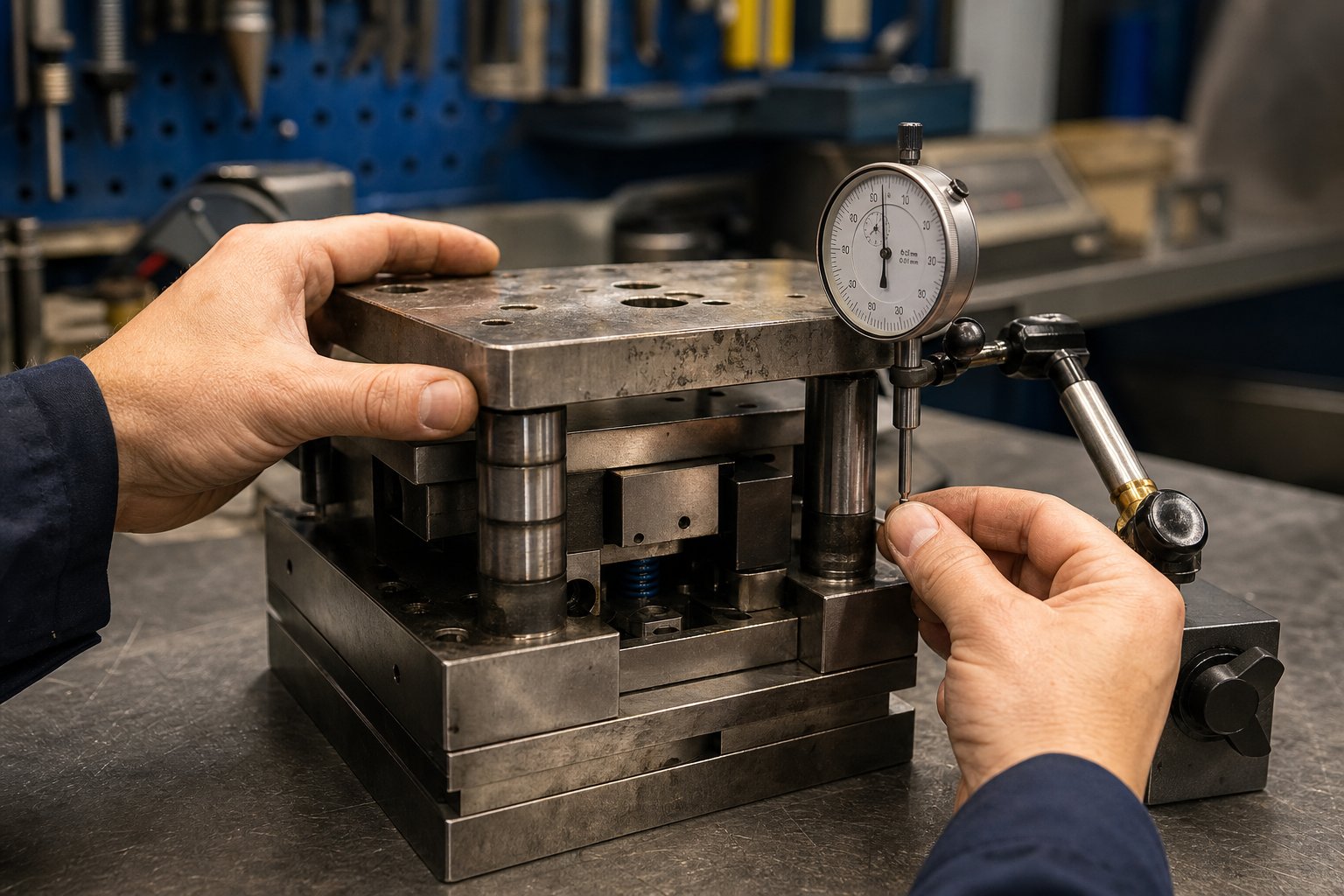
Here's how to measure it: with the die set removed from the press, mount a dial indicator on the lower shoe and position the plunger against the upper shoe near the guide post. Apply lateral hand pressure to the upper shoe and read the total indicator movement. That's your functional clearance - the actual play the guidance system allows during operation. Compare this reading against the original specification from the die build record.
Replacement thresholds depend on part tolerance requirements, but a practical guideline is this: when measured clearance exceeds three times the original specification, schedule bushing replacement at the next planned maintenance window. When it exceeds five times the original, pull the die from production immediately - you're running on borrowed time, and part quality is already degrading even if inspection hasn't flagged it yet.
Beyond clearance measurement, inspect guide posts visually for these indicators:
- Vertical scoring or galling lines - indicate lubrication starvation or contamination in the sliding interface
- Polished wear bands - show where the bushing contacts under load; uneven bands indicate the post is deflecting or the shoes aren't parallel
- Ball tracking marks - on ball bearing systems, grooves worn into the post OD or bushing ID reveal excessive side loading that transfers to individual ball elements in point contact
- Diameter taper - measurable with a micrometer at top, middle, and bottom of the post engagement zone; taper beyond 0.0002 in. indicates the post itself needs replacement, not just the bushing
Shoe surfaces require their own inspection protocol. Run a straight edge across the mounting surfaces and check for light gaps indicating localized deformation - especially beneath hardened die sections where concentrated punch loads have been peening the softer shoe material over time. Fretting marks (fine rust-colored powder at mating interfaces) signal that bolted components are micro-moving under cyclic load, wearing away base material and loosening the fit. Galling on heel block contact surfaces shows the wear plates have exceeded their useful life and lateral forces are now damaging the shoe itself.
Shoe parallelism - the flatness relationship between upper and lower mounting surfaces - should be verified with a dial indicator swept across the surface on a granite reference plate. When parallelism deviation exceeds 0.001 in. across the shoe width, the shoes need re-grinding on a surface grinder to restore the precision that machining dies and cutting sections depend on for uniform clearance.
Common Failure Modes and Root Causes
Most die set failures trace back to one of three root causes: lubrication breakdown, overloading, or misalignment. The failure mode itself is the symptom - fixing it without addressing the underlying cause guarantees a repeat event. Every die shop technician should be able to recognize these patterns and trace them to their source.
| Failure Mode | Symptom | Root Cause | Corrective Action |
|---|---|---|---|
| Bushing seizure | Upper shoe binds during press stroke; scoring or welding between post and bushing | Lubrication starvation - oil passages blocked, manual lube skipped, or wrong lubricant type used | Replace bushing; clean and inspect post for damage; restore lubrication schedule; verify lubricant specification matches bearing type |
| Guide post breakage | Sudden loss of alignment; visible fracture at or near the shoe mounting surface | Chronic misalignment between press ram and bolster; worn press gibs allowing angular deflection that bends the post each stroke | Replace post; inspect press parallelism and gib clearance; verify shoe mounting is fully seated; check for heel block contact before post engagement |
| Shoe cracking | Visible crack propagating from screw hole, keyway, or sharp internal corner on shoe | Overloading - tonnage exceeds shoe capacity; stress concentration at geometric discontinuities accelerated by fatigue cycling | Retire shoe if crack extends beyond repair zone; verify actual tonnage against design capacity; increase shoe thickness or material grade on replacement |
| Accelerated bushing wear (one side) | Uneven clearance readings; wear band concentrated on one side of bushing ID | Unbalanced die forces generating sustained side thrust in one direction; or press ram tilting under load | Add or inspect heel blocks to absorb lateral thrust; verify press ram parallelism; consider upgrading to steel-backed bushings for higher load capacity |
| Post brinelling (ball bearing sets) | Notchy or rough travel during die opening/closing; visible dents on post surface | Shock loading from misfeed, double-hit, or slug stacking event that overloads individual ball elements | Replace post and ball cage assembly; investigate misfeed detection system; add slug sensors if not present |
| Shoe surface deformation | Progressive dimensional drift in stamped parts; backing plate impressions visible on shoe surface | Missing or cracked backing plate allowing hardened punch heads to peen directly into softer shoe material | Replace backing plates; re-grind shoe surface flat; verify all die tools and backing plates are present and undamaged before next run |
Notice the pattern: every corrective action includes both an immediate fix and an investigation step. Replacing a seized bushing without checking lubrication delivery is just scheduling the next seizure. Die maker tools like bore gauges, dial indicators, and surface plates exist specifically to quantify these conditions objectively - relying on visual inspection alone misses the early-stage degradation that predictable maintenance is designed to catch.
Preventive Maintenance Schedule
Maintenance frequency should scale with production volume. A die running 50,000 strokes between service intervals in a high-volume automotive plant needs a different rhythm than one producing 5,000 parts per run in a job shop. The following tier structure provides a baseline - adjust intervals based on your actual wear measurement trends and part quality data.
Tier 1: Every production run (or every 10,000-25,000 strokes)
- Wipe guide posts and bushings clean; inspect for scoring, heat discoloration, or dry surfaces
- Apply specified lubricant to all guide post and bushing interfaces
- Check heel block wear plates for galling or debris buildup
- Verify all shoe mounting bolts are torqued to specification
- Inspect for loose dowel pins by visual check and light tap test
- Clean slug and scrap buildup from shoe clearance areas
Tier 2: Every 50,000-100,000 strokes
- Measure guide post-to-bushing clearance with dial indicator method; record and trend values
- Inspect shoe mounting surfaces for fretting, galling, or deformation
- Check backing plates for cracks, dimpling, or mushrooming
- Verify spring free heights against original specifications; replace any showing more than 5% height loss
- Inspect guide post surfaces with micrometer at three points for taper or diameter reduction
- Examine ball bearing cages (if applicable) for cracked retainers or missing balls
Tier 3: Every 250,000-500,000 strokes (or annually for low-volume die machining applications)
- Remove die set from service for comprehensive bench inspection
- Check shoe parallelism on granite surface plate; re-grind if deviation exceeds 0.001 in.
- Replace all bushings showing clearance beyond three times original specification
- Replace all guide posts showing measurable taper, scoring below surface finish specification, or diameter reduction beyond 0.0005 in.
- Inspect all dowel pin bores for elongation; ream and fit oversized pins if necessary
- Verify shoe thickness at high-load areas hasn't decreased from surface deformation
- Re-qualify shoe flatness and parallelism after any regrinding operation
Retirement criteria: A die set should be retired from production when shoe cracks extend beyond local repair, when re-grinding has reduced shoe thickness below the minimum required for the application's tonnage, when guide post bore locations have worn to the point where standard oversized posts can't restore original alignment, or when cumulative deformation has shifted the geometric relationship between mounting features beyond what shimming can compensate. At that point, the set has delivered its designed service life - and every additional stroke is a gamble against catastrophic failure.
Consistent maintenance transforms a die set from a consumable into a long-lived capital asset. But maintenance only preserves what was correctly specified in the first place. Getting that original specification right - communicating the correct dimensions, tolerances, and performance requirements to your supplier - is where the final piece of the puzzle falls into place.
How to Specify and Order the Right Die Set
Maintenance keeps your die set performing - but it can't fix a set that was incorrectly specified from day one. Ordering a stamping die set without communicating the right data to your supplier is like asking a machinist to cut a part without a print. You'll get something back, but it probably won't fit your press, match your process, or last through your production volume. The specification stage is where tooling engineers lock in performance or unknowingly build in limitations.
Information You Need Before Specifying a Die Set
Before contacting any stamping dies manufacturer, gather the following data points. Missing even one can result in a set that requires rework or doesn't fit your press at all:
- Press tonnage rating - determines shoe material grade and minimum thickness to resist deflection under your maximum load
- Bolster dimensions (width x depth) - constrains maximum shoe footprint and clamping zone locations
- Shut height range (minimum and maximum) - defines the vertical envelope your closed die stack must fit within
- Stroke length - affects guide post engagement length; posts must remain in bushings throughout the full open position
- Feed direction and strip width - determines which sides must remain clear of guide posts and heel blocks
- Production volume expectation - drives material selection, bearing type, and surface treatment decisions
- Die space envelope (working area dimensions) - sets the minimum shoe area needed to mount all active die components with clearance for fasteners
- T-slot pattern and size - ensures the shoe can be properly clamped to both bolster and ram
- Part tolerance requirements - determines whether ball bearing or plain bearing guidance is appropriate
- Operating environment - dust, coolant mist, or temperature extremes affect bushing material and lubrication specifications
Sounds like a lot? It is - but every item on that list corresponds to a dimension or material choice your supplier will make on your behalf if you don't specify it. Taking control of these decisions upfront is what separates a custom die that performs from one that merely fits.
Standard vs Custom Die Sets and Cost Considerations
Production volume is the primary lever in the standard-versus-custom decision. Standard catalog die sets - built to common dimensions with predetermined post sizes, locations, and shoe thicknesses - offer fast delivery and lower unit cost through economies of scale. As industry experience shows, most facilities cannot produce a one-off die set as cost-effectively as a specialty die manufacturing supplier operating at volume. Standard sets also offer interchangeability: components conform to NAAMS or JIS dimensional standards, meaning replacement posts, bushings, and shoes can be sourced from multiple die manufacturers without custom machining.
Custom metal stamping dies earn their premium when your application falls outside catalog parameters. Non-standard post spacing, oversized shoes for heavy-tonnage forming, unusual feed-direction clearance requirements, or the need for integrated heel blocks and nitrogen mounting pockets all push you toward a custom die kit engineered to your exact specifications. The cost difference is real - custom solutions require dedicated engineering time, unique setups, and often longer lead times - but so is the performance gap when a catalog set forces compromises in your die layout.
A middle path exists too. Some engineers purchase a standard set and then machine custom features in-house - additional mounting holes, clearance pockets, or modified post locations. This hybrid approach can shorten timelines, but it requires the machining capability and expertise to maintain the positional accuracy between guide post bores that die set performance depends on. Single-setup machining of all critical features, as precision-focused suppliers practice, eliminates the positional errors that compound when a die shoe moves between multiple machine setups.
Lead time planning also matters. Standard die sets often ship within days. Custom metal stamping die orders typically run two to six weeks depending on complexity, material availability, and the supplier's backlog. For production launches with fixed deadlines, factor this lead time into your tooling program schedule - not as an afterthought, but as a critical-path item that gates tryout and validation.
Partnering With the Right Die Set Supplier
The specification data you've gathered only delivers results if your supplier knows what to do with it. Look for die manufacturers who ask the right questions back - about your process, your press condition, and your tolerance expectations - rather than simply quoting to a drawing. The best suppliers function as engineering partners, catching specification gaps before they become build errors.
For projects involving complex die structures - tight clearance specifications, optimized material flow, custom punches, lifters, or bypass notch geometry - working with a supplier who bridges design intent and manufacturing reality saves iteration cycles. YICHEN, for example, connects tooling engineers to custom stamping die solutions that address design-heavy challenges like burr control, component integration, and clearance optimization from the outset, rather than leaving those details to be resolved during tryout.
Regardless of which supplier you choose, confirm these capabilities before committing: in-house machining with probed verification of critical dimensions, documented quality reports showing actual tolerances achieved, and the willingness to collaborate on specification refinement rather than simply building to print. A stamping die set is a precision instrument that determines your part quality for years - the ordering process deserves the same rigor you'd apply to specifying any other capital tooling investment.
Stamping Die Set FAQs
1. What is the difference between a die set and a die block?
A die set is the structural framework consisting of upper and lower die shoes, guide posts, and guide bushings that maintains alignment between the two halves of a stamping tool. Die blocks, on the other hand, contain the actual cutting edges, forming profiles, and piercing geometry. You can swap different die blocks into the same die set as long as the footprint matches, which is why standardized die sets help reduce tooling costs across product families. When part quality degrades, the root cause often traces back to the die set's worn guidance system rather than the die block geometry itself.
2. How do I choose between ball bearing and plain bearing guide systems for my die set?
The choice depends on your operating conditions. Ball bearing systems deliver near-zero clearance alignment ideal for high-speed blanking and tight-tolerance piercing, but they require clean environments, consistent lubrication with mineral oil, and cannot tolerate shock loads or contamination. Plain bearing systems use bronze bushings that handle side thrust, dirty environments, and inconsistent maintenance far better, making them suited for heavy forming, deep drawing, and cam-action dies. For progressive dies with both precision and thrust demands, hybrid configurations running ball bearings on the critical feed axis and plain bearings on the thrust-loaded axis offer an effective compromise.
3. When should I replace guide bushings in a stamping die set?
Schedule bushing replacement when measured post-to-bushing clearance exceeds three times the original specification from the die build record. If clearance reaches five times the original value, pull the die from production immediately as part quality is already degrading. Measure clearance by mounting a dial indicator on the lower shoe, positioning the plunger against the upper shoe near the guide post, and reading total indicator movement under lateral hand pressure. Track these readings over time to predict replacement intervals and avoid unplanned downtime.
4. What die set configuration is best for progressive stamping?
Back post configurations are the standard for progressive stamping because they position both guide posts along the rear edge, leaving the front and sides completely open for strip feeding, scrap removal, and operator visibility. Paired with ball bearing guidance, back post sets provide the positional repeatability that high-speed progressive blanking and piercing require. However, if your progressive die includes heavy forming stations near the front edge of a wide shoe, the asymmetric guidance of two rear posts may allow enough deflection to shift alignment. In those cases, consider upgrading to a four-post layout or adding heel blocks to absorb lateral thrust.
5. How do I determine the correct die shoe thickness for my application?
Shoe thickness must resist deflection under your specific tonnage, span width, and support conditions. When a shoe rests on parallels for scrap clearance, the unsupported span behaves like a loaded beam. A shoe that is too thin deflects at center, dynamically shifting punch-to-die clearances each stroke and causing progressive burr growth and dimensional drift. While no single formula covers all cases, the principle is consistent: higher tonnage, wider unsupported spans, and concentrated piercing loads all demand thicker shoes. If you observe progressive quality drift in a die that passed initial tryout, insufficient shoe thickness is among the first root causes to investigate. Suppliers like YICHEN can help engineers optimize shoe dimensions relative to specific tonnage and clearance requirements.


