


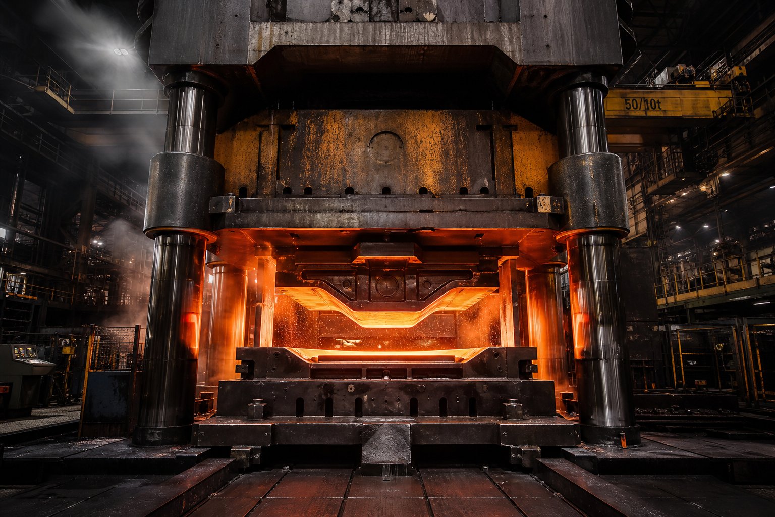
What Qualifies as a Large Part in Die Stamping
When does a stamped metal component cross the line from "standard" into "large part" territory? The industry talks about heavy metal stamping constantly, yet rarely draws a clear boundary. If you're scoping out a die stamping service for large parts, you need hard numbers before you can even begin evaluating feasibility.
Defining Large Parts in Die Stamping
A part generally qualifies as "large" in die stamping when it exceeds 24 inches in any single dimension or when it requires a press bed larger than 72 inches to accommodate the tooling. But dimensions alone don't tell the whole story. Material thickness plays a defining role: parts stamped from stock above 3mm (roughly 0.120 inches) enter heavy gauge territory, where the physics of forming shift dramatically. According to Worthy Hardware's overview of heavy gauge stamping, this process typically handles materials ranging from 0.079 inches to 0.5 inches thick, sometimes even thicker, requiring presses capable of exerting several hundred tons of force.
Weight matters too. When a finished blank or formed component exceeds what an operator can safely position by hand, you're dealing with parts that demand mechanical handling, robotic transfer, or dedicated automation. Think progressive stamped automotive parts like full-length frame rails, structural cross members, or large bracket assemblies. These components can weigh anywhere from 10 to over 100 pounds in their finished state.
Why Part Size Changes Everything
Imagine doubling the footprint of a stamped part. You haven't just doubled the challenge. You've compounded it. Material flow becomes harder to control across a larger surface. Maintaining flatness on a 36-inch blank requires uniform pressure distribution that smaller parts never demand. Registration accuracy, the ability to keep every forming station aligned to the same datum, degrades as blank dimensions grow.
In auto metal stamping, engineers designing automotive components progressive stamping lines face these scaling problems daily. A fender bracket that's 8 inches wide behaves predictably. Scale that concept to a full structural panel, and every tolerance stack-up, every springback variation, and every strip feed inconsistency amplifies across the larger geometry.
Here's what separates standard stamping from large-part work at a practical level:
- Blank handling - Large blanks require dedicated feeding systems, coil cradles rated for heavier coils, and servo feeds with extended stroke lengths
- Tonnage demands - Force requirements scale with both perimeter length (for cutting operations) and surface area (for forming), pushing press requirements into the 400 to 1,100+ ton range
- Die weight - Large-format dies can weigh several tons, requiring overhead crane access and specialized die change procedures
- Strip width limits - Progressive dies for big parts need wider coil stock, which limits available suppliers and increases material lead times
- Secondary operation complexity - Deburring, inspection, and handling of oversized stampings each require scaled-up equipment and floor space
Die stamping support for large parts isn't simply a bigger version of standard stamping. It's a different engineering discipline where press capacity, material behavior, and tooling design intersect in ways that demand specialized expertise. The real question isn't whether a part can be stamped. It's whether the forming process, the equipment, and the economics align at that specific scale.
How Die Stamping Works Differently for Large Parts
The tooling principles don't change when you scale up a stamped part. What changes is how violently those principles punish you for ignoring the details. Progressive die metal stamping on a 6-inch bracket is forgiving. Run that same process logic on a 36-inch structural component, and every feed inconsistency, every strip deflection, every registration error multiplies across a much larger canvas.
Understanding the mechanical differences between production methods at large scale isn't academic. It determines whether a part can be made at all, and whether the economics justify the approach.
How Progressive Dies Handle Oversized Components
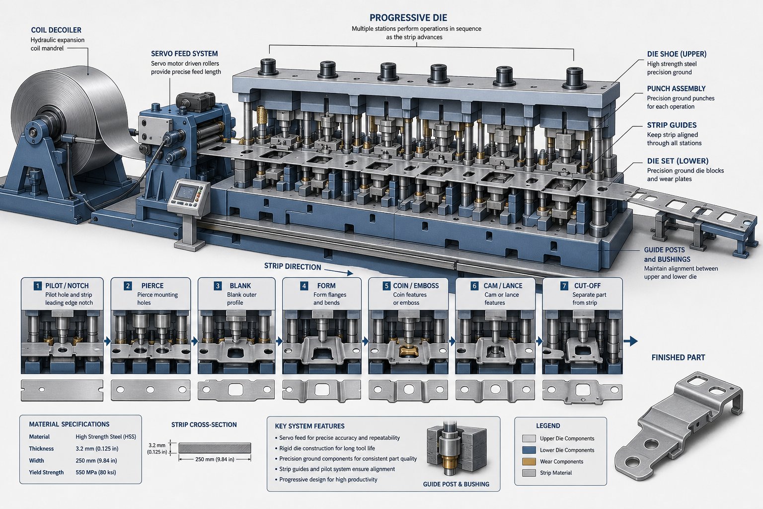
Progressive metal stamping ties all forming stations together on a single die set, with each part remaining connected to the original strip via a carrier until the final cutoff station. For large parts, this creates a cascade of challenges that smaller work never encounters.
The first problem is pitch. Pitch is the distance the strip must advance between each press stroke, and it corresponds directly to the part's length in the feed direction. A part that measures 30 inches in the feed direction needs at least 30 inches of pitch, plus whatever carrier material bridges between stations. Multiply that by eight or ten forming stations, and you're looking at a die that spans 20 feet or more. As The Fabricator's die basics series notes, progressive dies require all necessary stations mounted on a single common die set, timed and sequenced for a constant feed distance. At large scale, that single die set becomes an enormous, precision-ground tool.
Strip feeding introduces another layer of difficulty. Heavier coil stock, often 36 to 60 inches wide, requires servo feed systems with higher pulling force and longer stroke capacity. Coil weight climbs quickly. A 48-inch-wide coil of 4mm steel at a standard outer diameter can easily exceed 10,000 pounds, demanding heavy-duty uncoilers, powered straighteners, and feed lines engineered for that mass. Feed accuracy over long production runs degrades as coil diameter decreases and strip tension changes, so the feed system needs real-time compensation to hold pitch tolerance across thousands of cycles.
Registration is the third critical factor. Progressive dies for large parts use pilot pins inserted into pre-pierced holes to lock strip position at each station. But wider strips are more prone to lateral drift, edge wave, and camber. If the strip drifts even a few thousandths across a 40-inch width, the cumulative effect on feature location at downstream stations can push parts out of tolerance. Larger pilots, tighter bushing fits, and additional side-guide mechanisms become necessary.
The result? Progressive die stamping services for large components require not just bigger presses but a complete feeding and guidance ecosystem scaled to match.
Transfer and Tandem Line Alternatives
When a part's geometry grows too large to remain attached to a carrier strip, or when the forming sequence requires the part to be rotated or flipped between operations, transfer die stamping becomes the practical path forward.
Transfer systems decouple the part from any strip material. Individual blanks are destacked, fed into the first station, and then mechanically transferred from die to die using rails equipped with gripping fingers. According to Metal Forming Magazine, transfer presses typically feature straight-sided frames with at least two connecting rods, tonnage capacity from 300 to over 3,000 tons, and bolsters exceeding 275 inches in length to accommodate all stations.
Two-axis transfer systems slide parts forward from station to station. Three-axis systems add a vertical lift, picking parts up and placing them precisely within perimeter gauging boundaries. That third axis is critical for deep-drawn large parts, shells, and components that require repositioning between operations. As Standard Die International explains, transfer die stamping allows parts to be manipulated at various angles in a free state, enabling operations like cutouts, ribs, and threading that progressive dies simply can't achieve on large geometries.
Tandem press lines take this modularity further. Instead of multiple stations under one slide, a tandem line uses a separate press for each die operation, typically four to six presses arranged in sequence. The lead press handles the primary draw, while follower presses perform trimming, piercing, bending, and restrike operations. This configuration suits parts too large or too geometrically complex for even a transfer press to handle in a single frame.
Tandem lines represent the upper boundary of progressive die metal stamping services for oversized automotive panels and structural components. The largest installations feature bolster dimensions of 4,500 by 2,500 mm or greater, with lead presses exceeding 2,000 tons. Stroke rates range from 6 strokes per minute on standard mechanical drives up to 18 or more strokes per minute using servomechanical presses in continuous operation mode.
Some facilities run combined press lines that can operate as a standard progressive press at high speed, as a transfer press at slower speeds, or as a hybrid: progressive for the first several stations, then shearing parts from the strip and transferring them to subsequent die stations. This flexibility matters when a single facility needs to produce a mix of large-part geometries without dedicating separate lines to each.
Here's how the four primary approaches compare for large-format work:
| Method | Max Part Size Range | Ideal Geometry Types | Production Speed | Tooling Complexity |
|---|---|---|---|---|
| Progressive Die | Up to ~36 in. (limited by strip width and press bed) | Flat or shallow-formed parts with features in one plane | High (up to 1,500 strokes/min for smaller parts; 7-30 for large) | High - all stations on one die set |
| Transfer Die | Up to ~60+ in. (limited by bolster length) | Deep draws, shells, axially symmetric parts, multi-angle forming | Moderate (6-18 strokes/min) | Moderate - individual station dies plus transfer mechanism |
| Compound Die | Up to ~24 in. (single-stroke limitation) | Flat blanks requiring simultaneous cut and form in one stroke | High (single stroke completes part) | Low to moderate - one die, one operation set |
| Tandem Line | 60+ in. (separate press per operation) | Large automotive panels, deep structural components, complex multi-operation parts | Low to moderate (6-18 strokes/min) | Low per die, high system-level (4-6 presses coordinated) |
The choice between these methods isn't purely technical. Production volume, part complexity, and available press capacity all weigh in. A progressive approach might be physically feasible for a given large part, but if it requires a 2,400-ton press with a 240-inch bed that your supplier doesn't have, the transfer or tandem alternative becomes the real-world answer.
That intersection of physical feasibility and practical constraint is exactly where process selection decisions get made, and where choosing the wrong path costs months of tooling lead time and hundreds of thousands in sunk capital.
Selecting the Right Die Stamping Method by Part Size
Knowing what each process can do is only half the problem. The harder question: which one should you actually use for your specific part? When you're evaluating a die stamping service for large parts, the selection logic isn't a simple flowchart. It's a sequential elimination process where physics vetoes options before economics ever gets a vote.
Process Selection Criteria for Oversized Stampings
Start with the part itself. Its footprint relative to available press bed area is the first gate. If the part's projected area (including the carrier strip margins for progressive work) exceeds what the press bed can accommodate, that method is off the table. No amount of clever die design changes this constraint.
Draw depth is the next filter. Shallow forms under 25% of the blank diameter can often remain on a carrier strip in a progressive die. Deep draws, anything approaching a 1:1 depth-to-diameter ratio, typically require the blank to move freely. That means transfer stamping. Complex flanges with multi-axis bends compound this. Each additional forming axis adds a station, increases pitch, and demands more precise blank positioning between operations.
Tolerance stack-up behaves differently at large scale. In precision die stamping for compact parts, holding +/-0.05mm across a 4-inch dimension is routine. Scale that same tolerance requirement to a 30-inch dimension on an oversized stamping, and you're fighting thermal expansion of the die, elastic deflection of the press frame, and strip registration drift simultaneously. High precision metal stamping at large format demands not just better tooling but stiffer presses, temperature-controlled environments, and real-time monitoring.
Geometry constraints interact with size in ways that eliminate options rapidly. A part with undercuts requires cam-actuated side actions. On a 40-inch part, those cam units become massive, adding weight and complexity to an already oversized die. A part needing both a deep draw and precision-pierced features in the drawn wall may require the draw to happen on a transfer line and the piercing to happen in a secondary precision die and stamping operation. These aren't theoretical edge cases. They're common scenarios in large structural components.
Matching Volume Requirements to Process Economics
Physical feasibility narrows your options. Volume determines which surviving option makes financial sense.
Progressive dies favor high volume because their tooling cost is enormous but their cycle time is fast. For large parts, though, the press tonnage required pushes capital costs even higher. You might need a 1,200-ton press running progressive precision metal stampings for a structural bracket. If your annual volume is only 50,000 pieces, the amortization math may never work. Transfer dies, with their lower per-station tooling cost and ability to run on existing equipment, can be more practical for medium volumes of large components, even if the per-piece cycle time is slower.
High-precision stamping at scale creates a tension: tighter tolerances require more forming stations, which increases die length and press requirements, which increases cost, which raises the break-even volume. Engineers need to honestly assess whether every tolerance on the print is functionally necessary, or whether some dimensions can be relaxed to open up more economical process paths.
Process selection for large parts is driven first by physical feasibility: can the part be made this way? Only after that question is answered does economics enter the conversation: should it be made this way at this volume?
Here's the sequential evaluation every engineer should follow when selecting a process for oversized stampings:
- Map the part footprint against available press bed dimensions, including strip margins for progressive approaches
- Assess draw depth and determine whether the part can remain attached to a carrier strip throughout forming
- Count the number of required forming, piercing, and trimming operations to estimate station count
- Evaluate tolerance requirements relative to part size, identifying features that demand high-precision stamping versus those with relaxed limits
- Identify geometry constraints (undercuts, multi-axis bends, side actions) that eliminate specific process types
- Calculate tonnage requirements based on material, thickness, and total cut/form perimeter
- Compare surviving feasible methods against projected annual volume and target piece price
- Factor in secondary operations, whether post-stamping processes like machining or welding offset the need for a more complex die
By the time you reach step seven, physics has already done most of the deciding. The remaining choice between feasible methods is where production volume, tooling budget, and timeline constraints determine the final path forward. And that final path directly shapes how material will behave under forming pressure across the full scale of your part.
Material Behavior and Selection for Large-Scale Stampings
A 6-inch bracket cut from mild steel doesn't care much about grain direction. A 40-inch structural panel cut from the same coil? It cares intensely. Material behavior that's negligible at small scale becomes the dominant failure mode when part dimensions stretch across two or three feet of rolled metal. The same alloy, the same thickness, the same supplier, but the physics change because distance amplifies every anisotropic quirk the rolling mill baked into that sheet.
This is where most discussions about die stamping services for large parts fall silent. Suppliers list materials they can run. They rarely explain why those materials behave differently at scale, or how the wrong grade selection cascades into scrap rates that destroy your production economics.
Grain Direction and Edge Quality on Oversized Blanks
Every coil of sheet metal carries a directional fingerprint from the rolling process. As The Fabricator explains, rolling introduces bulk plastic deformation that elongates and rotates crystal grains, creating anisotropy: mechanical properties that vary based on the direction you measure them. The r-value, a ratio of width strain to thickness strain measured during tensile testing, quantifies this directional behavior. When r-values differ significantly between the rolling direction, the transverse direction, and 45 degrees to rolling, the material will thin, wrinkle, and spring back differently depending on how your blank is oriented relative to the coil.
On a small part, you might never notice. On a large blank, anisotropy becomes unavoidable. Consider a 36-inch shear cut running perpendicular to the rolling direction. Along that entire edge, the material's crystalline structure presents a consistent orientation to the shearing action. The edge quality, meaning the ratio of clean shear zone to fracture zone and burr height, remains relatively uniform. Rotate that same cut 90 degrees, and you're shearing along the grain. The edge character changes. Burr height increases, rollover depth shifts, and the fracture zone roughens. On extended shear lines typical of large-part blanking, these differences compound into measurable quality variations from one end of the cut to the other, especially on cuts that arc across multiple grain orientations.
Formability across large surfaces is where anisotropy hits hardest. In steel progressive stamping operations running wide strip stock, the forming stations must accommodate material that flows more easily in one direction than another. A draw operation spanning 30 inches will thin unevenly across its surface if the blank's r-value profile isn't accounted for in die geometry. The result: localized thinning in some zones, wrinkling in others, and an inconsistent wall thickness that fails inspection.
Flatness control during blanking adds another challenge. Large sheets are prone to residual stress patterns from coil set, crossbow, and edge wave. When you shear a large blank free from the strip, those internal stresses redistribute. A 48-inch blank may exhibit 0.030 inches or more of bow that wasn't visible while the material was constrained in coil form. For aluminum progressive stamping, this problem intensifies because aluminum's lower elastic modulus means residual stresses create proportionally more distortion. Leveling before blanking helps, but the leveler must be sized for the strip width, and over-leveling can introduce work hardening that reduces formability downstream.
Material Grade Selection for Large-Part Stamping
Choosing the right alloy for a large stamped component isn't just about strength and cost. It's about how that material will behave across a forming surface measured in feet, not inches. Each material family presents distinct trade-offs at scale.
Carbon steel progressive stamping covers the broadest range of large-part applications. Mild steels like 1008 and 1010 offer excellent formability and predictable behavior across large draws. HSLA grades (340, 420, 550 MPa classes) provide weight savings through thickness reduction but exhibit significantly more springback. Dual-phase steels (DP590, DP780) combine high strength with reasonable elongation, but their work-hardening behavior makes them unpredictable on long forming passes. The higher the strength grade, the more aggressively springback must be compensated in the die design.
Aluminum alloys present a different problem set. The 5000 series, particularly stamping-grade 5754 and the widely used 5052, provides good formability and corrosion resistance for structural panels. However, aluminum's tendency toward Luders band formation (visible stretcher strain marks) on large draw surfaces requires careful blank holder pressure tuning. The 6000 series alloys like 6061 offer higher strength but require solution heat treatment and age hardening, complicating the production sequence. Aluminum progressive stamping for large parts demands tighter die clearances than steel because aluminum galls more readily against tooling surfaces, and that galling tendency increases with contact area.
Stainless steels bring high work-hardening rates to the equation. Austenitic grades like 304 and 316 harden rapidly during forming, meaning the force required to complete the final forming station can be dramatically higher than the first. In stainless steel progressive stamping for large components, this progressive hardening means tonnage calculations must account for the cumulative work hardening across all stations, not just the instantaneous force at any single station. Ferritic stainless grades (409, 430) offer lower work hardening and better formability for applications where corrosion resistance matters but extreme ductility is less critical.
Copper progressive stamping and brass progressive stamping occupy a narrower niche in large-part work, typically limited to electrical bus bars, heat exchanger plates, and RF shielding enclosures where conductivity or thermal properties drive the material choice despite higher cost.
| Material Family | Typical Thickness Range (Large Parts) | Formability Rating | Springback Severity | Common Large-Part Applications |
|---|---|---|---|---|
| Mild Steel (1008/1010) | 1.0 - 6.0 mm | Excellent | Low | Structural brackets, chassis components, enclosures |
| HSLA Steel (340-550 MPa) | 1.2 - 5.0 mm | Good | Moderate to High | Automotive frame rails, cross members, reinforcements |
| Dual-Phase Steel (DP590-DP780) | 1.0 - 3.5 mm | Moderate | High | Crash-critical automotive structures, B-pillars |
| Aluminum 5052/5754 | 1.0 - 4.0 mm | Good | Moderate | Body panels, heat shields, marine components |
| Aluminum 6061 | 1.5 - 6.0 mm | Moderate | Moderate to High | Structural frames, aerospace brackets (post-heat-treated) |
| Stainless 304/316 | 0.8 - 4.0 mm | Good (but high work hardening) | High | Food equipment panels, architectural cladding, medical housings |
| Stainless 409/430 (Ferritic) | 1.0 - 3.0 mm | Good | Moderate | Exhaust components, appliance panels |
| Copper / Brass | 0.5 - 3.0 mm | Excellent | Low to Moderate | Bus bars, heat exchangers, RF shielding |
Springback compensation is where material selection and part size collide most painfully. On a small part, you overbend by a few degrees and call it done. On a 30-inch flange formed from DP780 steel, the springback magnitude can exceed 8 to 12 degrees, and it varies across the length of the bend based on local thickness variation, friction, and temperature. Compensating for this requires die geometry that intentionally over-forms the part, then relies on elastic recovery to bring it back to nominal. The longer the bend line, the more points along that line where springback behavior diverges from prediction. Higher-strength materials amplify this nonlinearity, and larger parts give that amplification more room to express itself.
This is precisely where finite element analysis (FEA) becomes non-negotiable. As Keysight's analysis of sheet metal forming simulation explains, FEA-based virtual die tryouts can predict springback, wrinkles, thinning, and splits before any physical tooling is built. The simulation captures the interaction between material properties, tool geometry, and process parameters like blank holder force and lubrication. For large-format dies costing tens or hundreds of thousands of dollars, catching a thinning failure or wrinkling defect virtually saves months of rework.
Simulation accuracy depends on inputting correct material data. Generic handbook values won't cut it for large-part work. You need actual tensile test data from the specific coil lot, including r-values at 0, 45, and 90 degrees to rolling direction. The more material data you feed the FEA model, the more reliably it predicts what happens when that 42-inch blank hits the draw punch and metal begins flowing across a surface area large enough to expose every hidden inconsistency in the sheet.
Material behavior at scale isn't a secondary consideration. It's the variable that determines whether your die produces parts or scrap. And the forces required to push that material into shape, across the full geometry of an oversized component, define what press capacity you actually need.
Press Capacity and Tonnage Scaling for Big Components
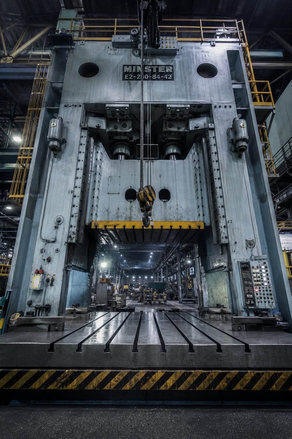
Material behavior tells you what forces the metal will resist. Press capacity tells you whether your equipment can deliver those forces across the full geometry of an oversized component. These two realities collide at the press frame, and when they don't align, large-part die stamping simply doesn't happen. No amount of clever die design compensates for a press that lacks the tonnage, bed area, or shut height to execute the forming sequence.
This is the constraint that kills projects silently. Engineers design a part, select a material, plan the forming sequence, and then discover the progressive stamping machine required doesn't exist in their supplier's facility. Understanding how tonnage scales with part size, and how bed dimensions and shut height interact with die geometry, separates feasible projects from expensive false starts.
Press Tonnage Requirements for Large-Format Stamping
Tonnage in heavy stamping scales through two distinct mechanisms depending on the operation type. Blanking and piercing operations scale with perimeter. Forming and drawing operations scale with surface area. Both multiply with material thickness. When a part is large enough to involve significant amounts of all three operation types, the total tonnage demand climbs fast.
For blanking and piercing, the fundamental calculation is straightforward: the cut perimeter (in inches) multiplied by the material thickness (in inches) multiplied by the material's shear strength (in tons per square inch). As The Fabricator's tonnage calculation guide details, this formula uses full material thickness to compensate for dull and worn tooling, since actual shearing occurs partway through the stock. On a large part with 200 inches of total cut perimeter in 4mm mild steel, the blanking tonnage alone can exceed 150 tons before you account for any forming.
Drawing operations use a similar perimeter-based calculation but substitute ultimate tensile strength for shear strength, because the shell walls are in tension during the draw. For a large draw spanning 30 or more inches in diameter, the drawing force can rival or exceed the blanking tonnage, particularly in higher-strength progressive stamping materials like HSLA or dual-phase steels.
But these raw calculations only capture part of the picture. A progressive die for a large component doesn't perform one operation per stroke. It performs all of them simultaneously. Every station in the die demands force at the same instant the press reaches bottom dead center. You need to sum the loads from every piercing punch, every forming station, every spring stripper, every nitrogen pressure pad, every driven cam, and every scrap cutter. For a 12-station progressive die running heavy gauge stock, the cumulative load can easily reach 800 to 1,200 tons.
Material thickness is the multiplier that makes large-part tonnage particularly brutal. Doubling the thickness doesn't just double the force. It doubles the force at every station simultaneously. A part that requires 400 tons in 2mm steel demands approximately 800 tons in 4mm steel, assuming identical geometry. Combine that thickness increase with the longer cut perimeters inherent to large parts, and you see why heavy stamping operations routinely require presses in the 600 to 2,000+ ton range.
Engineers calculating required press capacity should also account for the energy requirement, not just the force. A press can have sufficient tonnage rating but insufficient flywheel energy to sustain that force through the working portion of the stroke. Insufficient energy causes the press to stall at bottom dead center, a common failure mode when running large progressive dies at speeds that outpace the motor's ability to re-energize the flywheel between strokes.
Bed Size and Shut Height Constraints
Tonnage gets the attention, but bed size and shut height quietly eliminate more projects than force capacity ever does. A 1,000-ton press is useless for your large part if its bed measures 60 by 40 inches and your die requires 96 by 48.
Press bed dimensions define the maximum die footprint. For progressive dies serving large parts, the bed must accommodate not just the part's width and length, but the full die set including all stations, scrap chutes, pilot mechanisms, and strip guides. A 10-station progressive die for a 30-inch-wide part can easily span 120 inches in the feed direction. The press bed must support that length while also providing bolt-down area in the T-slot pattern for secure clamping.
Shut height is the distance from the bottom face of the ram to the top of the press bed with the ram at bottom dead center and adjustment set full-up. As MetalForming Magazine explains, this dimension is distinct from die height, which subtracts the bolster plate thickness. The die's shut height (its fully closed overall dimension) must fall within the minimum and maximum die-height space. If it doesn't fit, the die either can't close fully or it bottoms out before the ram completes its stroke, generating catastrophic overload forces that damage both the die and the press frame.
For large-part dies, shut height becomes particularly constrained. Complex forming sequences require tall die assemblies with deep draw cavities, multiple pressure pads stacked vertically, and thick die shoes that resist deflection. A large transfer die might need 24 to 36 inches of shut height just to accommodate the forming geometry, pressure systems, and structural shoe thickness. The press must provide that vertical space while also delivering sufficient stroke length for the deepest draw in the sequence.
Bolster plate capacity imposes a weight limit that's easy to overlook. Large-format progressive dies can weigh 5 to 15 tons or more. The bolster must support that static load uniformly without deflecting beyond the press manufacturer's specifications. The press tonnage rating and deflection specifications assume the die load is equally distributed over two-thirds of the bed area. A narrow die that concentrates load in the center of an oversized bed, or a long die that loads only one end of the bolster, creates uneven deflection that degrades part quality and accelerates wear.
Die change logistics also escalate with size. Dies weighing several tons require overhead crane access, rolling bolster systems, or dedicated die carts for changeover. Quick die change systems designed for 500-pound dies don't scale to multi-ton tooling. Facilities running large-part stamping need crane capacity rated for their heaviest die, plus clearance between the press uprights for side-loading or front-loading the tool.
When evaluating whether a die stamping service for large parts can actually produce your component, these are the press specifications that matter:
- Bed area - Total available bolster surface in both axes, confirming the die footprint fits with margin for clamping
- Shut height - Maximum and minimum die-height space (press shut height minus bolster thickness, with ram adjustment range), ensuring the die assembly fits in its closed position
- Tonnage - Rated capacity at the point in the stroke where peak load occurs, not just the nameplate number
- Slide stroke - Total ram travel, which must exceed the deepest draw depth plus clearance for part extraction and transfer motion
- Feed line height - The centerline height of the strip feed relative to the bolster top, which must match the die's pass-line for proper material entry
- Bolster T-slot pattern - Slot spacing, width, and depth that must accommodate the die's clamping scheme and match the die shoe's bolt pattern
Reputable suppliers publishing detailed equipment lists, sometimes itemizing dozens of presses by tonnage, bed size, and stroke, provide a tangible credibility signal. You can cross-reference your part's requirements against their published capabilities before the first conversation happens.
Press capacity determines what's physically possible. But the die that sits inside that press, the tool that actually shapes metal, introduces its own set of design challenges that compound with part size. How those dies are engineered for rigidity, guidance, and maintainability at large scale is a discipline unto itself.
Die Design Considerations Specific to Large Parts
A press with enough tonnage and bed area only sets the stage. The die itself, the precision tool that actually contacts metal and forces it into shape, carries an entirely different set of engineering demands when scaled to large-part dimensions. On a compact die for a 6-inch bracket, minor deflections in the shoe go unnoticed. On a die spanning 60 or 80 inches, that same proportional deflection translates to thousandths of an inch of misalignment across the forming surface. Punches miss their mating cavities. Formed features drift out of tolerance. Shear edges wear unevenly. The die doesn't just get bigger. Every structural, guidance, and pressure system within it must be re-engineered to maintain precision across a span that actively fights rigidity.
This is the domain where progressive die manufacturers separate themselves from general stamping shops. Anyone can build a small die that works. Building a large die that holds tolerance across millions of cycles requires structural engineering discipline that's closer to bridge design than watchmaking.
Structural and Guide System Design for Large Dies
The die shoe is the foundation. On small dies, a standard pre-hardened die shoe from catalog stock does the job. On large-format tooling, the shoe must be custom-engineered for stiffness. Imagine a die shoe spanning 90 inches in the feed direction. Under full tonnage at bottom dead center, that shoe wants to bow upward in the center between the press bolster supports. If it deflects even 0.002 inches at center span, the cutting clearances across the middle stations shift, edge quality degrades, and punch life drops.
Large die shoes are typically machined from stress-relieved plate (S50C or equivalent medium carbon steel) at thickness ranging from 4 to 8 inches, depending on span and load. As Ming Chiang's die design guide explains, die set material selection follows a "right material for the right place" principle: the shoe acts as a shock-absorbing foundation, using toughness to absorb vibration and protect precision components from direct impact damage. At large scale, this shock absorption role becomes critical because impact energy is proportionally higher and resonant vibration modes emerge at lower frequencies.
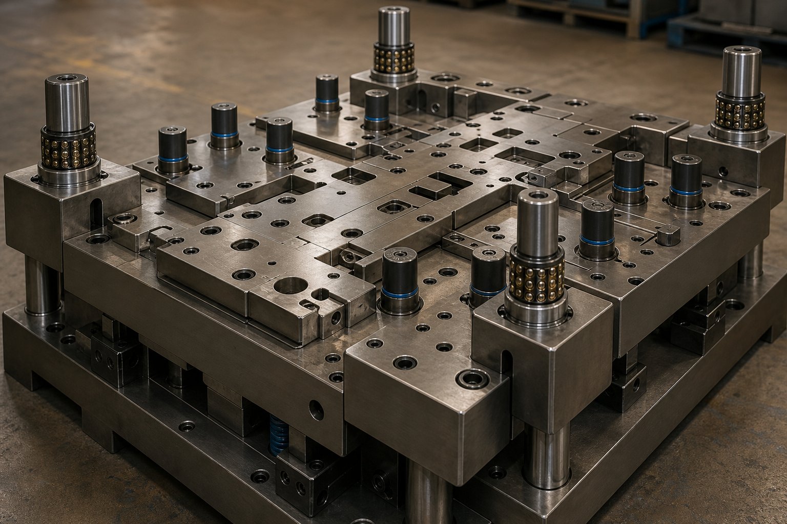
Guide systems scale up in both size and configuration. A standard two-post die set provides adequate alignment for compact tooling. Large-format dies and stamping assemblies demand four-post or center-guided configurations to prevent angular rotation of the upper shoe during off-center loading. Four corner guide posts distribute alignment forces across all four quadrants of the die, preventing the racking that occurs when forming loads concentrate at one end of a long die.
The guide posts themselves increase in diameter, often reaching 2 to 4 inches, and use precision ball-bearing cages rather than plain bronze bushings to reduce friction and maintain alignment accuracy under heavy side loads. Some large progressive die manufacturers specify an inner guide post system in addition to the outer guide posts, creating a dual-guidance architecture. The outer posts handle coarse alignment during initial closure, while inner posts provide micron-level precision at the final forming position. This dual-guide approach is particularly valuable for progressive machine die sets where station-to-station alignment must remain consistent across the full die length.
Nitrogen spring systems present a unique scaling challenge. On a small die, a single nitrogen cylinder provides uniform blank holder or stripper pressure. On a large die with a pressure pad spanning 40 inches, you might need 8, 12, or even 20 nitrogen cylinders arranged in a calculated pattern to distribute force evenly across the pad surface. If the cylinders aren't positioned correctly, the pressure pad tilts under load, creating uneven material flow during drawing or inconsistent stripping force that leaves slugs stuck in the die.
Designing the nitrogen spring layout requires mapping the force distribution needed across the pressure pad surface, then selecting cylinder bore sizes and locations that deliver that distribution within acceptable uniformity, typically within 5-10% variation across the pad face. The preload and stroke of each cylinder must account for differential deflection of the mounting plate. Taller dies with longer strokes may require manifold-connected systems that equalize pressure across all cylinders hydraulically, ensuring uniform pad travel regardless of uneven loading.
Pilot pin strategy for large-format dies follows a different logic than compact tooling. In standard progressive dies, two or three pilots adequately register the strip at each station. On a wide strip feeding through a large die, lateral strip drift and edge wave mean the material's position is less predictable across its full width. Talan Products' engineering guidance notes that pilots enter holes pierced in early stations and that when these holes require tight tolerances, separate pilot holes on the carrier maintain accuracy without elongating functional features. For large dies, engineers often add supplemental edge-guide pilots or spring-loaded centering mechanisms at intermediate stations to prevent cumulative drift from corrupting downstream feature locations. The wider the strip, the more pilot points are necessary to constrain the material's natural tendency to wander.
Custom Die Engineering for Complex Large Geometries
Beyond structural rigidity and guidance, the working components of a large die, the punches, lifters, strippers, and forming inserts, all require design approaches that differ fundamentally from small-tool practice.
Lifters on large progressive dies must raise a heavy strip high enough to clear formed features as it advances to the next station. On a narrow strip, lightweight pin lifters do the job. On a 48-inch-wide strip of 3mm steel, the strip weight between lifter points can cause sagging that buckles the carrier or drags on die surfaces. Bar lifters spanning the full strip width, or rail-style lifter systems, provide the distributed support needed. Talan Products' design methodology emphasizes that sagging between lifters can buckle carriers, especially with thin materials. At large scale, even thick materials sag under their own weight across wide unsupported spans.
Bypass notches are critical for scrap management on large dies. When a blanking or trimming operation generates a slug wider than the strip can carry past downstream stations, that scrap must be redirected, either dropped through the die immediately or notched to allow clearance past subsequent punches and forming stations. On a compact die, scrap management is an afterthought. On a large progressive die where slugs may be 8 to 12 inches wide, a jammed slug can crash the die, bending punches and damaging forming surfaces. Proper bypass notch geometry, scrap chutes angled for gravity assist, and air-blast slug ejection become essential design features.
Burr direction control on long shear edges requires careful planning. Every cutting operation produces a burr on one side of the material. On a 36-inch trim line, the burr direction determines which surface of the finished part carries that raised edge. For progressive die stamped brackets and structural components that interface with other assemblies, burr location is a functional requirement, not cosmetic. The die designer must orient cutting clearances so burrs appear on the acceptable face, which may require splitting long cuts into segments with opposing clearance directions or adding secondary shaving stations to remove burrs entirely.
Clearance optimization for forming operations on large surfaces introduces a scale effect. Die clearance, the gap between punch and cavity, controls material flow during drawing and forming. On a small draw, uniform clearance around the perimeter works fine. On a large draw spanning 30 or more inches, material flows at different rates from different directions due to grain orientation and friction variation. Variable clearance, tighter in areas where material tends to thin and looser where wrinkling threatens, helps control material distribution. This variable clearance mapping typically comes from FEA simulation and is refined during die tryout.
Maintenance access drives another design decision unique to large tooling: component segmentation. A one-piece stripper plate spanning 80 inches would be impossible to grind flat, difficult to heat-treat uniformly, and impractical to remove for maintenance. Instead, large die strippers, punch retainer plates, and even die cutting inserts are segmented into sections that can be individually removed, reground, or replaced without disassembling the entire die. Segmentation also allows the use of different materials for different zones, matching component material to the local wear severity. As die design best practices indicate, core punches and inserts utilize high-speed steel (SKH9) at HRC 60-62 for extreme wear resistance, while structural plates use cold work tool steel (SKD11) at HRC 58-60. On a large segmented die, high-wear zones get premium insert material while lower-stress areas use less expensive grades, optimizing cost without sacrificing durability where it matters.
For tooling engineers navigating these design-intensive decisions, working with specialists who understand the interplay between die structure, component engineering, and material flow at large scale is critical. YICHEN's custom stamping die solutions address this intersection directly, connecting engineers to die design expertise covering everything from punch and lifter configuration to bypass notch strategy, burr control, and clearance optimization for large-format applications. When the tooling challenge involves managing complexity across a die that weighs several tons and spans six feet or more, having a technical partner with deep die engineering experience shortens the path from concept to production-ready tooling.
Here are the critical die design elements that require special attention at large scale:
- Die shoe rigidity - Custom-thickness shoes engineered for minimum deflection at center span under full forming load
- Guide post configuration - Four-post or dual-guide systems (outer plus inner) to prevent racking and maintain station-to-station alignment
- Nitrogen spring layout - Multi-cylinder patterns calculated for uniform pressure distribution across large pads, with manifold equalization where needed
- Pilot strategy - Increased pilot density across wide strips, including supplemental edge guides and intermediate registration points
- Lifter system design - Bar or rail-type lifters that prevent strip sag across wide unsupported spans
- Bypass notch geometry and scrap management - Engineered slug clearance paths with gravity-assisted chutes and air-blast ejection for large slugs
- Burr direction planning - Clearance orientation mapped to functional burr-side requirements across all long shear edges
- Variable forming clearance - FEA-driven clearance maps that account for anisotropic material flow across large draw surfaces
- Component segmentation - Strippers, retainers, and cutting inserts divided into maintainable sections with zone-specific material grades
- Thermal management - Consideration of heat buildup in large dies during high-speed operation, including cooling channels or thermal breaks in high-friction zones
Each of these elements interacts with the others. A poorly planned nitrogen spring layout creates uneven stripping force, which accelerates wear on guide posts, which degrades punch-to-cavity alignment, which shifts burr patterns unpredictably. In large-format dies, these cascading interactions amplify across distance, making integrated design thinking, rather than component-by-component specification, the difference between a die that runs reliably and one that demands constant intervention.
Getting the die design right protects a significant capital investment. And that investment, the tooling cost itself, raises its own set of questions about economics, amortization, and where large-part die stamping actually makes financial sense versus alternative fabrication approaches.
Cost Economics and Tooling Amortization for Large Parts
A well-designed die solves the engineering problem. But engineering feasibility and financial viability are two separate conversations. Large-part progressive and transfer dies represent some of the most significant capital commitments in metal manufacturing, and the economics behave differently than what engineers familiar with compact tooling might expect. The upfront investment is larger. The amortization curve is steeper. And the maintenance burden over a die's lifetime introduces costs that smaller tooling rarely imposes.
Yet no supplier in this space lays out the economic logic transparently. You'll find equipment lists and capability brochures, but rarely the financial framework that tells you whether your specific part, at your specific volume, justifies the tooling investment at all. That's the gap this section fills.
Tooling Investment and Amortization for Large Dies
Die cost scales with three primary drivers: the number of forming stations, the physical size of the die, and the precision requirements of the finished part. For standard progressive dies producing small to mid-sized components, industry data from Shaoyi Metal Technology places typical tooling in the $15,000 to $60,000 range. But large-part dies operate in a different tier entirely. Transfer and line dies for oversized automotive panels routinely reach $250,000 to over $1,000,000 when the full die set includes draw, trim, flange, and pierce operations.
Why the dramatic jump? Every cost driver compounds at large scale. More stations means more machining hours. Larger die shoes require heavier raw steel billets and longer CNC cycle times. Wider cutting and forming inserts demand premium tool steels in larger volumes. The tryout phase, where the die is tested and adjusted in an actual press, takes longer because large dies are physically harder to load, shim, and iterate on. Tryout and validation alone typically represents 10-15% of total die cost, and on a six-figure tool, that's a substantial line item.
Die material accounts for 20-40% of the total investment. For high-volume metal stamping programs expecting 500,000 or more hits over the die's lifetime, toolmakers specify premium grades like SKD11 or solid carbide inserts at critical wear points. These materials resist abrasion over millions of cycles but carry significant raw material cost, especially when cut into the oversized inserts that large-part tooling demands. For shorter production runs, less expensive alloys can reduce upfront cost, but they trade longevity for savings, requiring more frequent maintenance or earlier replacement.
Amortization is where the math either works or doesn't. A $50,000 progressive die spread across 500,000 parts adds just $0.10 per piece in tooling cost. That same die spread across only 5,000 parts adds $10.00 per piece, as Fictiv's progressive stamping analysis illustrates. For large-part dies costing several times that amount, the break-even threshold shifts dramatically upward. A $300,000 transfer die set needs substantial annual volumes before the per-piece tooling contribution drops to a level that competes with alternative fabrication methods.
Minimum order quantities exist precisely because of this amortization reality. OEM progressive stamping programs typically commit to annual volumes that ensure the tooling investment pays back within one to three production years. If your forecasted volume can't absorb the tooling cost within a reasonable payback window, the project either needs a simpler die approach, a shared-tooling arrangement, or a fundamentally different manufacturing method.
Per-Piece Economics at Scale
Once the tooling is paid for, the per-piece economics of die stamping become remarkably compelling. Talan Products' cost analysis demonstrates that a progressive die press can produce 4,000 or more parts per hour, with labor costs measured in fractions of a cent per piece. After tooling payoff, the per-piece cost drops to the bare minimum: raw material, machine time, and a sliver of labor. At those economics, long run metal stamping dominates any fabrication alternative on a per-unit basis.
But large-part dies introduce a complication that smaller tooling avoids: maintenance cost as a meaningful percentage of lifecycle economics. Industry estimates place annual die maintenance at 5-10% of the die's original value, depending on usage intensity. On a $30,000 compact die, that's $1,500 to $3,000 per year. On a $250,000 large-format transfer die, that's $12,500 to $25,000 annually in sharpening, shimming, spring replacement, and insert regrinding. Neglecting this maintenance doesn't save money. It leads to burrs on parts, accelerated wear, and eventual catastrophic die failure that costs far more than preventive care.
Total lifecycle cost for large run stampings must account for four distinct cost buckets:
- Initial tooling investment - The one-time capital outlay for die design, fabrication, and tryout
- Per-piece production cost - Material, press time, labor, and overhead allocated per part during active runs
- Scheduled maintenance - Regular sharpening intervals, nitrogen spring replacement, guide bushing wear, and component inspection
- Die refurbishment - Major overhauls at extended intervals (typically every 500,000 to 2,000,000 cycles depending on material severity), including insert replacement, regrinding of forming surfaces, and structural inspection
For OEM metal stamping services running high-strength materials at large scale, maintenance intervals compress. Dual-phase steel and stainless grades wear cutting edges faster than mild steel, shortening the cycle count between sharpening events. A die that runs 200,000 hits between maintenance on 1008 steel might need attention every 80,000 hits on DP780. That accelerated maintenance schedule directly affects your effective per-piece cost, even after tooling is fully amortized.
The volume crossover point, where stamping becomes cheaper than fabrication, shifts depending on part complexity and material. For simple large geometries in mild steel, Talan's data suggests the crossover falls between 3,000 and 7,000 parts per year for standard-size components. For large parts requiring high-tonnage presses and complex multi-station dies, that crossover pushes considerably higher, often into the 10,000 to 25,000 annual unit range before the economics decisively favor stamping over laser cutting plus press brake forming.
Large-part die stamping becomes cost-effective only above certain volume thresholds, and those thresholds vary dramatically by part complexity, material grade, and die maintenance intensity. A simple mild steel bracket at 15,000 annual units justifies tooling easily. A complex HSLA structural component at the same volume may not break even for three years.
When building a business case for large-part die stamping versus alternative fabrication, engineers should model these cost factors explicitly:
- Total tooling investment including design, fabrication, tryout, and engineering changes during commissioning
- Projected annual volume and total lifetime volume over the program's expected duration
- Per-piece production cost at target cycle rates, including material yield losses from large-format strip layouts
- Annual maintenance cost based on material severity and expected hit count between service intervals
- Die refurbishment cost at major milestone intervals, including the production downtime during overhaul
- Comparison per-piece cost using alternative methods (laser plus forming, weldments, or castings) at the same volume
- Payback period: at what cumulative volume does the total stamping cost (tooling plus production plus maintenance) cross below the total alternative fabrication cost
- Risk factors including design change probability, volume forecast confidence, and material cost volatility
The payback calculation isn't just arithmetic. It requires honest volume forecasting. An optimistic projection that justifies the tooling investment but never materializes in actual orders leaves you holding a six-figure asset generating no return. Conservative forecasting protects capital, even if it means choosing a less optimal per-piece process for the first few years and transitioning to die stamping once volumes prove out.
Economics tell you whether to proceed. But they don't tell you when to walk away entirely. Some large parts, regardless of volume, face geometry constraints, material limitations, or tolerance demands that make die stamping the wrong answer, no matter how the numbers work on paper.
Process Limitations and When to Choose Alternatives
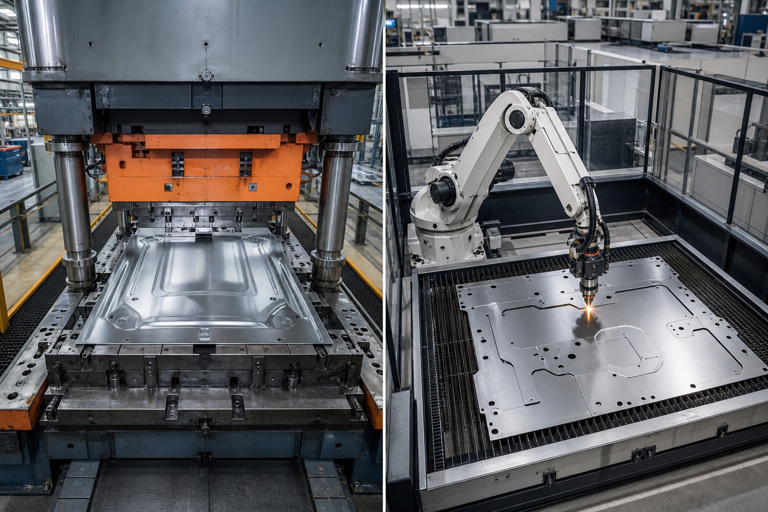
Every manufacturing process has a ceiling. Die stamping hits its ceiling when part geometry, material constraints, or volume realities push beyond what a die can physically or economically deliver. Most sheet metal stamping services won't volunteer this information. They'll quote what they can make, not what they shouldn't attempt. But honest process evaluation requires understanding where the boundary sits, because forcing a part through the wrong method costs more than choosing the right alternative from the start.
When Die Stamping Is Not the Right Answer
Maximum practical part size for die stamping tops out around 72 to 96 inches in the feed direction for progressive work and somewhat larger for tandem lines handling automotive outer panels. Beyond that, no standard press bed accommodates the tooling, and custom press installations become a project in themselves.
Geometry imposes harder limits than size. Parts with extreme draw ratios, anything approaching a depth-to-diameter ratio above 2:1, typically can't be drawn in a single operation without intermediate annealing. Undercuts, re-entrant features, and internal geometry that requires side access simply can't form in a vertical press stroke without cam-actuated mechanisms that add enormous complexity and cost. At large scale, those cam units become impractically massive.
Certain materials resist large-format stamping regardless of geometry. Work-hardening alloys like 300-series stainless become progressively harder to form across multiple stations, and the cumulative tonnage on a large die may exceed available press capacity. Thick plate above 8mm generally moves into press brake or hydraulic press territory rather than progressive stamping and fabrication approaches, because the forces required exceed what conventional stamping presses deliver efficiently.
Consider these scenarios where alternatives outperform die stamping:
- Low volume with complex geometry - Laser cutting plus press brake forming delivers finished parts without any tooling investment, ideal for runs under 3,000 units
- Tight tolerances on thick plate - CNC machining from plate stock holds tolerances that stamping can't match on heavy gauge material
- Complex 3D enclosures with internal features - Weldments from individually formed pieces allow undercuts, internal stiffeners, and features impossible in a single stamping operation
- Organic shapes with non-uniform wall sections - Castings handle geometries that no flat-blank forming sequence can replicate
Even in hvac progressive metal stamping, where large duct components and structural housings are common sheet metal stamping products, engineers routinely encounter parts that exceed practical stamping limits. An oversized plenum box with internal baffles and welded flanges, for example, might seem like a stamping candidate based on volume alone, but its geometry makes fabrication the faster and cheaper path.
Comparing Alternatives for Large-Format Metal Components
The decision isn't always binary. Hybrid approaches work well for large components where die stamping handles the high-volume repeatable operations (blanking, initial forming, piercing) while secondary processes complete features the die can't produce. A structural automotive bracket might be progressively stamped for its primary geometry, then robotically welded to add a gusset that would require an impractical cam mechanism in the die. These metal stamping solutions blend process strengths rather than forcing one method to do everything.
For parts with low-volume requirements, the tooling investment in die stamping simply can't amortize. As production cost analysis from Hotean demonstrates, laser cutting averages significantly lower per-unit cost than stamping for batches under 3,000 pieces once you factor in the $15,000+ tooling expense that stamping demands before producing a single part. That gap widens further with large-part tooling costing multiples of standard die prices.
Here's how the primary alternatives stack up against die stamping for large-format metal components:
| Method | Ideal Volume Range | Geometric Complexity | Tolerance Capability | Relative Per-Piece Cost (Low Vol.) | Relative Per-Piece Cost (High Vol.) |
|---|---|---|---|---|---|
| Die Stamping | 10,000+ annually | Moderate (limited by draw depth and single-axis forming) | +/-0.005 in. standard; +/-0.001 in. with fineblanking | Very High (tooling amortization dominates) | Very Low |
| Laser Cutting + Forming | 1 - 5,000 annually | High (any 2D profile, bends limited by brake tooling) | +/-0.004 in. cut; +/-0.010 in. formed | Low (no tooling) | High (labor-intensive per piece) |
| CNC Machining | 1 - 2,000 annually | Very High (any machinable geometry) | +/-0.001 in. or better | Moderate (material waste on large plate) | Very High (slow cycle time) |
| Weldments | 1 - 5,000 annually | Very High (internal features, multi-plane assemblies) | +/-0.015 in. typical; +/-0.005 in. with fixtures | Moderate (labor plus fixturing) | High (welding doesn't scale linearly) |
| Castings | 500 - 100,000+ annually | Extremely High (organic shapes, variable wall thickness) | +/-0.010 in. investment cast; +/-0.030 in. sand cast | Moderate (pattern cost lower than die cost) | Low to Moderate |
Notice the crossover. At low volumes, every alternative beats die stamping on total cost. At high volumes, die stamping beats everything on per-piece economics. The gray zone, roughly 3,000 to 15,000 annual units for large parts, is where the decision requires detailed modeling rather than rules of thumb. Geometry tips the balance: a simple flat bracket crosses into stamping territory at lower volumes than a complex deep-drawn shell.
Castings deserve special attention for large structural components. Investment casting and sand casting both handle geometries that stamping cannot replicate, and their tooling costs (patterns rather than hardened steel dies) are typically 30-60% lower than equivalent stamping dies. The trade-off is looser tolerances, longer lead times per piece, and secondary machining requirements for critical interfaces. For parts where weight optimization through variable wall thickness matters more than tight dimensional control, casting often wins regardless of volume.
The honest framing: die stamping is the right answer when volume is high, geometry is compatible with flat-blank forming, and tolerances align with what the process naturally delivers. When any of those conditions fails, alternatives aren't compromises. They're better engineering decisions. The key is recognizing which condition broke before committing capital to tooling that will underperform.
Knowing when to stamp and when to fabricate is half the supplier evaluation challenge. The other half is finding a partner with the equipment, tooling expertise, and engineering depth to execute whichever path makes sense for your specific large-format component.
Evaluating Die Stamping Service Providers for Large Work
Finding a supplier that can stamp your part is easy. Finding one that can stamp your large part reliably, at tolerance, across a multi-year production program, is a fundamentally different search. The capabilities that separate competent metal stamping suppliers from those equipped for oversized work aren't listed on every company's brochure. You have to know what to ask, what to verify, and what red flags signal a shop reaching beyond its actual capacity.
Key Capabilities to Verify in a Large-Part Stamping Supplier
Press tonnage range is the obvious starting point, but don't stop at the nameplate number. Ask where peak tonnage is available in the stroke. A 1,000-ton press rated at bottom dead center delivers that force only at BDC. If your forming operation peaks 2 inches above bottom, the available tonnage may be 15-20% lower depending on the press type. You need capacity matched to your actual load curve, not a catalog spec.
Maximum bed size matters equally. A custom metal stamping company claiming large-part capability but running presses with 48-inch beds can't accommodate the 80-inch progressive die your structural bracket requires. Confirm bed dimensions in both axes, and verify bolster load capacity for dies weighing several tons.
An in-house tool room separates serious progressive die stampings suppliers from shops that outsource every maintenance event. Large dies need regular sharpening, nitrogen spring service, and guide bushing replacement. If the supplier ships your 8-ton die offsite for every maintenance cycle, you're looking at weeks of downtime per event versus days with an internal tool room. As KMC Manufacturing's tooling approach demonstrates, integrated tool and die operations that handle design, build, and maintenance under one roof deliver faster turnaround and tighter control over tooling quality across the full program lifecycle.
Simulation and FEA capabilities indicate whether a supplier can predict problems before cutting steel. For large-format work, virtual die tryouts save tens of thousands in physical tryout iterations. Ask whether they run forming simulations in-house or rely on the die builder to handle it independently. The best metal stamping services near me, or anywhere, maintain simulation engineers who collaborate directly with press operators and die designers.
Secondary operation capacity often gets overlooked. Deburring a 36-inch stamping requires equipment scaled for that footprint. Dimensional inspection using coordinate measuring machines needs a measurement envelope large enough to capture the full part geometry. If the supplier outsources inspection to a third-party lab, turnaround times for first-article approval stretch from days into weeks. Even ancillary needs like labeling services for metal stamping become logistically complex when parts are oversized and require specialized fixturing for marking operations.
Logistics deserve scrutiny. Large stamped components create handling and shipping challenges that smaller parts never encounter. Packaging must prevent deformation during transit. Shipping oversized metal products involves specialized crating, load-specific securement methods, and potentially oversize freight permitting. Confirm that your supplier has the material handling equipment, staging space, and shipping partnerships to move your parts without damage.
Quality certifications provide a baseline credibility signal. ISO 9001 indicates a documented quality system. IATF 16949 signals automotive-grade process control. For large-part work, these certifications matter because they enforce the statistical process control and measurement system analysis protocols that catch drift before it becomes scrap. Metal stamping companies in Wisconsin and across the Midwest industrial corridor often hold both certifications, reflecting the region's concentration of automotive and heavy equipment OEM demand.
Partnering with Die Design Specialists
Supplier evaluation shouldn't begin at the quoting stage. The highest-value engagement starts during concept development, when part geometry is still flexible enough to accommodate tooling realities. Working with tooling engineers who specialize in large-format die design at the earliest stage prevents the expensive discovery that your part can't be economically stamped as drawn.
This early collaboration matters because large-part die design involves trade-offs invisible to the part designer. A 2-degree draft addition to a deep-drawn wall might save $40,000 in tooling by eliminating a cam mechanism. A slight feature relocation could reduce the number of stations from ten to eight, shrinking the die into a smaller press class. These optimizations only happen when die engineering expertise enters the conversation before the part print is frozen.
YICHEN's custom stamping die platform provides one path for engineers seeking this type of specialized collaboration, connecting tooling teams to die design expertise covering structure, material flow optimization, and component engineering for large-format applications. When the challenge centers on how to build a die that manages complexity across a wide span while maintaining precision, having access to dedicated die engineering resources accelerates the design-to-production timeline.
Not every supplier who can run your die can design it well. Some metal stamping companies wisconsin manufacturers among them operate excellent press rooms but outsource die design to third parties with no visibility into the specific press characteristics where the tool will run. The best outcomes come from suppliers, or supplier-plus-toolmaker partnerships, where the die designer understands the target press's deflection behavior, thermal characteristics, and feed system limitations before the first line is drawn in CAD.
When shortlisting large-part die stamping providers, weight these evaluation criteria heavily:
- Press fleet diversity - Multiple presses spanning the tonnage and bed size range needed, providing backup capacity if one machine is down for maintenance
- In-house tool room with large-die capability - Overhead crane access, surface grinders sized for oversized components, and CNC machining capacity for insert replacement
- Die design expertise - Whether in-house or through a dedicated tooling partner, the ability to engineer dies specifically for large-format challenges including deflection management, uniform pressure distribution, and strip guidance
- FEA and forming simulation - Active use of simulation to validate material flow, predict springback, and optimize blank holder pressures before physical tryout
- Quality infrastructure - CMM capacity with measurement volumes exceeding your largest part dimension, plus statistical process control systems tracking critical dimensions in real time
- Material handling and logistics - Coil handling equipment rated for heavy coil weights, automated destacking for blanks, overhead cranes for die changes, and outbound shipping solutions for oversized parts
- Certifications and industry experience - ISO/IATF certifications plus demonstrated program history with parts of similar scale, complexity, and material
- Engineering change flexibility - Willingness and capability to modify large dies mid-program when design revisions occur, without rebuilding from scratch
- Geographic and supply chain fit - Proximity to your assembly operations for reduced freight cost and faster response, or established freight partnerships for reliable long-distance delivery
Die design expertise deserves emphasis as the differentiator that separates adequate suppliers from exceptional ones. Any shop with a big enough press can hit metal with force. The supplier who understands why the nitrogen spring layout needs twelve cylinders instead of eight, or why the pilot strategy requires intermediate registration on a 48-inch strip, is the one who delivers parts at tolerance from hit one through hit one million. That engineering depth, whether resident in-house or accessed through a specialized die design partner, is what transforms a die stamping service for large parts from a commodity transaction into a production program that actually works.
FAQs About Die Stamping Service for Large Parts
1. What size qualifies as a large part in die stamping?
A part typically qualifies as large when it exceeds 24 inches in any single dimension or requires a press bed larger than 72 inches. Material thickness above 3mm (0.120 inches) also pushes components into large-part territory. Weight is another factor: when finished blanks exceed what operators can safely handle manually, mechanical transfer or robotic automation becomes necessary, signaling large-part classification.
2. How much tonnage is needed for large-part die stamping?
Tonnage requirements for large parts scale with both cut perimeter and forming surface area, multiplied by material thickness. A 12-station progressive die running heavy gauge stock commonly requires 800 to 1,200 tons or more. Doubling material thickness roughly doubles the force at every station simultaneously, which is why heavy stamping operations for oversized components routinely demand presses in the 600 to 2,000+ ton range.
3. What is the difference between progressive die and transfer die stamping for large parts?
Progressive dies keep the part attached to the strip throughout all forming stations, making them ideal for high-volume production of parts that fit within strip width limits and don't require deep draws. Transfer dies decouple the part from the strip, using mechanical fingers to move individual blanks between stations. Transfer stamping suits larger geometries, deeper draws, and parts needing repositioning between operations. For oversized components exceeding 36 inches, transfer or tandem lines often become the only physically feasible option.
4. How much does tooling cost for large-part die stamping?
Standard progressive dies for small to mid-sized components typically cost $15,000 to $60,000. Large-part transfer and line dies for oversized structural or automotive panels can range from $250,000 to over $1,000,000 when the full die set includes draw, trim, flange, and pierce operations. Die material alone accounts for 20-40% of total investment. Annual maintenance adds 5-10% of original die value. These costs amortize over production volume, making large-part die stamping cost-effective only above certain volume thresholds, often 10,000 to 25,000+ annual units. YICHEN's custom stamping die solutions (https://www.yichen-group.com/stamping-die/) help tooling engineers optimize die structure and component design to manage costs on large-format tooling programs.
5. When should you choose alternatives over die stamping for large parts?
Die stamping may not be the right answer when annual volumes fall below 3,000 to 5,000 units, when part geometry involves extreme draw ratios above 2:1, undercuts requiring impractical cam mechanisms, or materials above 8mm thickness. Laser cutting plus press brake forming works better for low-volume complex profiles. CNC machining suits tight-tolerance thick plate work. Weldments handle multi-plane assemblies with internal features. Castings excel at organic shapes with variable wall sections. Hybrid approaches combining stamping with secondary processes often deliver the best balance of cost and capability.


