


What Is a Production Run Stamping Die and Why It Matters
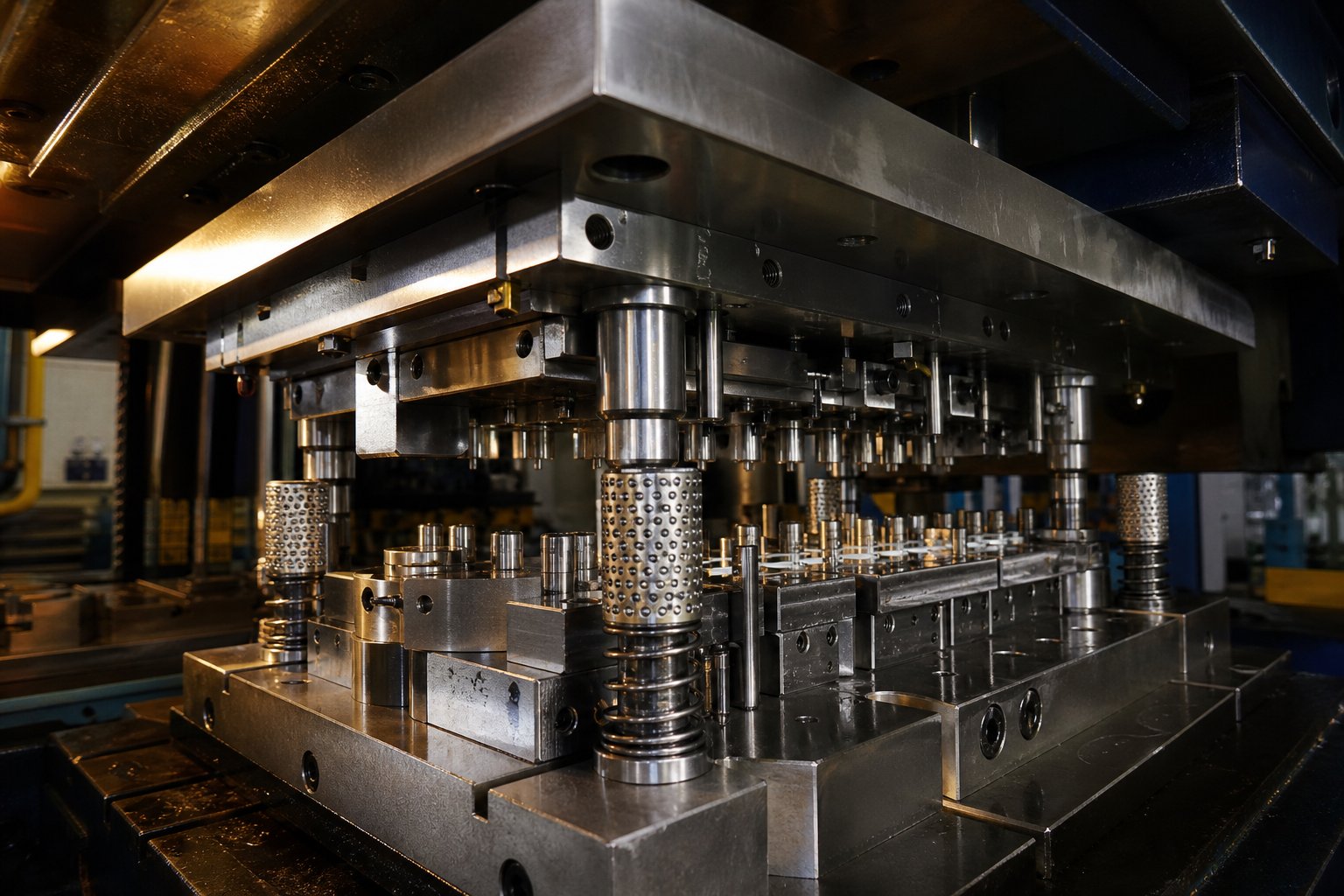
A production run stamping die is a precision-engineered tool built from hardened steel or carbide inserts, designed to produce identical metal parts at high volume with repeatable accuracy over hundreds of thousands or millions of press strokes. Unlike prototype or short-run soft tooling, it represents a long-term capital investment in manufacturing consistency.
Defining a Production Run Stamping Die
When you hear "stamping dies" in a production context, the conversation centers on tools that survive extreme duty cycles without drifting out of tolerance. A production run metal stamping die typically features hardened tool steel construction (grades like D2, A2, or carbide inserts), precision-ground cutting and forming details, and engineered strip guidance systems that keep material indexed to within thousandths of an inch station after station.
These dies integrate pilots, positive strippers, and robust spring systems that maintain alignment under continuous high-speed operation. Every component is built to resist wear, deflection, and thermal distortion across millions of hits, making the standard die set a foundation of repeatable output rather than a disposable prototype tool.
How Production Dies Differ from Prototype Tooling
Prototype and short-run dies serve a different purpose. They validate part geometry quickly and cheaply, often using softer materials like aluminum, zinc-based alloys, or non-heat-treated steel. The tradeoff is lifespan and precision. A prototype stamp and die set might handle 1,000 to 10,000 hits before wear affects part quality, while a production-grade tool is engineered for 100,000 to well over 1,000,000 cycles at full tolerance.
| Attribute | Prototype / Short-Run Die | Production Run Die |
|---|---|---|
| Primary Material | Aluminum, mild steel, soft alloys | D2, A2, M2, carbide inserts |
| Expected Lifespan (Hits) | 1,000 – 10,000 | 100,000 – 1,000,000+ |
| Tolerance Capability | Moderate (±0.005" typical) | Tight (±0.001" or better) |
| Typical Lead Time | 1 – 4 weeks | 8 – 16 weeks |
The differences go beyond material hardness. Production dies incorporate replaceable inserts, precision-ground guide posts, and in-die sensing, all features absent from a standard die built for quick validation runs.
When a Production Die Becomes the Right Investment
So when does it make sense to commit the budget? Three factors drive that decision:
- Volume expectations - If your program calls for tens of thousands of parts or more, the per-piece economics of dies and stamping at production grade far outperform repeated short-run tooling cycles.
- Part criticality - Safety components, assemblies requiring consistent fit, or parts feeding automated downstream processes demand the repeatability only hardened tooling delivers.
- Tolerance requirements - When specifications tighten below ±0.002", softer tooling simply cannot hold dimensions across meaningful quantities.
The upfront cost is higher and the lead time longer, but a properly specified production die pays for itself by eliminating scrap, reducing press downtime, and delivering part-to-part consistency that downstream operations depend on. The real question is not whether you can afford production tooling, but whether your volume and quality targets can survive without it.
That cost-versus-capability tradeoff raises a deeper question: which type of die architecture best fits your specific production scenario?
Types of Stamping Dies Mapped to Production Run Volumes
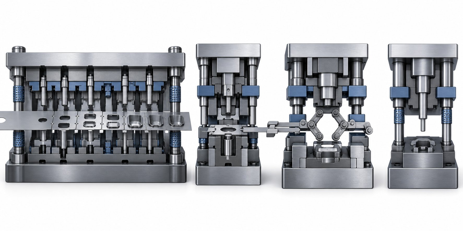
Choosing among the types of stamping dies is not purely an engineering exercise. It is a production planning decision that locks in your cycle speed, unit cost curve, and capacity constraints for the life of the program. Each die architecture solves a different equation of volume, part complexity, and press economics.
Progressive Dies for High-Volume Continuous Runs
Imagine a continuous metal strip feeding through a single die set with multiple stations, each performing a distinct operation - punching, bending, coining, trimming - in one press stroke. That is long run progressive stamping in action. The workpiece stays attached to the carrier strip from first hit to final separation, eliminating part handling between operations.
This architecture dominates high-volume production for a reason. Progressive stamping and fabrication lines can operate at 200 to 600+ strokes per minute, producing complex finished parts with minimal labor intervention. The tradeoff is upfront tooling cost - progressive dies range from $30,000 to over $250,000 depending on station count and tolerance demands - but per-part cost drops dramatically once volumes justify that investment. Economic viability typically begins around 50,000 to 100,000 annual units.
Long-run progressive stamping also reduces material waste through optimized strip layouts and eliminates secondary operations by building multiple forming steps directly into the die.
Compound Dies for Tight-Tolerance Flatness
Compound die stamping takes a different approach: multiple cutting and forming operations happen simultaneously in a single press stroke, but without the sequential station progression. The entire part is completed at once.
This makes compound stage dies ideal for flat parts - washers, shims, electrical laminations - where superior flatness and concentricity matter more than geometric complexity. Because all operations occur in one plane during one stroke, parts come out flatter than those produced by progressive methods where strip tension can introduce slight distortion.
Tooling costs run lower than progressive dies, and the simpler structure means less intensive maintenance. However, compound dies are limited to relatively simple geometries and are not suitable for deep-drawn or multi-bend parts.
Transfer and Single-Station Dies for Large or Deep-Drawn Parts
When part geometry is too large for a carrier strip, or when deep drawing would tear the connection points, transfer dies become the answer. Here, the blank is separated from the strip early and moved between independent stations by mechanical fingers or automation. This opens up design possibilities - threading, ribs, knurling, and deep draws - that progressive methods cannot accommodate.
Single-station dies serve dedicated operations on larger parts or when production volumes do not justify multi-station complexity. They offer lower tooling cost but require more handling and slower cycle times.
| Die Type | Best Volume Range | Part Complexity | Typical Cycle Speed | Relative Tooling Cost |
|---|---|---|---|---|
| Progressive | 50,000 – 1,000,000+ parts/year | High (multi-operation) | 200 – 600+ SPM | High to very high |
| Compound | 10,000 – 500,000 parts/year | Low to moderate (flat parts) | High (single stroke) | Low to medium |
| Transfer | 25,000 – 500,000 parts/year | High (large or deep-drawn) | Moderate | High |
| Single-Station | 1,000 – 50,000 parts/year | Low to moderate | Low to moderate | Low |
Die type selection is a production planning decision, not just an engineering preference. The architecture you choose defines your cost curve, throughput ceiling, and maintenance burden for the entire program lifecycle.
Understanding the types of dies and their volume sweet spots is only the first layer. The next variable - your specific production quantity target - further refines how the die itself gets specified, from the number of stations to the grade of tool steel inside it.
Production Volume Thresholds That Drive Die Design Decisions
Your annual part count does more than fill a line on a purchase order. It dictates die material, station count, press compatibility, and ultimately, the cost structure of every piece that comes off the tool. Yet volume classifications in metal stamping remain surprisingly vague across the industry. Here is a practical framework that connects production quantity to the engineering choices inside the die.
Short Run Production and Bridge Tooling
Short run stamping typically covers production quantities under 10,000 to 50,000 parts. At these volumes, committing to fully hardened, multi-station progressive tooling rarely makes economic sense. The upfront tooling investment remains high relative to the number of parts produced, so designers simplify wherever possible.
What does that look like in practice? Fewer die stations, softer insert materials (non-heat-treated steel or even zinc-based alloys), and streamlined geometries that reduce machining time. Bridge tooling - temporary production-capable dies built while the final tool is in development - falls into this category as well. It gets parts flowing to market without waiting 12 to 20 weeks for hardened progressive tooling.
Short-run metal stamping dies might use manual or semi-automatic operation and prioritize speed-to-production over longevity. They are good enough for market launches, engineering validation builds, or programs where demand has not yet stabilized enough to justify full production investment.
Medium and Long Run Volume Thresholds
Medium-run production generally spans 10,000 to 100,000 parts. At this range, the economics shift. Hardened steel tools become justifiable because the cost per part drops meaningfully when spread across tens of thousands of units. Die designs grow more complex - progressive or transfer architectures become viable, and tighter tolerances are sustainable because the tool steel can withstand the cumulative wear.
Long run metal stamping crosses the 100,000-part threshold and extends into the millions. Here, tooling costs are high in absolute terms but low per piece, and the focus shifts entirely to maximizing production efficiency, press uptime, and part consistency over extreme duty cycles.
At these volumes, high speed stamping becomes the norm. Presses operating at 800+ strokes per minute demand dies engineered specifically for that duty cycle - extra-thick die shoes, large roller guide pins, minimized strip lift, and robust part ejection systems. A high speed stamping press at those rates feeds material more than 13 times per second, meaning every component inside the die must tolerate extreme inertia forces without flexing, shifting, or breaking.
High speed production at this level also requires tighter integration between the die and auxiliary equipment: servo feeds, straighteners, payoff reels, and in-die sensors all need to function as a synchronized system rather than independent components.
How Volume Targets Shape Die Specification
The production quantity you commit to ripples through every design parameter in the die. Consider how these key specifications shift as volume increases:
- Number of stations - Low-volume dies may use 3 to 5 stations; high-volume progressive dies commonly run 10 to 20+ stations to consolidate operations and eliminate secondary processing.
- Die material grade - Short-run tools use unhardened or semi-hardened steels; medium-run tools step up to hardened D2 or A2; long-run tools may incorporate M2 high-speed steel or carbide inserts at wear-critical punch and die details.
- Surface treatments - High-volume dies often receive TiN, TiCN, or other PVD coatings to reduce friction, resist galling, and extend sharpening intervals across hundreds of thousands of hits.
- Press compatibility - Larger runs justify dedicated press lines with servo feeds, die protection systems, and automated scrap removal. Short-run dies may run on general-purpose presses with manual feed setups.
- Strip layout optimization - At high volumes, even small improvements in material utilization (tighter nesting, narrower carrier strips) save thousands of dollars in raw material over the program life.
Material type and thickness also factor heavily into die specification. Production run dies commonly process carbon steel (0.005" to 0.250" thick), stainless steel, aluminum, copper alloys, and brass. Harder and thicker workpiece materials demand tougher die steels, larger clearances, and more frequent maintenance intervals. Stainless steel and high-strength alloys, for example, often require carbide inserts at cutting stations to resist abrasive wear that would quickly degrade conventional tool steels at production volumes.
These volume-driven specifications define not just how the die performs on day one, but how it holds up across its entire service life. That durability question leads directly to the structural choices - hardened construction, insert design, and component engineering - that separate a production die from a short-lived prototype tool.
Die Construction Methods for Production Run Longevity
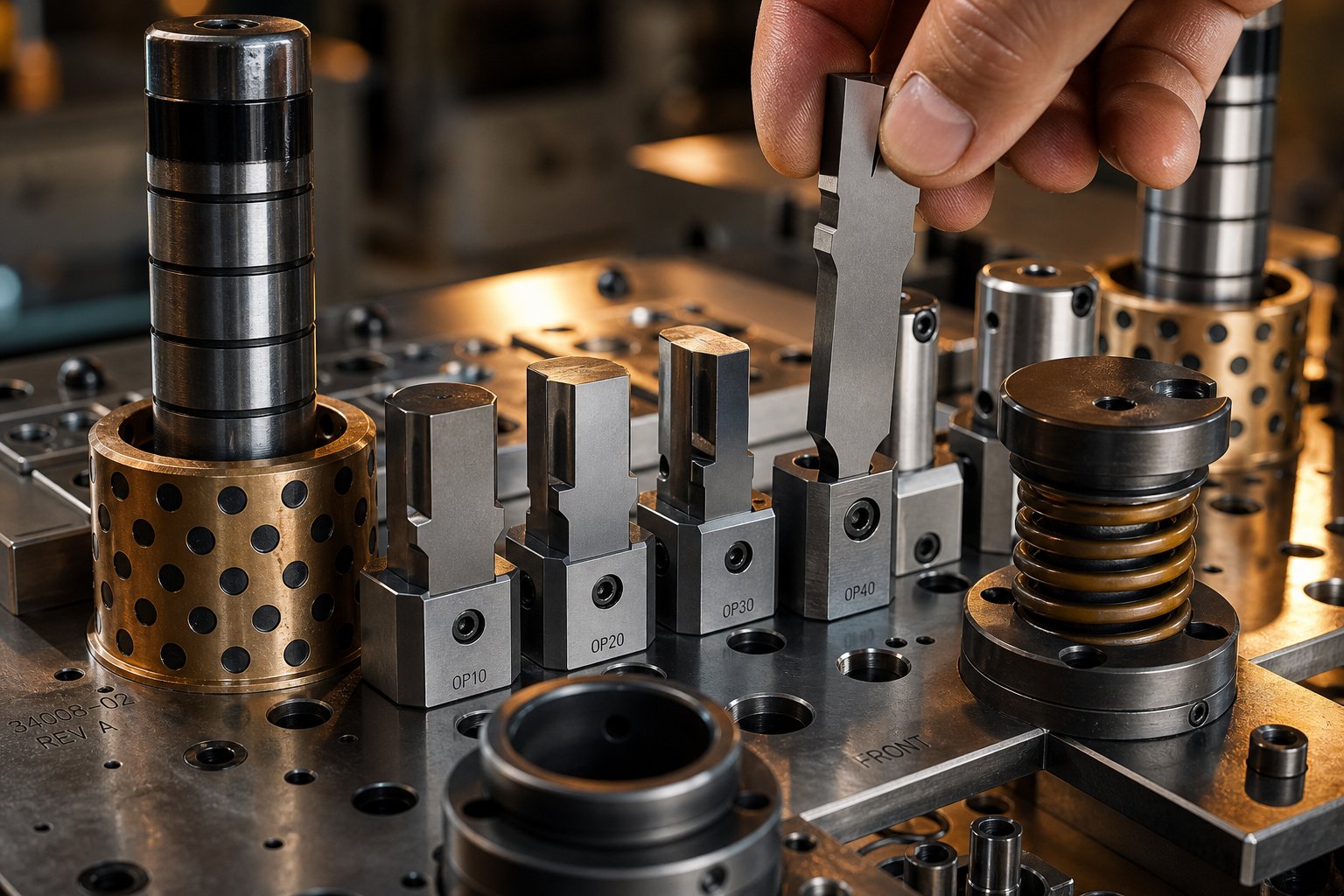
A die that runs for a week and a die that runs for three years may look similar on the outside. The difference lives in the construction decisions buried inside - the steel grade in each punch, whether cutting details are solid or insert-style, and how every component resists the cumulative fatigue of millions of press cycles. These structural choices are what separate steel stamping dies built for production longevity from tooling designed to get through a short validation run.
Hardened Tool Steel and Carbide Insert Construction
Material selection inside a production die is not a single decision. It is a station-by-station engineering judgment that matches each detail's stress environment to the right stamping die steel.
The most common choices break down like this:
- D2 (High-carbon, high-chromium) - The industry benchmark for blanking and piercing stations. D2 delivers exceptional wear resistance at HRC 60-62, making it the default for cutting operations on carbon steel and softer alloys. Its weakness is brittleness - coarse carbides act as stress concentrators under heavy impact.
- A2 (Air-hardening) - Offers a balanced profile with less wear resistance than D2 but notably higher toughness. A2 also undergoes roughly 40% less dimensional change during heat treatment than oil-hardening steels, making it ideal for detailed punch geometries where post-heat-treat accuracy matters.
- M2 (High-speed steel) - Used at stations where frictional heating from high-speed operation would soften conventional cold-work steels. M2 retains its hardness at elevated temperatures, making it suitable for dies running at 600+ strokes per minute.
- DC53 (Enhanced cold-work steel) - A modern evolution of D2 that reaches 62-64 HRC while delivering roughly twice the toughness of D2. DC53's high-temperature tempering compatibility also makes it an excellent substrate for PVD coatings like TiN or DLC.
- Carbide inserts - Reserved for the highest-wear stations or when processing abrasive materials like stainless steel and high-strength alloys. Carbide delivers hardness above 90 HRA and can outlast tool steel by 5 to 10 times, though it requires careful support to avoid cracking under impact loads.
The selection logic is straightforward: match the stamping die steel grade to the workpiece material's abrasiveness, the station's dominant stress mode (wear vs. impact), and the expected hit count before maintenance. A piercing punch cutting 0.040" stainless at 400 strokes per minute faces a completely different wear environment than a forming station bending 0.020" copper - and the die steel at each station should reflect that difference.
Insert-Style vs. Solid Die Construction
Here is where production thinking diverges sharply from prototype logic. Solid dies - where the punch or die detail is machined directly from a single block - offer excellent rigidity and accuracy. For short runs, that simplicity works fine. But when a cutting edge dulls at hit 80,000 in a million-piece program, you do not want to pull the entire die section for regrinding.
Insert-style construction solves this by separating wear components from the structural die body. The punch or cutting detail is a replaceable piece pressed or bolted into a retainer or pocket, allowing it to be swapped without disturbing the rest of the die assembly.
The production advantages are significant:
- Faster maintenance - A worn insert can be replaced or reground and reinstalled in minutes rather than hours. The die stays on the press longer.
- Lower regrind cost - You sharpen a small insert rather than a large monolithic block, reducing material removal and machine time.
- Reduced downtime - Spare inserts kept in inventory mean zero wait time for regrinding. Swap, resume, and sharpen the worn insert offline.
- Material optimization - The expensive carbide or PM steel only goes where wear demands it. The supporting retainer can be a tougher, less costly steel that resists shock without needing extreme hardness.
Solid dies still have a role in production when rigidity is paramount - heavy forming stations or large blanking operations where insert interfaces could introduce deflection. But for piercing, trimming, and detail cutting across a multi-station progressive die, insert construction is the production standard because it directly reduces cost-per-hit over the tool's lifecycle.
Critical Stamping Die Components That Enable Production Longevity
A production die is a system, not a single tool. Every component plays a role in maintaining precision across millions of cycles. When one element fails or drifts, part quality suffers immediately. Here are the critical stamping die components and what they contribute:
- Die set (upper shoe, lower shoe, guide posts) - The foundation where all other die tools and components are mounted. Precision-ground die shoes maintain parallelism between upper and lower halves, while guide posts and bushings (manufactured to tolerances within 0.0001") ensure repeatable alignment stroke after stroke.
- Punches - The cutting and forming tools that directly contact the workpiece. Production punches are typically through-hardened and precision-ground, available in standard or custom nose geometries to match the part profile.
- Die buttons - The counterpart to punches, providing the opposing cutting edge. Die buttons are offset slightly larger than the punch nose (typically 5-10% of material thickness per side) to establish the correct cutting clearance.
- Strippers - Hold the strip flat against the die face and strip material off the punch during retraction. Production dies use guided strippers (spring-loaded plates) rather than simple fixed strippers, improving strip control and preventing slug pulling at high speeds.
- Pilots - Precision pins that register the strip at each station by entering previously pierced holes. They compensate for slight feed inaccuracies and ensure every station operates on correctly positioned material.
- Die springs (mechanical or nitrogen gas) - Provide the force that controls stripper pressure, pad holding force, and part ejection. Nitrogen gas springs deliver more consistent force over longer travel and are common in production dies requiring higher stripping force.
- Retainers - Hold punches and die buttons in position within the die plates. Ball-lock retainers allow quick punch changes without removing the die from the press.
- Backing plates - Hardened plates behind punch heads that distribute impact force and prevent punches from driving into softer die shoes over time.
Each of these components is designed to prevent specific failure modes that become inevitable over extended production. Guided strippers prevent slug pulling - where a cut slug sticks to the punch face and gets carried back up, jamming the die or marking the next part. Properly sized pilots prevent mis-indexed strips from producing out-of-tolerance parts. Backed punches prevent head mushrooming that would shift punch position by thousandths of an inch over hundreds of thousands of hits.
The stamping die set, taken as a whole, functions like a precision machine rather than a static tool. Every clearance, spring rate, and surface finish is engineered to remain stable across the die's full production life - and when something does wear, the insert-based construction philosophy ensures it can be restored quickly without rebuilding the entire assembly.
Getting all these structural decisions right does not happen on the shop floor. It starts much earlier, in the engineering phase where feasibility analysis, simulation, and precision machining converge to bring a production die from concept to first approved part.
Die Engineering Process from Feasibility to First Article
A production run stamping die does not begin on a machining center. It begins as a question: can this part be reliably formed, at this tolerance, in this material, at production speed? The engineering lifecycle that answers that question spans months and involves multiple validation stages before steel ever meets strip in a production press. Each phase reduces risk, and skipping any of them multiplies cost downstream.
Feasibility Analysis and DFM Collaboration
Every stamping tool and die project starts with a feasibility assessment. Engineers evaluate the part geometry against forming limits - minimum bend radii relative to material thickness, draw depth ratios, and whether features can be produced in a stamping operation without secondary machining.
This is where DFM (Design for Manufacturability) collaboration between the product designer and the die engineer pays off. A comprehensive DFM analysis confirms that bend radii meet or exceed material thickness, that punch diameters are large enough to prevent breakage, and that tolerance strategies target mean values to compensate for natural tool wear over the die's lifecycle.
For progressive dies, this phase also defines the strip layout - the sequence of stations, material utilization, carrier strip width, and piloting strategy. Idle stations are often planned in advance to accommodate future engineering changes without requiring a full die rebuild. Strip layout decisions lock in material cost per part for the entire program, making this one of the highest-leverage engineering activities in the process.
CAE Simulation and Virtual Die Tryout
Imagine being able to test your die before it physically exists. That is exactly what CAE (Computer-Aided Engineering) simulation delivers. Using finite element analysis, engineers model how the sheet metal will behave under forming forces - predicting where cracks might initiate, where wrinkling will develop, where excessive thinning creates weak spots, and how much springback to expect after the press opens.
Virtual die tryouts allow manufacturers to identify and resolve potential defects before production begins, significantly reducing physical trial-and-error costs. The simulation also optimizes blank contours to maximize material utilization and predicts minimum required press force - critical data for selecting the right die stamping machine and press line.
For challenging materials like advanced high-strength steels and aluminum alloys, simulation is especially valuable because these materials exhibit high springback magnitudes that are difficult to control through physical iteration alone. Digital springback compensation adjusts die geometry before machining, so the first physical tryout lands closer to final specification.
Precision Machining, Assembly, and Trial Runs
With simulation validated and die design finalized, manufacturing begins. The machining sequence for production dies in manufacturing typically follows this progression:
- CNC milling - Rough and semi-finish machining of die shoes, retainer plates, and form details to near-net geometry.
- Heat treatment - Hardening and tempering of tool steel components to target HRC values, followed by stress relief.
- Wire EDM - Precision cutting of punch profiles, die openings, and complex geometries to tolerances within 0.0001" where conventional milling cannot reach.
- Surface grinding - Final finishing of mating surfaces, die faces, and punch flats to achieve parallelism and surface finish specifications.
- Assembly and fitting - Progressive assembly of components into the die set, with blue-matching of critical surfaces and verification of clearances at each station.
Once assembled, the die moves to tryout presses for initial sampling. Trial runs validate material flow, confirm dimensional accuracy, and reveal any issues that simulation could not fully predict - subtle interactions between stations, strip lifting behavior, or scrap ejection problems that only appear under real press conditions.
First article inspection is the final gate. Parts from the trial run undergo full dimensional reporting against the part print, often including CMM measurement, optical scanning, and GD&T verification. For automotive die stamping programs, this feeds directly into the PPAP (Production Part Approval Process) submission that releases the die for full production.
Suppliers like YICHEN offer end-to-end capability spanning this entire lifecycle - from initial feasibility and CAE simulation through precision machining, trial runs, and final dimensional inspection - giving sourcing teams a single point of accountability from concept through production-ready tooling.
The engineering investment in this process is substantial, but it directly determines the die's production economics. Every simulation iteration avoided, every tryout loop eliminated, and every first-article pass achieved on schedule translates into lower total program cost - a relationship that becomes clearer when you examine how tooling investment amortizes across production volume.
Cost-Per-Part Economics of Production Run Die Investment
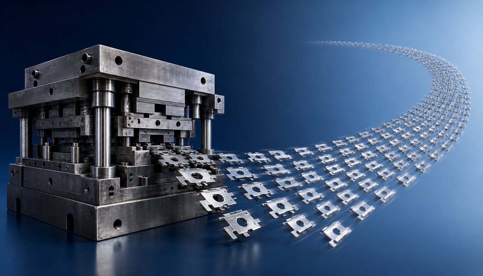
Here is the math that drives every tooling decision: a $100,000 die producing 1,000,000 parts adds $0.10 per piece. That same die producing only 5,000 parts adds $20.00 per piece. The die itself has not changed - only the volume flowing through it. This amortization logic determines whether production-grade tooling is a smart investment or an expensive mistake, and understanding it separates strategic sourcing from guesswork.
How Die Cost Amortizes Across Production Volume
Think of a production run stamping die as a fixed cost that gets divided across every part it produces. The more parts you run, the smaller the tooling contribution to each unit. At low volumes, that contribution dominates your piece price. At high volumes, it becomes negligible - often just pennies per part - leaving raw material and press time as the primary cost drivers.
This is why a higher initial die investment often yields lower total program cost for large run stampings. A $150,000 progressive die with 15 stations may look expensive next to a $40,000 simplified tool, but if the progressive die eliminates three secondary operations (deburring, tapping, and a separate forming step), the downstream savings per part compound across every unit produced. Multiply that per-part savings by 500,000 pieces, and the expensive tool becomes the cheaper program.
The relationship is non-linear in practice. Early production absorbs the tooling cost rapidly - your first 10,000 parts carry a heavy per-unit burden. But as volume climbs past 50,000, then 100,000, the amortized tooling cost flattens toward zero while the per-part savings from eliminated secondary operations continue compounding. This is the economic engine behind every decision to invest in production-grade tooling over short-run alternatives.
Factors That Influence Production Die Pricing
Die pricing is not a single number pulled from a catalog. It reflects the cumulative complexity of everything engineered into the tool. When you receive a quote for production tooling, the price is shaped by these primary cost factors:
- Number of stations - Each station in a progressive die adds design time, machining, heat treatment, and fitting. A 6-station die costs significantly less than a 16-station die performing the same operations in a more optimized sequence.
- Die material grade - D2 tool steel costs less than M2 high-speed steel, which costs less than carbide inserts. The workpiece material's abrasiveness and the target hit count between sharpenings determine which grade the toolmaker specifies.
- Part complexity - Tight radii, deep draws, close-tolerance features, and multiple bend axes all increase machining time and the number of discrete components inside the die.
- Tolerance requirements - Holding ±0.001" demands precision grinding, tighter component fits, and more rigorous inspection than ±0.005". Each step tighter adds cost to both initial build and ongoing maintenance.
- Secondary operations built into the die - In-die tapping, in-die assembly, contact welding, or sensor integration eliminates downstream processes but adds complexity (and cost) to the tool itself.
- Press tonnage requirements - Larger, thicker, or higher-strength parts require dies built to withstand greater forming forces. Heavier die shoes, larger guide posts, and more robust spring systems increase material and machining costs.
Progressive die tooling generally ranges from $30,000 to over $250,000 depending on how these factors combine. High-tolerance stainless steel parts with many forming stations sit at the top of that range, while simple carbon steel geometries with fewer operations land at the lower end.
Comparing Tooling ROI Across Run Lengths
The breakeven question is straightforward: at what volume does the more expensive production die deliver a lower total cost than repeated short-run tooling cycles? The answer depends on your specific cost structure, but the pattern is consistent across industries.
| Factor | Short-Run Soft Tooling | Production-Run Hardened Tooling |
|---|---|---|
| Upfront Cost Range | $5,000 – $30,000 | $30,000 – $250,000+ |
| Expected Die Life | 1,000 – 50,000 hits | 500,000 – 2,000,000+ hits |
| Per-Part Cost Trend | Remains high (limited amortization) | Drops sharply as volume increases |
| Maintenance Frequency | Frequent replacement or rebuild | Scheduled sharpening at long intervals |
For short-run metal stamping - say 5,000 to 20,000 parts - the math often favors soft tooling. You spend less upfront, accept shorter die life, and move on. But when demand scales past 50,000 pieces, the economics invert. Short-run dies wear out, requiring replacement or rebuild cycles that add both cost and lead time. A production die, meanwhile, is still running on its original sharpening schedule with parts-per-minute output that soft tooling cannot match.
There is also a hidden cost advantage that the table above does not capture: in-die operations. Production dies can integrate tapping, hardware insertion, contact assembly, or even in-process sensing directly into the press stroke. Each operation consolidated into the die eliminates a downstream handling step, a separate machine, and the associated quality risk of moving parts between processes. For large run stampings with high annual volumes, these value-adds shave cents per part that compound into substantial savings over the program life.
The cost-per-part equation, however, only tells half the story. A die that delivers great economics on day one but degrades after 200,000 hits - requiring unplanned rebuilds or producing scrap - erases those savings quickly. The other half of the economic picture is how well the die maintains its performance across its full intended lifespan, which depends entirely on maintenance strategy and the ability to catch failure modes before they cascade into downtime.
Die Lifespan and Maintenance Through the Production Lifecycle
How many hits does a production die actually last? The answer ranges from 250,000 to well over 7 million - and as die science expert Art Hedrick notes, some dies make 7 million hits per day for five years before retirement. That enormous range is not vagueness - it reflects real differences in die steel grade, workpiece material, press conditions, and maintenance discipline. Understanding the variables that control die lifespan, and building a maintenance strategy around them, is what separates shops that squeeze maximum value from their tooling investment from those constantly firefighting unplanned downtime.
Expected Die Lifespan by Construction and Material
There is no universal hit count that defines a die's end of life. Instead, lifespan is the product of several interacting variables, each capable of cutting tool life in half - or doubling it:
- Die steel grade - Tooling made from solid carbide delivers a fundamentally different lifespan than conventional tool steels like A2 or D2. Upgrading to CPM (powder metallurgy) steels or carbide inserts at high-wear stations can extend service life by 3 to 10 times compared to standard cold-work steels.
- Workpiece material - Harder, thicker, and more abrasive materials shorten tool life dramatically. Aluminum stamping dies, for example, face a paradox: aluminum is soft, but highly abrasive due to its oxide layer. It galls against tool steel surfaces, accelerating wear in ways that mild steel does not. High-strength steels and stainless alloys impose greater cutting forces, increasing edge breakdown rates.
- Press speed and stability - A well-maintained press with tight ram parallelism extends die life. A worn press with excessive deflection, vibration, or inconsistent shut height acts like a slow-motion wreck on the tooling. Even a precision-built die will fail prematurely in a press that cannot hold alignment under load.
- Section geometry - Larger, beefier stamping die parts withstand cumulative fatigue better than small, fragile inserts. Thin punches or narrow cutting features concentrate stress and are more susceptible to cracking over extended runs.
- Heat treatment accuracy - Properly heat-treated die sections possess the balance of hardness and toughness needed for long-term performance. Poorly heat-treated components - where quenching was uneven or tempering temperatures drifted - soften prematurely or crack under production loads.
Given all these factors, the most reliable way to estimate a specific die's expected life is to reference the production history of similar tooling running comparable materials at similar speeds. Without that benchmark, you are guessing - and in metal die stamping, guessing leads to either premature die replacement (wasted money) or unexpected failure mid-run (wasted production).
Preventive Maintenance and Regrinding Schedules
True preventive maintenance keeps a die performing at specification. It is not the same as die repair - which is what happens when maintenance is neglected and something breaks. The distinction matters. Preventive maintenance involves scheduled activities performed regardless of whether the die appears to need them, because wear is cumulative and often invisible until it produces scrap.
A production maintenance program typically includes:
- Sharpening intervals - Cutting edges dull progressively, producing burrs and feeding problems. Sharpening schedules are set based on hit counts (for example, every 50,000 to 150,000 strokes depending on material and steel grade), not waiting until burrs appear on finished parts.
- Spring replacement - Coil springs and gas cylinders fatigue over millions of cycles. Replace them at their rated life cycle, not after breakage causes a die crash.
- Inspection for loose components - Check all screws, dowel pins, and retainers at every scheduled pull. A single loose dowel can allow a die section to shift, damaging every station downstream.
- Surface condition checks - Inspect wear plates, cam surfaces, and forming details for galling or surface breakdown. Regrind and refit as needed before dimensional drift reaches the part.
- Cleaning and lubrication - Remove slug buildup, lubricant residue, and debris. Lubricate all mating surfaces to prevent corrosion between production runs.
When sharpening cutting sections, grinding technique matters. Using the wrong grinding wheel - one that loads up rather than breaking down freely - generates excessive heat that can soften or crack the die section. Flood coolant and appropriate wheel selection (matched to the specific tool steel being ground) prevent thermal damage during resharpening. Proper shear angles should also be maintained during grinding to keep cutting forces balanced across the die.
After any grinding operation, demagnetize all components. Surface grinders use powerful magnets to hold workpieces, and magnetized punches attract metallic debris and contribute to slug pulling during production.
Common Failure Modes and Mitigation Through Design
Even with disciplined maintenance, production dies face failure modes that are best addressed during the design phase rather than on the shop floor. Knowing what fails - and why - allows die engineers to build in preventive features from the start:
- Slug pulling - Cut slugs stick to the punch face and get carried back into the strip, damaging parts and the die. Causes include trapped air (vacuum), large cutting clearances, magnetized punches, and sticky lubricants. Design mitigations: punch face venting (air relief holes), reverse-taper die buttons that hold slugs in compression, spring-loaded slug ejectors, and proper cutting clearance specification to maintain interference fit between slug and matrix.
- Strip misfeeds - The strip advances too far, too short, or skews sideways, placing material out of position for the next station. Mitigations: oversized pilots that self-correct minor feed errors, positive strip lifters that prevent drag, in-die misfeed sensors that stop the press before damage occurs, and feed-length monitoring systems.
- Punch breakage - Small-diameter punches or punches with high length-to-diameter ratios concentrate bending stress and snap under production loads. Mitigations: guided strippers that support the punch close to the cutting point, stepped punch heads that increase cross-section away from the tip, shear angles that reduce snap-through force, and proper backing plates that prevent head mushrooming.
- Galling - Workpiece material welds itself to the die surface under pressure and heat, tearing the part and scoring the tool. Common with stainless steel, aluminum, and titanium. Mitigations: PVD coatings (TiN, TiCN, DLC) on forming surfaces, polished die radii, proper lubrication, and selecting die steels with high chromium or vanadium content that resist adhesion.
- Die section cracking - Thermal stress from grinding, excessive force concentration, or improper heat treatment leads to crack propagation in hardened die details. Mitigations: stress-relief tempering after grinding, proper fillet radii at geometry transitions, and avoiding sharp internal corners that act as crack initiation points.
Each of these failures carries a cost far beyond the broken component itself. A single pulled slug carried through a progressive die can damage every station in the tool. A broken punch can crash the die, requiring days of repair and thousands of dollars in replacement parts. Designing against these modes from the beginning - rather than patching them after they occur - is what keeps a production die running profitably across its full intended life.
Knowing when a die reaches end-of-life is equally important. Retirement criteria vary, but common indicators include: dimensional drift that cannot be corrected by resharpening, cumulative shimming that exceeds design tolerance, repeated failures at the same station despite proper repair, or material condition degradation where heat checking or microcracks make further production risky.
Maintaining performance across millions of cycles is one side of the longevity equation. The other side is verifying that the parts emerging from the die actually meet specification - not just at first article, but continuously throughout the production run. That verification depends on quality systems engineered directly into the die itself.
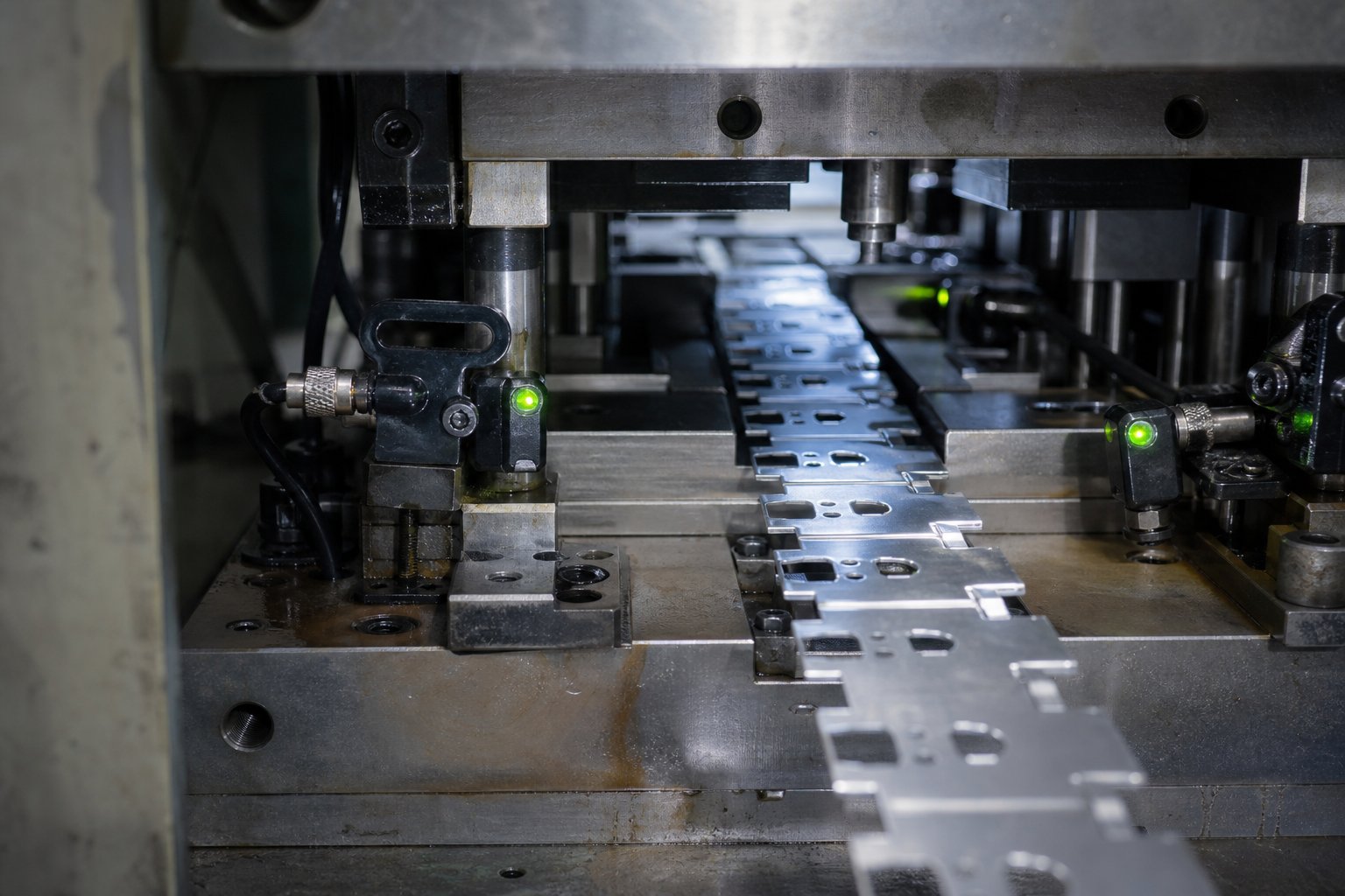
Quality Control Built Into Production Run Stamping Dies
Quality does not happen at the end of a production line. In a well-engineered sheet metal stamping die, it is built into the tool itself - embedded in sensors, strip control features, and validation protocols that catch problems before they produce scrap. The distinction matters: inspecting parts after the fact catches defects, but in-die quality systems prevent them.
In-Die Sensors and Automated Monitoring
When a high-speed stamping press runs at 400 or more strokes per minute, a single misfeed can cascade into a die crash within milliseconds. Human reaction time cannot protect the tool. That is why production dies integrate electronic sensing systems that monitor every stroke and halt the press the instant something deviates from normal.
Common in-die sensing technologies include:
- Misfeed detection - Proximity or photoelectric sensors verify that the strip has advanced the correct pitch before the press completes its next stroke. If feed falls short or overshoots, the press stops before pilots force misaligned material into cutting stations.
- Part ejection sensors - Photoelectric eyes confirm that finished parts and scrap slugs have cleared the die before the next cycle. A stuck part carried back into the tool causes immediate damage.
- Stripper position monitoring - Sensors under spring strippers detect whether the stripper has fully returned after each stroke. Monitoring stripper position at each corner also detects pulled slugs - if one corner lifts higher than expected, a slug is likely trapped beneath.
- Double-blank detection - Sensors measure material thickness at the die entry, stopping the press if two layers of material feed simultaneously.
- Cam return verification - Side-action cams must fully retract before the press opens. Sensors confirm cam position to prevent interference between moving components.
Modern die protection controllers use resolver-based timing accurate to one-third of a degree of crankshaft rotation, enabling detection of events lasting less than 10 milliseconds. The controller monitors each sensor against programmed timing windows - some signals should be momentary (part ejection), others continuous (material presence), and others cyclic (strip feed). Fail-safe logic also catches malfunctioning sensors: if a cyclic sensor stays actuated for an entire stroke, the system flags it rather than assuming normal operation.
Best practice is to permanently wire all die-mounted sensors to a junction box on the lower die shoe, connected to the press-mounted interface through a single master cable. This eliminates wiring errors during setup and prevents the cable wear that causes most sensor failures in production environments.
Bypass Notches and Strip Control Features
Sensors catch gross misfeeds, but what about subtle indexing errors that fall within sensor tolerances yet still produce defective parts? This is where bypass notches serve as a mechanical quality gate inside the sheet metal stamping die.
The purpose of bypass notches in stamping dies is straightforward: they create physical interference that prevents a mis-indexed strip from advancing into downstream stations. In progressive dies, negative and positive bypass notches work together to verify strip position mechanically at every stroke.
- Positive bypass notches - A small tab or protrusion punched into the strip at an early station. If the strip feeds correctly, this tab passes harmlessly through a relief in later stations. If the strip over-feeds or under-feeds, the tab contacts solid die steel and physically blocks advancement - stopping the press or jamming the strip before a defective part can be produced.
- Negative bypass notches - A notch or slot cut into the strip that must align with a corresponding sensor or mechanical feature downstream. If alignment fails, the strip cannot proceed.
Together, negative and positive bypass notches in sheet metal stamping dies create a fail-safe indexing verification system that operates independently of electronic sensors. Even if a sensor malfunctions or is bypassed, the mechanical notch system prevents the most damaging outcome: producing parts from incorrectly positioned material. This redundancy is critical on a high-speed stamping press where a single misindexed hit can damage multiple stations simultaneously.
Die Validation and PPAP Approval
Before a production die is released for full-volume operation, it must pass a formal validation sequence that proves it can produce conforming parts repeatably - not just once, but consistently under normal production conditions.
The validation process typically follows this sequence:
- Die tryout - Initial sampling on a tryout press to verify material flow, strip feeding, and part formation. Engineers observe each station, checking for anomalies like wrinkling, thinning, or ejection problems.
- First article inspection (FAI) - Parts from the tryout run undergo full dimensional measurement against the part drawing. Every GD&T callout, hole position, bend angle, and surface finish requirement is verified, typically using CMM and optical measurement systems.
- Dimensional reporting - Results are documented in a formal dimensional layout showing actual measured values against nominal and tolerance for every critical characteristic.
- Production Part Approval Process (PPAP) - For automotive and other regulated industries, PPAP packages validate the supplier's ability to reliably produce parts that meet all customer requirements. A PPAP submission includes 18 elements: design records, process flow diagrams, control plans, measurement system analysis, SPC studies, dimensional results, material certifications, and more.
PPAP is not a one-time event. It is required again whenever tooling is modified, relocated, or inactive for more than one year. This ensures that any change - however minor - is revalidated before production resumes.
Quality begins in die design, not at final inspection. Sensors, bypass notches, and validation protocols are engineering decisions made months before the first production part ships.
These quality systems protect the die and the parts it produces. But even the best-designed tool, monitored by the best sensors, eventually depends on a broader decision: who built it, what capabilities they brought to the project, and whether they can support the tooling through its full production lifecycle. That question leads directly to supplier evaluation.
Selecting the Right Production Run Die Partner
A production run stamping die is only as reliable as the partner behind it. The best die design in the world falls apart if the supplier lacks machining precision, cannot run a proper tryout, or goes silent for weeks mid-build. For sourcing managers evaluating die and stamping suppliers - especially for programs involving automotive stamping dies or other high-criticality applications - the selection criteria extend well beyond quoted price.
Key Capabilities to Evaluate in a Die Supplier
Not all die shops are equal. Some specialize in design but outsource machining. Others machine beautifully but lack simulation capability. The strongest production die partners are vertically integrated - handling the full process from feasibility through final inspection under one roof. That integration eliminates handoff errors, compresses timelines, and gives you a single point of accountability when issues arise.
When evaluating potential suppliers for sheet metal stamping dies, rank them against these criteria:
- Vertically integrated design-through-inspection capability - The supplier handles CAE simulation, DFM collaboration, precision machining, assembly, die tryout, and dimensional inspection internally. This is the strongest indicator of process control and schedule reliability.
- In-house precision machining capacity - Wire EDM, CNC milling, and surface grinding performed on-site rather than farmed out. Look for equipment lists and machine specifications that match your die complexity.
- Die tryout presses - Dedicated tryout presses (not production presses borrowed between runs) with tonnage matching your production conditions. Tryout on an undersized press masks problems that surface later in production.
- Metrology and inspection equipment - CMMs, optical comparators, and surface measurement tools capable of validating every GD&T callout on your part drawing. Ask for sample dimensional reports from previous programs.
- Material sourcing transparency - Certified die steel sourced from known mills with full traceability. Verify that the supplier provides material test reports and heat treatment records as standard documentation.
- Engineering communication discipline - Regular progress updates, DFM feedback within days (not weeks), and clear change-management protocols. Silence during the tooling phase is a warning sign that issues are compounding without resolution.
- Lifecycle support - Willingness to support regrinding, spare insert supply, and engineering changes after production launch. A supplier who disappears after delivery leaves you managing maintenance alone.
For automotive dies and other regulated-industry programs, add IATF 16949 certification, PPAP submission capability, and experience with customer-specific quality requirements to your evaluation. These are non-negotiable in the automotive stamping die space, where traceability and process documentation standards are especially strict.
From Research to RFQ-Ready Specification
You have identified capable suppliers. The next step is translating your production requirements into an RFQ package that gets you accurate, comparable quotes - not estimates padded with contingency because information was missing.
A complete RFQ for a metal stamp die should include:
- Part drawings - 2D prints with full GD&T callouts and a 3D CAD model (STEP or native format). Include revision level and any pending ECN changes.
- Material specification - Alloy, temper, thickness, and any surface finish requirements on the incoming coil or blank.
- Annual volume targets - Include ramp-up projections if applicable. The difference between 50,000 and 500,000 annual parts changes every specification inside the die.
- Tolerance callouts - Highlight critical dimensions separately from general tolerances. Call out any features requiring Cpk studies.
- Secondary operations - Specify whether tapping, hardware insertion, plating preparation, or in-die sensing needs to be built into the tool versus handled downstream.
- Press information - If you have a designated press line, provide bed size, tonnage, shut height, and feed equipment details so the die is designed for your specific production environment.
Suppliers like YICHEN, who offer end-to-end capability from CAE simulation and DFM collaboration through precision machining, trial runs, and dimensional inspection, can take this RFQ package and return not just a price - but a feasibility assessment that identifies risks before tooling commitment. That consultative approach, where your die and stamping partner flags potential issues during quoting rather than discovering them during tryout, is the clearest signal of a supplier who protects your program timeline and budget.
Whether you are sourcing your first automotive stamping die or replacing an aging tool on a high-volume line, the framework remains the same: evaluate capability before cost, verify integration before claims, and choose a partner whose process discipline matches the precision you expect from the die itself.
Frequently Asked Questions About Production Run Stamping Dies
1. How long does a production run stamping die last?
A production run stamping die typically lasts between 500,000 and over 2,000,000 hits, with some high-quality dies running 7 million hits per day for years. Lifespan depends on die steel grade, workpiece material hardness, press speed, maintenance discipline, and heat treatment quality. Carbide inserts can outlast conventional tool steels by 5 to 10 times at high-wear stations. Regular preventive maintenance, including scheduled sharpening every 50,000 to 150,000 strokes, spring replacement, and surface inspections, maximizes the return on your tooling investment.
2. What is the difference between a progressive die and a compound die?
A progressive die moves a continuous metal strip through multiple stations sequentially, performing different operations (punching, bending, trimming) at each station in one press stroke. It excels at high-volume complex parts running 200 to 600+ strokes per minute. A compound die performs all cutting and forming operations simultaneously in a single stroke without station progression, making it ideal for flat parts like washers and laminations where superior flatness and concentricity are critical. Progressive dies cost more but handle greater complexity, while compound dies offer simpler construction and lower maintenance for geometrically simple parts.
3. How much does a production run stamping die cost?
Production run stamping dies typically range from $30,000 to over $250,000, depending on the number of stations, die material grade, part complexity, tolerance requirements, and whether secondary operations like tapping or hardware insertion are built into the tool. The key economic insight is amortization: a $100,000 die producing 1,000,000 parts adds only $0.10 per piece. Higher upfront investment often yields lower total program cost by eliminating secondary operations and reducing per-part expenses at scale. Suppliers like YICHEN provide feasibility assessments alongside quotes to help buyers understand the true cost-to-value relationship before committing.
4. What materials are used to make production stamping dies?
Production stamping dies use hardened tool steels selected station-by-station based on wear and impact demands. Common choices include D2 (high-carbon, high-chromium at HRC 60-62 for blanking), A2 (air-hardening with superior toughness and dimensional stability), M2 (high-speed steel for elevated-temperature operation above 600 SPM), DC53 (enhanced cold-work steel with twice the toughness of D2), and solid carbide inserts (above 90 HRA for processing abrasive materials like stainless steel). PVD coatings such as TiN and TiCN are often applied to reduce friction and extend sharpening intervals.
5. What should I include in an RFQ for a production stamping die?
A complete RFQ package should include 2D part drawings with full GD&T callouts and a 3D CAD model, material specification (alloy, temper, thickness), annual volume targets with ramp-up projections, critical tolerance callouts with Cpk requirements, secondary operation needs, and press information (bed size, tonnage, shut height, feed equipment). Providing complete information upfront enables suppliers to return accurate quotes rather than estimates padded with contingency. Full-service partners like YICHEN can use this package to deliver not just pricing but a feasibility assessment identifying risks before tooling commitment begins.


