


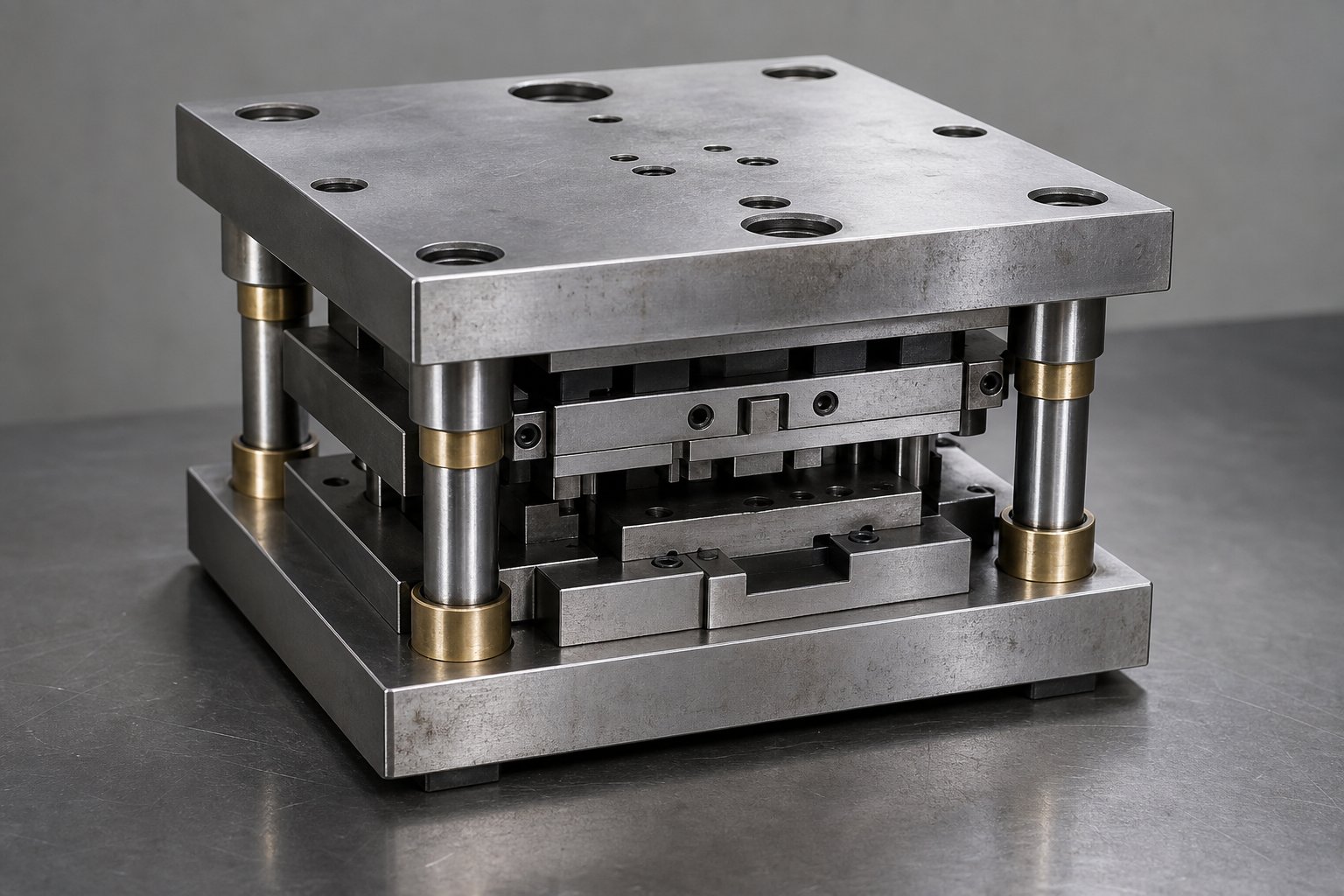
What Are Stamping Die Sets and Why They Matter
When you hear someone mention a stamping die set, they might be talking about the entire press die tooling package or just the structural framework that holds everything together. That distinction matters more than most people realize, especially if you are specifying or purchasing tooling for the first time.
A stamping die set is the precision-ground assembly of upper and lower die shoes, guide pins, and bushings that aligns and supports the cutting and forming components during metal stamping operations.
What a Stamping Die Set Actually Does
Think of die sets as the skeleton of your stamping operation. The upper and lower steel or aluminum plates (called die shoes) mount directly to the press ram and bolster. Guide pins and bushings connect these shoes, ensuring the top half travels straight down onto the bottom half every single stroke. Without that repeatable alignment, your metal stamping dies would drift, causing uneven cuts, premature wear, and potential press damage.
Die Set vs. Complete Stamping Die
A complete stamping die includes everything needed to produce a finished part: punches, die buttons, strippers, springs, and the metal die components that actually cut or form sheet metal. The die set is only the guiding framework those active components bolt into. You can swap different stamper dies in and out of the same set, as long as the footprint and tonnage requirements match. This modularity is what makes standard die sets so cost-effective for shops running multiple jobs on a single press.
Why Alignment Precision Matters
Guide pins in a quality die set are manufactured within 0.0001 in. of true position. That level of accuracy directly affects part tolerances, tool life, and operator safety. When alignment drifts even a few thousandths, punch-to-die clearance becomes uneven, burrs increase on one side, and cutting forces spike unpredictably. A well-made press die set absorbs those forces evenly and keeps die stamps tracking true, stroke after stroke, across millions of cycles.
The real payoff is consistency. Tight alignment reduces scrap, extends sharpening intervals, and protects the press ram from off-center loading that accelerates bearing wear. For high-volume operations, that translates directly into lower cost-per-part and fewer unplanned shutdowns.
Die Set Types and Configuration Selection
Every stamp die set configuration exists to solve a specific access-versus-rigidity tradeoff. The guide posts that keep your upper and lower shoes aligned also occupy physical space around the die area, and where you place them determines how material feeds in, how stable the assembly is under load, and what kinds of operations the set can handle. Choosing the wrong layout for your application means either fighting feed interference or accepting unnecessary deflection.
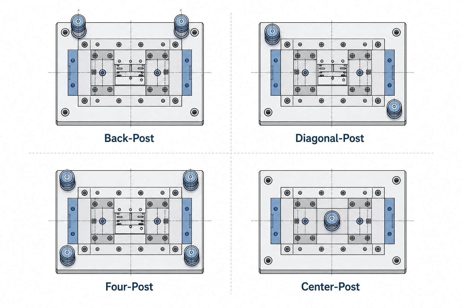
Die sets are commercially produced in several standard configurations, and suppliers like Danly die sets and other catalog manufacturers offer them ready to ship. The four primary layouts you will encounter are back-post, diagonal-post, four-post, and center-post. Each one earns its place in the catalog for distinct mechanical reasons.
Two-Post Die Sets and Strip Feed Access
Back-post die sets position both guide pins at the rear of the die area. This leaves the front and both sides completely open, giving you unobstructed strip feed access. If you are running a progressive tool die with coil stock feeding left-to-right, the back-post layout keeps posts out of the strip path entirely. That makes it the default choice for high-speed progressive stamping where any feed obstruction causes mis-hits and scrap.
The limitation? Two posts at the rear provide less torsional rigidity than configurations with posts spread across the die area. For light-to-medium gauge sheet metal die work and well-balanced cutting forces, that is rarely a problem. But if your forming die generates heavy off-center loads, a back-post set may allow enough angular deflection to affect part quality.
Four-Post Die Sets for Maximum Rigidity
When you need every thousandth of alignment held under heavy tonnage, four-post sets are the answer. A guide pin in each corner creates a rigid cage that resists deflection in every direction. Heavy blanking die operations on thick stock, tight-tolerance coining, and any press die set expected to handle asymmetric forces benefit from this layout.
The tradeoff is access. With posts on all four corners, strip feeding becomes more constrained. You will typically need to route material between posts, which limits maximum strip width relative to die area size. Four-post sets also cost more and weigh more, so they are harder to justify for short-run prototyping or simple single-station work. They earn their keep in die sets for press applications where rigidity directly translates to part accuracy and extended tool life.
Diagonal and Center-Post Configurations
Diagonal-post sets split the difference. By placing two guide pins on opposite corners, they maintain better rotational stability than a straight back-post arrangement while still leaving two sides open for feeding. Imagine you need side access for a secondary operation or strip feed clearance on one side but want more rigidity than a back-post set provides. That is exactly where diagonal configurations fit.
Center-post (sometimes called single-post or pedestal) sets use one large-diameter guide element at the center or near-center of the die. These are less common in production stamping and tend to appear in specialized applications or very small press die set configurations where a single robust guide is adequate for the load and precision requirements.
| Configuration | Number of Posts | Best Application | Rigidity Level | Feed Access |
|---|---|---|---|---|
| Back-Post | 2 (rear) | High-speed progressive stamping, coil-fed operations | Moderate | Excellent - front and sides open |
| Diagonal-Post | 2 (opposite corners) | Medium-duty work needing balanced access and stability | Moderate-High | Good - two sides open |
| Four-Post | 4 (all corners) | Heavy blanking, tight-tolerance coining, asymmetric loads | Maximum | Limited - feed between posts |
| Center-Post | 1 (center) | Small or specialized low-tonnage applications | Low-Moderate | Excellent - all sides open |
Selection comes down to three questions: How does material enter the die? How heavy and asymmetric are the stamping forces? And how tight are the part tolerances? For most production progressive work, a back-post set handles the job. When tonnage climbs or tolerances tighten, move to diagonal or four-post. The configuration you choose sets the foundation for everything mounted inside it, and that brings up the next critical decision: which components go into those shoe plates and how their individual specs affect the assembly's performance.
Core Components Inside Every Die Set
A die set configuration only matters if the individual stamping die components inside it are correctly specified and working together. Each part in the assembly has a single job, and when one element underperforms, the entire die assembly feels it through misalignment, accelerated wear, or inconsistent parts off the press. Here is what actually lives inside those shoe plates and why each piece earns its spot.
- Upper and lower die shoes - the mounting platforms that carry all active tooling and attach to the press ram and bolster.
- Guide pins (posts) - hardened steel cylinders that align the upper shoe to the lower shoe every stroke.
- Guide bushings - precision-ground sleeves that receive the guide pins with controlled clearance or preload.
- Die plate - the machined working surface where punching die details, buttons, and forming sections are mounted.
- Shank holder - a cylindrical adapter that centers the upper shoe in the press ram bore for single-station tools.
Upper and Lower Die Shoes
Die shoes are the structural foundation of the entire assembly. The lower shoe bolts to the press bolster and carries the die plate, die buttons, and any forming details. The upper shoe clamps to the ram and holds the die punches, retainers, and stripper system. Both shoes are typically made from medium-carbon steel or pre-hardened alloy, ground flat and parallel to within a few tenths of a thousandth. That parallelism matters because any bow or taper in the shoe surface translates directly into uneven cutting forces across the press die punch faces.
Shoe thickness is selected based on tonnage. Thin shoes flex under heavy loads, throwing alignment off at the worst possible moment, right at the bottom of the stroke. Heavier blanking or coining operations demand thicker plates; lighter piercing work can get by with thinner, lighter shoes that reduce overall die weight.
Guide Pin and Bushing Types Explained
Guide pins are ground to tolerances within 0.0001 in. and come in two fundamental styles: friction (plain bearing) and ball bearing. The choice between them shapes how the die assembly performs at speed, under side load, and during maintenance.
Ball-bearing guide pins ride on a series of precision balls contained in an aluminum cage. They operate in a preloaded or "negative clearance" condition, meaning the pin-and-bearing assembly is actually slightly larger than the bushing bore. This eliminates play, reduces friction, and makes separating die halves easy. They are the industry standard for high-speed progressive stamping where heat buildup from friction is unacceptable. One caution: excessive side thrust can cause ball tracking, physical grooves worn into the post or bushing by overloaded bearings.
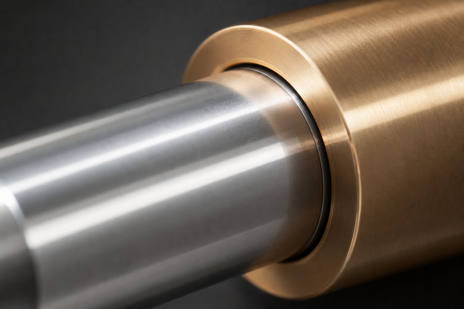
Bronze bushings pair with plain friction pins and handle heavy side loads well because contact is distributed across a broad surface rather than concentrated at ball-contact points. Solid aluminum-bronze or bronze-plated steel bushings are common, and they work best at moderate press speeds where some friction is tolerable in exchange for load capacity.
Self-lubricating bushings embed graphite plugs directly into the bronze matrix, delivering continuous dry lubrication without external grease. They reduce maintenance intervals in environments where re-lubrication schedules are difficult to enforce or contamination is a concern.
Guide pin mounting also matters. Press-fit pins are permanently installed in the shoe, which adds rigidity but makes replacement harder. Demountable pins use a mechanical lock (typically a cap screw or collar) and can be removed without pressing, simplifying maintenance and die storage. For engineers sourcing custom components where bushing type, pin diameter, and mounting style all interact with die structure and clearance requirements, suppliers like YICHEN offer collaborative engineering support tailored to design-heavy decisions like these.
Supporting Components and Their Roles
Beyond shoes, pins, and bushings, several smaller components complete the assembly. Shank holders center the upper shoe in the press ram for single-station dies where precise ram-to-die alignment is critical. Backing plates sit between die punch heads and the shoe face, distributing impact loads so hardened punch shanks do not peen into softer shoe steel over millions of cycles. Die retainers lock punches and buttons at exact positions within the die plate, and springs (mechanical or nitrogen) provide stripping force to lift the workpiece off the tooling after each stroke.
Every one of these stamping die components interacts with the others. A ball-bearing bushing paired with a shoe that is too thin will track perfectly in alignment but flex under load, defeating the purpose of precision guidance. Getting the combination right means thinking beyond individual specs and considering how the full system behaves under your actual tonnage, speed, and material conditions, which leads directly to the question of matching your die set to the press it will run in.
How to Match Die Sets to Your Press
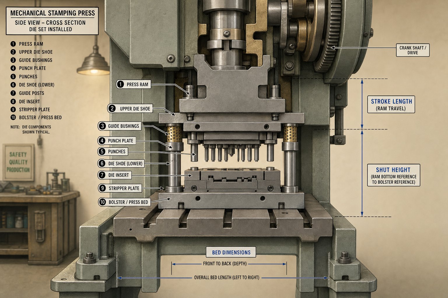
A perfectly specified die set is useless if it does not physically and mechanically fit the press it is intended for. The relationship between press and die is an integrated system, and getting the match wrong leads to anything from an inability to install the tool to catastrophic overloading during production. The critical parameters you need to reconcile are tonnage capacity, bed dimensions, shut height range, and stroke length.
Press Tonnage and Die Set Load Capacity
Every stamping operation generates a calculable force based on cut perimeter, material thickness, and tensile strength. Your press must exceed that calculated tonnage with a safety margin of 20 to 30 percent to account for material variation and progressive tool wear. But tonnage is not just about whether the press can push hard enough. It also dictates die shoe thickness. Higher forces demand thicker plates to resist deflection, and thicker plates add weight. That combined die set weight must remain well within the ram's lifting capacity, or the press struggles to retract the upper half cleanly on the upstroke.
For punch press dies running at high speeds, even small imbalances between required force and available capacity compound with every stroke. Over-tonnage stalls a die stamping press or cracks the frame; under-specifying the die set's shoe thickness lets it flex, throwing alignment off and chipping punches.
Bed Size and Shut Height Matching
The die set footprint must fit within the press bed area with room left for clamps on all sides. Strip width, part geometry, and station count in progressive tools determine the minimum footprint, but the bolster sets the maximum. Sounds simple, but the vertical dimension catches more engineers off guard. Shut height is the distance from the bolster top surface to the slide bottom when the ram is at its lowest point with adjustment fully extended. Your die height (total closed height of the assembly) must fall within the press's adjustable shut height range.
If the die is too tall, it physically cannot close. If it is too short, spacer plates or parallels can make up the gap, but only within the press's adjustment travel. Keep in mind that die shoes lose height over time as they are reground, so initial shut height should sit toward the upper end of the adjustment window to allow for future maintenance.
Mechanical vs. Hydraulic Press Considerations
Press type fundamentally changes how you approach die set selection. A mechanical press delivers peak tonnage only near the bottom of its stroke, just a few millimeters above bottom dead center. That means shut height control is critical. If your punch press die set closes even slightly too high, the press cannot deliver full rated force, and part quality suffers. Mechanical presses also have a fixed stroke length dictated by crank geometry, so your die must be designed around that constraint.
A hydraulic press die set has more breathing room. Hydraulic systems deliver full tonnage anywhere in the stroke and offer adjustable stroke length, making them more forgiving on shut height tolerances. Hydraulic press dies also avoid the high-impact shock loading of mechanical systems, which can allow slightly thinner die shoes for equivalent tonnage in forming applications. However, cycle times are slower, so if you are pairing a die set with a hydraulic press for deep drawing or complex forming, plan for longer strokes and controlled ram speeds rather than high-speed blanking.
When you are ready to pair a die set to your press, work through these steps in order:
- Record press specifications from the machine manual: rated tonnage, tonnage rating point (for mechanical presses), bed dimensions, maximum and minimum shut height, stroke length, and strokes per minute.
- Calculate total required stamping force for all cutting and forming stations, then add a 20 to 30 percent safety margin.
- Determine the minimum die set footprint based on strip width, part size, and number of stations, ensuring it fits within bed dimensions with clamping clearance on all sides.
- Select shoe thickness appropriate to the calculated tonnage and verify that the resulting die height falls within the press's adjustable shut height range.
- Confirm that total die set weight (shoes, pins, bushings, and mounted tooling) does not exceed ram lifting capacity.
- Verify stroke length is sufficient for material feed, part clearance, and safe ejection of finished pieces or scrap.
- For mechanical presses, confirm the tonnage rating point is above the material thickness to ensure full force is available when punch dies for press contact the workpiece.
Following this sequence prevents the common mistake of specifying a die set that looks right on paper but cannot physically run in the intended machine. Every parameter feeds into the next, and missing even one, especially the shut height or tonnage rating point, turns a perfectly machined hydraulic press die set or mechanical setup into an expensive shelf ornament. Getting these numbers locked down early also simplifies the next decision: choosing from standard catalog sizes or stepping into custom dimensions.
Die Set Sizing Conventions and Standards
Matching your die set to the press is only half the equation. The other half is choosing a set of die dimensions that give your active tooling enough room to work while keeping the overall footprint efficient. Standard die sets follow well-established sizing conventions that balance plate area, thickness, and guide pin proportions. Understanding these conventions helps you decide when a catalog size fits your application and when you need to go custom.
Standard Die Set Dimensions and Plate Thickness
Industry catalogs, including those from established suppliers like Danly die set lines and other manufacturers, offer standard sizes starting as small as 6 x 6 inches for miniature stamping work and scaling up through common mid-range dimensions like 12 x 12, 18 x 24, and 24 x 36 inches. Large die sets extend well beyond these, with some manufacturers producing stock die platforms exceeding 60, 80, or even 120 inches for automotive panel work and heavy structural stamping.
Plate thickness scales with expected tonnage. A small 6 x 6 set running light piercing loads might use shoes as thin as 1 inch, while a large die platform handling several hundred tons of blanking force needs shoes 4 inches thick or more to resist deflection. The general principle: thicker shoes distribute force more evenly across the bolster and ram face, reducing localized stress that leads to fatigue cracking over millions of cycles.
| Die Set Size (in.) | Typical Shoe Thickness (in.) | Typical Tonnage Range | Common Application |
|---|---|---|---|
| 6 x 6 to 8 x 8 | 1.0 - 1.5 | 5 - 30 tons | Small connectors, terminals, micro-stamping |
| 10 x 12 to 14 x 18 | 1.5 - 2.5 | 30 - 100 tons | Mid-size brackets, clips, progressive dies |
| 18 x 24 to 24 x 36 | 2.5 - 3.5 | 100 - 300 tons | Larger progressive dies, heavy-gauge blanking |
| 30 x 48 to 48 x 72 | 3.5 - 5.0 | 300 - 800 tons | Automotive structural parts, appliance panels |
| 60 x 96 and above | 5.0 - 8.0+ | 800 - 2,000+ tons | Large automotive panels, heavy structural stampings |
These are guidelines, not absolutes. A metal die set carrying a blank die with concentrated punch loads at center may need thicker shoes than the tonnage alone suggests, because bending moment increases with unsupported span. Conversely, a uniformly distributed cutting pattern across many small punches may tolerate thinner shoes at the same total tonnage.
Sizing for Progressive vs. Single-Station Dies
Single-station dies, whether compound or combination tools, need only enough die area for the part footprint plus clearance for scrap channels, mounting hardware, and guide elements. Sizing these is relatively straightforward: take the maximum part dimension in each direction, add material for carrier strips or scrap bridges, and select the nearest standard die size that accommodates everything with room for clamps.
Progressive dies demand a different calculation. Each station occupies a slice of the die length equal to the feed pitch, and the total number of stations multiplied by pitch determines the minimum die length. A 12-station progressive with 2-inch pitch needs at least 24 inches of working length before you even account for lead-in and tail-end scrap stations. Strip width plus carrier material sets the minimum die width.
As progressive die experts note, large progressive dies require robust carrier and tie bars to keep the strip stable through many stations, and that carrier width adds to the overall die footprint. The more trim and form stations required, the more strip support material you need, and the wider and longer the die set becomes.
Guide pin diameter and length also scale with die size. Smaller standard die sets typically use 1-inch to 1.5-inch diameter pins, while sets in the 24 x 36 range and above move to 2-inch or larger posts. Pin length must provide adequate engagement at full open height, meaning longer strokes require longer pins, which in turn demand larger pin diameters to resist bending under any residual side loads. A pin that is too slender relative to its unsupported length will deflect elastically, defeating the purpose of precision guidance.
When Standard Sizes Fall Short
Standard catalog sizes cover a wide range of applications, and for good reason. They are manufactured in volume, which keeps costs down and lead times short. Industry experience confirms that purchasing standard sets from specialty fabricators who leverage economies of scale nearly always beats the cost of building one-off sets in-house.
Still, some jobs push beyond what a standard die can accommodate. You might encounter situations like:
- Part geometry that requires an unusual length-to-width ratio not available in catalogs.
- Progressive dies with high station counts that exceed standard lengths.
- Non-standard guide pin placement dictated by feed or tooling interference.
- Oversized blanks for automotive or appliance panels that push into large die territory above 60 inches.
- Custom shoe thicknesses needed for extreme tonnage or unusual press shut height constraints.
In these cases, a custom die set becomes the practical choice. Custom does not necessarily mean expensive or slow. Many suppliers machine custom dimensions from pre-ground plate stock using CNC equipment, keeping turnaround reasonable. The decision comes down to whether forcing your tooling into the nearest standard footprint compromises performance. If you are cramming stations too close together, eliminating necessary scrap clearance, or undersizing shoes to fit a catalog dimension, the cost of scrap and maintenance will quickly exceed the premium for a custom metal die set.
One middle ground worth considering: buying a standard set and modifying it. Some shops purchase catalog die sets and then add machined pockets, non-standard pin locations, or additional mounting features on their own CNC equipment. This hybrid approach, sometimes called DIY in the industry, can shorten timelines while still delivering a set sized correctly for the application.
Sizing sets the physical boundaries of your tooling, but physical dimensions alone do not guarantee performance. The precision to which those dimensions are held, the tolerances on pin-to-bushing fit, shoe parallelism, and surface finish, determines whether your stamped parts actually meet print specifications cycle after cycle.
Tolerances and Precision in Die Set Performance
You can select the right configuration, size the shoes perfectly, and match every press parameter, but if the tolerances on your die set are loose, your stamped parts will never hold tight dimensions. Precision in die tooling starts at the framework level. The guide system and shoe surfaces set an absolute ceiling on how accurate your finished parts can be, no matter how well the active punches and die buttons are ground.
Die set precision is the ceiling for stamped part precision. No punch or die button can deliver tolerances tighter than the framework guiding it.
Guide Pin Clearance and Its Effect on Part Quality
The running clearance between a guide pin and its bushing directly determines how much the upper die half can shift laterally relative to the lower half during each stroke. In a plain-bearing system, that clearance is deliberately engineered, typically ranging from 0.0002 in. to 0.0008 in. depending on pin diameter and application. Ball-bearing systems operate differently, running in a preloaded condition with negative clearance ranging from 0.0001 to 0.0021 in., effectively eliminating free play between the upper and lower halves.
Why does this matter for your parts? Imagine a precision die and stamping operation where punch-to-die clearance is set at 0.001 in. per side. If the guide system allows 0.0005 in. of lateral shift, that clearance becomes uneven: 0.0005 in. on one side and 0.0015 in. on the other. The result is inconsistent burr height, uneven edge quality, and accelerated wear on one side of the cutting tooling die. For tight-tolerance work, the guide pin-to-bushing clearance must be a fraction of the working punch-to-die clearance to keep forces balanced.
Parallelism and Perpendicularity Tolerances
Shoe surface parallelism is the second critical tolerance. Both the upper and lower shoe faces must be ground flat and parallel to each other within a few tenths of a thousandth of an inch. If the upper shoe tilts even slightly relative to the lower, punches on one side of the die contact the workpiece before punches on the other side. That staggered engagement creates unequal cutting forces, premature punch wear, and dimensional variation across multi-station progressive tools.
Perpendicularity of guide pins to the shoe face is equally important. A pin that leans even 0.001 in. over its working length introduces a progressive misalignment that worsens as the stroke increases. For precision dies running in high-speed applications, this angular error multiplies with every inch of stroke travel. Die machining processes typically hold pin perpendicularity to within 0.0002 in. per inch of pin length on quality sets, though machining dies to tighter specs is possible at additional cost.
Surface finish on shoe faces affects both parallelism and mounting stability. A rough-ground surface allows die plates and backup plates to shift microscopically under repeated impact loading. Most steel stamping dies specify shoe faces ground to 16 microinches Ra or better, which provides enough friction for secure mounting while remaining flat enough for accurate measurement and shimming.
Precision Classes for Different Applications
Not every job needs the tightest possible tolerances, and tighter always costs more. The general industry approach divides precision die sets into classes based on the accumulated tolerances across all critical features: pin clearance, parallelism, perpendicularity, and surface finish. Standard-class sets suit general blanking and forming where part tolerances are generous. Precision-class sets serve close-tolerance work like connector stamping, fine-blanking, or any application where total system clearance must stay below a few tenths.
Here is where operating conditions complicate the decision. During a production run, friction and forming forces generate heat. Thermal expansion in the guide pins, bushings, and shoe plates changes the working clearances you so carefully specified at room temperature. A precision die set running at 600 strokes per minute in a high-speed progressive application can see guide system temperatures rise 30 to 50 degrees Fahrenheit above ambient. That heat expands the pins faster than the bushings (steel pins in bronze bushings), gradually closing running clearance. If initial clearance is too tight, the system binds. If you compensate by opening clearance at room temperature, you lose precision during cold startup.
The practical solution: select your precision class based on worst-case operating temperature, not shop-floor ambient. Factor in your expected stroke rate, material being stamped, and lubrication system. Ball-bearing guide systems handle thermal variation better because their preload accommodates slight dimensional changes without binding. Plain-bearing bronze bushings need more initial clearance headroom to account for thermal closure, which is why they are typically specified for moderate-speed die equipment rather than high-speed precision work.
Ultimately, tolerance selection is a cost-benefit decision. Every half-tenth you tighten on the die set adds grinding time, inspection steps, and material cost. But every half-tenth you leave loose becomes part variation, scrap, and shortened tool life downstream. The right balance depends on your part print, your production volume, and how much variation your downstream processes can absorb. That balance also shifts over time as components wear, which raises the question of how to monitor that wear and decide when a die set has exceeded its useful tolerance envelope.
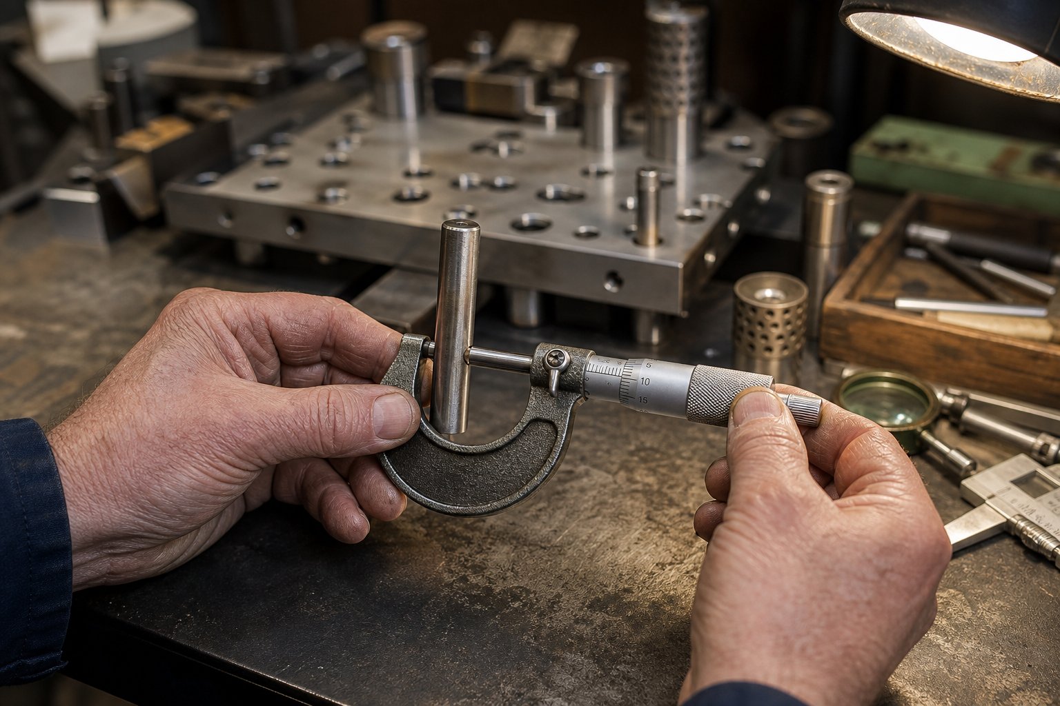
Maintenance and Knowing When to Replace Die Sets
Tolerances that were perfect on day one do not stay perfect forever. Every stroke adds microscopic wear to guide pins, bushings, and die shoe surfaces. Left unchecked, that wear creeps past your tolerance envelope and quietly degrades part quality long before anything fails catastrophically. A proactive inspection and maintenance program is what separates a die shop that catches problems early from one that discovers them in scrap bins.
Inspection Points and Wear Measurement
When you pull a die set for scheduled maintenance, these are the checkpoints that matter most. Keep this list posted near your die equipment storage area so technicians hit every item consistently:
- Guide pin diameter - Measure at multiple points along the working length with a micrometer. Wear typically concentrates where the bushing contacts the pin at the working level. A reduction of more than 0.0005 in. from nominal warrants replacement.
- Bushing bore diameter - Use a bore gauge to check ID at the top, middle, and bottom. Oval or tapered wear patterns indicate misalignment or excessive side loading.
- Pin-to-bushing clearance - Calculate from your pin and bushing measurements. When clearance exceeds twice the original specification, part accuracy is compromised.
- Ball bearing cage condition - Look for blue discoloration or damaged set screw dog points, both indicators of cage creep and skidding bearings.
- Die shoe flatness and parallelism - Sweep both shoe faces with an indicator on a surface plate. Check for dishing, warpage, or localized low spots from repeated impact loading.
- Shoe surface condition - Inspect for galling, scoring, or fatigue cracking around pin bores and die clamp mounting areas.
- Guide pin perpendicularity - With the pin installed, indicate along its length. Any lean exceeding 0.0002 in. per inch signals a worn bore or damaged shoe.
- Tracking marks on pins or bushings - Light surface lines are normal, but grooves that indent the working surface indicate excessive side loads or improper bushing installation.
Lubrication and Preventive Maintenance
Lubrication requirements differ sharply by bushing type, and using the wrong lubricant is as damaging as using none at all. For ball-bearing guide systems, grease is not recommended. Because these die components operate with negative clearance, grease traps contaminants that get ground into the rolling contact surfaces, causing flat spots on bearings and accelerated wear. Instead, use a refined mineral oil with extreme-pressure additives and rust inhibitors, viscosity around 290/340 SSU at 100 degrees F.
Bronze plain-bearing bushings, on the other hand, tolerate heavier lubricants and benefit from periodic greasing, especially under heavy tonnage loads. Self-lubricating graphite bushings require no external lubrication under normal conditions, but periodic cleaning of the graphite pockets prevents buildup of stamping debris that blocks the lubricant path.
Maintenance intervals depend on production volume. High-speed progressive operations running millions of strokes per month need inspection every 250,000 to 500,000 hits. Lower-volume work with moderate die maker tools usage can stretch to scheduled quarterly checks. When setting die maintenance intervals, err on the shorter side until you establish a baseline wear rate for each specific tool.
End-of-Life Indicators and Replacement Timing
Every die set eventually reaches a point where maintenance no longer restores acceptable performance. Recognizing that threshold prevents you from pouring labor into a framework that cannot hold tolerance regardless of how much attention it receives. Watch for these signals:
- Guide pin wear beyond regrind - Pins worn more than 0.001 in. undersize cannot be restored. Replacement is the only option.
- Bushing bore enlargement beyond tolerance class - When bore diameter grows past the maximum allowable clearance even with a new pin installed, the bushing seat in the die shoe may also be damaged.
- Die shoe warpage exceeding regrind capacity - Shoes can be reground to restore flatness, but each regrind removes material and reduces shut height. Once a shoe is ground below its minimum functional thickness, it flexes under load and cannot be recovered.
- Fatigue cracking around pin bores or die clamps mounting holes - Cracks propagate under cyclic loading. A cracked shoe is a safety hazard and must be retired immediately.
- Persistent cage creep despite corrective action - If bumpers, preload adjustments, and component resizing fail to resolve cage creep, the overall die set geometry may have shifted beyond correction.
- Repeated tracking on one side only - Unilateral tracking that returns after pin and bushing replacement points to bore misalignment in the shoe itself, a condition that typically means the shoe plate is no longer serviceable.
Replacing a worn die set is not a failure. It is a planned transition that protects part quality and press safety. The real cost of running past end-of-life is not the set itself but the scrap, rework, and unplanned downtime that accumulate when alignment can no longer be maintained. Knowing when to retire a set also informs how you specify its replacement, and getting that specification right from the start is what separates a quick reorder from a drawn-out engineering exercise.
How to Specify and Order the Right Die Set
Retiring a worn die set only saves you if the replacement is specified correctly from the start. Vague purchase orders lead to back-and-forth emails, mismatched dimensions, and lead time surprises that stall production. The difference between a smooth reorder and a frustrating procurement cycle comes down to how completely you communicate your requirements upfront.
Information You Need Before Ordering
Before you contact any stamping dies manufacturer or pull up a catalog, gather every parameter that affects your die set selection. Missing even one detail, like shut height range or bushing preference, forces the supplier to guess or come back with questions that add days to your timeline.
Use this specification checklist when requesting quotes for metal stamping die sets:
- Press specifications - rated tonnage, tonnage rating point (mechanical presses), bed dimensions, minimum and maximum shut height, stroke length, and strokes per minute.
- Die set footprint - required length and width based on strip layout, station count, and clamping clearance.
- Shoe thickness - based on tonnage calculations and shut height constraints. Specify both upper and lower if they differ.
- Guide pin configuration - back-post, diagonal, four-post, or center-post, along with pin diameter and length requirements.
- Bushing type - ball-bearing, bronze plain-bearing, or self-lubricating, based on speed, load, and maintenance considerations.
- Pin mounting style - press-fit or demountable, and whether pins mount in the upper or lower shoe.
- Material and hardness - shoe material grade, surface hardness if required, and any heat treatment specifications.
- Tolerance class - standard or precision, with specific callouts for parallelism, perpendicularity, and pin-to-bushing clearance.
- Part and process details - workpiece material, thickness, geometry complexity, and expected production volume over the die set's life.
- Special requirements - non-standard pin locations, oversized format, additional machined pockets, or custom mounting features.
Having this list complete before you pick up the phone eliminates the most common source of ordering delays. It also lets you compare quotes on equal terms across multiple die manufacturers, because everyone is pricing the same specification.
Standard Catalog vs. Custom-Engineered Die Sets
Standard catalog sets ship faster and cost less, sometimes dramatically so. Industry experience from Anchor Danly confirms that specialty fabricators leveraging economies of scale and production expertise consistently undercut the cost of building equivalent sets in-house. For straightforward applications where your footprint, tonnage, and configuration match a catalog offering, there is no reason to go custom.
Custom-engineered die sets become necessary when standard dimensions compromise your tooling layout. Maybe you need a non-standard length-to-width ratio for a high-station progressive die, unusual pin placement to clear a feed system, or shoe thicknesses outside catalog norms. Custom die manufacturing typically adds two to six weeks over standard lead times depending on complexity, but the result is a set that fits your application without compromise.
A middle path exists as well. Some engineers buy a standard set and machine additional features in-house, shortening lead time while still getting a custom metal stamping die footprint. This hybrid approach works when the modifications are limited to pockets, dowel holes, or mounting features that do not affect guide system precision.
Evaluating Suppliers for Your Application
Not every die manufacturer offers the same depth of capability. When evaluating stamping die manufacturers, look beyond price and lead time to assess three factors that determine long-term value:
- Precision capabilities - Can the supplier hold the tolerance class you need? Ask about their grinding equipment, inspection methods, and whether they provide dimensional reports with shipment. Leading suppliers operate under ISO 9001:2015 systems and perform in-process dimensional checks, not just final inspection.
- Material quality and traceability - Reputable suppliers use certified tool steels with documented heat treatment processes. Ask whether material certifications accompany the finished set.
- Engineering support - This is where the gap between catalog vendors and true manufacturing dies partners becomes clear. A supplier that simply machines what you draw is fine for standard orders. But for design-heavy applications involving complex die structure, tight clearance requirements, or challenging material flow, you need collaborative engineering. Suppliers like YICHEN connect tooling engineers to custom stamping die solutions with particular strength in design-intensive decisions around die structure, clearance optimization, and material flow, the kind of support that prevents costly redesigns after first article trials.
Price matters, but a cheap set that fails after a fraction of its expected life costs far more in downtime and replacement than a quality set from a capable supplier. Evaluate total cost of ownership: initial price plus maintenance plus expected service life plus the scrap risk from running marginal precision. That calculation almost always favors the supplier with stronger engineering support and tighter process control, especially for production tooling expected to deliver millions of parts over its lifetime.
Frequently Asked Questions About Stamping Die Sets
1. What is the difference between a die set and a complete stamping die?
A die set is the structural framework consisting of upper and lower die shoes, guide pins, and bushings that provides precision alignment. A complete stamping die includes the die set plus all active tooling such as punches, die buttons, strippers, and springs that actually cut or form the metal. You can swap different active tooling in and out of the same die set as long as footprint and tonnage requirements match, which makes standard die sets cost-effective for shops running multiple jobs.
2. How do I choose between a two-post and four-post die set?
The choice depends on three factors: how material feeds into the die, how heavy the stamping forces are, and how tight your part tolerances need to be. Two-post back-post sets leave the front and sides open for unobstructed strip feeding in progressive dies but offer less torsional rigidity. Four-post sets provide maximum rigidity for heavy blanking or tight-tolerance coining but limit strip width since material must feed between corner posts. For most high-speed progressive work, back-post configurations handle the job well. When tonnage increases or tolerances tighten, move to four-post.
3. What are ball-bearing bushings vs. bronze bushings in die sets?
Ball-bearing bushings use precision balls in a cage to guide the pin with negative clearance (preloaded fit), eliminating free play and reducing friction. They suit high-speed progressive stamping where heat from friction is unacceptable. Bronze bushings operate as plain bearings with distributed surface contact, handling heavy side loads better than ball bearings. They work best at moderate speeds where some friction is acceptable in exchange for greater load capacity. Self-lubricating bushings with embedded graphite plugs offer a third option for environments where regular re-lubrication is impractical. Suppliers like YICHEN provide engineering support to help select the right bushing type for specific die structure and clearance requirements.
4. How do I match a die set to my stamping press?
Start by recording your press specs: rated tonnage, bed dimensions, shut height range, and stroke length. Calculate total stamping force with a 20-30% safety margin, then determine minimum die set footprint based on strip width and station count. Select shoe thickness appropriate to your tonnage, verify the resulting die height fits within the press shut height range, and confirm total weight stays within ram lifting capacity. For mechanical presses, also verify the tonnage rating point is above your material thickness so full force is available at the moment of contact.
5. When should a stamping die set be replaced?
Replace a die set when guide pin wear exceeds 0.001 in. undersize and cannot be restored by regrinding, when bushing bore enlargement pushes clearance beyond twice the original specification even with new pins, when shoe warpage exceeds regrind capacity and shoes fall below minimum functional thickness, or when fatigue cracks appear around pin bores or mounting holes. Persistent one-sided tracking that returns after component replacement also signals that the shoe plate geometry has shifted beyond correction and the set should be retired.


