


What Are Stamping Die Punches and Why They Matter
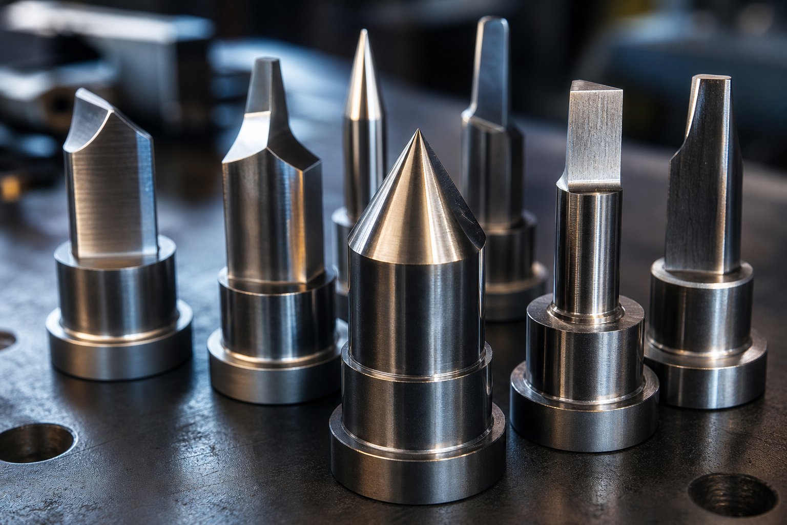
Stamping die punches are the hardened steel tools that physically contact and transform sheet metal during press operations. Think of the punch as the male component of a punch and die set: it descends into a matching female opening (the die block) to shear, form, or displace material into a finished shape. Every hole, notch, and contour in a stamped part starts with the cutting edge of a die punch doing its job under tonnage.
Punches are just one piece of a larger system. Strippers hold the sheet flat and pull it off the punch during retraction. Pilots locate the strip precisely from station to station. Lifters raise the material between strokes so it can advance. Each of these stamping die components plays a supporting role, but the punch itself does the primary work of material transformation.
What a Stamping Die Punch Actually Does
When the press ram drives the punch downward, the cutting edge initiates a fracture on the top surface of the sheet. Simultaneously, the die block's edge initiates a matching fracture from the bottom. With correct clearance, these two fracture lines meet in the middle, producing a clean separation with minimal burr. The result is a three-zone cut edge: a slight rollover at the top, a smooth burnished band where shearing occurred, and a rougher fracture zone where the crack propagated through the remaining thickness. This shearing mechanism is what makes metal stamping dies so efficient at producing thousands of parts per hour with repeatable quality.
Where Punches Fit Within the Die Assembly
To understand how a punch operates, you'll want to see where it lives inside the metal die assembly. Here are the key components from top to bottom:
- Upper shoe - the top plate that mounts to the press ram and carries all upper-half tooling
- Punch plate (retainer) - holds die punches in fixed position relative to each other
- Punch - the working tool that contacts the sheet metal
- Stripper - clamps material flat and strips it off the punch during retraction
- Die block - contains the mating openings that provide the opposing cutting edge
- Lower shoe - the bottom plate that bolts to the press bolster
The die shoes provide structural rigidity for the entire assembly, and any deflection or misalignment at that level cascades directly into punch performance. That relationship between the assembly and the cutting tool is exactly why punch quality drives everything downstream: part dimensional accuracy, edge condition, burr height, and ultimately how many hits you get before the tool needs attention. A worn or poorly designed punch does not just produce bad parts. It accelerates wear on every adjacent component and eats into your production uptime.
The sections ahead break down each variable that determines whether your punches last or fail early, starting with the full range of punch types and the specific jobs they handle.
Complete Taxonomy of Punch Types by Function
Not every punch does the same job. A piercing punch that creates bolt holes in a bracket has almost nothing in common with a coining punch that compresses material to hold a tight tolerance. Knowing which category your operation falls into is the first step toward choosing the right metal punch tool for the application, and it directly impacts how long that tool will last in production.
Cutting Punches for Material Separation
Cutting punches share one goal: separating material. The differences come down to what you keep, what you discard, and where the cut happens relative to the part edge.
- Piercing punches create holes by driving a slug completely through the sheet. The perforated sheet is the product; the slug is scrap. This is the most common metal hole punch operation in progressive dies, handling everything from fastener clearance holes to ventilation patterns.
- Blanking punches cut the entire outer profile of a finished part in one stroke. Here the slug becomes the product and the remaining strip is waste. Blanking demands higher tonnage than piercing because the cut perimeter is typically much larger.
- Notching punches remove material from the edge of a strip or part. Because cutting occurs on only one side, these punches experience unbalanced lateral forces and often require a heel block for support.
- Lancing punches make partial cuts that form tabs or louvers without fully separating material. The connected edge bends over the die opening, so the punch geometry combines a shear angle with a forming radius.
- Trimming punches remove excess flange material from previously formed or drawn parts, cleaning up contours to final dimensions.
The force profile differs significantly across these types. A blanking punch engages the full cut perimeter simultaneously, producing peak tonnage in one instant. A lancing punch, by contrast, progressively shears and bends, distributing load over more of the stroke. These differences influence punch tooling decisions around steel grade, shear angles, and press capacity.
Non-Cutting Punches for Forming and Alignment
Not every puncher for metal actually cuts. Some punches shape material or simply locate it for downstream operations.
Pilot punches enter pre-existing holes in the strip to align it precisely before cutting begins at each precision punch station. They feature tapered or radiused noses and are typically ground slightly undersize (around 0.001 inches smaller than the locating hole) to avoid sticking during entry.
Forming punches bend, draw, or emboss material without full separation. Their working surfaces are contoured rather than sharp-edged, and they rely on controlled material flow rather than fracture mechanics.
Coining punches apply extreme localized pressure to compress material into a precise cavity, achieving tight tolerances on thickness or surface detail. Because the material is fully constrained, coining forces can be five to ten times higher than standard forming loads for the same contact area.
| Punch Type | Primary Function | Typical Geometry | Common Applications |
|---|---|---|---|
| Piercing | Create holes (slug is waste) | Round, oblong, or shaped with flat or sheared face | Fastener holes, vent patterns, electrical knockouts |
| Blanking | Cut finished part outline (slug is product) | Contoured profile matching part perimeter | Washers, laminations, brackets |
| Notching | Remove material from strip edge | Open-sided with heel for lateral support | Tab relief, corner cutouts, strip progression |
| Lancing | Partial cut to form tabs or louvers | Shear angle plus forming radius on connected edge | Louvers, heat-sink fins, locking tabs |
| Trimming | Remove excess material from formed parts | Contoured to match final trim line | Drawn cup flanges, formed bracket edges |
| Pilot | Locate strip for station accuracy | Tapered or bullet-nose, slightly undersize | Progressive die alignment at every station |
| Forming | Bend, draw, or emboss without separation | Contoured working surface, generous radii | Channel bends, shallow draws, embossed logos |
| Coining | Compress material for tight tolerances | Flat or engraved face, heavy cross-section | Thickness control, fine detail, bearing surfaces |
Specialty and Compound Punch Designs
When a single station needs to accomplish more than one operation, compound punch designs combine multiple functions into a single tool. A classic example: blanking the outer contour while simultaneously piercing internal holes in one press stroke. This approach delivers exceptional positional accuracy between features because both cuts happen in the same closure, but it concentrates load and limits available space for robust cross-sections.
Beyond compound configurations, you will encounter headed versus headless designs. Headed punches use a shoulder or flange to retain them in the punch plate, making replacement straightforward. Headless punches are secured by a backing plate or ball-lock retainer, allowing tighter spacing in dies with dense hole patterns. Stepped punches produce multi-diameter holes in a single hit, with each diameter ground to a different length along the tool body. They reduce the need for secondary operations but require precise grinding to maintain concentricity between steps.
Operations like punch and flare, where a hole is pierced and then expanded outward in a subsequent station, rely on pairing a standard sheet metal punch with a dedicated flaring tool downstream. Understanding which punch category applies to each station helps you specify the right geometry, material, and coating before problems show up on the press floor.
Geometry is what separates a punch that runs efficiently from one that wears prematurely or produces marginal parts. The next section breaks down exactly how point styles, shear angles, and back taper influence cutting forces and edge quality at the microscopic level.
Punch Geometry That Controls Force and Cut Quality
Two punches made from the same steel, run at the same speed, in the same press can deliver wildly different results. The difference is geometry. The shape of the punch face, the angle ground into it, and the relief behind its cutting edge determine how much force the press needs to punch a hole in metal, how clean the resulting edge looks, and how many hits the tool survives before resharpening.
Point Styles and Their Effect on Cutting Force
Imagine pressing a flat cookie cutter through dough versus tilting it so one side bites in first. That same principle applies when a press die punch contacts sheet metal. The geometry of the punch face controls how much material engages the cutting edge at any given instant during the stroke.
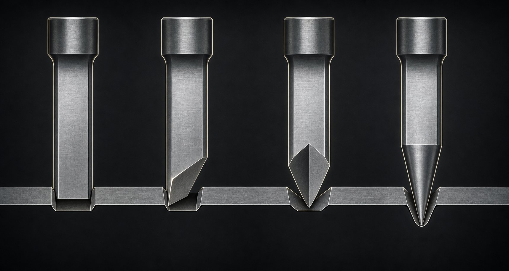
Flat-face punches engage the entire cut perimeter simultaneously. All the shearing happens in one instant, producing the highest peak tonnage but also the cleanest, most symmetrical hole. This is the baseline for any sheet metal punch hole operation.
Single-shear (beveled) punches angle the face so one side contacts the sheet first and the cut progresses across the diameter. Research on DP and AHSS grades shows a beveling angle between 3 and 6 degrees can reduce maximum piercing force by more than 50%. The trade-off is a slight lateral thrust that must be absorbed by the stripper or guide system.
Double-shear (roof-top) punches feature a peak along the center, so the cut initiates at the middle and spreads outward in both directions simultaneously. Studies on martensitic steel with 1400 MPa tensile strength have shown up to an 80% reduction in punching force compared with a flat face, along with a significant drop in snap-through reverse tonnage. Because the lateral forces balance on either side of the ridge, there is minimal side thrust on the tool.
Whisper-point (conical) punches use a tapered tip, similar in profile to a hex punch nose, to initiate contact at a single point and progressively expand the cut outward. They produce the quietest operation in thin materials and dramatically reduce snap-through shock, making them useful in high-speed applications where noise and press fatigue matter.
The underlying principle is consistent: shear angles redistribute tonnage over a longer portion of the stroke. Peak force drops, but total work remains similar because the press travels further before separation is complete.
| Point Style | Force Reduction vs. Flat | Best For | Trade-offs |
|---|---|---|---|
| Flat-face | None (baseline) | Symmetrical holes, maximum edge uniformity | Highest peak tonnage, greatest snap-through shock |
| Single-shear (bevel) | ~50% or more | General piercing, AHSS grades, force-limited presses | Lateral thrust, slightly uneven burnish around hole perimeter |
| Double-shear (roof-top) | Up to 80% | High-strength materials, shock-sensitive dies | More complex grinding, punch tip wear at ridge |
| Whisper-point (conical) | Progressive, varies with taper angle | Thin materials, high-speed stamping, noise reduction | Non-uniform cut edge profile, limited to smaller hole diameters |
Land Length and Back Taper Explained
Below the cutting edge of any metal die punch, two features control how the tool interacts with the slug and strip after the initial cut: land and back taper.
Land is the straight, cylindrical portion immediately behind the cutting edge. It maintains full contact with the slug during and just after separation. A longer land holds the slug firmly, preventing it from pulling back up with the punch on retraction. Too much land, though, increases friction against the strip as it passes the punch on each stroke. General guidance puts land length at 1 to 3 times the material thickness, with thinner materials trending toward the lower end.
Back taper is a slight relief ground behind the land, reducing the punch diameter as you move away from the tip. This taper, typically 0.25 to 1 degree per side depending on overall punch length, creates clearance between the punch body and the hole wall. It reduces frictional heat, lowers stripping force, and minimizes galling on die punches for metal that run soft or sticky workpieces like aluminum or stainless steel.
In high-speed operations, keeping punch entry to a minimum (0.015 to 0.030 inches) is ideal because it limits the land's contact time and reduces slug-pulling risk. Hex punch geometries with their multi-faceted profiles benefit particularly from precise back-taper control, since any friction buildup on the flat faces accelerates adhesive wear.
How Geometry Connects to Part Quality
Every geometry decision at the punch face shows up on the finished part. Here is how those connections play out:
- Burr height - A sharp, well-maintained cutting edge with correct clearance produces minimal burr. Sheared-face punches can actually improve edge ductility; research on dual-phase steels found that optimized bevel cuts produced over 60% improvement in hole expansion ratio versus conventional flat punching, indicating a cleaner, more formable edge.
- Hole cylindricity - Flat-face punches generate the most uniform hole diameter from top to bottom because the entire perimeter shears at once. Single-shear designs can introduce slight ovality if clearances are not well-controlled, since the progressive cut allows material to shift before full separation.
- Edge rollover - Rollover depth increases with larger clearances and aggressive shear angles. A beveled punch that contacts one side first can create asymmetric rollover. For applications where rollover must be minimized, flat-face or very shallow shear angles combined with tight clearances are the better path.
The ideal sheared edge shows a uniform burnish zone that transitions smoothly into a clean fracture zone with no secondary shear or voids. Getting there requires geometry, clearance, and material working together as a system. The punch face determines what the cut looks like, but the steel it is made from determines how long that geometry holds its edge under production loads.
Punch Materials and Heat Treatment for Optimal Life
A perfectly ground cutting edge only matters if the steel behind it can hold that geometry under repeated impact. Every stroke of the press subjects the punch to compressive shock, frictional heat, and abrasive contact with the workpiece. The steel grade and how it is heat-treated determine whether that edge lasts for 50,000 hits or 500,000. This is where most premature wear problems actually start, not at the cutting face but deep inside the metallurgical structure of the steel punch tool itself.
Common Punch Tool Steels and Their Properties
Choosing a stamping die steel comes down to balancing two competing properties: hardness (which resists wear) and toughness (which resists fracture). Push too far toward hardness and the punch chips. Favor toughness and the edge rounds over too quickly. Each grade occupies a different position on that spectrum.
D2 is the workhorse of cold-work stamping dies. With high carbon (1.40-1.60%) and high chromium (11.00-13.00%), it delivers excellent abrasive wear resistance and mild corrosion resistance. D2 reaches a tempered hardness range between 54 and 61 HRC and is commonly used for blanking dies, stamping dies, punches, and trim dies. The trade-off is lower toughness compared to shock-resistant grades, making it prone to chipping when cutting higher-strength materials if clearances are too tight.
A2 is also air-hardening but contains less chromium (4.75-5.50%) and slightly less carbon than D2. It achieves popular hardness ranges between 57 and 62 HRC while offering better toughness and grindability. A2 works well for long punches, coining dies, and applications where shock loads require a steel that absorbs impact without cracking.
S7 sits at the tough end of the spectrum. Its lower carbon content (0.45-0.55%) and reduced chromium (3.00-3.50%) deliver excellent impact and shock resistance with a working hardness of 48-58 HRC. When a hardened punch keeps chipping in heavy blanking or notching operations, S7 is often the answer. It sacrifices some wear resistance for the ability to survive repeated high-energy impacts without fracturing.
M2 is a high-speed steel that retains hardness at elevated temperatures. It suits high-speed progressive die operations where frictional heat builds up faster than the tool can dissipate. M2 steel punches hold their edge where conventional cold-work steels would soften.
CPM-10V and other powder metallurgy (PM) grades represent the premium end. PM processing produces a microstructure with small metal carbide particles uniformly dispersed in the steel matrix, delivering both extreme wear resistance and reasonable toughness. These steels cost significantly more but often prove economical in sheet metal stamping dies running abrasive or high-strength workpieces because they dramatically extend intervals between sharpening.
| Steel Grade | Hardness Range (HRC) | Best Application | Relative Cost |
|---|---|---|---|
| D2 | 54-61 | General stamping, blanking, piercing of mild steel | Low-moderate |
| A2 | 57-62 | Long punches, coining, moderate shock loads | Low-moderate |
| S7 | 48-58 | Heavy blanking, notching, high-impact operations | Moderate |
| M2 | 60-65 | High-speed stamping, elevated temperature conditions | Moderate-high |
| CPM-10V (PM) | 58-64 | Abrasive materials, AHSS, extreme wear conditions | High |
Heat Treatment and Its Impact on Punch Life
A steel punch is only as good as its heat treatment. You can specify the ideal grade and still get early failure if hardening, tempering, or stress relief is done incorrectly. The stamping process places high demands on compressive strength and toughness simultaneously, and controlling these properties directly impacts tool steel performance in service.
The basic sequence looks like this:
- Hardening (austenitizing and quench) - The punch is heated to a critical temperature where the crystal structure transforms to austenite, then cooled rapidly enough to form martensite, the hard phase that provides wear resistance. Air-hardening grades like D2 and A2 are quenched in still air or inert gas, which minimizes distortion compared to oil quenching.
- Tempering (double or triple draw) - After quenching, the punch is reheated to a lower temperature (typically 400-1000 degrees Fahrenheit depending on grade) and held, then cooled. This process is repeated two or three times. Each temper cycle relieves internal stress and converts brittle retained austenite into stable martensite, improving dimensional stability without sacrificing excessive hardness. General best practice recommends using the highest tempering temperature that still delivers target hardness.
- Cryogenic treatment - After conventional heat treatment, some hardened punches undergo deep cryogenic processing at approximately minus 300 degrees Fahrenheit. This step transforms retained austenite that survived the initial quench. Ferrous metals can contain as much as 40 percent residual austenite after heat treatment, and cryogenic processing can reduce that to as little as 1 percent by completing the conversion to martensite. The result is a denser, more uniform grain structure with improved wear resistance and better dimensional stability over the tool's service life.
Cryogenic treatment is not a replacement for proper heat treatment. It is the finishing step that completes what quenching started. Gains between 50 and 500 percent in tool life have been reported, though every application is unique and results depend on the component structure and prior heat-treating quality. The treatment is permanent and survives resharpening, since it changes the structure completely through the material rather than just the surface.
Matching Steel to Workpiece Material
The workpiece you are cutting should drive your steel selection. Here is the practical logic:
- Soft, non-abrasive workpieces (aluminum, copper, brass) - These materials generate relatively low cutting forces and minimal abrasive wear. Standard D2 or A2 steel punches work well. The primary concern shifts to adhesive wear (galling), which is better addressed through surface treatments rather than harder steels.
- Mild steel and low-carbon grades - D2 at 58-60 HRC handles these reliably for most production volumes. It provides a good balance of wear life and resharpening economy.
- Stainless steel and high-strength low-alloy (HSLA) grades - Higher cutting forces and abrasive workpiece surfaces accelerate edge wear. PM grades like CPM-10V or carbide-tipped designs deliver the wear resistance needed to maintain acceptable tool life. Higher-strength sheet materials promote premature failures through chipping, cracking, and abrasive wear, making toughness as critical as hardness.
- Advanced high-strength steels (AHSS, dual-phase, martensitic) - These demand premium PM steels, often paired with PVD coatings. The tensile strength of some AHSS grades approaches that of the tool steels working on them, making conventional D2 prone to premature chipping.
A useful rule of thumb: choose a steel punch tool that first satisfies your toughness requirements for the application, then improve wear resistance with surface coatings or treatments. Starting from the wear-resistance side and sacrificing toughness typically leads to catastrophic chipping rather than gradual, predictable wear.
Steel selection and heat treatment establish the foundation. But there is a multiplier that can push tool life significantly further without changing the base material, and that is surface coatings and treatments applied after the punch is fully hardened and ground to size.
Surface Coatings and Treatments That Extend Punch Wear Life
Correct steel and heat treatment give the punch its structural backbone. Coatings are the armor layered on top. They reduce friction, resist material pickup, and slow abrasive wear without altering the punch dimensions that determine fit and clearance. But here is the critical point: coatings multiply good tooling decisions. They cannot rescue a punch that was made from the wrong steel, heat-treated improperly, or running with bad clearance. When the foundation is solid, though, the right coating can push die tooling life from respectable to extraordinary. One documented case showed a compound punch jumping from 10,000 parts uncoated to 250,000 parts with an optimized multilayer coating and dry lubricant film.
Physical Vapor Deposition Coatings for Punches
PVD is the dominant coating process for precision punch press tooling because it deposits at relatively low temperatures, generally below 900 degrees Fahrenheit. That stays well under the tempering range of most tool steels, so there is no hardness loss or dimensional distortion during the coating cycle.
The most common PVD compositions each target a specific wear condition:
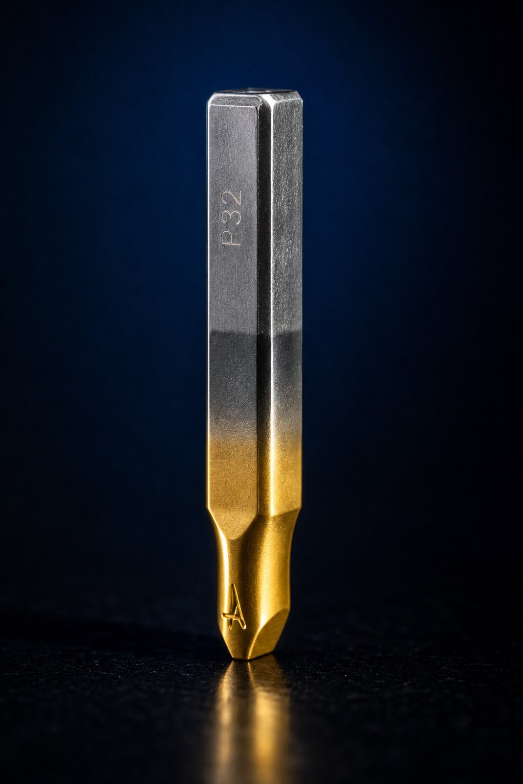
- Titanium nitride (TiN) - The general-purpose workhorse with its distinctive gold color. Hardness around 2,400 HV. Good abrasion resistance and low friction, suitable for a wide range of mild steel and copper alloy applications.
- Titanium carbonitride (TiCN) - A step up at roughly 3,200 HV. The added carbon provides better performance against abrasive materials and higher galling resistance. Often applied as a multilayer TiN/TiCN stack for improved adhesion.
- Aluminum chromium nitride (AlCrN) - Superior oxidation resistance at elevated temperatures. Ideal for tooling punches running at high stroke rates where frictional heat builds up, or for applications stamping stainless steel where surface temperatures climb during the cut.
- Titanium aluminum nitride (TiAlN) - Hardness around 3,200 HV with good thermal stability. Well suited for dry stamping or high-speed operations where lubrication delivery is inconsistent. Its ductility advantage over AlTiN can benefit forming-intensive punch tool for metal applications.
Coating thickness typically falls between 1 and 5 micrometers. The minimum recommended thickness for stamping applications is 4 to 5 micrometers to provide adequate protection. But thicker is not automatically better. PVD coatings carry high internal compressive stresses, and if the layer grows too thick, those stresses can exceed the bond strength and cause delamination. Excessive thickness also rounds cutting edges, degrading the sharpness that defines cut quality on an industrial hole punch or any precision piercing tool. Multilayer coating architectures help manage this trade-off by alternating harder and softer layers to arrest microcracks and distribute stress.
Nitriding and Other Diffusion Treatments
Where PVD adds a discrete film on top of the surface, nitriding changes the surface itself. In this process, nitrogen diffuses into the steel at around 950 degrees Fahrenheit, forming hard nitride compounds with alloying elements already present in the material. The result is a metallurgical bond with case depths ranging from 0.0006 to 0.0035 inches depending on the application, producing surface hardness exceeding 58 HRC.
Why does this matter for stamping? Nitriding adds no measurable dimensional buildup. For tight-tolerance tooling punches where even a few microns of coating thickness could affect fit in a press-fit retainer, nitriding delivers wear resistance without changing the punch diameter. It also treats all exposed surfaces uniformly, including interior features and recesses that PVD's line-of-sight process cannot reach.
The trade-off is that nitriding's hardness depth, while impressive, cannot match the extreme surface hardness of PVD films. Think of it this way: nitriding provides a deep, tough protective layer that resists fatigue and wear gradually, while PVD provides a thin, extremely hard shell that excels against abrasion and adhesion at the immediate contact surface. For an industrial hole puncher running high volumes in mild steel, nitriding alone may be sufficient. For abrasive or galling-prone materials, PVD coatings or a combination approach delivers better results.
Selecting Coatings Based on Failure Mode
The smartest approach to coating selection starts with identifying how the punch is actually failing. Different wear mechanisms respond to different coating properties:
- Adhesive wear (galling) - Material from the workpiece transfers and builds up on the punch face. Choose TiCN or AlCrN for their low coefficient of friction and high hardness that resists material pickup.
- Abrasive wear - The cutting edge gradually rounds over from contact with hard workpiece surfaces or abrasive inclusions. TiN or TiAlN provide the surface hardness needed to resist mechanical removal of material.
- Built-up edge on soft materials - Aluminum, copper, and soft steels tend to smear onto tooling surfaces. A polished TiN coating with its smooth, low-friction surface prevents nucleation sites where material pickup begins.
- High-temperature applications - Rapid stroke rates or thick, high-strength workpieces generate frictional heat that degrades conventional coatings. AlCrN maintains its properties at temperatures where TiN begins to oxidize.
One caution worth repeating: coatings address symptoms. If an industrial hole punch is galling because clearance is too tight or the press has alignment issues, no coating will solve that permanently. The coating buys time, but the root cause will eventually overwhelm even the best surface treatment. Fix the system first, then let coatings extend what good practice already delivers.
Coatings protect the punch surface, but they cannot compensate for the single most influential geometric variable in the die: the clearance gap between punch and die opening. That relationship determines whether the fracture mechanics work in your favor or against it.
Punch and Die Clearance by Workpiece Material
You can spec the best steel, apply a premium coating, and grind a flawless cutting edge, but none of it matters if the gap between your punch and die opening is wrong. Clearance is the single variable that controls whether fracture lines from the upper and lower cutting edges meet cleanly in the middle of the sheet or miss each other entirely. Get it right and you produce clean parts with predictable tool wear. Get it wrong and you are fighting burrs, chipping, slug pulling, and premature edge breakdown on every stroke.
How Clearance Affects the Shearing Mechanism
Clearance is defined as the gap per side between the punch's cutting edge and the corresponding edge of the die opening. When you hear "10% clearance," that means the gap on each side equals 10% of the workpiece thickness. This is not total gap. It is measured at each edge independently.
When clearance is correct, the shearing mechanism produces a predictable three-zone fracture on the cut edge:
- Rollover - A slight rounding at the punch-entry side where the material deforms plastically before the cut initiates.
- Burnish (shear zone) - The smooth, shiny band where the punch and die edges actively sheared the material. This is the cleanest portion of the cut face.
- Fracture (break zone) - The rougher, matte-finished area where cracks propagating from the punch edge and die edge met and the remaining material separated.
In a properly set punch and die press, the fracture lines initiated by the punch on the top surface and the die on the bottom surface propagate toward each other at complementary angles. They meet in the middle, producing a clean separation with minimal secondary damage. The ideal appearance, as documented in AHSS research, shows a uniform burnish zone with a smooth, uniform transition to the fracture zone and no voids or secondary shear marks.
When clearance is too tight, those fracture lines miss each other. The material between them undergoes a second shearing event, producing secondary shear marks, microcracks, and a rough, damaged edge. Tight clearance also dramatically increases the force required to strip the sheet from the punch, accelerates abrasive wear, and can generate slug pulling where the slug sticks to the punch face on retraction.
When clearance is too loose, the material bends excessively before fracture initiates. You get large rollover, oversized burrs, poor hole cylindricity, and a fracture zone that dominates the cut face. The part might be dimensionally out of spec, and downstream forming operations see reduced edge ductility because the deformed zone extends deeper into the material.
Material-Specific Clearance Guidelines
Different workpiece materials fracture in different ways. Softer, more ductile metals tolerate tighter clearances because they deform plastically rather than cracking prematurely. Harder, higher-strength metals need more room because their fracture initiates earlier and propagates more aggressively. The table below provides starting-point clearance values for a standard sheet metal punch and die set. These are per-side values expressed as a percentage of material thickness.
| Material | Recommended Clearance (% of thickness per side) | Notes |
|---|---|---|
| Mild steel | 5-8% | Standard baseline; lower end for thin gauges, higher for thicker stock |
| Stainless steel | 6-10% | Work-hardening rate demands more clearance to avoid excessive tool wear |
| Aluminum | 3-5% | Soft and ductile; tight clearance gives cleaner edge with less rollover |
| Copper / Brass | 3-6% | Similar to aluminum; galling risk on punch face is the primary concern |
| High-strength steel (HSLA, AHSS) | 8-12% | Higher strength requires increased clearance; some AHSS grades benefit from 14-16% |
These values are starting points, not absolutes. Actual clearance depends on several interacting factors: material thickness, desired edge quality, part tolerance requirements, and punch geometry. A metal punch and die running a 0.5 mm aluminum sheet will use a different clearance percentage than the same alloy at 3.0 mm thickness. Thicker materials within the same grade generally need clearance percentages toward the higher end of the range.
For advanced high-strength steels, the old rule of thumb that "10% works for everything" simply does not hold. Research on complex phase steels has shown that increasing clearance from 10% to 15% produced significant improvement in hole expansion performance, indicating a cleaner, more ductile edge. Going beyond the optimum, however, provides diminishing returns and can actually reduce edge quality. The sweet spot varies by grade, so testing with your specific material and punch and die set for hydraulic press or mechanical press is worth the investment.
Clearance and Its Relationship to Punch Life
Clearance does not just affect part quality. It directly determines how fast your metal punches and dies wear out.
Insufficient clearance forces the punch to work harder on every stroke. The material resists separation longer, stripping forces climb, and the cutting edge endures more abrasive contact per cycle. Research confirms that small cutting clearances require greater punching forces and cause greater punch wear from abrasion. In extreme cases, the lateral compression on the punch body can cause fatigue cracking or chipping at the cutting edge, especially on high-strength materials where the narrow gap creates bending stresses at the punch periphery.
Excess clearance reduces mechanical stress on the tooling. The punch enters and exits with less friction, and stripping force drops. That sounds like a win for tool life, and it is, but it comes at the cost of part quality. Larger burrs, more rollover, and reduced edge ductility mean you might save on resharpening intervals but lose on scrap rates and secondary deburring operations. The net cost often ends up higher.
Here is what many shops overlook: clearance is not just a number on a print. It is a dynamic condition that changes under load. Even a perfectly ground sheet metal punch and die set loses its intended clearance if the press and die system has worn gibs, deflecting bolsters, or misaligned guide pins. The higher loads required to shear stronger materials create additional deflection of dies and processing equipment, potentially altering clearances measured under a static condition once the system is under working load. A press that was aligned for mild steel at 40 tons may shift enough at 80 tons on AHSS to invalidate your clearance setup entirely.
This means maintaining correct clearance is an ongoing discipline, not a one-time setup task. Periodic press alignment checks, wear measurement on guide components, and monitoring of cut-edge appearance under production conditions all feed back into whether your clearance is still where you set it. When edge quality starts to drift, the root cause is often not the punch wearing out. It is the press and die alignment shifting underneath it, silently changing the clearance that everything else depends on.
Clearance degradation and alignment drift often show up disguised as punch failure. Chipping that looks like a material problem, galling that looks like a coating problem, or breakage that looks like a design flaw can all trace back to a clearance issue that developed gradually over thousands of hits. Distinguishing the real root cause from the symptom is what separates reactive die maintenance from a systematic approach to punch longevity.
Punch Failure Modes and Root Cause Analysis
A punch that stops working rarely gives you a single, obvious reason why. The chipped edge you find during a die pull could be caused by the wrong steel, tight clearance, a misaligned press, or all three acting together over thousands of cycles. Jumping to the most visible symptom and swapping the tool without investigating further guarantees the replacement will fail the same way. What tooling engineers need is a structured diagnostic approach that connects what they see on the punch to what actually caused it.
Common Punch Failure Modes
Every failure you encounter on a metal punch machine falls into one of these categories. Recognizing which mode is present narrows your root cause investigation immediately:
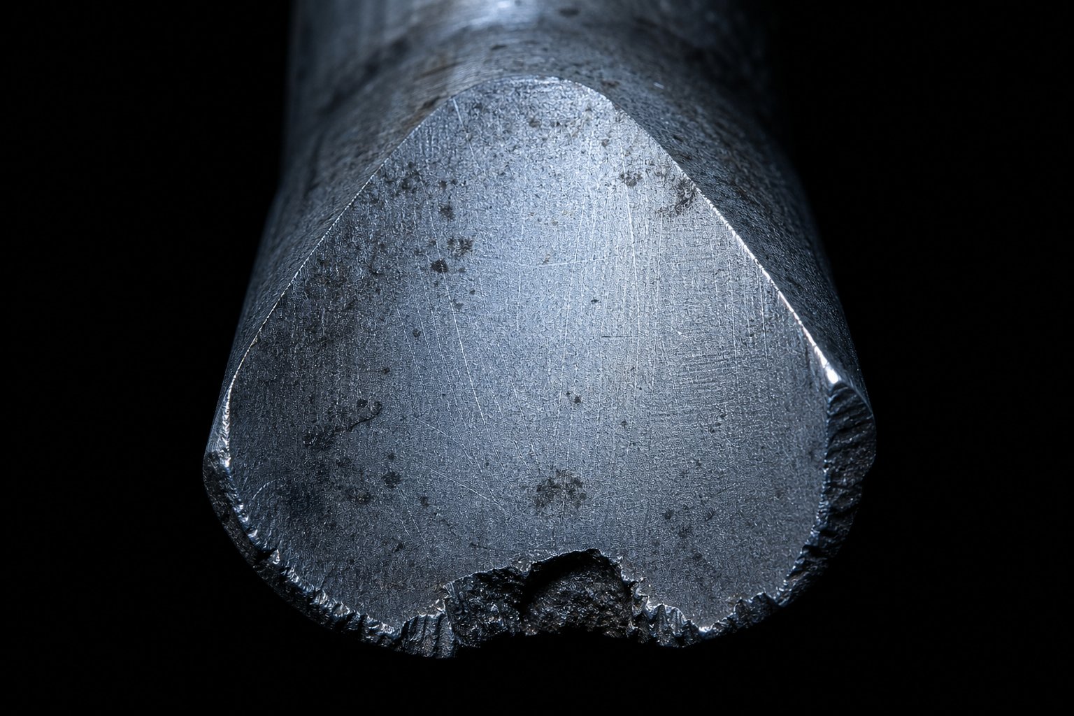
- Chipping - Small fractures along the cutting edge, often crescent-shaped. This is the most common early-stage failure on punch press dies running high-strength materials. It indicates the punch lacks sufficient toughness for the load, or that misalignment is concentrating stress on one section of the perimeter. Misalignment between punch and die creates asymmetric loading that drives chipping on the overloaded side.
- Galling - Workpiece material transfers and bonds to the punch surface through adhesive wear. You will see buildup, scoring, or rough patches on the punch face and land. Galling is especially aggressive when stamping stainless steel and aluminum, where the workpiece's oxide layer breaks during shearing and exposes fresh, reactive metal that welds to the tool surface under pressure.
- Breakage - Catastrophic fracture where the punch snaps, usually at a cross-sectional transition or at a point of excessive unsupported length. Compressive failure can shatter the entire working end of the punch when it encounters extremely hard or thick material beyond its capacity, or when the punch and die are completely misaligned.
- Abrasive wear - Gradual, uniform rounding of the cutting edge caused by hard particles in the workpiece or abrasive inclusions in the sheet surface. Unlike chipping, abrasive wear progresses predictably and can be tracked through periodic edge inspection. It is the dominant failure mode on a metal punching machine running HSLA or coated steels at moderate speeds.
- Mushrooming - The punch head deforms and spreads outward from repeated impact against the backing plate or retainer. This happens when the punch is not fully seated, when the backing plate is too soft, or when the coupling nut loosens and allows uneven stem contact. A mushroomed head can jam in the retainer and make punch removal difficult or dangerous.
- Slug pulling - The slug adheres to the punch face during retraction and rides back up with the tool. On the next stroke, the slug enters between the punch and strip, causing a double-thickness hit that can damage the die, dent the next part, or crack the punch itself. Insufficient land length, weak vacuum-break features, or magnetized tooling are the usual culprits.
Root Cause Diagnosis Framework
When you pull a damaged punch from the die, the visible failure tells you what happened. The table below maps that observation back to why it happened and what corrective action actually fixes the problem rather than just replacing the symptom. This framework applies whether you are running a single-station punch press or a high-speed progressive die in a punching press line.
| Failure Mode | Primary Causes | Corrective Actions |
|---|---|---|
| Chipping | Insufficient toughness for workpiece strength; tight clearance causing secondary shear; punch-to-die misalignment; improper heat treatment leaving brittle retained austenite | Switch to tougher steel grade (A2 or S7); increase clearance to recommended range; verify alignment with indicator; re-temper or replace with properly heat-treated punch |
| Galling | Lack of lubrication at punch-workpiece interface; punch surface too rough; reactive workpiece material (stainless, aluminum); insufficient clearance generating excess heat | Apply TiCN or AlCrN coating; polish punch land area; improve lubrication delivery; increase clearance to reduce frictional heat buildup |
| Breakage | Excessive unsupported punch length (length-to-diameter ratio too high); overloading from wrong material or double-hit; complete misalignment; hardness too high with no toughness | Reduce unsupported length with guided stripper; verify tonnage capacity; realign punch and die concentrically; select shock-resistant steel for heavy applications |
| Abrasive wear | Workpiece harder or more abrasive than punch surface; no coating on punch running abrasive stock; excessive hits between sharpening intervals | Upgrade to PM steel grade or add PVD coating; reduce sharpening intervals; verify workpiece hardness matches original tool specification |
| Mushrooming | Punch not seated fully in retainer; backing plate softer than punch head; loose coupling or fastener allowing impact cycling; head hardness too low | Verify full seating depth; use hardened backing plate matching or exceeding punch head hardness; tighten and inspect coupling nut regularly |
| Slug pulling | Land length too short for material thickness; no vacuum-break feature (spring pin, air blast); magnetized punch after grinding; tight clearance creating suction effect | Increase land to 1-3x material thickness; add ejector pin or air blast to punch face; demagnetize after every sharpening; open clearance slightly if within tolerance |
Notice that several failure modes share overlapping root causes. Tight clearance appears in chipping, galling, and slug pulling. Misalignment drives chipping, breakage, and uneven wear. This means a single underlying issue in the press or die setup often produces multiple symptoms simultaneously. If you see chipping on one punch and galling on an adjacent one in the same die, do not treat them as separate problems. Look for the shared root cause, which is frequently press alignment or clearance drift affecting the entire tool.
How Punch Design Prevents Quality Defects
Punch condition is not just a maintenance concern. It is a quality control variable that directly shows up on finished parts. Every defect on the punch face has a corresponding defect on the stamped component:
- Worn cutting edges produce increased burr height on every hole or contour the punch creates. As The Fabricator notes, when a visibly larger rollover appears on the punched edge, it is time to sharpen. Burrs above acceptable limits create assembly interference, safety hazards during part handling, and failures in downstream welding or plating operations.
- Chipped punches produce inconsistent hole sizes. The missing edge material creates a local area where shearing does not initiate properly, leading to irregular hole geometry and uneven edge profiles. Parts may pass initial inspection but cause issues in assembly when fastener fit becomes unpredictable.
- Galled punches produce holes with rough interior surfaces and material smearing. The built-up material on the punch face effectively changes the punch diameter and geometry with each stroke, creating progressive quality drift that is hard to catch without regular inspection.
- Slug pulling creates dents on the sheet surface when the carried slug gets pressed into the next part. It can also damage the die face and cause cascading failures across multiple stations in a progressive tool.
This connection between punch condition and part quality is why monitoring should happen at the machine punch station, not just at final inspection. By the time a quality defect reaches the end of the line, hundreds or thousands of nonconforming parts may already be in the bin. Punch presses running high-volume production benefit most from in-process monitoring approaches: tracking burr height trends, inspecting slugs for double-shear marks, and measuring hole diameter samples at regular intervals. When those indicators shift, the punch is telling you something has changed, whether it is wear, alignment, or clearance drift.
Catching failure modes early rather than waiting for catastrophic breakdown also changes the economics. A punch resharpened at the first sign of edge wear loses a few thousandths of material per grind and returns to service quickly. A punch run to destruction loses its entire working length and may damage adjacent die components on the way out. The next section covers exactly when and how to resharpen, inspect, and replace punches to keep failure modes from ever reaching the catastrophic stage.
Maintenance and Resharpening Best Practices for Punches and Dies
A punch does not go from sharp to broken in one stroke. It degrades gradually, and the window between "still cutting clean" and "producing scrap" is where maintenance pays for itself. The problem is that most shops resharpen too late. They wait until burrs are obvious, parts are failing inspection, or the press sounds different. By that point, the edge has worn well past the easy-recovery stage, and each regrind removes far more material than it should.
When and How to Resharpen Punches
The trigger for resharpening is not catastrophic failure. It is the first measurable increase in burr height on your stamped parts. Mate recommends sharpening when cutting edges wear to a 0.01-inch (0.25 mm) radius. At that point, a light touch-up restores the edge with minimal material loss. Frequent light grinds consistently outperform infrequent heavy grinds because they keep the cutting geometry closer to its designed profile and reduce cumulative material removal over the tool's life.
The resharpening procedure itself is straightforward but demands discipline:
- Clamp the punch squarely in a V-block on the magnetic chuck of a surface grinder.
- Remove only 0.001 to 0.002 inches (0.03 to 0.05 mm) per pass, repeating until sharp. Total removal per session is typically 0.005 to 0.010 inches.
- Use a vitrified bond aluminum oxide wheel, hardness range D to J, grain size 46 to 60.
- Apply coolant generously and as close to the contact point as practical. Overheating draws back hardness and can produce surface cracks that are invisible but structurally devastating. Dark discoloration after grinding indicates damage that extends beyond the surface, and the tool should be replaced rather than reused.
- After grinding, lightly stone the cutting edges with an oil stone to leave a 0.001 to 0.002-inch radius. This tiny radius distributes stress at the edge and reduces the flaking that causes rapid re-dulling on freshly ground sheet metal punches.
- Demagnetize the punch and apply a light oil coat to prevent corrosion before returning it to service or storage.
Total resharpening allowance depends on original punch length and land consumption. Once accumulated grinding removes material equal to or exceeding the designed land length, the punch can no longer retain slugs properly and must be retired. For a typical sheet metal punch tool with a land of 1 to 3 times material thickness, that means tracking every grind session and recording cumulative removal.
Inspection and Replacement Criteria
Resharpening keeps metal punching tools in service, but it does not make them immortal. A well-maintained punch can be reground 15 to 20 times before replacement, but each cycle must be verified against clear acceptance criteria. Here is what to check after every regrind, and at regular intervals during production runs:
- Edge condition - Inspect under magnification (10x minimum). Look for microchips, uneven wear patterns, or grinding burn marks that indicate subsurface damage.
- Diameter measurement - Use a go/no-go gauge or micrometer to confirm the punch still falls within tolerance. Cumulative regrinding can subtly reduce effective diameter if the grinding setup is not perfectly square.
- Length verification - Measure overall length and compare to the original spec minus documented grind history. Length determines shut height and affects timing in progressive dies where punch pins and other components interact at precise positions.
- Surface finish - The land and face should be smooth and free of scoring or adhesion marks. Rough surfaces promote galling and slug pulling.
- Head condition - Check for mushrooming, cracks, or deformation from repeated impact against the backing plate.
Replace the punch when any of these conditions apply: accumulated grinding has consumed the full land length, chipping extends beyond the immediate edge zone into the punch body, diameter falls outside the tolerance band for the hole specification, or head damage prevents proper seating in the retainer. Do not attempt to salvage a borderline tool for "just a few more hits." A failing punch that breaks in the die costs far more in downtime and collateral damage than a planned replacement.
Storage and Handling Practices
The time punches spend outside the die matters more than most shops realize. A dropped punch is almost certainly damaged at the cutting edge, even if the ding is not visible to the naked eye. Careless storage where tools contact each other creates edge nicks that initiate chipping under load.
Store punches in individual protective tubes with foam, cotton, or wax to keep precision-ground edges intact. Never store cutting ends down where the tool's weight rests on its sharpest feature. Label each tube or slot with the punch identification, current diameter, and regrind count so anyone pulling a tool from inventory knows exactly what they are working with.
For shops running a full die punch tool set with multiple sizes and geometries, organized storage is not housekeeping. It is quality assurance. A mislabeled punch installed in the wrong station creates clearance problems, dimensional errors, and potential die damage on the first hit. Pair your storage system with a simple log that tracks each tool from new through every regrind to retirement.
Maintenance keeps individual punches performing. But the broader question, selecting the right combination of punch type, material, geometry, and coating for a specific application, is what determines whether your maintenance intervals are measured in tens of thousands of hits or hundreds of thousands.
Selecting the Right Punch for Your Metal Stamping Die Application
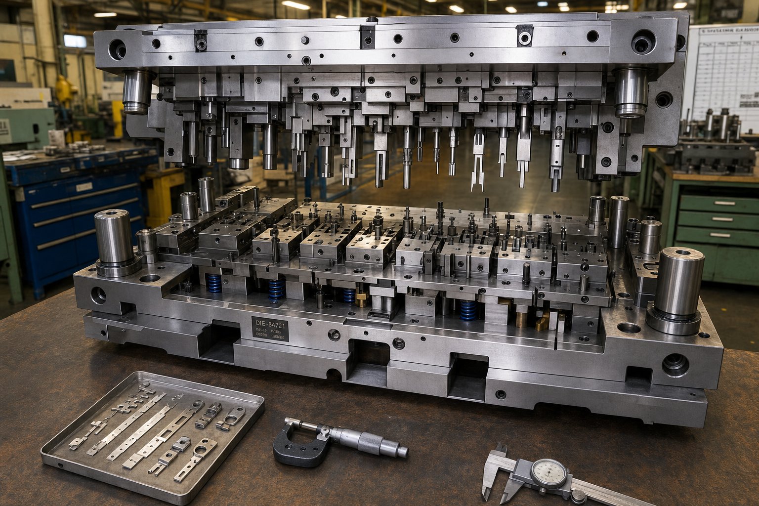
Every section of this article points to the same conclusion: punch performance is not controlled by a single variable. Steel grade matters, but not in isolation from geometry. Coatings extend life, but not if clearance is wrong. Maintenance preserves quality, but not if the original design was a poor match for the workpiece. The real fix for premature wear is a systematic selection process that accounts for all of these factors together, in sequence, before the first hit lands on the die press.
Decision Variables for Punch Selection
When specifying a new punch or troubleshooting an underperforming one, work through these variables in order. Each step narrows the field and builds on the previous decision:
- Identify the operation type. Is the punch cutting (piercing, blanking, notching) or forming (bending, drawing, coining)? Cutting operations demand sharp edges and wear-resistant steels. Forming operations prioritize toughness and surface finish.
- Characterize the workpiece material and thickness. Soft aluminum at 0.5 mm and 1400 MPa martensitic steel at 1.5 mm impose completely different demands on the metal stamping tool. Material strength and abrasiveness determine the minimum steel grade and whether a coating is mandatory or optional.
- Determine required clearance. Use the material-specific guidelines from the previous sections as a starting point. Factor in part tolerance, desired edge quality, and press rigidity. Tighter tolerances on hole size push toward tighter clearances but increase tool stress.
- Select the punch material grade. Match toughness requirements first, then add wear resistance. D2 for general work, S7 for shock, PM grades for abrasive or high-strength sheets. Let the workpiece dictate the steel, not budget alone.
- Choose geometry and point style based on force and quality needs. Flat-face for symmetry-critical holes. Single-shear or roof-top for force-limited presses or high-strength materials. Set land length and back taper based on material thickness and slug-retention needs.
- Evaluate coating based on expected failure mode. If the primary risk is galling, choose TiCN or AlCrN. If abrasive wear dominates, TiN or TiAlN. If no single failure mode is dominant, a general-purpose TiN at 4-5 micrometers is a sound baseline.
This sequence works whether you are specifying a standard catalog punch for a simple press machine die or engineering a custom die punch for a complex progressive tool. The logic stays the same. What changes is the complexity of each answer.
Working with Custom Stamping Die Specialists
Standard catalog punches handle a large share of production work. But when geometries get complex, tolerances tighten below standard ranges, or workpiece materials push into advanced high-strength territory, off-the-shelf tools hit their limits. That is where custom metal stamping die specialists become essential.
What separates a capable tooling partner from a parts supplier? Look for these capabilities:
- System-level expertise - The ability to design not just the punch, but the entire die structure: clearances, material flow, stripping forces, and burr control as an integrated system.
- Full lifecycle support - Guidance from initial design through production optimization and maintenance recommendations, not just delivery of a finished component.
- Material and process knowledge - Experience with the specific workpiece materials and production volumes in your operation, including custom die cut punch solutions for non-standard profiles.
For engineers who have worked through the technical content in this article and need a partner for implementation, YICHEN offers custom stamping die solutions covering punch design, die structure, clearance optimization, and material flow. Their engineering-first approach addresses the full system rather than isolated components, which is exactly the mindset this article has been building toward.
The key distinction between punch and die manufacturers who deliver results and those who simply fill orders is whether they treat the punch as a standalone part or as one element in a system that must perform together. The best partners challenge your assumptions, validate your clearance choices, and recommend steel and coating combinations based on their field data from similar applications.
Putting It All Together
If there is one principle that connects every section of this article, it is this:
Punch performance is a system outcome. Material, geometry, clearance, coating, press condition, and maintenance practices interact continuously. Optimizing one variable while ignoring the others produces diminishing returns at best and accelerated failure at worst. The real fix for premature wear is never a single change. It is getting the entire system right.
Whether you are running a simple single-station die press or a 30-station progressive tool, the physics do not change. The punch enters the material, fracture initiates, and everything you specified upstream determines whether that fracture produces a clean part or a quality problem. Work through the variables systematically, partner with specialists when the application demands it, and treat punch maintenance as a quality function rather than a breakdown response. That is how stamping die punches stop wearing too fast and start delivering the tool life your production schedule actually requires.
Frequently Asked Questions About Stamping Die Punches
1. What causes stamping die punches to wear out prematurely?
Premature punch wear typically stems from multiple interacting factors rather than a single cause. The most common contributors include incorrect punch-to-die clearance (especially too tight), mismatched tool steel for the workpiece material, improper heat treatment leaving brittle retained austenite, press misalignment that creates uneven loading, and waiting too long between resharpening cycles. Addressing punch wear requires a system-level approach that evaluates material selection, geometry, clearance, coating, and press condition together. Custom stamping die specialists like YICHEN can help engineers optimize these variables as an integrated system rather than treating each one in isolation.
2. How do I choose the right clearance for my punch and die set?
Clearance selection depends primarily on workpiece material and thickness. Start with these per-side guidelines: mild steel at 5-8% of material thickness, stainless steel at 6-10%, aluminum at 3-5%, copper and brass at 3-6%, and high-strength steels at 8-12%. These are starting points that must be adjusted based on part tolerance requirements, desired edge quality, and press rigidity. Remember that clearance is dynamic under load. Press deflection, worn gibs, and misaligned guide pins can all change your effective clearance from what was measured statically, particularly when stamping AHSS grades at higher tonnages.
3. What is the best tool steel for stamping die punches?
There is no single best steel because the right choice depends on your workpiece material and operation type. D2 is the general-purpose workhorse for mild steel stamping at 54-61 HRC. A2 offers better toughness for long punches and moderate shock loads. S7 handles heavy blanking where impact resistance matters most. M2 high-speed steel suits high-speed operations generating frictional heat. CPM-10V and other powder metallurgy grades deliver extreme wear resistance for abrasive or advanced high-strength steels. The key principle is to satisfy toughness requirements first, then add wear resistance through coatings or surface treatments.
4. How often should stamping die punches be resharpened?
Resharpen when cutting edges wear to a 0.01-inch (0.25 mm) radius, which typically shows as the first measurable increase in burr height on stamped parts. Do not wait for visible damage or catastrophic failure. During resharpening, remove only 0.001 to 0.002 inches per grinding pass with generous coolant to prevent heat damage. A well-maintained punch can be reground 15 to 20 times before replacement. Track cumulative material removal and retire the punch once total grinding exceeds the designed land length, as it can no longer retain slugs properly beyond that point.
5. Do PVD coatings actually extend punch life in stamping dies?
Yes, but only when the underlying tooling fundamentals are correct. PVD coatings like TiN, TiCN, AlCrN, and TiAlN reduce friction, resist material pickup, and slow abrasive wear. Documented cases show improvements from 10,000 to 250,000 parts with optimized coatings. However, coatings multiply good decisions rather than compensate for bad ones. If clearance is wrong, alignment is off, or the base steel is inappropriate, coatings provide only temporary relief. Select coatings based on the dominant failure mode: TiCN or AlCrN for galling, TiN or TiAlN for abrasive wear, and polished TiN for soft-material buildup.


