


What Transfer Die Stamping Is and Why Engineers Choose It
When a part is too large, too deep, or too geometrically complex to stay attached to a metal strip throughout forming, you need a different approach. That approach is transfer die stamping.
Defining Transfer Die Stamping
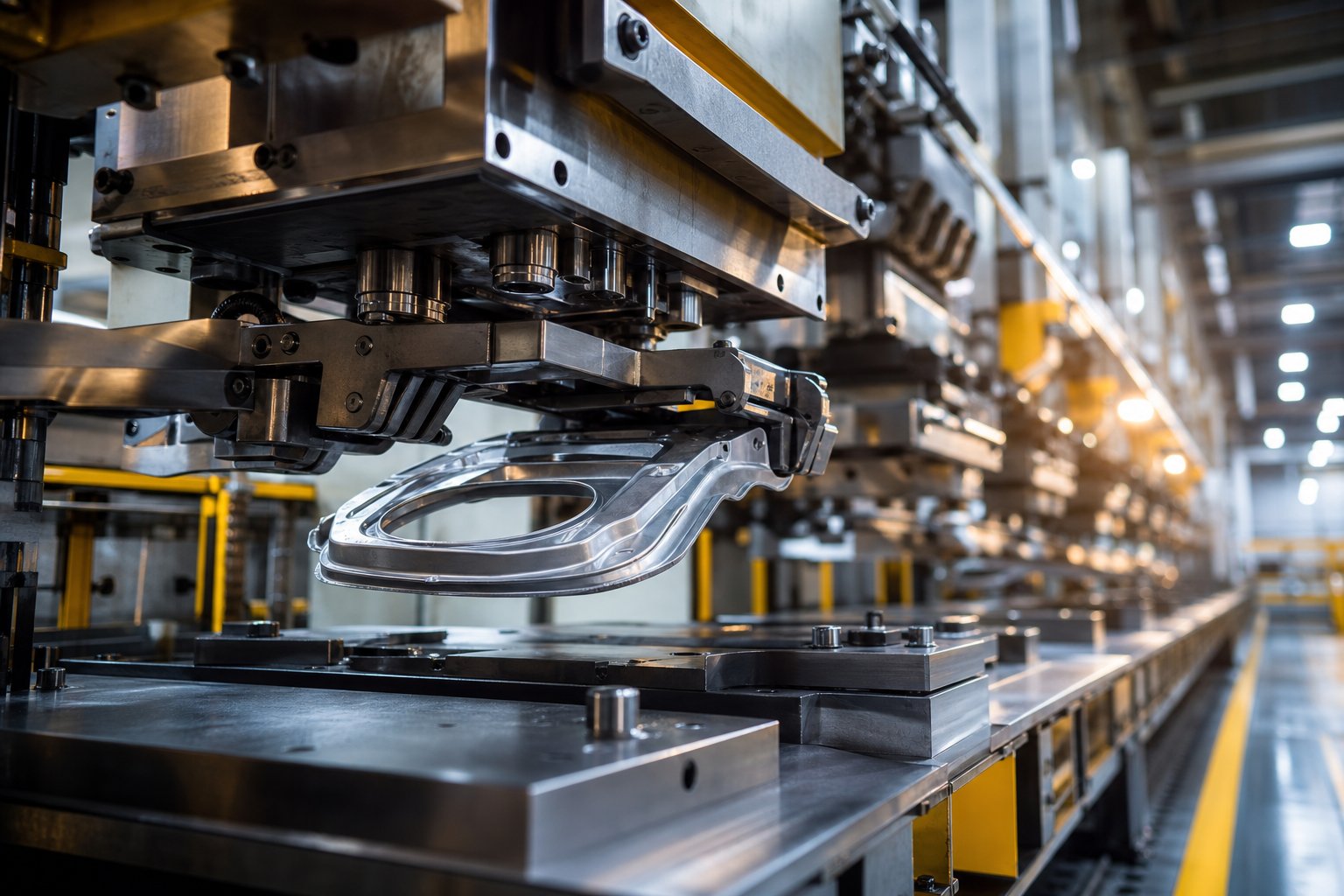
Transfer die stamping is a metal forming process in which individual blanks are separated from a coil or sheet, then mechanically moved between independent die stations by a transfer system that lifts, advances, and places each part for sequential operations such as drawing, piercing, bending, and trimming.
The critical distinction here is separation. Unlike progressive die stamping, where the workpiece remains connected to a continuous strip from start to finish, transfer stamping frees the blank early. A mechanical or servo-driven transfer mechanism then carries each piece through multiple stations inside a single press. Each station has its own dedicated die performing a specific operation, and the part is progressively shaped as it moves through the line.
Why This Process Exists as a Separate Category
Imagine you need to deep-draw a structural automotive bracket or form a large appliance housing with multi-axis geometry. Keeping that part tethered to a strip creates material flow problems, limits draw depth, and restricts the forming angles available to you. Transfer dies solve this by handling free-standing blanks that can be rotated, repositioned, and formed from multiple directions.
The types of parts that benefit most from this process share a few common traits:
- Larger geometries that exceed practical strip widths
- Deep draws requiring multiple redraw stages
- Complex shapes involving threading, ribs, knurls, or multi-axis bends
- Parts needing operations on both sides of the workpiece
Transfer dies fill a gap that neither single-hit tooling nor progressive stamping can address efficiently. They combine the multi-station productivity of die stamping with the geometric freedom that only a free blank provides.
This article is built as a process-engineering resource. You will find station-by-station mechanics, transfer system selection criteria, DFM rules, cost analysis frameworks, and honest guidance on when this method pays off and when it does not. The goal is to give you the technical grounding to make tooling decisions with confidence, starting with how the process actually operates at each stage.
How Transfer Die Stamping Works Station by Station
A free-standing blank does not move itself. Every transfer die stamping line depends on precise coordination between material feeding, forming operations, and the mechanical system that shuttles parts from one station to the next. Here is how each stage works in practice.
From Coil to Blank Separation
Most lines begin with a coil handling system that unwinds sheet metal and feeds it into a blanking station. The stamping feed method, whether coil-fed or pre-cut blanks loaded from a destacker, determines how the line starts. Coil feeding works well for square or rectangular blanks, while pre-cut blanks offer better material utilization for irregular shapes. In a coil/transfer hybrid setup, a progressive blanking die separates the material, and the transfer system picks up the resulting blank for all subsequent operations.
Blank quality matters here. Burr direction, flatness, and dimensional consistency all affect how reliably the transfer fingers grip and position the workpiece at the first forming station.
Station Operations in Sequence
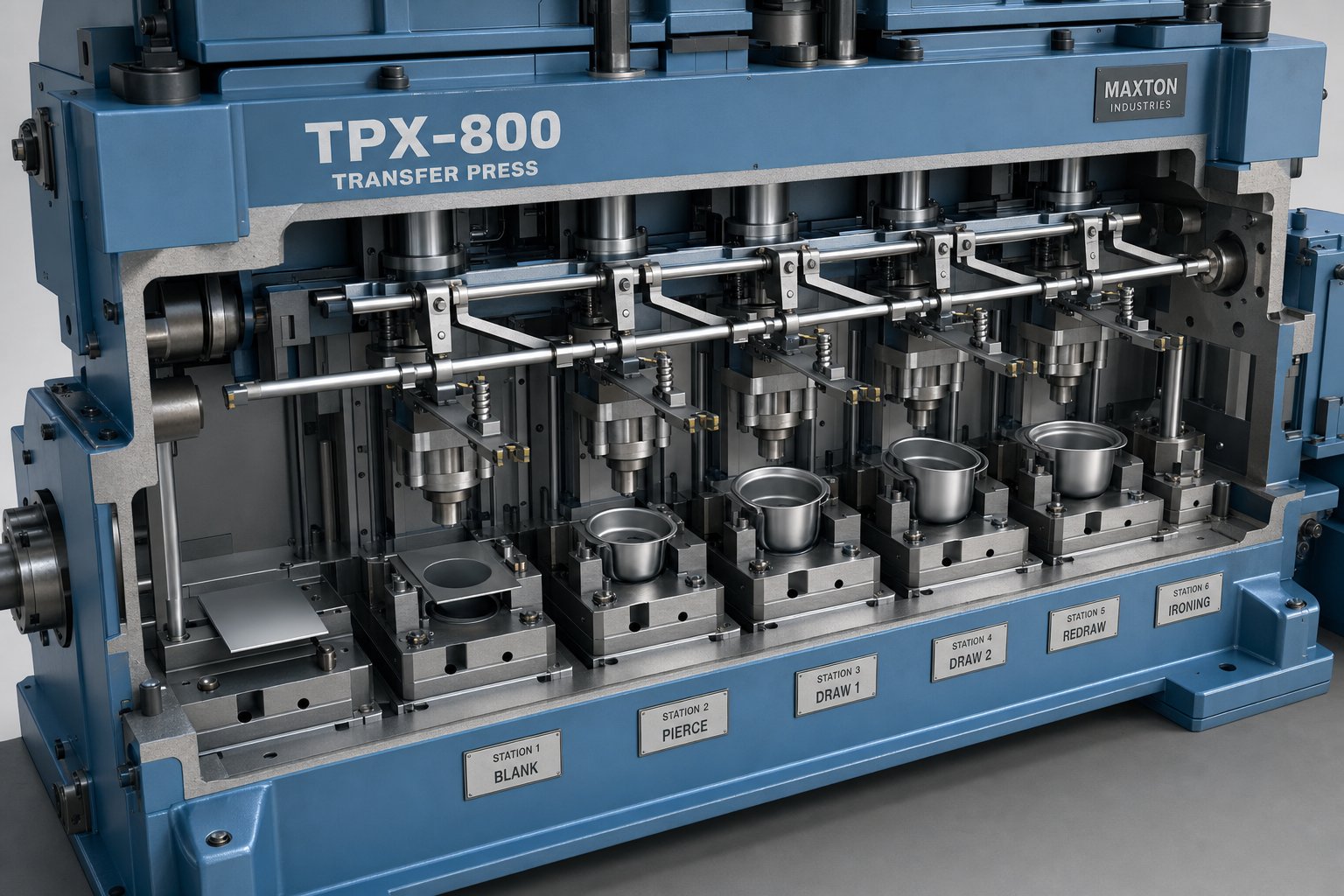
Once separated, the blank travels through a series of independent die stations, each performing a specific forming or cutting operation. A typical transfer press stamping sequence looks like this:
- Blanking - flat sheet is cut to the required profile
- First draw - initial cup or shell shape is formed
- Redraw - the shell is deepened or reshaped in one or more stages
- Piercing - holes, slots, or features are punched into the formed geometry
- Bending or flanging - edges are folded to final angles
- Coining or embossing - local areas receive precise thickness or surface detail
- Trimming - excess material and carrier features are removed to produce the finished part
Not every part requires all these stations. Some skip the redraw; others add idle stations to accommodate scrap removal or allow the pitch length to stay short. The number of stations multiplied by the pitch length (typically driven by blank size) must fit within the press bed, so station count is always a physical constraint, not just a process preference.
Press and Transfer Timing Coordination
The transfer mechanism lifts, advances, and places each part between stations in the window of time when the press ram is open. This timing relationship is the heartbeat of the entire line. The transfer must complete its full motion cycle, including finger return, before the ram descends for the next stroke.
In a mechanical transfer press, cam-driven motions are fixed to the press crank angle, meaning every lift, clamp, and advance happens at the same point in each revolution. Servo-driven systems offer programmable motion profiles that can adjust start times, accelerations, and dwell points independently. This flexibility allows higher strokes per minute because motion overlaps, such as beginning the advance before the lift is fully complete, can be fine-tuned without mechanical modification.
Press specifications directly constrain what a transfer die can accomplish. Tonnage determines the maximum forming force available across all stations simultaneously. Bed size limits the number and spacing of stations. Stroke length must accommodate both the depth of draw and enough clearance for the stamping feed fingers to enter and exit without interference. A mismatch between any of these parameters and the part requirements means the die either will not fit, will not form correctly, or will not run at a profitable speed.
These mechanical relationships between press stroke, transfer motion, and station layout explain why press stamping engineers invest heavily in upfront evaluation. But the transfer mechanism itself comes in several configurations, each suited to different part geometries and production demands.
Transfer System Types and How to Select the Right One
The transfer mechanism is what separates a multi-station press from a row of independent tools. It dictates how fast you can run, what part geometries you can handle, and how much time changeovers consume. Choosing the wrong system type for your application means leaving strokes per minute on the table or, worse, fighting instability every time the line speeds up.
Tri-Axis vs Two-Axis Transfer Mechanisms
Two-axis systems operate in a single plane, typically lift and advance (X-Z motion). They pick the part up off the die surface, carry it forward to the next station, and set it down. Positioning during finger retraction relies on spring pins to keep the workpiece from shifting before the die closes. These systems work well for parts with consistent profiles that do not require reorientation between stations.
Tri-axis systems add a clamp axis, producing lift-clamp-advance motion in the X-Y-Z planes. This three-axis movement allows the transfer tooling to grip the workpiece securely, lift it clear of lower-die components, advance it to the next station, and place it within tight perimeter-gauge boundaries. As Metal Forming Magazine notes, a combination of part geometry, nesting blocks, and locator pins maintains orientation during finger retraction in these systems.
Three-axis configurations are commonly plate-mounted or press-mounted, with transfer press tooling components designed to provide clearance for the fingers' return path while avoiding interference with lower-die steels, cams, and guiding components. Die-mounted variants can achieve faster stroke rates due to shorter travel distances, though they add design complexity.
Servo-Driven Systems and Their Advantages Over Mechanical Transfers
Traditional cam-driven transfer presses tie every motion to the press crank angle. The lift, advance, and clamp timings are fixed, meaning they cannot adapt to different part weights or geometries without mechanical adjustment. This rigidity works fine for dedicated lines running one part family for years.
Servo-driven systems change the equation. Motion profiles become programmable, so an operator can adjust travel distances, acceleration curves, and the timing of when each axis begins and ends its movement. The practical advantages are significant:
- Faster changeover - new motion profiles load digitally rather than requiring cam swaps
- Higher SPM potential - motion overlap (starting advance before lift completes) can be fine-tuned without hardware changes
- Asymmetric part handling - different acceleration profiles on each side compensate for uneven weight distribution
- Reduced vibration - rounded motion transitions and optimized G-forces improve blank stability at speed
Larger, heavier workpieces demand stronger transfer arms and fingers, which increases system inertia and often requires slower operating speeds. Transfer-motion simulation helps determine a profile that balances acceptable inertia levels, accurate positioning, and long transfer-system life. Thin materials present the opposite challenge: less stiffness makes them vulnerable to vibration during high-acceleration moves.
| Attribute | Two-Axis (Mechanical) | Tri-Axis (Mechanical) | Servo-Driven (2 or 3 Axis) |
|---|---|---|---|
| Motion Axes | Lift + Advance | Lift + Clamp + Advance | Programmable (2 or 3 axes) |
| Speed Range (SPM) | Moderate (fixed curve) | Moderate (fixed curve) | High (optimizable overlap) |
| Part Weight Capacity | Light to medium | Medium to heavy | Full range (profile-dependent) |
| Changeover Time | Long (mechanical swap) | Long (mechanical swap) | Short (digital profile load) |
| Best-Fit Applications | Simple geometries, consistent profiles | Deep draws, large panels, multi-plane parts | Mixed production, asymmetric parts, high-SPM targets |
Selection ultimately comes down to matching the system to your production reality. A dedicated high-volume line running one deep-drawn housing for ten years may justify a robust tri-axis mechanical system. A facility stamping multiple part numbers on shared transfer presses benefits from servo flexibility and faster changeover. Part geometry, weight, speed targets, and station spacing each narrow the field, but the decision also hinges on how your tooling mix will evolve over the life of the equipment.
Of course, the transfer system is only half the equation. The other half is whether a transfer die is the right tooling strategy at all, or whether a progressive die could handle the job at lower cost and shorter lead time.
Transfer Die Stamping vs Progressive Die Stamping
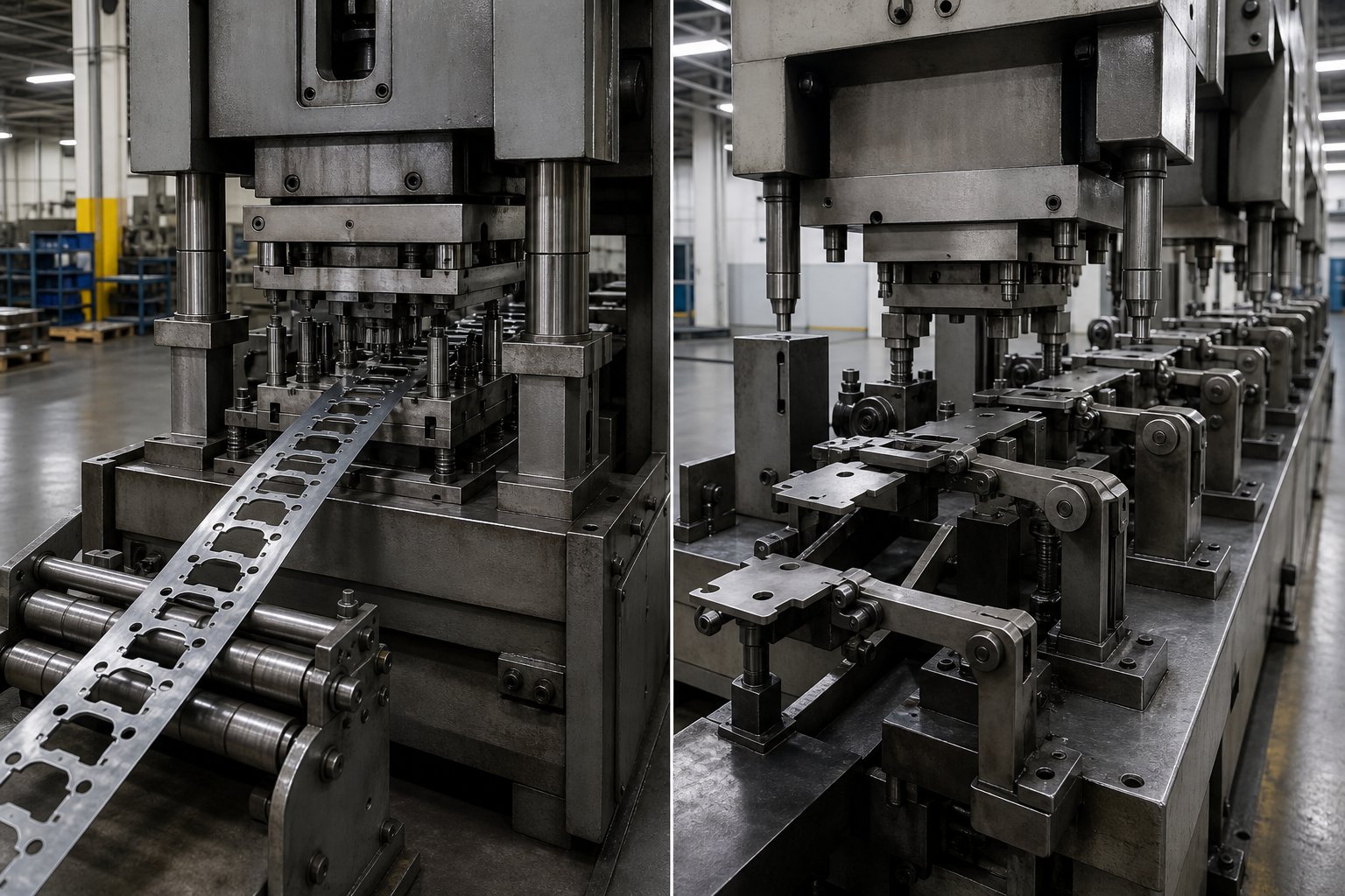
So what is a progressive die, and when does a part outgrow one? A progressive stamping die keeps the workpiece attached to a continuous metal strip as it advances through each station. That strip connection is both the process's greatest efficiency advantage and its fundamental geometric constraint. Progressive dies excel at speed and material utilization for parts that can be fully formed while still tethered. Transfer dies take over where that tether becomes a limitation.
The real question is not which method is better. It is which method matches the specific demands of your part, your volume, and your budget.
Key Selection Criteria for Each Process
Several measurable factors determine whether progressive die stamping or transfer die stamping is the right fit:
- Part geometry complexity - Progressive metal stamping handles flat or shallow-formed geometries efficiently, but parts requiring deep cups, multi-axis bends, or operations on both sides of the workpiece need the freedom a transfer die provides.
- Part size - Strip width and press bed dimensions limit progressive dies. Once a part exceeds roughly 300-450 mm in its largest dimension, maintaining strip integrity becomes impractical. Transfer tooling handles large shells, frames, and structural panels without this constraint.
- Draw depth - Progressive stamping can manage shallow draws, typically under 1:1 depth-to-diameter ratios. Deeper draws demand multiple redraw stages with the blank in a free state, which only transfer systems support.
- Material thickness - Very thin stock (below 0.5 mm) feeds and pilots well in progressive dies. Thicker materials, especially above 3 mm, generate higher forming forces and more significant springback, often favoring transfer setups where station-to-station repositioning improves control.
- Tolerance requirements - Both methods achieve tight tolerances, but transfer dies allow individual station adjustments without affecting upstream operations. Progressive dies require the entire strip to remain precisely aligned, making localized corrections more difficult.
| Criterion | Progressive Die Stamping | Transfer Die Stamping |
|---|---|---|
| Part Size | Small to medium (limited by strip width) | Medium to large (limited by press bed) |
| Draw Depth | Shallow (typically less than 1:1 ratio) | Deep (1:1 or greater, multiple redraws) |
| Number of Stations | Often 8-20+ in a single die block | Typically 4-12 independent stations |
| Material Utilization | Higher (continuous strip, less scrap) | Moderate (blank nesting dependent) |
| Tooling Cost | Higher upfront (single complex die block) | Lower per station but cumulative with station count |
| Ideal Volume Range | High volume (500K+ annually) | Medium to high (50K-500K+ annually) |
The Gray Zone Where Both Methods Compete
Not every part falls neatly into one category. A medium-sized bracket with moderate draw depth and a few pierced features could technically run in either a progressive or transfer die. You will encounter this gray zone regularly, and the decision often comes down to secondary factors rather than hard limits.
Consider a drawn housing roughly 150 mm in diameter with a 1:1 depth-to-diameter ratio, four pierced holes, and a flanged edge. A progressive stamping die could form this part if the material is thin enough and the strip width accommodates the draw without excessive carrier material. A transfer die accomplishes the same with fewer forming constraints but requires a separate blanking step and a transfer mechanism.
In these borderline cases, ask three questions:
- Does the part need operations on multiple planes that would require strip severing in a progressive tool?
- Will material utilization losses from a wide progressive strip offset the cost advantage of higher SPM?
- Does the production volume justify the typically longer lead time of a progressive die build?
If you answer yes to the first question, transfer wins by default. If the answer is no, the decision shifts to economics.
Cost and Volume Crossover Points
Progressive dies generally deliver a lower per-piece cost at very high volumes because they run faster and keep material waste minimal. However, their tooling investment is front-loaded into a single complex die block. Transfer dies spread that investment across independent stations, which individually cost less but add up as station count grows.
The crossover point, where progressive stamping becomes cheaper per part, depends on complexity. For simple flat parts with a few bends, progressive metal stamping wins at almost any volume above 100,000 pieces annually. For deep-drawn or multi-axis parts, transfer dies often remain competitive well into the hundreds of thousands because the alternative would be a prohibitively complex progressive die or secondary operations that erode the per-piece advantage.
Think of it this way: if your part can stay on the strip and form completely without the strip becoming a liability, progressive is likely your most efficient path. The moment that strip connection forces compromises in geometry, draw depth, or tolerance control, transfer tooling earns its place. The material itself also plays a role in this decision, since different alloys impose their own forming limits that interact directly with process selection.
Material Selection and Formability Guidelines
Every forming process has material limits, and those limits determine whether your part runs smoothly or fights the die at every station. In transfer die stamping, material choice influences station count, press tonnage, die wear rate, and the complexity of springback compensation. Selecting the right alloy is not just a strength decision. It is a process-engineering decision.
Metals and Alloys Suited to Transfer Die Forming
Transfer dies handle a broad range of progressive stamping materials, but some alloys are natural fits for the multi-station, deep-draw-capable nature of this process. Here is how the most common families perform:
Low-carbon steel (SPCC, DC01-DC06) remains the workhorse. With elongation values of 28-42% and r-values between 1.5 and 2.0, these grades draw deeply and predictably. Steel progressive stamping covers many simpler parts in this material family, but once draw depth or part size exceeds progressive strip limits, transfer tooling takes over without any formability penalty.
High-strength low-alloy steel (HSLA) offers 450-700 MPa tensile strength with moderate elongation (18-25%). It requires higher press tonnage and careful station sequencing to avoid strain localization, but transfer dies accommodate this through independently optimized stations.
Stainless steel (304, 316, 430) presents a unique challenge. Austenitic grades like 304 and 316 work-harden rapidly during forming, gaining 10-20% in strength after each draw operation. This means each successive station sees a harder, springier workpiece. While stainless steel progressive stamping works well for shallow, small parts, deeper stainless draws almost always require transfer tooling because independent stations can be tuned to handle the progressively increasing hardness.
Aluminum alloys (5052, 6061) are lightweight and conductive but have lower r-values (0.6-1.0), making them prone to thinning during deep draws. Transfer dies compensate by spreading the draw across more stations with smaller reductions per step.
Copper and brass (C110, C260) offer excellent ductility, with copper progressive stamping handling most connector and terminal work in progressive dies. However, larger copper bus bars or deep-drawn brass housings benefit from transfer tooling when part size or draw geometry outpaces what a strip can support.
| Material Family | Typical Thickness Range | Elongation (%) | Transfer Die Suitability Notes |
|---|---|---|---|
| Low-carbon steel (DC01-DC06) | 0.5 - 6.0 mm | 28 - 42% | Excellent deep-draw performance; high r-value supports multi-stage draws |
| HSLA steel | 0.8 - 4.0 mm | 18 - 25% | Good strength-to-weight; needs higher tonnage and more draw stations |
| Stainless steel (304, 316) | 0.3 - 3.0 mm | 40 - 55% | High work hardening; requires station-by-station force adjustments |
| Stainless steel (430) | 0.3 - 3.0 mm | 22 - 30% | Ferritic; less work hardening than 304 but lower elongation |
| Aluminum (5052, 6061) | 0.5 - 4.0 mm | 12 - 25% | Low r-value; needs more redraw stages to avoid thinning |
| Copper (C110) | 0.3 - 2.0 mm | 30 - 45% | Highly ductile; suited to deep-drawn electrical housings |
| Brass (C260) | 0.3 - 3.0 mm | 35 - 50% | Good formability; watch for galling without proper lubrication |
Thickness Ranges and Formability Constraints
Material thickness directly scales two critical process variables: press tonnage and station count. Thicker stock requires more force at every forming and blanking station, and the cumulative tonnage across all active stations must stay within the press capacity. A part drawn from 3 mm HSLA steel may require 400+ tons spread across six stations, while the same geometry in 1 mm low-carbon steel might need only 120 tons.
Thickness also affects how many draw stages the part needs. The r-value (plastic strain ratio) tells you how well a material resists thinning during drawing. Low-carbon steel with an r-value near 2.0 can achieve a draw ratio of roughly 2.0:1 in a single station. Aluminum at r = 0.7 might manage only 1.5:1 before wall thinning becomes unacceptable, meaning you need an additional redraw station. Each added station increases tooling cost, extends lead time, and requires more press bed length.
For precision die stamping applications where tolerances are tight, thicker materials also amplify dimensional variation from station to station because elastic recovery scales with thickness. This is where springback becomes the dominant challenge.
Springback Compensation Strategies
Springback is the elastic recovery that occurs when forming pressure is released. Every material springs back, but the magnitude varies dramatically. HSLA steels and austenitic stainless grades produce significantly more springback than mild steel, sometimes requiring 3-5 degrees of overbend to hit a target angle.
Transfer die stamping actually offers a structural advantage for managing springback. Because each station operates independently, engineers can apply different compensation strategies at each step. A systematic approach used in die simulation follows four phases: measure the expected springback magnitude, mitigate it through process modifications like coining or ironing, control repeatability by assessing sensitivity to material variation, and then compensate by overbending die surfaces.
In practice, this means:
- Draw stations may include ironing sections that reduce wall thickness variation and lock in geometry
- Bending stations overbend by a calculated amount based on material tensile strength and thickness
- Final stations may coin or restrike critical features to bring dimensions within tolerance
- Simulation validates the compensation vector before any tool steel is machined
Materials with high work-hardening rates, like 304 stainless, change their springback behavior from the first draw to the last station because each forming step increases yield strength. This progressive hardening must be modeled station by station, not assumed constant. It is one of the key reasons that advanced high-strength materials push projects from progressive to transfer tooling: independent stations allow independent compensation, while a progressive strip forces a single, compromise compensation strategy across all connected stations.
Material properties set the boundaries of what is physically possible. The next challenge is designing the part itself so those boundaries are respected at every station, which is where manufacturability rules and forming simulation become essential.
Design for Manufacturability in Transfer Die Stamping
Material properties define what is physically possible. Part design determines whether those physical limits are respected or violated at each station. A well-designed transfer die part flows through every stage without overstressing the material, without interfering with tooling, and without forcing unnecessary stations into the sequence. A poorly designed one generates scrap, inflates tooling cost, and extends lead time by months.
The DFM rules below are not theoretical preferences. They are constraints derived from how metal actually behaves when a transfer die closes on it.
Station Layout Logic and Sequencing Rules
Station sequencing in a transfer die is not arbitrary. Each operation must account for what the material has already experienced and what it still needs to undergo. The goal is to manage strain accumulation, avoid interference between forming features, and minimize the total number of stations.
A few principles govern how experienced die engineers sequence operations:
- Draw before pierce - Holes punched into a flat blank will distort if the material is subsequently drawn. Always complete major forming operations before adding pierced features, unless the holes are far enough from formed areas to remain unaffected.
- Rough form before final form - Spread deep draws across multiple stations with progressively smaller reductions. A first draw at 45-50% reduction, followed by redraws at 25-30% and 15-20%, prevents tearing while minimizing station count.
- Trim after forming - Final trim stations remove excess flange material only after all drawing and flanging operations are complete. Trimming too early removes material the subsequent draw stations need for controlled flow.
- Separate heavy forming from precision features - High-force draw stations create vibration and slight positional variation. Coining, embossing, and tight-tolerance piercing belong in later stations where forces are lower and part positioning is more stable.
- Include idle stations strategically - Blank stations with no tooling allow scrap to exit the die, provide space for part lifters, and keep the pitch between stations consistent without forcing tool interference.
Each additional station adds cost and requires more press bed length. A part that needs twelve stations to form safely may not fit in an available press, pushing the project toward a larger machine or a redesign. This is why station count becomes a direct economic lever: reducing complexity in the part geometry often removes a station, which reduces tooling cost by 8-15% per eliminated stage.
Feature Placement and Geometry Constraints
Where you place features on the part, and how aggressively you size them, directly determines whether a transfer die can produce the geometry reliably. Unlike a progressive stamping tool that forms features incrementally while the strip maintains tension, a free-standing blank in a transfer die relies entirely on the die cavity and blank holder for positioning. That means feature placement rules are stricter in some respects.
Follow these guidelines when detailing parts for transfer die production:
- Minimum hole-to-edge distance - Keep pierced holes at least 1.5 to 2 times material thickness from any edge or bend line. Closer placement causes distortion during subsequent forming or creates burr-prone weak zones.
- Draw-to-thickness ratio - For cylindrical draws, a single station typically achieves a 1.5:1 to 2:1 depth-to-diameter ratio depending on material. Exceeding this requires additional redraw stations, each adding tooling cost.
- Minimum inside radii - Internal corner radii should be at least 3-4 times material thickness for reliable forming without cracking. Pushing to 2 times thickness is possible but requires extra draw stages and increases reject risk.
- Feature spacing - Maintain at least 3 times material thickness between adjacent features (holes, embosses, ribs) to prevent interaction between their respective strain fields.
- Uniform wall thickness targets - Design with awareness that sidewalls thin during drawing. Specify functional tolerances on wall thickness rather than assuming the part will emerge at nominal sheet gauge everywhere.
- Generous draft angles on deep features - Even 1-2 degrees of draft eases part extraction and reduces die wear on vertical surfaces.
Each of these rules has a cost implication. Tighter radii mean more stations. Closer hole placement means added risk and tighter process windows. The progressive stamping process can sometimes avoid these constraints because the carrier strip provides built-in material support around features. In transfer tooling, the blank stands alone, and every feature must survive forming forces without that external reinforcement.
How Forming Simulation Validates Die Design
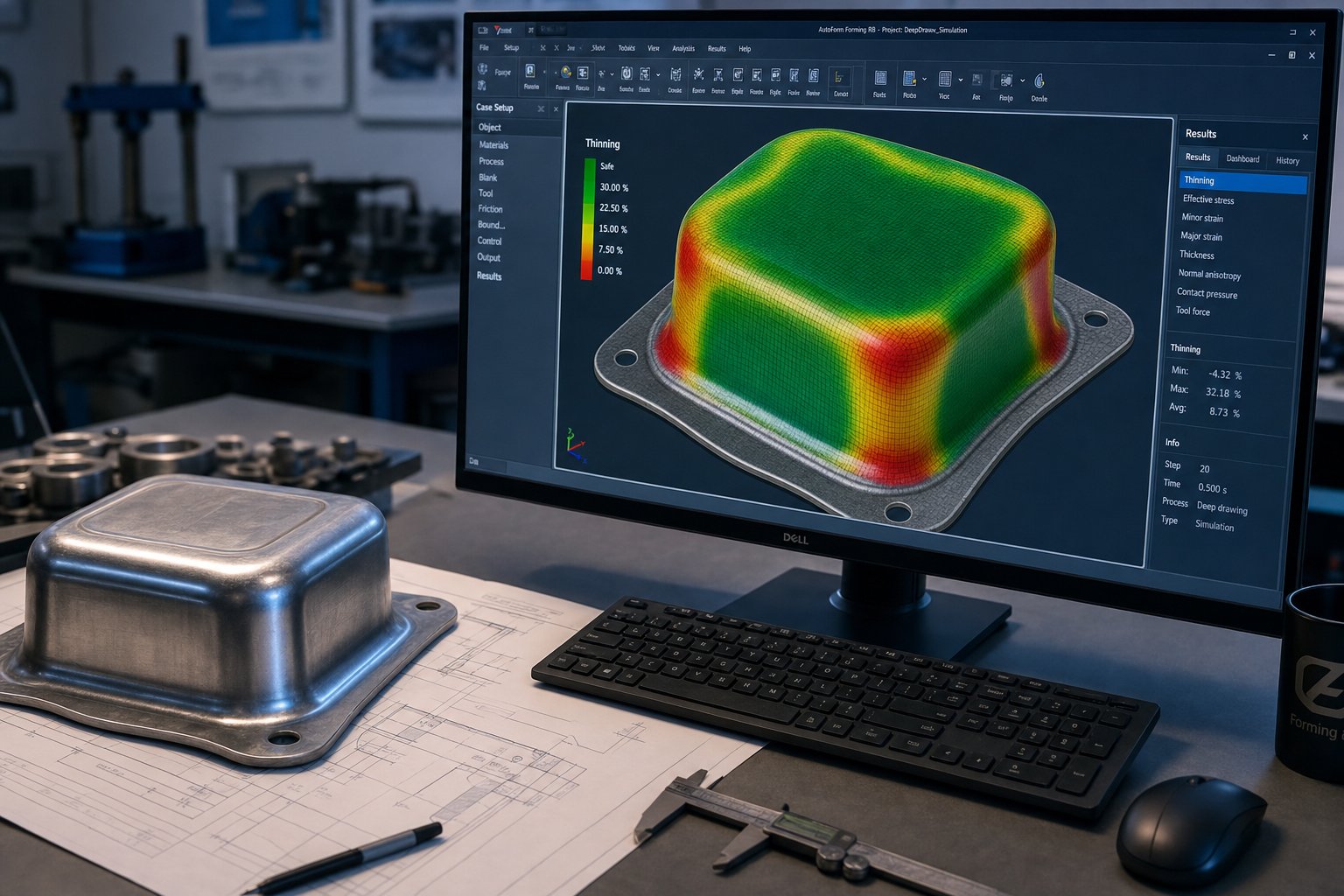
Rules of thumb get you to a feasible starting point. Simulation gets you to a validated design. Finite element analysis of the entire station sequence reveals problems that no manual calculation can predict: localized thinning between adjacent features, wrinkling in unsupported flange zones, or springback interactions between stations that compound into out-of-tolerance final dimensions.
According to Keysight's research on stamping simulation, virtual validation at the process engineering stage helps determine optimal blank shape, evaluate die face design, and predict draw-in behavior to ensure proper formability - all before physical tools are produced. This eliminates the expensive trial-and-error loops that plagued traditional die development.
A robust simulation workflow for transfer die and stamping projects follows this sequence:
- Model blank geometry and material properties (stress-strain curve, r-value, thickness)
- Define each station's tooling geometry, including punch, die, and blank holder surfaces
- Simulate each forming stage sequentially, carrying forward the strain history from prior stations
- Evaluate forming limit diagrams (FLD) at every station to check for necking or splitting risk
- Assess springback after each operation and at final release
- Iterate on die geometry, radii, or station count until all elements fall within safe forming limits
The critical insight is that simulation must model the cumulative effect of all stations, not just each station in isolation. A blank that survives station three with acceptable thinning may fail at station five because accumulated strain from earlier operations left insufficient ductility. This sequential dependency is what makes the progressive die stamping process simpler to simulate in some cases - the strip connection constrains material flow in predictable ways. Transfer die simulation must track a fully free workpiece through every repositioning and forming event.
For engineers specifying complex transfer die projects, suppliers that integrate simulation into the quoting phase can identify station count requirements, flag DFM issues, and propose geometry modifications before tooling investment begins. YICHEN's transfer stamping die engineering team supports this kind of DFM evaluation during early project stages, applying multi-station simulation to validate robotic transfer feasibility, forming sequences, and dimensional repeatability before committing to tool steel. This approach compresses development timelines and reduces the risk of costly mid-build design changes.
Simulation confirms whether your design is producible. The next question is whether it is economically justified - how many parts you need to stamp before the tooling investment starts paying for itself, and where the cost crossover sits relative to alternative manufacturing methods.
Production Volume Economics and Cost Planning
A producible design is only half the equation. The other half is whether you can justify the investment. Transfer die stamping demands significant upfront capital, and that capital only starts earning its return once production volume crosses a threshold that many projects never reach. Understanding where that threshold sits, and what drives it higher or lower, separates informed tooling decisions from expensive mistakes.
Volume Thresholds and Break-Even Thinking
Stamping economics revolve around amortization. A die that costs six figures produces parts at pennies each, but only if you run enough parts to spread that initial investment thin. For transfer dies specifically, the break-even point typically falls higher than progressive tooling because the total tool package involves multiple independent stations plus a transfer mechanism.
How high? It depends on part complexity and what you are comparing against. For parts currently produced through progressive stamping and fabrication methods like laser cutting, press braking, or welding, stamping becomes viable once annual volumes exceed roughly 10,000 to 20,000 units. Staub Manufacturing notes that advanced laser systems can now support 30,000 to 50,000 annual units cost-effectively, which means transfer die stamping needs to demonstrate clear per-piece savings beyond those thresholds to justify the tooling spend.
For simpler parts that could run in a high speed progressive die stamping setup, the calculus shifts further. A progressive die press running at 60-100+ strokes per minute drives per-piece cost down so aggressively that transfer tooling only wins when the part geometry makes progressive production physically impossible or when the progressive die itself becomes prohibitively complex.
Think of break-even not as a single number but as a range shaped by three variables: tooling cost, per-piece cost delta versus the alternative process, and annual volume commitment. A more expensive tool package needs either a larger cost delta or higher volume to amortize. A simpler transfer die with fewer stations breaks even sooner.
Tooling Cost Drivers and Lead Time Factors
What actually determines whether your transfer die package costs $100,000 or $500,000? The drivers stack in a predictable hierarchy. Here are the primary cost drivers listed in order of impact:
- Number of stations - Each independent station adds die steel, machining hours, and tryout time. A 12-station die costs roughly double what a 6-station die costs, not because each station is equally expensive but because cumulative complexity grows with count.
- Die complexity per station - A simple blanking station costs a fraction of a deep-draw station with nitrogen springs, cam-driven side actions, and precision-ground draw rings. Industry sourcing data shows that machining and complexity account for 30-50% of total die cost.
- Material grade of the die itself - Premium tool steels like SKD11 or solid carbide inserts for high-wear areas add 20-40% to material costs versus softer pre-hardened steels suitable for shorter runs.
- Tolerance requirements and surface finish - Class-A surface dies for visible automotive panels require extensive hand spotting and polishing. Structural parts with looser cosmetic requirements skip this labor-intensive step.
- Tryout and validation cycles - Testing the die in a press, adjusting timing, and verifying part dimensions typically adds 10-15% of total project cost. Complex geometries may require multiple tryout iterations.
Lead time follows a similar pattern. Standard transfer die projects run 8-16 weeks from design release to first article approval. Every added station extends this timeline because more tool steel must be machined, more components must be assembled, and more stations require individual verification before the full sequence can run. Projects requiring progressive die metal stamping services for the blanking operation plus a separate transfer die for forming add coordination time between tool builds.
Per-Piece Cost Comparison Across Methods
Once the die is built and validated, the per-piece economics of transfer stamping become compelling. Cycle times of 6-15 strokes per minute for complex parts (higher for simpler geometries) translate to throughput that fabrication cannot match. A part that takes 4 minutes to laser cut, form on a press brake, and weld from sub-components might take 4-8 seconds in a transfer die.
Consider how different methods compare at volume for a moderately complex drawn and pierced part:
- Fabrication (laser + press brake) - Low tooling investment, high per-piece cost. Economical below 5,000-10,000 units annually. Flexible for design changes.
- Single-hit dies - Moderate tooling cost per operation, but multiple setups and handling between operations inflate labor cost per piece. Viable for 5,000-30,000 units where geometry is simple.
- Progressive die stamping services - Lowest per-piece cost at very high volumes (500K+). A progressive stamping press running at high SPM amortizes its tool cost quickly, but the die itself is expensive and the geometry must be strip-compatible.
- Transfer die stamping - Higher tooling cost than single-hit, often lower than an equivalently complex progressive die. Per-piece cost drops below fabrication around 20,000-50,000 units depending on part complexity and station count.
The key insight is this: transfer dies occupy the economic middle ground between fabrication flexibility and progressive die efficiency. They serve complex parts at medium-to-high volumes where progressive tooling is geometrically impossible and fabrication is too slow. The per-piece cost advantage over fabrication grows with every unit produced, but the payoff only materializes if your volume forecast is accurate and stable.
Inaccurate volume projections are one of the most common sources of regret in stamping investments. Overestimating demand leaves expensive tooling underutilized. Underestimating it means you chose fabrication when stamping would have saved significantly over the product lifecycle. This uncertainty is why maintenance planning and die longevity matter just as much as the initial cost analysis - a die that wears prematurely or fails unexpectedly changes the entire economic picture.
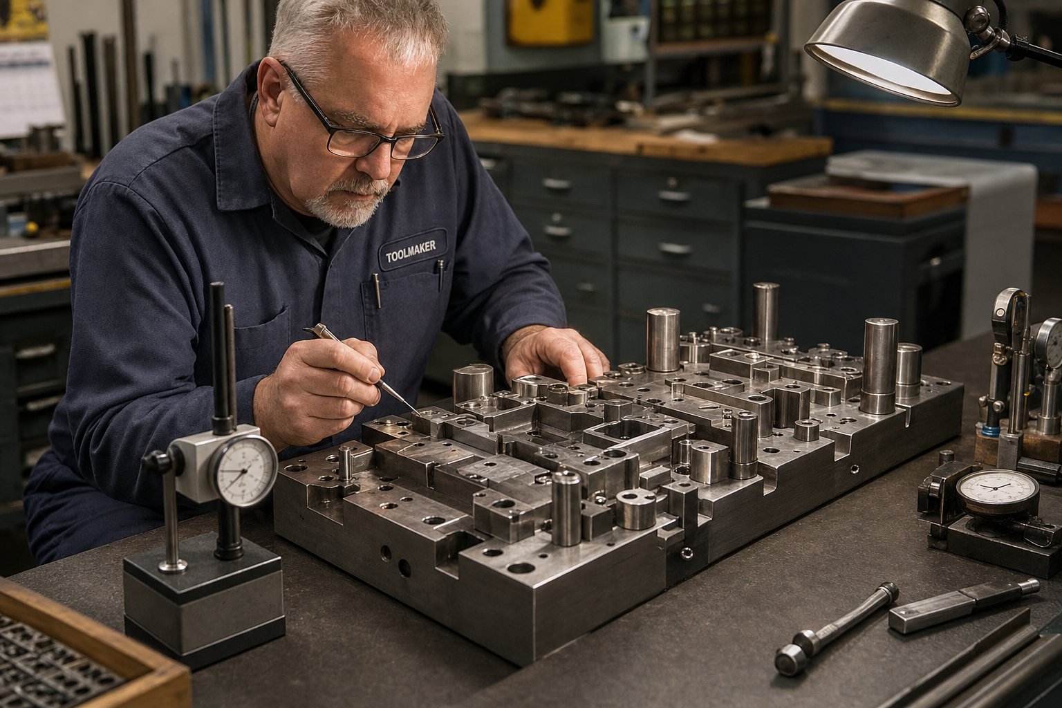
Tooling Maintenance and Troubleshooting Transfer Dies
A die that wears prematurely or fails mid-run does not just cost money to repair. It disrupts schedules, scraps material, and shifts the entire per-piece cost calculation that justified the tooling investment in the first place. Transfer die stamping adds a second maintenance domain on top of standard die care: the transfer mechanism itself. Grippers wear, timing drifts, and servo profiles degrade. Keeping both systems healthy requires distinct schedules and different inspection criteria.
Preventive Maintenance Schedules and Wear Indicators
Maintenance cadence for a transfer stamping press line splits into two categories: die components and transfer system components. Each follows its own rhythm because they wear at different rates and show different symptoms when they degrade.
Die component intervals:
- Every shift - Clear chips and slugs from die cavities, check lubrication flow to draw stations, visually inspect punch tips and cutting edges for obvious damage, and verify scrap paths are unobstructed.
- Weekly or per 50,000-100,000 strokes - Measure burr height on pierced features, check guide pin clearance with dial indicators, inspect stripper plates and nitrogen springs for fatigue, and record dimensional trends on critical part features using SPC data.
- Monthly or per 100,000-300,000 strokes - Regrind cutting edges when burr height exceeds specification, dress draw radii that show galling or pickup, verify die alignment and plate flatness, and replace worn locator pins or gauge blocks.
- Major overhaul at 70-80% of expected die life - Full teardown, dimensional audit of all wear surfaces, replacement of springs and fasteners, and re-qualification of the complete station sequence. Scheduling this preventive overhaul before end-of-life avoids mid-run failures that cause far more expensive unplanned downtime.
Transfer system intervals:
- Every shift - Inspect gripper fingers for wear, cracking, or misalignment. Verify finger closing force is consistent across all stations. Check that sensors detect part presence correctly at each position.
- Weekly - Measure transfer bar straightness and check for looseness in clamp mechanisms. Inspect servo drive feedback for position errors or following-error spikes in logged data.
- Monthly - Lubricate transfer rail bearings and ball screws. Check cam followers (on mechanical systems) for flat spots. Recalibrate part-presence sensors if reject rates have increased without visible die wear.
The key measurable indicators that trigger unscheduled maintenance on a die stamping press line include rising burr height, a narrowing bright shear band on cut edges, increased press tonnage per stroke (indicating dull cutting edges or friction buildup), and dimensional drift in SPC charts. On the transfer side, watch for increasing part misregistration, intermittent misfeed faults, and audible impacts during the placement phase that suggest timing or positional errors.
Common Failure Modes and Root Causes
Transfer die operations share some failure modes with progressive stamping but also introduce unique problems tied to the die transfer mechanism and the free-standing nature of the workpiece.
Misfeed and misregistration - When the blank arrives at a station slightly off-position, pierced holes shift, draw walls become uneven, and trim lines wander. The causes are almost always in the transfer system rather than the die itself. Gripper finger wear reduces clamping force, allowing the part to shift during acceleration. Timing drift in cam-driven systems moves the placement window relative to ram descent. Even changes in part weight, from material thickness variation lot to lot, can alter how the blank decelerates into its nest position.
Wrinkling in draw stations - Wrinkles form when compressive stress in unsupported flange areas exceeds the material's buckling resistance. In transfer dies, this often traces to blank holder force decay (worn nitrogen springs or hydraulic pressure loss), blank size variation from an upstream blanking operation, or lubricant inconsistency that changes the friction coefficient between the blank and the die surface. As stamping process experts note, too much wrinkling can also lead to splitting because wrinkled material must unwrinkle before flowing into the die cavity, restricting metal flow and causing excessive thinning.
Splitting and tearing - The opposite of wrinkling, splits occur when tensile stress exceeds the material's forming limit. Causes include insufficient lubrication, worn draw radii that create localized stress concentrations, or excessive blank holder force that restricts material flow. In a transfer die, splits also result from cumulative strain when upstream stations thin the material more than predicted, leaving insufficient ductility for later forming operations.
Die breakage - Punch tips fracture, die blocks crack, and inserts chip. Common root causes include overloading from mispositioned blanks, improper heat treatment of tool steel, slug pulling (where a blanked slug sticks to the punch and re-enters the die), and fatigue accumulation from repeated loading cycles without stress relief.
Surface finish degradation - Scratches, galling marks, and die lines appear when lubrication fails, die surfaces roughen from wear, or debris accumulates in draw cavities. Transfer dies are particularly susceptible because each station's die surface contacts a free blank that may carry particles from the previous operation.
Troubleshooting Framework for Transfer Die Issues
When a defect appears, the instinct is to adjust the die. But in transfer stamping, the root cause often lies elsewhere: in the transfer timing, the incoming material, or the press condition. A systematic symptom-to-cause approach prevents wasted effort on the wrong fix.
| Symptom | Probable Cause | Corrective Action |
|---|---|---|
| Part mispositioned at station (holes off-location, asymmetric walls) | Gripper finger wear; timing drift between transfer and press stroke; nest block wear | Replace worn fingers; recalibrate transfer timing to press crank angle; re-datum nest blocks |
| Wrinkling on drawn shells | Blank holder force decay (spring fatigue or hydraulic loss); blank oversized; lubricant excess in flange zone | Replace nitrogen springs or restore hydraulic pressure; verify blank dimensions; adjust lubricant application pattern |
| Splitting or tearing at draw radii | Worn or galled draw radius; insufficient lubrication; material lot variation (lower elongation); excessive blank holder force | Polish or regrind draw radii; restore lubrication flow; verify incoming material certification; reduce holder force incrementally |
| Dimensional drift (gradual, predictable) | Cutting edge wear increasing burr; guide pin clearance loosening; thermal expansion during long runs | Regrind edges per schedule; measure and replace guide pins; allow warm-up period or adjust die compensation |
| Intermittent misfeed faults (part not arriving at station) | Transfer finger closing force inconsistent; part sticking in previous station due to vacuum or galling; sensor misalignment | Adjust finger clamping mechanism; add air blow-off or lifter pins at sticky station; realign sensors |
| Punch or insert breakage | Slug pulling; mispositioned blank causing off-center loading; fatigue cracking from excessive strokes without maintenance | Add slug retention features (positive pressure, vacuum); fix upstream positioning issue; schedule stress relief or replacement at 70% life |
| Surface scratches or galling marks | Die surface roughening; debris in draw cavity; lubricant film breakdown; part dragging during transfer placement | Polish die surfaces; clean cavities each shift; change lubricant type or increase flow; adjust transfer placement height to avoid drag |
The most effective troubleshooting habit is separating die-related defects from transfer-related defects before taking action. A quick test: if the defect is consistent across every part in the same location, the die is likely the cause. If it is intermittent or varies in position from part to part, look at the transfer system, material variation, or press condition first. This distinction saves hours of misdirected adjustment and protects die surfaces from unnecessary rework.
Maintenance discipline and systematic troubleshooting protect your tooling investment over its full lifecycle. But even a perfectly maintained die cannot save a project that should not have used this process in the first place - which brings up the final, equally important question: how do you know whether transfer die stamping is the right choice for your specific application, and what should you look for in a partner who can help you make that call?
Knowing When to Use Transfer Dies and Choosing the Right Partner
Not every part belongs in a transfer die. The process delivers exceptional value for complex, medium-to-high volume applications, but forcing it onto the wrong project wastes capital, extends timelines, and produces parts that could have been made more efficiently another way. Being honest about when to walk away is just as important as knowing when to invest.
When Transfer Die Stamping Is Not the Right Fit
Several conditions signal that this process is the wrong tool for the job:
- Very low volumes (under 10,000 annually) - The tooling investment simply cannot amortize. A six-station transfer die costing $150,000-$300,000 produces parts at pennies each, but only if you stamp enough of them. Below 10,000 annual units, fabrication methods like laser cutting and press braking deliver the same part at lower total cost, even though per-piece pricing is higher.
- Extremely simple geometries - A flat bracket with two holes and a single bend does not need multiple independent stations. Progressive stamping dies handle this class of part faster and cheaper. If the geometry never requires the blank to be free-standing for forming, there is no reason to introduce transfer complexity.
- Ultra-thin foil materials (below 0.2 mm) - Foil stock lacks the rigidity needed for transfer fingers to grip and position accurately. The blank deforms under its own weight during transport, and even minor acceleration forces from the transfer bar cause wrinkling or positional errors. Progressive dies, which keep thin material supported on the carrier strip throughout, are the natural choice here.
- Parts requiring extremely high SPM - Transfer mechanisms introduce a motion cycle between each press stroke. Even the fastest servo-driven systems cap practical speeds well below what a progressive die achieves on the same press. If your annual volume demands 80+ strokes per minute to meet production targets, progressive die and stamping tooling is almost always the answer.
- Simple cylindrical draws with no secondary features - A plain cup with no piercing, flanging, or trimming can often run in a single-hit deep draw die with far less tooling investment. Transfer tooling earns its place when multiple operations must happen in sequence, not when one operation suffices.
The common thread: transfer die stamping solves multi-operation, geometrically complex problems at volume. Remove any of those three conditions and a simpler process likely wins.
What to Look for in a Transfer Die Partner
Choosing the right transfer die stampings suppliers matters as much as choosing the right process. Dies and stamping projects at this complexity level require partners who bring engineering depth, not just machining capacity. A shop that builds progressive stamping dies well does not automatically have the multi-station sequencing expertise, robotic integration experience, or simulation infrastructure that transfer projects demand.
When evaluating potential partners, prioritize these capabilities:
YICHEN exemplifies what this looks like in practice. Their engineering team supports multi-station forming evaluation, robotic transfer integration, and repeatability validation from the quoting stage forward, giving engineers a concrete resource for complex transfer die projects that require DFM collaboration before tooling commitment.
Beyond that specific example, your evaluation should cover:
- Multi-station design capability - Can the supplier design and build the entire station sequence in-house, or do they subcontract individual stations? Unified design control ensures consistent pass-line height, aligned shut heights, and coordinated timing across all tooling.
- In-house forming simulation - Suppliers who run FEA-based simulations before cutting tool steel catch thinning, wrinkling, and springback problems early. This directly reduces tryout cycles and compresses lead time.
- Robotic or servo transfer experience - Understanding transfer motion profiles, finger return paths, and interference clearances is specialized knowledge. A partner who has designed tooling for specific transfer system types can optimize station spacing and part orientation for maximum SPM.
- Tolerance verification methods - Ask how they validate dimensional conformance. CMM inspection at first article is standard, but strong partners also provide SPC data from tryout runs, GR&R studies for critical dimensions, and documented capability indices (Cpk) before production approval.
- DFM collaboration willingness - The best suppliers do not just build what you draw. They push back on features that inflate station count, suggest geometry modifications that improve formability, and propose material alternatives that reduce tonnage or springback challenges.
- Communication and project management structure - Transfer die projects involve multiple companies (press manufacturer, transfer system supplier, die builder, stamping plant). A partner with clear project management processes and responsive communication prevents the delays that accumulate when decisions stall between parties.
Red flags include suppliers who quote without asking about your transfer system specifications, who cannot explain their station sequencing logic, or who have no simulation capability and rely entirely on physical tryout. These gaps translate directly into longer lead times, more tryout iterations, and higher total project cost.
Project Specification Checklist for Engineers
Before you send an RFQ to any transfer die supplier, assemble these items. Incomplete specifications lead to inaccurate quotes, misaligned expectations, and mid-project scope changes that inflate cost:
- Complete part drawing - 3D CAD model plus 2D print with full GD&T callouts. Include all critical-to-function dimensions explicitly flagged.
- Material specification - Grade, temper, thickness, and any directional requirements (grain orientation relative to forming direction).
- Annual volume and batch size - Total annual demand, typical order quantities, and projected product life in years. This determines die life requirements and maintenance intervals.
- Tolerance requirements - Specify which dimensions require Cpk verification and what capability indices are acceptable (1.33, 1.67, or higher).
- Surface finish requirements - Identify cosmetic surfaces, acceptable mark depths, and any post-stamping finish requirements (painting, plating, powder coating) that affect how aggressively the die can contact the part.
- Secondary operations - List any post-stamping work (welding, tapping, assembly, heat treatment) so the die designer can account for datum features and handling surfaces.
- Press and transfer system specifications - Tonnage, bed size, stroke length, shut height, transfer type (servo or mechanical), pitch range, lift height, and clamp distance. If the press is not yet selected, state that explicitly.
- Sample parts or prototypes - Physical samples, foam models, or 3D-printed representations help suppliers assess handling and orientation challenges that drawings alone may not convey.
- Quality and certification requirements - ISO 9001, IATF 16949, or industry-specific standards the supplier must hold.
This checklist is not bureaucratic overhead. Each item directly affects how the die is designed, how many stations are needed, and what the tooling will cost. Missing even one element, especially the transfer system specifications, can force a redesign after the project is already underway. A complete package up front is the single most effective way to get an accurate quote, a realistic timeline, and a die that produces conforming parts from the first production run.
Transfer Die Stamping FAQs
1. What is the difference between transfer die stamping and progressive die stamping?
The core difference lies in how the workpiece moves through the die. In progressive stamping, the part stays attached to a continuous metal strip throughout all forming operations. In transfer die stamping, the blank is separated from the coil early, then a mechanical or servo-driven transfer system lifts and carries it between independent die stations. This separation gives transfer dies the ability to handle larger parts, deeper draws, and multi-axis geometries that would be impossible to form while the material remains on a strip. Progressive dies typically run faster and suit high-volume small parts, while transfer dies serve medium-to-high volume complex parts that need free-standing forming.
2. What types of parts are best suited for transfer die stamping?
Transfer die stamping works best for parts that share three characteristics: geometric complexity, medium-to-large size, and production volumes above roughly 20,000 units annually. Specific examples include deep-drawn automotive structural brackets, large appliance housings, multi-axis formed panels, and parts requiring operations on both sides of the workpiece. Parts needing multiple redraw stages, heavy flanging, or features formed from different directions benefit most because the free-standing blank can be repositioned between stations. Simple flat parts with minimal forming or very small components are better served by progressive dies or single-hit tooling.
3. How many stations does a typical transfer die require?
Most transfer die projects use between 4 and 12 independent stations, though the exact count depends on part complexity, draw depth, and the number of secondary features like pierced holes or flanges. A simple drawn shell with trimming might need only 4-5 stations, while a complex automotive panel with multiple redraws, piercing, bending, and coining could require 10-12. Each additional station adds roughly 8-15% to tooling cost and requires more press bed length. Suppliers like YICHEN use forming simulation during the quoting phase to determine optimal station count before committing to tool steel, helping engineers balance formability requirements against cost constraints.
4. What production volume makes transfer die stamping cost-effective?
The break-even point for transfer die stamping typically falls between 20,000 and 50,000 annual units when compared to fabrication methods like laser cutting and press braking. However, this threshold shifts based on part complexity, station count, and the alternative process being displaced. Simpler parts with fewer stations break even sooner, while complex dies with 10+ stations need higher volumes to amortize the investment. For parts that could theoretically run in a progressive die, transfer tooling only makes economic sense when the geometry is physically incompatible with strip-based forming or when the equivalent progressive die would be prohibitively complex.
5. How do you choose between servo-driven and mechanical transfer systems?
The choice depends on your production mix, changeover frequency, and part characteristics. Mechanical cam-driven systems tie all motions to a fixed press crank angle, making them reliable and robust for dedicated lines running one part family for years. Servo-driven systems offer programmable motion profiles that allow operators to adjust travel distances, accelerations, and timing digitally. This makes them ideal for facilities stamping multiple part numbers on shared presses, handling asymmetric or varying-weight parts, or targeting maximum strokes per minute through motion overlap optimization. Servo systems also reduce changeover time significantly since new profiles load digitally rather than requiring physical cam swaps.


