


What a Progressive Stamping Die Actually Is
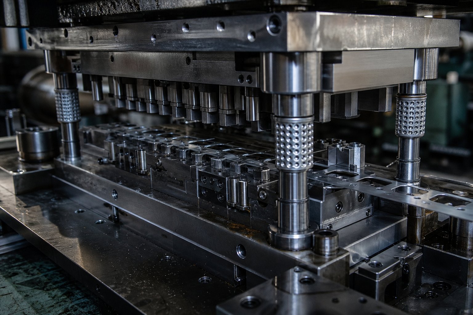
A progressive stamping die is a precision-engineered tool, a physical piece of specialized equipment, that performs multiple metalforming operations in sequence as a metal strip advances through a series of stations. Each station inside the die executes a specific task such as cutting, bending, or forming. By the time the strip reaches the final station, a completed part is separated and ejected.
A progressive stamping die is a custom multi-station tool installed in a stamping press that transforms flat metal coil stock into finished parts through coordinated cutting, bending, and forming operations, all within a single die set.
Sounds straightforward, but there is one point of confusion worth clearing up immediately.
The Die Is the Tooling Not the Process
People often use "progressive die" and "progressive die stamping" interchangeably. They are not the same thing. The progressive die is the physical tooling, a block of hardened steel containing punches, cavities, and forming features engineered for a specific part. Progressive stamping is the manufacturing process that uses this tool inside a press to produce parts at scale. Think of it this way: the stamping die is the instrument, and progressive stamping is the operation performed with it.
Why does this distinction matter? Because when you are evaluating tooling costs, lead times, or supplier capabilities, you need to know whether the conversation is about designing and building the tool itself or running the production process. They carry very different timelines, budgets, and engineering decisions.
How the Progressive Die Fits Into Manufacturing
So what is a progressive die designed to accomplish? It exists to enable high-volume, repeatable production of complex metal parts without manual handling between operations. A coil of sheet metal, whether steel, aluminum, or copper, feeds into the press. The strip advances through the die at a precise fixed increment with every press stroke. Each station performs its designated operation, and one finished part exits the die with every cycle. Presses can run anywhere from 25 to 200 strokes per minute or more, which makes progressive stamping ideal for producing thousands to millions of identical components annually.
This combination of speed, consistency, and automation is why progressive dies dominate industries like automotive, electronics, HVAC, and consumer goods. The entire value proposition hinges on one thing: the quality and precision of the die itself. Every tolerance, every surface finish, every dimensional outcome traces back to how that tool was designed and built, which raises an important question about what actually goes on inside one of these dies.
Anatomy of a Progressive Die and Its Key Components
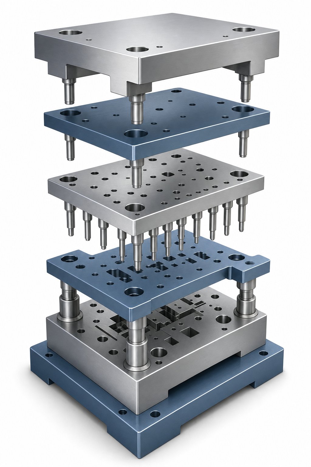
Every progressive die is a stamping die set split into two halves: an upper assembly (mounted to the press ram) and a lower assembly (bolted to the press bed). These halves open and close with each stroke, and every component inside them has a specific job. Miss one piece or get its fit wrong, and the entire system fails. Here is what you will find inside progressive stamping dies when you break them down layer by layer.
Structural Components That Hold Everything Together
The foundation of any stamping die set is the die shoe, a heavy steel or aluminum plate that serves as the mounting base for both halves. The upper die shoe carries the punch assembly, while the lower die shoe supports the die block and its inserts. These shoes absorb impact forces stroke after stroke and keep everything registered in position.
Attached to the upper shoe is the punch plate, which holds the cutting and forming punches in precise alignment. Directly beneath that sits the backing plate, a hardened steel slab that distributes punch forces evenly across the shoe. Without it, hardened punch inserts would gradually press into the softer shoe material and shift out of position. As Wisconsin Metal Parts explains, the back-up plate protects the tool because hardened inserts would otherwise push into the softer die set under repeated impact.
Working Components That Shape the Metal
The die block sits in the lower assembly and contains the cutting cavities, forming pockets, and die buttons that pair with the upper punches. Die buttons provide the opposite cutting edge for each punch and are typically offset larger than the punch nose by 5-10% of the material thickness to create proper shear clearance.
The stripper plate is one of the most critical stamping die components. It performs two essential functions: clamping the material flat against the die block during operations, and stripping the stock off the punches on the upstroke. Without it, material would stick to the punches, pull upward, and jam the die. Springs, either mechanical coil or nitrogen gas, power the stripper plate and also provide the pressure needed for forming pads and stamping die lifters that raise the strip for feeding between strokes.
Retainers hold the punches and buttons securely inside their respective plates. Ball-lock, shoulder, and trumpet-head styles each offer different advantages for accessibility during maintenance. High-volume progressive dies often use inserted cutting and forming stations rather than single-piece die blocks, which makes replacement faster if an insert chips or wears.
Alignment and Registration Systems
Precision in progressive dies depends on two alignment systems working together. Guide posts and bushings align the upper and lower die shoes with each stroke. These are manufactured to tolerances within 0.0001 inches and typically use ball-bearing cages for smooth, repeatable motion.
Pilot pins handle a different job: registering the strip position at each station. Their bullet-nose shape enters pre-pierced holes in the stock strip and settles it into an exact location before any operation executes. This ensures holes, edges, and forms land precisely where the part print requires them, compensating for any slight feed inaccuracy.
The table below maps each component to its location and role within the stamping die set:
| Component | Location | Function |
|---|---|---|
| Die Shoe (Die Set) | Upper and lower foundation | Mounts all components; absorbs press forces |
| Punch Plate | Upper assembly | Holds cutting and forming punches in alignment |
| Backing Plate | Between punch plate and upper shoe | Distributes impact forces; protects die shoe |
| Die Block / Die Chase | Lower assembly | Contains cutting cavities, forming pockets, and inserts |
| Stripper Plate | Below punch plate, contacts strip | Clamps material flat; strips stock off punches |
| Guide Posts and Bushings | Corners of die set | Aligns upper and lower halves within 0.0001" |
| Pilot Pins | Upper assembly, entering strip holes | Registers strip position precisely at each station |
| Die Springs (Mechanical/Nitrogen) | Upper and lower assemblies | Powers strippers, pressure pads, and stamping die lifters |
| Retainers | Punch plate and die block | Secures punches and buttons in position |
| Stop Blocks | Lower assembly edges | Sets press shut height; aids die timing |
Every one of these stamping die components must work as an integrated system. The upper and lower halves need to align within microns across thousands of strokes per hour. A misalignment between guide posts shifts punch-to-die clearance, which immediately shows up as burrs, dimensional drift, or broken tooling. That system-level precision is what separates a well-built progressive die from one that causes constant production headaches.
Understanding what is inside the die is one thing. Seeing how the strip actually moves through it, station by station, reveals why the sequence of operations matters just as much as the components themselves.
How a Progressive Die Works Station by Station
Imagine a coil of flat metal stock, weighing hundreds or even thousands of pounds, mounted on an uncoiler behind the press. A servo feeder grips the leading edge of the strip and pushes it into the die at a precise, repeating distance with every press stroke. That fixed increment is called the progression distance, and it is the heartbeat of the entire die process. Every station inside the die is spaced at exactly this interval, so when the strip advances one pitch, each station receives a fresh section of material to work on simultaneously.
How the Metal Strip Feeds and Advances
The progressive stamping process starts well before the metal enters the die. A coil cradle or uncoiler pays out the strip, which passes through a straightener to remove the natural curl from being wound on a reel. The strip then reaches the servo feeder, a programmable unit that advances the material by the exact progression distance, typically accurate to within +/-0.025 mm. This feed accuracy is critical because even a small positional error would compound across multiple stations and ruin the part.
How does a stamping press work with this feed system? The press ram cycles up and down at a set speed, measured in strokes per minute (SPM). During the open portion of each stroke, the feeder advances the strip. During the closed portion, the upper die descends, operations execute, and the strip stays locked in place. This synchronized rhythm between press and feeder keeps the progressive die stamping process running continuously without interruption.
Between strokes, pilot pins descend into pre-pierced holes in the strip before any cutting or forming tools make contact. These tapered pins nudge the material into its exact theoretical position, correcting any minor feed error. This pilot registration system resets the strip to zero with every cycle, which is why progressive dies can hold tight tolerances even at high speeds on a progressive stamping press.
Cutting Operations Inside the Die
The first several stations in most progressive dies handle cutting operations. These remove material to create holes, slots, and part profiles before any forming takes place. Each cutting station within the stage tooling handles a specific task:
- Piercing - Punches cut internal holes and openings by shearing through the strip. The slugs fall through die openings below. Pilot holes are typically pierced at the very first station to provide registration for all subsequent operations.
- Blanking - Cuts the external perimeter of the part. In progressive dies, blanking often happens in stages across multiple stations, removing sections of the perimeter progressively rather than all at once.
- Lancing - Creates partial cuts where the material is cut on some edges but remains attached on others. Lancing forms tabs, louvers, or relief areas that will later be bent or formed out of the strip plane.
- Notching - Removes material from the strip edges to create clearance for upcoming forming operations or to define part outlines.
Cutting operations come first for a practical reason: forming bends or draws near a hole can distort that hole if the hole was not punched beforehand while the metal was still flat and fully supported.
Forming Operations and Final Cutoff
After cutting stations establish the flat profile, forming stations transform the two-dimensional shape into a three-dimensional part. Each forming station applies only an incremental change, allowing the material to deform gradually without cracking or tearing:
- Bending - Angular forming that creates flanges, channels, or brackets. Bend stations use punch-and-die geometry to fold material along a defined line.
- Coining - A compression operation that thins or flattens material in a controlled area. Coining mfg techniques apply very high localized pressure to achieve precise thickness control, create lettering, or sharpen bend radii.
- Embossing - Produces shallow raised or recessed features, such as stiffening ribs, logos, or identification marks, without fully cutting through the material.
- Drawing - Deep forming that pulls material into a cavity to create cup-shaped or recessed geometries. Drawing stations often require multiple progressive hits to reach final depth without tearing the strip.
The final station performs the cutoff, which separates the finished part from the carrier strip entirely. The completed component drops through the die or exits via a chute, while the remaining skeleton scrap advances out the back of the press for recycling.
Here is the complete progressive stamping process in sequence from start to finish:
- Coil stock unwinds and feeds through a straightener.
- Servo feeder advances the strip by one progression distance into the die.
- Pilot pins engage pre-pierced holes, locking the strip into position.
- Piercing stations punch pilot holes, internal features, and slots.
- Notching and lancing stations remove edge material and create partial-cut tabs.
- Blanking stations progressively cut sections of the part perimeter.
- Bending stations form angles and flanges.
- Coining or embossing stations refine thickness, add features, or sharpen details.
- Drawing stations create any deep-formed geometry.
- Cutoff station separates the finished part from the strip.
- Finished part ejects; skeleton scrap advances and is collected for recycling.
Every one of these steps happens simultaneously at different points along the strip with each press stroke. Station one pierces a fresh section while station five bends a section that entered the die four strokes ago and station ten cuts off a completed part. That parallel execution is what makes the progressive die stamping process so fast: one finished part exits the die with every single stroke of the press, regardless of how many operations the part requires.
The sequence of stations is not arbitrary. It follows engineering logic that balances material flow, force distribution, and geometric accuracy. How engineers determine that sequence, optimize material usage, and validate the design before any steel is cut is its own discipline entirely.
Progressive Die Design Principles and Strip Layout
Every progressive stamping tool starts as a part print, a 2D or 3D engineering drawing showing the finished component's geometry, tolerances, and material call-out. Getting from that print to a hardened, assembled die ready for production is a structured engineering workflow that determines everything downstream: cycle speed, material cost, part quality, and tooling lifespan. Progressive die design is where manufacturing success or failure gets locked in.
Strip Layout Development and Material Utilization
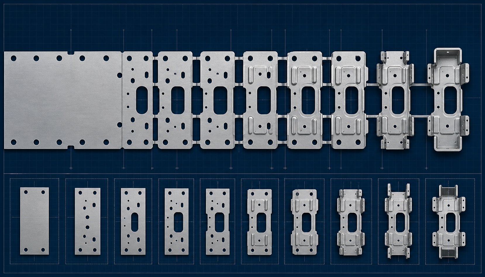
The first major engineering decision is the strip layout. How should the part be oriented within the strip, and how many stations will it take to complete all operations? Engineers start by unfolding any bent or formed features back into a flat blank shape, then test multiple orientations on the strip to find the arrangement that wastes the least material while keeping the strip mechanically stable during feeding.
Material utilization, expressed as a percentage of the strip area that becomes usable parts versus scrap, is a primary design target. A well-optimized progressive stamping die design can reach 70-85% material utilization for simple geometries, though complex shapes with large flange areas may drop below 60%. Even a few percentage points of improvement matter at scale: producing one million parts per month from 0.3mm stainless steel, a 15% reduction in scrap can save thousands of dollars monthly in raw material alone.
Between each part on the strip, engineers design scrap bridges, the thin bands of material that connect adjacent stations and maintain strip integrity as it feeds through the die. These bridges must be wide enough to resist tearing under feed forces and forming stresses, but narrow enough to minimize wasted material. Carrier style (unilateral, bilateral, or intermediate) depends on part geometry, material thickness, and how many forming operations require support.
Station Sequencing Logic and Engineering Decisions
Station sequencing is not just arranging operations left-to-right. It follows strict engineering logic rooted in how metal behaves under deformation:
- Pierce before bending near holes - Holes punched while the material is flat maintain their geometry. Bending after piercing avoids distorting those features.
- Notch and lance before forming - Removing material adjacent to bend zones before forming allows metal to flow freely without cracking.
- Form before cutoff - The carrier strip provides rigidity during forming. Separating the part too early leaves it unsupported and prone to dimensional shift.
- Coin or shape after initial bending - Shaping stations refine geometry and tighten angular tolerances after the primary form is established.
Engineers also determine where to place empty stations, gaps with no tooling, to provide structural room for robust die inserts or to allow future design modifications without rebuilding the entire tool. As detailed in multi-station layout methodology, empty stations also help maintain die strength when step spacing is small, typically below 8mm.
From Simulation to Finished Die Assembly
Before any steel is cut, progressive die design software validates the entire forming sequence through finite element analysis (FEA). Simulation reveals thinning, cracking risk, springback, and material flow issues at each station. Engineers iterate on punch radii, draw depths, and blank holder pressures virtually, avoiding costly rework during physical tryout.
Once the design is validated, the build process follows a precise sequence:
- CNC machining - Mills die shoes, punch plates, and die blocks to near-net shape.
- Wire EDM - Cuts intricate punch and die profiles to tolerances within 0.002mm.
- Surface grinding - Achieves flatness across mating surfaces, critical for even strip clamping.
- Heat treatment - Hardens tool steel components (typically to 58-62 HRC) for wear resistance.
- Assembly - Fits all components into the die set, verifies alignments, and sets timing.
- Tryout (T1-T3) - Runs initial samples in the press, measures parts, and adjusts until dimensions meet print specifications.
Achievable tolerances from a well-built progressive stamping tool depend on part geometry, material, and die construction quality. Standard metal stamping die design typically holds positional tolerances of +/-0.05mm to +/-0.10mm, while high-precision applications with carbide inserts and tight die clearances can reach +/-0.005mm on critical dimensions. Angular tolerances generally fall within +/-0.5 degrees for standard bends.
A complete progressive die, from initial stamping die design concept through validated T3 samples, typically requires 12 to 20 weeks. That timeline reflects the engineering intensity behind each tool: the strip layout, the sequencing logic, the simulation, the precision machining, and the iterative tryout process that proves the design works at production speed. Every decision made during this phase directly shapes how the die performs over millions of cycles, which brings up the question of what materials those millions of parts will be made from.
Materials Suited for Progressive Die Stamping
The metal strip feeding through a progressive die is not a passive passenger. Its mechanical properties, how it stretches, how it resists tearing, how it springs back after bending, directly dictate how many stations the die needs, what clearances the punches require, and whether the finished part will hold tolerance. Choosing the wrong progressive stamping materials does not just produce bad parts. It damages the die itself.
Common Metals and Their Progressive Stamping Characteristics
Not every metal responds well to high-speed multi-station forming. The best candidates for progressive metal stamping share a few traits: consistent thickness, predictable elongation, and stable mechanical properties across a coil. Here is how the most common material families perform:
- Low-carbon steel (C1008-C1020) - The most widely used material in progressive die metal stamping. Low-carbon steel offers excellent formability, high elongation (typically 25-40%), and low cost. It bends cleanly, pierces with minimal burr, and tolerates aggressive forming without cracking. Carbon steel progressive stamping dominates applications in automotive brackets, HVAC components, and construction hardware.
- Stainless steel (300 and 400 series) - Chosen for corrosion resistance in food handling, medical, and marine environments. However, stainless work-hardens rapidly during forming, which means the metal stamping die must apply higher forces and the strip may need more stations to achieve the same geometry incrementally. Die clearances are typically tighter (around 3-5% of material thickness) to control burr.
- Aluminum alloys (3003, 5052, 6061) - Lightweight and conductive, aluminum progressive stamping serves aerospace, electronics, and thermal management applications. Aluminum is soft but gummy, meaning it tends to adhere to punch surfaces and cause galling. Dies running aluminum often require polished tool surfaces, PVD or DLC coatings, and careful lubrication to prevent material pickup.
- Copper - Prized for electrical and thermal conductivity, copper progressive stamping produces busbars, terminals, and heat exchanger components. Copper is highly ductile but soft, which means punches can leave burrs if clearances are not optimized. Its tendency to stick to tooling makes coated punches a near-requirement at production speeds.
- Brass (C26000, C27400) - An alloy of copper and zinc, brass progressive stamping delivers excellent formability combined with natural corrosion resistance. Brass machines cleanly, produces minimal burr, and is widely used for connectors, decorative hardware, and plumbing fittings. Its forgiving nature makes it one of the easier non-ferrous metals to stamp at high speed.
- High-strength low-alloy steel (HSLA) - Used in automotive structural components where weight savings and crash performance matter. HSLA grades require significantly more tonnage to form and cause faster punch wear, which means dies need carbide inserts and more robust backing plates to handle the forces.
| Material | Typical Applications | Formability | Special Die Considerations |
|---|---|---|---|
| Low-carbon steel | Brackets, clips, HVAC parts, hardware | Excellent | Standard clearances (5-10% of thickness); minimal lubrication needed |
| Stainless steel | Medical, food equipment, marine | Moderate | Tighter clearances (3-5%); higher press tonnage; TiN or DLC coatings recommended |
| Aluminum alloys | Electronics enclosures, heat sinks, aerospace | Good | Polished punch surfaces; anti-galling coatings; controlled lubrication |
| Copper | Busbars, terminals, connectors | Excellent | Coated punches; tight clearances to control burr on soft material |
| Brass | Connectors, valves, decorative hardware | Very good | Minimal special requirements; standard tooling often sufficient |
| HSLA steel | Automotive structural, safety components | Limited | Carbide inserts; higher tonnage press; more forming stations for incremental bends |
Thickness Ranges and Formability Considerations
Progressive dies handle strip thicknesses from as thin as 0.1 mm (common in electronics connectors) up to approximately 6 mm for heavy structural brackets. The sweet spot for most high-speed progressive stamping falls between 0.3 mm and 3.0 mm, where feed systems maintain accuracy and forming forces stay within standard press capacities.
Three material properties drive station design more than any others:
- Elongation percentage - Measures how far the metal stretches before fracturing. Higher elongation (above 20%) allows tighter bend radii and deeper draws in fewer stations. Low-elongation materials need more gradual, multi-station forming to avoid cracking.
- Tensile strength - Determines the force required to shear and form the strip. Higher tensile strength increases tonnage demands and accelerates punch wear.
- Yield strength - Defines when the metal permanently deforms. A large gap between yield and tensile strength (the plastic range) gives the die engineer more room to form complex shapes without fracturing the material.
Harder, stronger progressive stamping materials like stainless steel or HSLA grades push die design toward more stations, heavier press frames, and premium tool steels. Softer metals like brass and copper allow faster cycles and simpler tooling, but demand surface treatments to prevent adhesion. Every material choice cascades into tooling cost, press selection, and maintenance intervals, which means the decision is never about the metal alone. It is about how that metal interacts with the die type chosen to form it.
Progressive Dies vs Transfer Dies vs Compound Dies
Different part geometries, production volumes, and size constraints call for different types of stamping dies. A progressive die is one option in a broader family of die stamping tools, and knowing where each type excels helps you avoid over-investing in tooling that does not match your application. Here is how the four major die types compare, what each does best, and when to choose one over the others.
Progressive Die vs Transfer Die vs Compound Die
Each die type solves a fundamentally different manufacturing problem. Before comparing them side by side, you need a clear definition of what each one actually does:
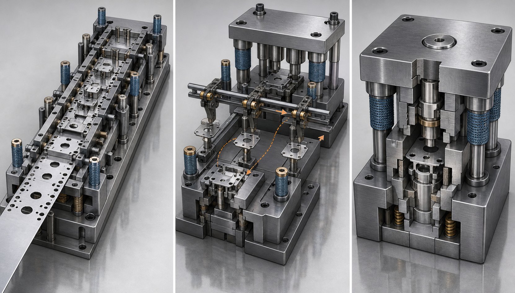
- Progressive die - A multi-station tool where the metal strip remains connected to the coil throughout. The strip advances one pitch per stroke, and each station performs a different operation (piercing, bending, forming) until the final station cuts the finished part free. One completed part exits every stroke.
- Transfer die - Individual blanks or partially formed parts are mechanically transferred from station to station by gripper fingers or rails. The part is separated from the strip early (or fed as pre-cut blanks) and moved independently between die stations mounted in the same press. Transfer die stamping handles larger or more complex parts that cannot remain attached to a carrier strip.
- Compound die - Performs multiple cutting operations simultaneously in a single press stroke. Blanking and piercing happen at the same time within one station, producing a flat finished part with tight concentricity between internal and external features. Compound die stamping is limited to flat geometry but delivers superior positional accuracy.
- Single-stage die - Executes one operation per stroke: a single pierce, a single bend, or a single blank. Parts move between separate dies and presses (or the same press with die changes) to complete all required operations. Simple, low-cost tooling suited for prototypes or very low volumes.
The differences become much clearer when you compare them across the criteria that actually drive tooling decisions.
Decision Criteria for Selecting the Right Die Type
Imagine you have a part print, a volume target, and a budget. Which die type fits? The answer depends on six factors working together:
| Criteria | Progressive Die | Transfer Die | Compound Die | Single-Stage Die |
|---|---|---|---|---|
| Part complexity | High (multi-operation: pierce, bend, form, draw) | Very high (allows part rotation, tipping, and complex 3D forming) | Low to moderate (flat parts with multiple cut features) | Low (one feature per operation) |
| Production volume suitability | High volume (100,000+ parts/year) | Medium to high volume | Medium volume | Low volume or prototyping |
| Material waste | Moderate (carrier strip becomes scrap) | Low (blanks can be nested for higher utilization) | Low to moderate | Varies by operation |
| Tooling cost | High (many stations, precision components) | High (multiple die stations plus transfer mechanism) | Moderate (single station, complex internals) | Low (simple, single-purpose tool) |
| Cycle speed (parts/min) | Very fast (30-200+ SPM typical) | Moderate (15-40 SPM typical) | Moderate to fast (depends on press) | Slow (manual handling between operations) |
| Part size limitations | Small to medium (must fit within strip width, typically under 300 mm) | Medium to large (no strip-width constraint) | Small to medium (flat geometry only) | Any size |
A few patterns emerge from this comparison. Progressive dies dominate when you need complex, small-to-medium parts at high volumes with maximum cycle speed. The strip stays connected throughout, which eliminates part-handling equipment between stations and keeps speeds high. As MetalForming Magazine notes, progressive dies can produce multiple parts per stroke with potentially high material utilization and run at relatively high speeds, often making them the best solution for high-volume production.
Transfer dies step in where progressive dies hit their limits. When a part is too large to remain on a carrier strip, when it needs to be rotated or flipped between operations, or when material utilization can be improved by nesting blanks rather than feeding a continuous coil, transfer die stamping becomes the better path. Transfer dies also offer easier serviceability and adjustment at individual stations because each die section is more accessible than a tightly packed progressive tool.
Compound die stamping occupies a narrower niche. When you need a flat part, think washers, gaskets, electrical laminations, where the internal holes must be perfectly concentric with the outer profile, a compound die achieves that in one stroke. Everything cuts simultaneously, so there is zero positional drift between features. The tradeoff is that compound dies cannot perform bending, drawing, or any forming operation.
Single-stage dies are the baseline. They cost the least per tool but the most per part at volume because every operation requires a separate press cycle and often manual part handling. They make sense for prototypes, bridge production, or parts that genuinely need only one operation.
Here is a practical decision framework to simplify the choice:
- If the part fits within strip-width constraints (typically under 250-300 mm), requires multiple operations, and annual volume exceeds 100,000 pieces, a progressive die is almost always optimal.
- If the part is too large for a strip, needs rotation between stations, or material utilization benefits from blank nesting, consider a transfer die.
- If the part is flat with critical concentricity between punched features and moderate volume, a compound die delivers the tightest feature-to-feature accuracy.
- If volume is low, geometry is simple, or you are validating a design before committing to production tooling, single-stage dies and stamping keep upfront investment minimal.
Die stamping decisions are rarely about one factor alone. Volume justifies tooling cost. Part size dictates strip feasibility. Geometry determines whether the part can stay on a carrier or must be transferred independently. When all three factors align toward a progressive die, the per-part economics at scale are hard to beat, but understanding the alternatives ensures you are not forcing a part into the wrong dies and stamping approach.
That per-part economics argument raises an important follow-up: if progressive dies deliver the lowest cost per piece at volume, what actually drives their upfront tooling investment so high?
What Drives Progressive Die Tooling Cost
Progressive die tooling is expensive. A straightforward bracket die might start around $15,000, while a complex multi-station tool with tight tolerances and carbide inserts can exceed $100,000. Those numbers surprise people who have only priced CNC machined or laser-cut parts. But the cost is not arbitrary. Every dollar traces back to specific engineering and manufacturing decisions that determine how many parts the die can produce, how fast it runs, and how long it lasts before needing rework.
Key Factors That Determine Die Tooling Cost
Several variables interact to set the final price of progressive tooling. Some carry more weight than others. Here they are, ranked roughly by impact on total cost:
- Number of stations - Each station adds machined punches, die inserts, stripper openings, and backing plate pockets. A 6-station die has roughly half the machined components of a 12-station die, which translates directly into less CNC time, less wire EDM time, and less assembly labor. Parts with difficult geometry or tight tolerances increase the number of stations necessary, driving cost upward.
- Part complexity and tolerance requirements - Complex contours require wire EDM cutting at tolerances within 0.002 mm. Tight positional specs demand precision grinding, careful tryout iterations, and potentially multiple sample runs (T1, T2, T3) to dial in the die. Each tryout round costs press time, material, and engineering hours. A part with +/-0.05 mm on critical features may need three or four tryout cycles, while a part holding +/-0.2 mm might pass on the first run.
- Die material grade - Tool steel selection directly affects both cost and lifespan. Standard D2 or A2 tool steel is the baseline for most progressive stamping dies. High-volume applications or abrasive materials like stainless steel or HSLA grades warrant solid carbide inserts or powdered metal steels like CPM-10V, which cost significantly more to purchase and require specialized machining. As die engineering experts note, high production volumes warrant higher-quality tool steel sections, alternative materials like solid carbide, and longer-life gas springs, all of which take more time and cost more to manufacture.
- Production volume expectations (die classification) - A die expected to run 50 million strokes gets built differently from one targeting 500,000. High-volume Class A dies use thicker die shoes, hardened guide systems, carbide cutting stations, and premium springs. Low-volume Class B or Class C dies may use softer steels, simpler spring systems, and fewer backup components. The upfront difference can be 2-3x, but the cost per stroke over the die's lifetime drops dramatically with robust construction.
- Delivery timeline - Compressed schedules force overtime and may require expedited material procurement. A standard 12-16 week build allows efficient scheduling across CNC, grinding, EDM, and assembly departments. Cutting that to 6-8 weeks typically inflates tooling cost by 15-25% because the die shop must reprioritize other work.
These factors do not operate independently. A part with complex geometry naturally requires more stations, tighter die materials, and additional tryout cycles. That compounding effect is why seemingly small design changes, adding one more hole or tightening one tolerance, can shift the die quote by thousands of dollars.
Understanding the Die-to-Press Relationship
A progressive die does not work in isolation. It runs inside a stamping press, and the die must be engineered to match that press's capabilities. Misunderstand this relationship, and you end up with tooling that cannot physically run in the intended progressive stamping machine, or worse, a die that runs but underperforms because the press is marginal for the application.
Four press parameters shape die design decisions:
- Tonnage - The press must deliver enough force to complete all cutting and forming operations simultaneously across every station. Engineers calculate total force by summing the shear forces (perimeter x thickness x shear strength) of all cutting stations plus the forming forces at each bending or drawing station. The die stamping press typically needs 20-30% more capacity than the calculated peak force to account for process variation and safety margin.
- Stroke length - The vertical travel distance of the press ram must exceed the die's requirements for strip lifting, part forming depth, and scrap ejection clearance. A die with deep draws or tall formed features needs a longer stroke than one performing only shallow bends.
- Shut height - The distance between the press bed and ram at bottom dead center. The assembled die's closed height must match this dimension. If the die is too tall, it will not fit. If it is too short, shimming becomes necessary, which affects rigidity.
- Bed size - The physical dimensions of the press bolster must accommodate the die shoe footprint with room for clamping. A 12-station die for a large part may require a progressive die press with a bed size exceeding 2,000 mm in the feed direction.
When existing press capacity dictates the die design, engineers sometimes add stations to reduce peak forces per stroke, or split operations across more incremental steps. That means more stations, a larger die, and higher progressive die tooling cost, all driven by press constraints rather than part geometry alone.
Here is the part that reframes the cost conversation entirely: amortization. A progressive die costing $60,000 that produces 2 million parts per year adds only $0.03 per piece in tooling cost. Run that same die for three years at volume, and the per-part tooling contribution drops below one cent. Compare that to CNC machining or even simple single-stage stamping with manual handling, and the economics become clear. The high upfront investment in progressive tooling is not a cost problem. It is a per-part cost solution, but only at volumes that justify the initial spend.
Die stamping machine selection, station count, material grade, and tolerance stack all interact to define what you pay for a progressive die. The smart question is not "why is this tool so expensive?" but rather "what production volume makes this investment pay back, and how many cycles will this die deliver before it needs attention?" That second question leads directly into understanding how progressive dies wear, when they need service, and what determines their total productive lifespan.
Progressive Die Maintenance and Lifespan
A progressive die that cost $60,000 to build can be destroyed by a single pulled slug or a broken punch that goes undetected for one stroke. Stamping die maintenance is not a back-burner task. It is what separates a die that delivers millions of quality parts from one that hemorrhages scrap and downtime within its first year. Yet maintenance practices for progressive dies are rarely discussed in the same detail as design or material selection. Here is what actually keeps steel stamping dies running at peak performance over their full productive life.
Wear Indicators and When to Sharpen
Progressive die wear does not announce itself with a single dramatic failure. It develops gradually, and the earliest signs are subtle. You will notice these indicators before anything catastrophic happens:
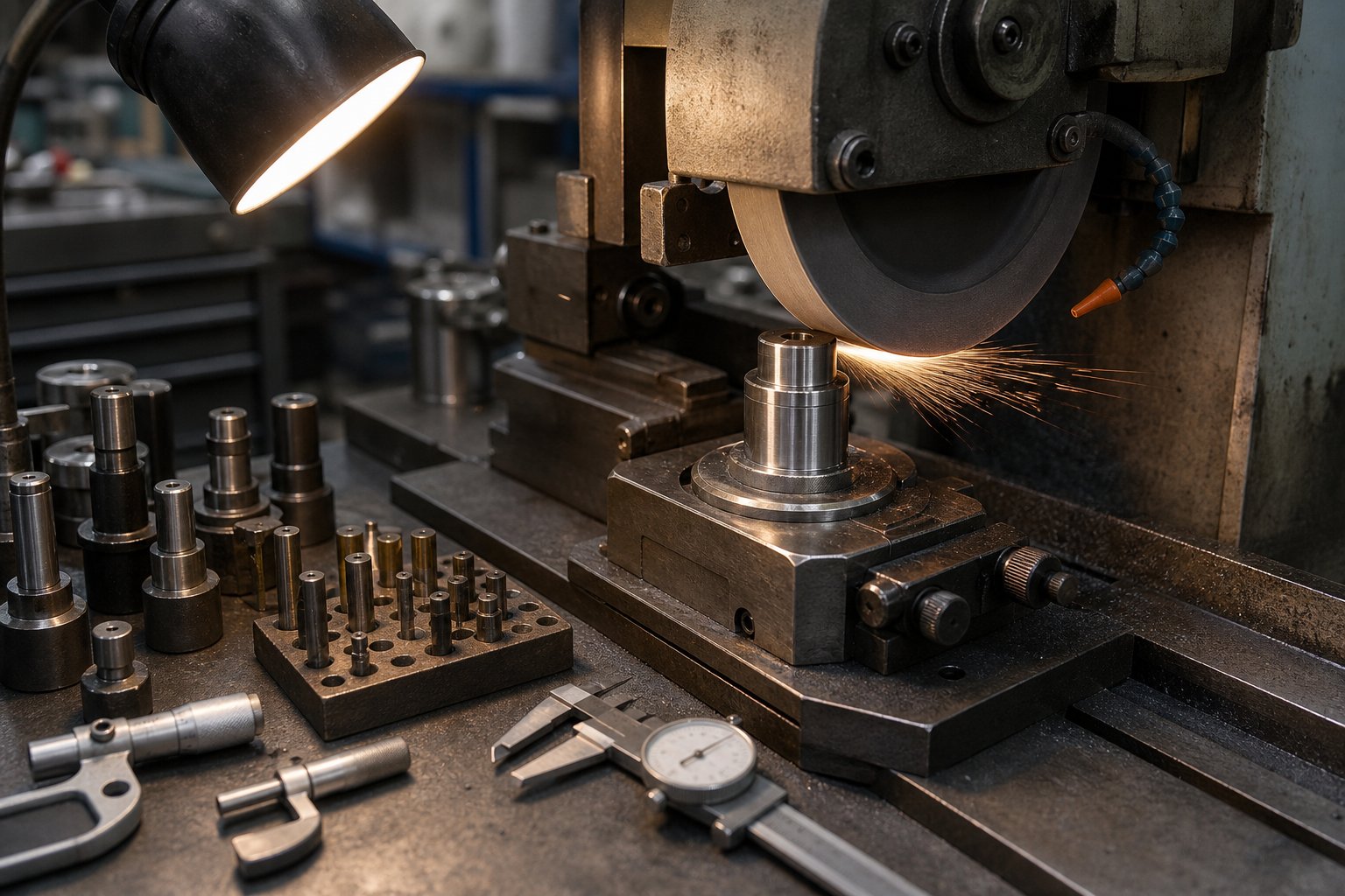
- Burr height increase - The most reliable early warning. As tooling punches lose their edge sharpness, the shear zone degrades and burrs grow taller on cut edges. Most precision die stamping operations set a maximum allowable burr height (often 0.05-0.10 mm depending on the application) as the trigger for sharpening.
- Dimensional drift - Hole positions, bend angles, or profile dimensions gradually shift out of tolerance as punch-to-die clearances open up from wear.
- Surface finish changes - Cut edges transition from clean and shiny to rough and torn. Formed surfaces develop scratching or galling marks.
- Increased stripping force - Worn edges create more friction, which makes stripping resistance climb. Operators may notice the press sounding different or the strip feeding less smoothly.
When should you sharpen? Waiting until defects appear on finished parts means wear has already progressed too far. As precision stamping manufacturers report, the most effective programs establish sharpening intervals based on actual stroke count rather than visual inspection alone. A typical schedule might call for grinding every 100,000 to 250,000 strokes depending on the material being stamped, with stainless steel and HSLA grades demanding more frequent service than soft copper or brass.
Each sharpening removes a small amount of material from the punch face and die insert surface, typically 0.05-0.10 mm per grind. Dies are designed with a total sharpening allowance built in, so tracking cumulative material removal is essential for predicting when components need full replacement rather than another grind.
Common Failure Modes and Prevention
Beyond gradual wear, progressive dies face several failure modes that can halt production instantly if left unchecked:
- Punch breakage - Small-diameter tooling punches are especially vulnerable. Lateral loading from strip misalignment, inadequate backing support, or hitting a double-thickness (strip fold-over) can snap a punch instantly. Guided stripper plates and proper pilot registration reduce lateral forces on narrow punches.
- Slug pulling - When a cut slug adheres to the punch face and pulls back up into the die, it can jam between the punch and stripper or embed itself in the next part. Common countermeasures include spring-loaded ejector pins, air vents drilled through piercing punches, vacuum relief structures, and reverse-tapered die buttons that hold slugs in compression.
- Misfeeds - The strip advances too far, too short, or at an angle. Worn pilot pins, inconsistent feeder release timing, or degraded strip guides all contribute. In high-speed precision die and stamping operations, even a 0.1 mm feed error compounds across stations and produces scrap.
- Timing issues - Cam-driven operations, nitrogen springs losing pressure, or press brake engagement drift can shift the die's internal timing. Operations that should complete at specific crankshaft angles begin executing early or late, causing interference between moving components.
These failures are interconnected. Punch wear increases burr height. Taller burrs raise stripping resistance. Higher stripping forces cause slugs to adhere to the punch. Slug pulling damages adjacent stations. One neglected wear zone cascades into multiple failure modes simultaneously.
Quality control in precision die stamping operations relies on catching problems before they reach this cascade point. Modern die protection systems use in-die sensors to monitor critical conditions in real time:
- Tonnage monitoring - Load cells detect force changes that indicate punch dulling, material variation, or double-thickness conditions.
- Misfeed detection - Proximity sensors verify strip position at each stroke, stopping the press before a mislocated strip reaches the cutting stations.
- Part ejection sensing - Photoelectric sensors confirm that finished parts have cleared the die before the next stroke executes.
- Stripper position monitoring - Sensors under spring strippers detect pulled slugs by identifying abnormal stripper travel.
Beyond in-die sensing, SPC dimensional monitoring, optical comparator checks, and inline vision inspection help track gradual drift and validate that parts remain within specification throughout a production run.
Expected die lifespan depends on the material being stamped, the steel grade of the die components, surface coatings, and maintenance discipline. Standard D2 steel stamping dies running mild steel might deliver 1 to 3 million strokes between major rework cycles. Carbide-inserted dies stamping soft materials can exceed 10 million strokes. High-speed stainless steel applications typically require major maintenance at shorter intervals, sometimes 500,000 to 1 million strokes, because the abrasive material accelerates edge breakdown.
A structured stamping die maintenance program ties all of these elements together into a predictable schedule:
- Per-shift inspection - Check part quality visually, verify burr height on sample parts, inspect for slug buildup, listen for abnormal press sounds, confirm lubrication flow.
- Scheduled sharpening triggers - Grind cutting stations at predetermined stroke counts. Log material removed per sharpening. Replace components when cumulative removal reaches design allowance.
- Monthly service - Inspect guide posts and bushings for wear. Check spring pressures (nitrogen cylinders lose charge over time). Verify pilot pin diameter and condition. Clean scrap evacuation channels.
- Annual overhaul - Full teardown, dimensional inspection of all critical components, replacement of worn guides and springs, re-qualification of die clearances, and fresh tryout samples to re-validate part quality.
Proper maintenance directly correlates with part quality consistency and total cost of ownership. A die that gets sharpened on schedule and inspected regularly maintains its original dimensional capability far longer than one that runs until failure forces a reaction. The discipline of preventive care is what transforms a high-cost precision tool into a reliable, long-term production asset, and understanding that asset's maintenance needs is just as important as knowing how to source the right one in the first place.
Sourcing the Right Progressive Die for High-Volume Production
Knowing how a progressive die works, what it costs, and how to maintain it only matters if the tool you receive actually performs as intended. The sourcing decision, choosing which progressive die manufacturers to partner with, locks in your production quality, lead time risk, and total cost of ownership for years. A poorly built die does not just produce bad parts. It bleeds money through unplanned downtime, excessive maintenance, and scrap rates that erode every efficiency gain the tool was supposed to deliver.
So how do you separate a capable progressive tool and die supplier from one that will cost you more in the long run?
What to Evaluate in a Progressive Die Supplier
Production engineers and procurement teams should assess potential progressive die stamping services providers across several criteria that go far beyond quoted price. As industry sourcing guides emphasize, the implications of choosing the wrong supplier go much deeper than the initial investment, affecting part quality, production efficiency, and long-term continuity.
- Engineering capability - Can the supplier optimize your strip layout, minimize station count without sacrificing quality, and propose design improvements? A strong progressive stamping company will challenge your assumptions constructively, not just build what you hand them. Look for in-house simulation tools like FEA and forming analysis software that catch problems before steel is cut.
- Build quality and materials - Ask what tool steel grades they use for punches and die inserts, whether they offer carbide options for high-wear stations, and what heat treatment processes they follow. These details determine whether the die lasts 500,000 strokes or 5 million.
- Tryout process thoroughness - Experienced die builders run multiple tryout iterations (T1 through T3), measure sample parts against print tolerances, and refine the tool until it consistently produces conforming parts at production speed. Ask how many sample rounds are included and what measurement methods they use for validation.
- Communication during development - The best progressive die metal stamping services providers maintain multiple touchpoints through the design and build phases. Strip layout approval, component review, and tryout reporting should all involve the customer. As one journeyman die maker puts it, consistent collaboration is essential to building a quality die and meeting expectations.
- Post-delivery support - Does the supplier offer maintenance guidance, sharpening recommendations, spare component supply, and troubleshooting support after the die ships? A progressive tool and die partner that disappears after delivery leaves you handling wear issues alone.
- Scalability and flexibility - Your volumes may grow or your part design may evolve. Evaluate whether the supplier can modify existing tooling, add stations, or build follow-on dies that integrate with your current production setup.
Matching Die Capabilities to Production Requirements
High-volume applications demand more from a supplier than just machining skill. You need a partner with direct experience running tight repeatability requirements across millions of cycles, not a shop that primarily builds prototype or low-volume tooling and occasionally takes on a production die.
When evaluating progressive die manufacturers for high-volume work, look for evidence of:
- Multi-station forming expertise, particularly for parts requiring 8 or more stations with combined cutting and forming operations.
- Experience with your specific material type and thickness range, since die clearances, coatings, and station design vary significantly across material families.
- In-house tryout presses that match or approximate your production press tonnage and speed, ensuring the die validates under realistic conditions.
- Quality systems and dimensional reporting that align with your internal standards, whether that means PPAP documentation, Cpk studies, or custom inspection protocols.
For teams sourcing progressive stamping dies oriented toward efficient multi-station forming and scalable mass production, suppliers like YICHEN specialize in high-volume progressive die engineering with an emphasis on tight repeatability and multi-station capability. Their progressive stamping die page provides a useful reference point when comparing supplier portfolios and production focus areas.
Ultimately, the right sourcing decision balances engineering depth, build quality, communication transparency, and long-term support. Price matters, but only in context. A die that costs 15% less upfront but requires rework after 200,000 strokes is far more expensive than one built to run reliably for millions of cycles. Treat your progressive die supplier as a production partner, not a vendor filling a purchase order, and the tooling will deliver returns for years.
Frequently Asked Questions About Progressive Stamping Dies
1. What is the difference between a progressive die and progressive die stamping?
A progressive die is the physical tooling itself, a precision-engineered block of hardened steel containing punches, cavities, and forming features designed for a specific part. Progressive die stamping is the manufacturing process that uses this tool inside a stamping press to produce parts at high volume. The distinction matters when evaluating tooling costs versus production costs, as they carry different timelines, budgets, and engineering decisions. Suppliers like YICHEN engineer both the tooling and the production process for high-volume applications requiring tight repeatability.
2. How many parts per minute can a progressive stamping die produce?
Progressive stamping dies typically produce one finished part per press stroke, with presses running anywhere from 25 to over 200 strokes per minute depending on part complexity, material thickness, and forming requirements. Simpler parts from soft materials like brass or copper can run at the higher end of this range, while complex parts requiring deep draws or multiple forming operations in stainless steel or HSLA grades run slower. This speed advantage over transfer dies (15-40 SPM) and single-stage operations makes progressive dies ideal for annual volumes exceeding 100,000 pieces.
3. How long does a progressive stamping die last before it needs replacement?
Die lifespan varies significantly based on the material being stamped, tool steel grade, surface coatings, and maintenance discipline. Standard D2 steel dies running mild steel typically deliver 1 to 3 million strokes between major rework cycles. Carbide-inserted dies stamping soft materials like copper or brass can exceed 10 million strokes. High-abrasion applications such as stainless steel may require major service at 500,000 to 1 million strokes. Consistent preventive maintenance including scheduled sharpening, spring pressure checks, and guide post inspection extends productive life substantially.
4. What materials can be used in progressive die stamping?
The most common materials include low-carbon steel (best formability, lowest cost), stainless steel (corrosion resistance but higher forming forces), aluminum alloys (lightweight but requires anti-galling coatings), copper (excellent conductivity, needs coated punches), brass (forgiving formability, minimal special requirements), and high-strength low-alloy steel (automotive structural use, demands carbide inserts). Strip thickness typically ranges from 0.1 mm for electronics connectors up to 6 mm for heavy brackets, with the optimal range for high-speed stamping between 0.3 mm and 3.0 mm.
5. How much does a progressive stamping die cost and what drives the price?
Progressive die costs range from approximately $15,000 for simple bracket tools to over $100,000 for complex multi-station dies with tight tolerances and carbide inserts. The primary cost drivers are number of stations (more stations means more machined components), part complexity and tolerance requirements (tighter specs require more tryout iterations), die material grade (carbide vs standard tool steel), production volume expectations (higher volumes justify more robust construction), and delivery timeline compression. However, when amortized over production volume, per-part tooling cost drops dramatically, often below $0.03 per piece at volumes of 2 million parts annually.


