
Progressive Stamping Die Design: Where Most Engineers Get Stuck
What Is Progressive Stamping Die Design
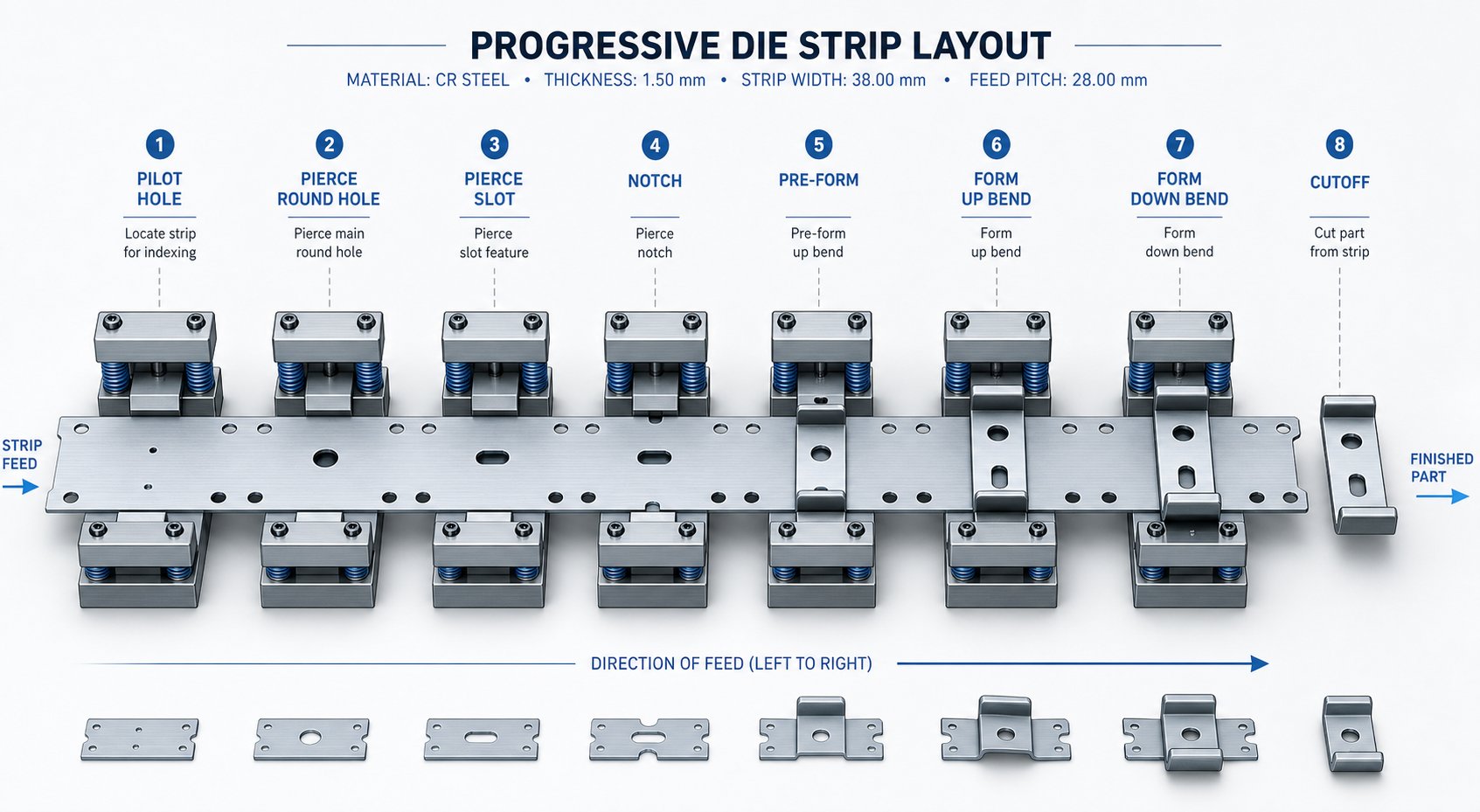
So what is a progressive die, exactly? A progressive die is a single tool containing multiple stations arranged in sequence, each performing a specific forming operation-piercing, blanking, bending, coining, or trimming-on a metal strip as it advances one pitch length per press stroke. The strip feeds from a coil, moves through the stations, and a finished part exits at the final station. Progressive stamping die design is the engineering discipline focused on planning this station sequence, strip layout, and tooling geometry so every operation builds on the last without removing the workpiece from the strip until cutoff.
Imagine a part that needs six holes punched, two bends formed, and an outer profile trimmed. Rather than handling that part across separate machines, a progressive die handles all of it in one continuous press cycle. The strip acts as both raw material and part carrier, which eliminates manual transfers and keeps cycle times short.
Defining Progressive Stamping Die Design
At its core, progressive die design solves a sequencing problem: how do you break a finished part into discrete forming steps, arrange those steps across stations, and keep the strip stable throughout? Each station does one job-or a small group of related jobs-while the strip indexes forward. The workpiece stays connected to the carrier until the very last station separates it. This approach allows progressive die stamping to produce complex geometries at speeds that single-operation tooling simply cannot match.
How Progressive Dies Differ from Compound and Transfer Dies
Engineers often weigh three die types when planning a stamping program. The differences come down to how the workpiece moves through the process and what level of complexity each method supports.
| Criteria | Progressive Die | Compound Die | Transfer Die |
|---|---|---|---|
| Operations per stroke | One operation per station, multiple stations per stroke | Multiple operations in a single stroke at one station | One operation per station, part transferred mechanically |
| Part complexity | Moderate to high (piercing, bending, forming, drawing) | Low to moderate (flat parts, single-plane cuts) | High (deep draws, large forms, complex 3D shapes) |
| Production speed | High-continuous coil feed, minimal handling | Moderate-single stroke but slower ejection on larger parts | Moderate-mechanical transfer adds cycle time |
| Typical volume suitability | Medium to very high volume | Low to medium volume | Medium to high volume |
Compound die stamping performs all cutting operations simultaneously in one press stroke, making it efficient for simpler flat parts like washers or electrical laminations. Transfer dies, on the other hand, separate the blank from the strip early and move it between independent stations using mechanical fingers-a better fit when deep drawing or large part size makes strip carry impractical.
Why Progressive Die Design Matters for High-Volume Production
The economic case for progressive die tooling is straightforward: you trade higher upfront tool cost for dramatically lower per-part cost at scale. Because multiple operations happen within a single die set, you eliminate part handling between machines, reduce labor, and minimize work-in-process inventory. Repeatability stays tight since every part follows the identical station sequence under controlled press conditions.
For production engineers targeting annual volumes in the hundreds of thousands or millions, progressive die stamping often represents the lowest total cost path-especially when the part design is stable and secondary operations can be engineered out of the process entirely.
That cost advantage, though, only materializes when the part geometry actually suits the process. Not every shape can ride a strip through ten stations without losing stability-and that evaluation is where most design projects either gain momentum or stall out.
Part Geometry Analysis and DFM Feasibility
Every stamping die design project starts with a part print-and the geometry on that print tells you whether a progressive approach will fly or fail. Engineers don't just look at the shape and guess. They apply a systematic set of Design for Manufacturability criteria to determine if the part can stay on a strip, form correctly across stations, and hold tolerances without requiring costly secondary work.
Evaluating Part Geometry for Progressive Die Suitability
When you first evaluate a print for progressive die suitability, you're asking a handful of critical questions. Can the part remain attached to a carrier strip through all forming stages without losing stability? Is there enough material between features to maintain structural integrity in the die sections? Do the tolerances require anything beyond what in-die operations can achieve?
Specific DFM criteria guide that evaluation. Hole diameters should be at least one times material thickness, and holes should sit a minimum of two times material thickness from any edge or formed feature to prevent distortion. Internal bend radii need to equal or exceed material thickness to avoid cracking. Symmetry matters because balanced parts track more predictably through the strip. Draw depth-to-diameter ratios determine whether a form can happen in a single station or needs to be staged. And grain direction orientation relative to bend axes directly affects fracture risk-bends perpendicular to rolling direction perform best.
How Feature Complexity Drives Station Count
Here's where metal stamping die design gets interesting. Every distinct feature on your part-each hole, bend, form, notch, or cutoff-potentially requires its own station. But it's not a simple one-to-one relationship.
Close-proximity holes, for example, can't always be punched in the same station. If two holes sit too near each other, punching both simultaneously weakens the die section between them and risks slug pulling or punch deflection. Separating them across two stations solves the structural problem. Similarly, a bend adjacent to a pierced hole needs sequencing care: you pierce first, then bend in a later station, because bending near a freshly punched hole distorts the hole geometry.
For complex parts, experienced engineers often design in one or two blind stations-empty positions reserved for future modifications if the part doesn't stamp dimensionally correct during tryout. This is a practical safeguard that avoids expensive rework of a completed stamping die.
Feasibility Red Flags and Design Modifications
Not every part belongs in a progressive stamping die. Certain geometry characteristics signal trouble early, and catching them before committing to a design saves significant time and cost. Watch for these common red flags:
- Deep draws exceeding material formability limits-when draw depth-to-diameter ratios push past what single or staged stations can achieve, a transfer die often becomes the more stable choice
- Extremely tight tolerances that exceed in-die capability, forcing secondary grinding, machining, or inspection operations that negate the speed advantage
- Asymmetric features creating unbalanced lateral forces on the strip, leading to strip wander and progressive misregistration across stations
- Thick materials limiting station density-heavier gauge stock demands larger punch-to-die clearances, bigger die sections, and more tonnage, which physically spreads stations apart and increases die length
- Large part size relative to strip width, making carrier retention unstable through multiple forming stages
When you spot these issues, the right move isn't always to abandon the progressive concept. Often, recommending part design modifications-adding a relief notch, relaxing a non-critical tolerance, adjusting a feature location by half a millimeter-transforms a borderline part into one that's fully progressive-die friendly. The best stamping programs treat DFM as a collaborative loop between part designer and die engineer rather than a one-way handoff.
Of course, confirming feasibility is only the first milestone. The real engineering challenge begins when you translate that geometry into a strip layout-deciding exactly how the material flows, where each operation lands, and how the stations sequence together to form a complete part without distorting what came before.
Strip Layout Development and Station Sequencing
The strip layout is where a progressive die stamping process either comes together or falls apart. It's the master plan that defines how raw coil stock transforms into finished parts-station by station, stroke by stroke. Every decision about die size, press selection, material cost, and dimensional accuracy flows directly from this single document. Get it right, and you have a stable, high-speed production system. Get it wrong, and you'll chase problems through every downstream phase of the build.
Strip Layout Fundamentals and Material Utilization
Three numbers define a strip layout at the most basic level: strip width, pitch (the distance the strip advances per stroke), and material utilization percentage. Engineers determine strip width by adding the part's maximum dimension across the feed direction, plus carrier material on one or both sides, plus minimum bridge widths between the part edge and strip edge. A common rule sets minimum bridge thickness at 1.25 to 1.5 times material thickness-thin enough to conserve material, thick enough to prevent scrap from twisting and jamming the die.
Pitch is calculated similarly: part length in the feed direction plus the bridge between consecutive parts. The target for well-designed progressive die tooling is material utilization above 75%, meaning less than a quarter of the coil becomes scrap. Achieving that target often means evaluating angular nesting, multi-row layouts, or flipping the part orientation on the strip to close gaps between blanked profiles.
Grain direction adds another constraint. Metal strip has a rolling direction, and bends oriented parallel to the grain are more prone to cracking. Wherever possible, the layout orients critical bend axes perpendicular to the grain direction. When a part has bends in multiple directions, you prioritize the most severe bend or the tightest radius for favorable grain alignment.
Station Sequencing Logic and Operation Order
Why does the sequence of operations matter so much? Because forming metal in the wrong order distorts features completed in earlier stations. Imagine punching a precision hole and then bending the flange right next to it-the bend stretches the material and pulls that hole out of round. Sequence the operations correctly (pierce first, then bend downstream), and you avoid the distortion entirely.
A typical station sequence for a multi-feature part in progressive dies follows this logic:
- Pilot holes and carrier notches-establish registration and strip tracking from the first stroke
- Internal piercing-punch all holes and slots while the strip is still flat, before any forming distorts surrounding material
- Lance and form operations-partial cuts that create tabs or louvers, followed by initial bends
- Drawing operations-deeper forms that pull material, staged across multiple stations if depth requires it
- Final trim and cutoff-separate the finished part from the carrier as the very last operation
Cutoff is always last because the carrier strip must physically hold the part through every preceding station. Pilot holes come first because every subsequent station relies on pilots to register the strip accurately. This isn't arbitrary-it's the engineering logic that keeps positional tolerances tight across what might be eight, ten, or even twenty stations of stage tooling.
Balancing Forces Across the Strip
Here's a factor many engineers overlook during layout development: force balance. Every piercing punch, every forming station, and every blanking operation generates force at a specific location across the strip width. If those forces concentrate on one side, the press slide tips laterally-causing uneven wear, punch misalignment, and accelerated die degradation.
MetalForming Magazine describes this as the "tipping moment" problem: you calculate each station's force and multiply it by its distance from the press centerline. The sum of those moments should approach zero. When it doesn't, the die designer can shift the strip layout off-center relative to the press slide, or apply shear angles to select punches to stagger the force peaks and reduce imbalance.
Asymmetric parts make this especially challenging. A part with features clustered on one side naturally creates unbalanced cutting forces. Solutions include running two parts mirrored across the strip centerline (a double-row inverted layout), adding dummy stations with equalization punches on the light side, or strategically sequencing heavy-cut operations opposite each other. The goal is always the same: keep lateral forces balanced so the strip tracks straight and the die runs without premature wear.
With the strip layout locked-stations sequenced, material utilization optimized, forces balanced-the next critical variable is how the die interacts with the material itself. Different alloys demand fundamentally different clearances, pressures, and compensation strategies that reshape the tooling from the inside out.
Die Clearance and Material-Specific Design Adjustments
A perfectly sequenced strip layout means nothing if the punch-to-die clearance is wrong for the material you're cutting. Clearance-the gap between the punch's cutting edge and the die button's cutting edge, expressed as a percentage of stock thickness per side-controls edge quality, tool life, and even whether slugs stay in the die or vacuum-adhere back up to the retracting punch. Yet clearance isn't a single universal number. It shifts significantly based on the alloy sitting on the die surface.
Die Clearance Selection and Its Impact on Edge Quality
When a punch enters material, it doesn't slice cleanly like a knife. It initiates a fracture from both the punch edge and the die edge. Correct clearance ensures those fracture lines meet in the middle, producing a part edge with a clean shear band and minimal burr. Too tight, and you get secondary shearing-a double-cut appearance-along with dramatically higher punch forces and accelerated tool wear. Too loose, and excessive rollover and burr form on the part edge, plus the slug can tilt and pull back up with the punch.
The general industry rule starts at roughly 10% of material thickness per side, but research shows that increasing to 11-20% for certain materials significantly extends tooling life without meaningfully degrading edge quality. The real answer depends on material type and hardness. Here's what experienced metal stamping die engineers typically specify:
| Workpiece Material | Clearance Per Side (Soft/Annealed) | Clearance Per Side (Hard/Work-Hardened) |
|---|---|---|
| Aluminum | 10% | 20% |
| Brass / Copper | 6% | 15% |
| Mild Steel (Low-Carbon) | 10% | 12% |
| Stainless Steel | 15% | 20% |
| High-Strength Steel (HSLA/AHSS) | 18% | 20%+ |
Notice the range. Aluminum progressive stamping applications can get away with tighter clearances in the soft temper because aluminum fractures cleanly under lower shear stress. Brass progressive stamping and progressive stamping copper parts use the tightest clearances of any common material-as low as 6% per side in annealed conditions-because copper alloys shear with minimal fracture propagation and produce excellent edge finish. Carbon steel progressive stamping sits in the middle ground, while stainless and high-strength grades push toward the wide end of the spectrum to manage their higher cutting resistance.
One overlooked consequence of clearance selection: slug retention. Tighter clearance creates a slug that fits snugly in the die button, which actually helps hold it in place. Open up the clearance, and slugs sit looser in the pocket, increasing the risk they'll ride back up on the punch face. Designers counter this with slug retention features-angular relief in the die button walls or vacuum channels beneath the cutting surface.
Designing for Stainless Steel and High-Strength Alloys
Stainless steel progressive stamping presents a distinct set of engineering challenges that ripple through every aspect of the die. The material work-hardens rapidly during forming, meaning each successive hit slightly increases the strength of the zone around the deformed area. Punch forces run 40-60% higher than equivalent-thickness mild steel. Tool wear accelerates-particularly on piercing punches that contact the work-hardened edge zone repeatedly.
Design countermeasures for progressive metal stamping in stainless and AHSS grades include:
- Increased die clearance (15-20%+ per side) to reduce cutting force and delay galling
- Heavier stripper spring pressure to ensure positive strip control against the increased stripping force from work-hardened material gripping the punch
- Carbide or PM tool steel inserts for punches and die buttons in high-wear stations, replacing conventional D2 where production volumes justify the cost
- Surface coatings (TiN, TiCN, or AlCrN) on punches to reduce adhesive wear and galling in stainless applications
- Reduced station density-spacing stations farther apart to accommodate larger die sections and heavier backup plates needed to resist higher cutting forces
The net effect? A progressive die designed for 304 stainless steel will be physically larger, require more tonnage, and demand more frequent maintenance than one built for the same part geometry in mild steel. These aren't minor adjustments-they fundamentally reshape the die.
Springback Compensation Strategies by Material
Every metal bends a little further than where it stays. When the punch retracts, the workpiece springs back toward its original flat state by an amount determined by the ratio of yield strength to elastic modulus. High-strength materials spring back more because they have higher yield strength relative to their stiffness. Aluminum springs back less in absolute terms but is trickier because its lower modulus means the elastic recovery percentage can be unpredictable across alloy tempers.
Engineers compensate using three primary strategies:
- Overbending-designing the punch geometry to bend past the target angle so the part relaxes back to nominal. A part requiring a 90-degree bend in high-strength steel might need a punch ground to 87 or 85 degrees, depending on the alloy's measured springback.
- Bottoming (coining the bend zone)-applying enough tonnage to plastically deform the material through its full thickness at the bend apex, which eliminates the elastic recovery layer. This works well for carbon steel progressive stamping but requires significantly more press force.
- Step bending across multiple stations-taking a 90-degree bend in two or three increments, with each stage slightly overbent. This distributes the forming strain and produces more predictable results in materials with high work-hardening rates.
For mild steel and brass, empirical compensation rules accumulated over decades of shop-floor experience generally produce accurate results. You overbend 1-3 degrees and you're close. But for stainless steel, AHSS grades, and high-strength aluminum alloys, those rules break down. Springback becomes nonlinear and sensitive to material lot variation. This is where forming simulation software earns its keep-FEA-based models that predict springback based on actual stress-strain curves rather than handbook approximations.
The practical takeaway: material selection doesn't just change what alloy you order from the service center. It reshapes clearances, press tonnage, tool materials, bend compensation, and maintenance intervals throughout the entire die. And that material influence extends beyond the cutting and forming inserts-it directly affects how the strip is carried, guided, and registered from station to station.
Carrier Design and Pilot Placement Strategy
Strip carriers and pilot pins rarely get the attention they deserve in progressive die discussions-yet these two elements determine whether a stamping die set produces parts within tolerance or generates scrap by the boxful. The carrier holds the part through every forming stage. The pilots position it with micron-level accuracy at each station. Together, they form the invisible infrastructure that makes progressive stamping dies function as precision instruments rather than blunt force tools.
Strip Carrier Types and Selection Criteria
The carrier is the portion of strip material that connects each developing part to the coil as it moves through the die. It's sacrificial-discarded as scrap after cutoff-but its design governs strip stability, material utilization, and forming freedom at every station. Three primary configurations cover the majority of progressive stamping tool applications:
A center carrier runs a web of material down the middle of the strip, with part features formed on both sides. A single-side carrier attaches the part to material on one edge of the strip, leaving the other three sides accessible for cutting and forming. A dual (double-side) carrier retains material on both strip edges, suspending the part between them.
Each type suits different part geometries and process demands. The choice depends on what the part looks like, how much forming it requires, and how forces distribute across the strip width.
| Criteria | Center Carrier | Single-Side Carrier | Dual (Double-Side) Carrier |
|---|---|---|---|
| Material utilization | Moderate-center web adds width | High-minimal scrap on open side | Lower-material reserved on both edges |
| Strip stability | Good for symmetric parts | Lower-unbalanced attachment creates lateral pull | Excellent-balanced support resists twist and camber |
| Suitability for asymmetric parts | Limited-works best with mirrored or symmetric geometry | Good-part hangs freely from one side | Excellent-balanced grip compensates for asymmetric forces |
| Typical applications | Symmetric flat parts, electrical contacts, simple brackets | Small connectors, terminals, parts with forming on three sides | Large parts, deep-drawn shells, heavy forming, wide blanks |
How do you choose? Start with part geometry and cutoff requirements. Symmetric parts with moderate forming often pair naturally with center carriers-the web provides balanced support and simplifies strip tracking. But when a part requires deep forming or drawing, a stretch web carrier configuration becomes necessary to allow metal to flow freely without upsetting the pitch distance between successive parts. Dual carriers excel here because they anchor both sides of the strip, preventing the severe camber and twist that heavy one-sided forming would otherwise introduce.
Single-side carriers maximize material access but come with a tradeoff: the asymmetric attachment generates unequal stripping forces that can pull the strip sideways. In a sheet metal stamping die running at 200+ strokes per minute, even slight lateral drift compounds rapidly. Engineers using single-side carriers typically add secondary guide rails or stabilizing features to counteract this tendency.
Carrier strength matters too. The web must withstand feeding force across all stations without buckling or tearing-roughly 10% of the total strip weight multiplied by the number of progressions, according to stamping die design authorities. No universal formula exists for carrier dimensioning, so experienced designers rely on material type, thickness, and the severity of forming operations to set web width and geometry.
Pilot Pin Placement Strategy for Station Accuracy
Pilots are ground steel pins mounted in the upper die that descend into pre-punched holes in the strip before any other tooling engages the material. Their job is simple but critical: force the strip into exact X-Y position before punching or forming begins. Without them, feed-roll inaccuracy would accumulate from station to station until positional errors exceeded part tolerances.
Think of it this way-the feeder provides coarse positioning, advancing the strip to an approximate location. The pilots then perform fine correction, physically pushing the strip into its true theoretical position with each press stroke. This "coarse-then-fine" cycle resets positional error at every station, which is how progressive stamping dies maintain tolerances of +/-0.05 mm or better across ten or more sequential operations.
Effective pilot placement follows several engineering rules:
- Frequency: Place pilots in every station for maximum accuracy. On longer dies where cost is a concern, every other station is acceptable for non-critical intermediate operations-but all forming and final trim stations need dedicated pilots.
- Spacing: Position pilot pins as far apart across the strip width as geometry allows. Wider spacing provides greater angular control, preventing strip rotation (yaw) that close-spaced pilots cannot detect or correct.
- Upstream of forming: Pilots must engage the strip before any forming tools contact the material. Forming operations can distort pilot holes if they occur too close, so locate critical pilots upstream (in the feed direction) of heavy bends, draws, or embosses that could deform the registration holes.
- Engagement sequence: The pilot tip enters the strip first, followed by the locating diameter. Feed rolls must release the strip before the pilot's locating diameter engages-otherwise the feeder fights the pilot, bending the pin, elongating the hole, and degrading accuracy over time.
Pilot sizing is equally important. Clearance between the pilot diameter and the pilot hole typically runs 0.0005 to 0.001 inches, depending on material thickness and strip rigidity. Tighter clearance improves positional accuracy but increases the risk of binding if the strip isn't perfectly flat. Thicker materials tolerate tighter pilot fits because the strip resists deformation; thinner foils need slightly more clearance to avoid dimpling around the pilot hole during engagement.
Managing Tolerance Stack-Up Across Stations
Here's the fundamental challenge of any stamping die set with multiple stations: each operation introduces the potential for small positional deviations. A pierced hole in station 3 might sit 0.02 mm off nominal. A bend in station 7 adds another 0.01 mm shift. By station 12, those errors could stack-unless the die's registration system actively breaks the chain.
Pilots accomplish this by resetting the strip to absolute position at every engagement point. The cumulative error from feed-roll mechanical play, thermal expansion of the strip, and elastic springback after forming gets zeroed out each time the pilot pin seats. This is why progressive dies can hold feature-to-feature tolerances of +/-0.05 to +/-0.10 mm even across parts requiring fifteen or more stations-the error never gets the chance to compound beyond a single pitch increment.
Several factors determine how tight those achievable tolerances actually get:
- Pilot-to-hole clearance: Every thousandth of an inch of clearance between pilot and hole represents potential strip displacement. A 0.001-inch clearance means the strip could sit anywhere within a 0.001-inch diameter zone at that station. Features formed in that station inherit that uncertainty.
- Distance from pilot to feature: The farther a formed feature sits from the nearest pilot, the more angular error amplifies positional deviation. A feature 50 mm from the pilot with a 0.01-degree strip rotation error displaces roughly 0.009 mm-small, but meaningful when tolerances are tight.
- Strip thickness and rigidity: Thicker strips resist deflection between pilot points, maintaining straightness across the die width. Thin foil stock can bow or ripple between supports, allowing mid-span features to shift relative to the piloted edges.
- Thermal effects at speed: High-speed progressive die stamping generates frictional heat that expands the strip incrementally between stations. On long dies running at 400+ strokes per minute, thermal growth of even a few microns per pitch adds measurable positional drift-something pilot correction handles automatically but that designers must account for in pilot hole sizing.
The practical design guideline: if two features on the same part must hold a tight positional relationship, form them in the same station or in adjacent stations sharing the same pilot pair. Spreading tightly toleranced features across distant stations multiplies the variables that can introduce error-even with pilots correcting at every step.
Carrier design and piloting strategy together form the backbone of strip control. But once those stamping die components are defined, a different question emerges: does the press have enough capacity to drive all these stations simultaneously? Calculating the total force demand across a fully loaded progressive die-and matching it to the right press-is the next engineering hurdle that separates a buildable concept from a production-ready tool.
Tonnage Calculations and Press Selection
You can have a flawless strip layout, perfect clearances, and ideal pilot placement-but if the progressive stamping press can't deliver enough force to drive all those stations simultaneously, none of it matters. Tonnage calculation is where the die design meets physical reality, and underestimating it is one of the fastest paths to press jams, broken punches, and stalled production.
Calculating Cutting and Forming Forces Per Station
Every station in a progressive die demands force independently. A piercing station needs enough tonnage to shear its holes. A bending station needs force to plastically deform the material. A drawing station needs force to stretch the shell walls. You calculate each one separately using formulas matched to the operation type.
For blanking and piercing-any operation that shears material-the fundamental formula is straightforward:
Cutting Force (tons) = Perimeter of cut (in.) x Material Thickness (in.) x Shear Strength (tons/in²)
For a 2-inch diameter hole in 0.060-inch mild steel (shear strength ~25 tons/in²), that's: (2 x 3.1416) x 0.060 x 25 = 9.4 tons. Multiply that logic across every pierced feature in the station, and you have the station's cutting load.
Forming operations use a different property. Drawing and bending put material under tension rather than shear, so the calculation substitutes Ultimate Tensile Strength (UTS) for shear strength. A bending station's force depends on bend length, material thickness, die opening width, and the material's tensile properties. Each station gets its own calculation-no shortcuts, no averaging.
Total Press Tonnage and Safety Factors
Here's the detail many engineers miss: total required tonnage for a progressive die press is the sum of all station forces occurring in a single press stroke-not just the heaviest station. Every punch, every form, every spring, and every pad exerts force simultaneously at bottom dead center. You must account for all of them:
- Piercing forces-all holes, slots, and notches punched in that stroke
- Blanking forces-carrier notches, trim operations, and final cutoff
- Bending forces-all forming stations engaged during the stroke
- Drawing forces-cup or shell forming plus blank holder pad pressure
- Coining forces-localized high-pressure stations for embossing or dimensioning
- Stripper spring pressure-the cumulative force of all stripper springs and nitrogen cylinders compressing during the stroke
- Lifter pin pressure-spring-loaded pins that elevate the strip between strokes
- Driven cam forces-any side-action mechanisms engaging during the stroke cycle
Sum everything, then add a safety factor of 20-30% above the calculated total. This margin covers material property variation between coil lots, progressive punch dulling between sharpening cycles, and the dynamic snap-through force that occurs during blanking. Snap-through-the sudden release of energy when the punch fractures through the material-creates impulse loading that exceeds the static cutting force momentarily. A press sized too close to the theoretical minimum will feel this as a jarring shock at the bottom of every stroke, accelerating bearing wear and reducing die life.
Press Selection Criteria Beyond Tonnage
Tonnage capacity alone doesn't qualify a progressive stamping machine for the job. Several mechanical parameters must also align with the die's physical requirements:
- Bed size: The press bed must accommodate the die footprint with room for clamping. A die stamping press rated at adequate tonnage but with an undersized bed concentrates load over a smaller area, causing localized deflection that degrades part quality.
- Shut height: The distance between the slide face and the bed surface at bottom dead center must exceed the die's closed height. Set shut height too tight during setup and you risk crushing the die; too loose and forming stations won't reach full bottom.
- Stroke length: Must be sufficient for the deepest draw or highest form in the die, plus clearance for strip lifters to elevate the material for feeding.
- Speed rating: High-volume progressive die operations run at 200 to 600+ strokes per minute. The progressive die press must be rated for continuous cycling at those speeds without thermal buildup in the bearings, clutch, or brake. A press designed for intermittent duty will overheat and lose dimensional stability under sustained high-speed production.
Energy is the often-overlooked companion to tonnage. A press might have enough peak force but insufficient flywheel energy to sustain that force through the working portion of the stroke-especially for drawing operations that engage material high in the stroke cycle. Insufficient energy is a common cause of press jams at bottom dead center, where the flywheel decelerates below the speed needed to complete the work. Always validate both tonnage and available energy at your target strokes per minute.
Press selection locks in the production envelope-speed, force, and physical workspace. But within that envelope, it's the die components themselves that determine how long the tool runs between maintenance stops. The materials chosen for punches, die buttons, and wear plates dictate whether you're sharpening every 50,000 hits or running past a million.
Die Material Selection and Maintenance Planning
A progressive tool and die is only as durable as the materials inside it. You can optimize every station sequence and nail every clearance calculation, but if the punches and die buttons are built from the wrong steel grade, you'll be pulling the die for sharpening far too often-or worse, replacing cracked inserts mid-run. Stamping die steel selection is the decision that translates your design intent into actual production longevity, measured in hits between service intervals.
Tool Steel Grades for Progressive Die Components
Die tooling design involves matching each component's material to its dominant failure mode. Will the punch wear down gradually from abrasion? Will it chip under repeated impact? Will it deform under sustained compressive load? The answer determines which grade belongs in that station.
Here's the practical hierarchy, from general-purpose to extreme-duty:
| Tool Steel Grade | Working Hardness | Primary Strength | Best Application |
|---|---|---|---|
| A2 (1.2363 / SKD12) | 58-62 HRC | Balanced toughness and wear resistance | Moderate-volume general work where no single failure mode dominates |
| D2 (1.2379 / SKD11) | 58-60 HRC | High abrasive wear resistance | High-volume blanking and piercing where edge retention is critical |
| M2 (1.3343 / SKH51) | 60-65 HRC | Wear resistance with superior compressive strength | Punches under heavy load at elevated production speeds |
| M4 High-Speed Steel | 62-66 HRC | Maximum wear resistance in wrought steel | High-speed piercing of abrasive or coated materials |
| Carbide (Tungsten Carbide) | 88-92 HRA | Extreme hardness and wear life | Ultra-high-volume production or abrasive materials like silicon steel |
Think of it as a cost-versus-life tradeoff. A2 provides a balanced solution when wear, deformation, and impact all contribute to tool degradation without any single mechanism clearly dominating. It's a solid default for dies running moderate production volumes where multiple stations experience mixed loading conditions.
D2 steps in when production volume climbs and edge wear becomes the limiting factor. Its high chromium carbide content keeps cutting edges sharp over long runs-but once chipping or cracking appears, D2's lower toughness means it's time to switch to something more impact-resistant like S7, or step up to M2 where both wear and compressive load contribute to failure.
M2 and M4 high-speed steels occupy the upper tier for wrought stamping die steel applications. They maintain edge geometry under repeated compressive loading that would deform D2, making them ideal for punches in high-speed progressive dies running at 300+ strokes per minute. The tradeoff is machinability-these grades are harder to grind and require more careful heat treatment to achieve consistent results.
When Carbide Inserts Justify Their Cost
Progressive carbide stamping dies represent the top of the durability ladder-and the top of the price list. A carbide punch or die button can cost 5 to 10 times more than its D2 equivalent. So when does that investment make sense?
The economic crossover depends on three factors:
- Production volume: When annual volumes exceed 5-10 million hits, carbide's extended life between sharpenings (often 10x longer than tool steel) reduces total downtime cost enough to offset the higher upfront investment
- Workpiece material: Abrasive materials like silicon steel laminations, stainless steel, and coated strip stock accelerate tool steel wear dramatically. Carbide resists this abrasion far more effectively, maintaining edge condition where D2 would need resharpening every 50,000-100,000 hits
- Tolerance sensitivity: Parts with tight dimensional requirements benefit from carbide's dimensional stability-less wear means less drift between maintenance cycles, which means fewer out-of-tolerance parts during extended runs
One critical caveat: carbide is brittle. It resists wear beautifully but cracks under impact or lateral loading. As progressive die design experts note, "carbide is like concrete and will disintegrate before it wears." This means carbide works best in piercing and blanking stations with well-guided punches and minimal lateral force-not in forming stations where off-axis loads are common. Designers must ensure proper punch guidance length and eliminate any misalignment that could side-load the carbide insert.
Maintenance Intervals and Design for Serviceability
Stamping die maintenance isn't just about sharpening on a schedule-it's about how the die was designed to be serviced in the first place. A die that requires complete disassembly to replace one worn punch costs far more in downtime than one engineered for modular access.
Key design-for-serviceability principles include:
- Sectioned inserts: Breaking die buttons and cutting steels into individual segments rather than monolithic plates. When one cutting edge wears, you replace that insert alone-not the entire die section.
- Quick-change punch holders: Retention systems that allow individual punches to be removed and replaced without disturbing adjacent tooling. Ball-lock or wedge-lock holders make this a five-minute operation instead of an hour-long rebuild.
- Heel block design: Precision heel blocks and guide keys that force the upper and lower die halves into exact alignment during reassembly, eliminating the risk of human error causing punch-to-die misalignment after maintenance.
- Documented shim stacks: Maximum shimming limits noted on the die assembly drawings, preventing over-shimming that could cause punch interference with strippers or other components.
Experienced progressive die suppliers like YICHEN engineer this maintenance accessibility directly into their die designs from the concept phase-supporting long-run production with predictable service intervals and scalable maintenance planning for high-volume metal parts. When a die is designed so that the press operator or toolroom technician can swap wear components without specialized skills, you protect production uptime regardless of workforce variability.
The practical reality of stamping die maintenance is this: a die running one million strokes per year with D2 inserts might need sharpening every 150,000-250,000 hits. Upgrade critical stations to carbide, and that interval stretches to 1,000,000+ hits. But sharpening frequency is just one variable. The design must also account for how quickly you can get the die back into the press once it's pulled-and that speed comes from thoughtful modular construction, not from better steel alone.
Material selection and serviceability planning determine how long a die runs and how fast it recovers. But even the best materials can't compensate for design-phase oversights that create chronic failure patterns-misfeeds, slug pulling, punch breakage, and station misalignment problems that keep recurring no matter how many times you sharpen or replace components.
Common Design Failures and Root Cause Prevention
Most troubleshooting guides focus on what to do after a progressive die starts failing in production. That's backwards. The majority of chronic progressive die stampings problems-misfeeds, slug pulling, punch breakage, dimensional drift-can be traced back to decisions made during the design phase, long before the die ever sees a press. Fixing them after the tool is built means expensive rework, production delays, and compromised die life. Preventing them during design costs almost nothing.
If your die keeps misfiring on the same failure mode run after run, the root cause probably isn't wear or operator error. It's a design gap that no amount of sharpening or adjustment will eliminate.
Misfeed and Strip Progression Failures
A misfeed-where the strip fails to advance the correct pitch distance before the press cycles-is one of the most common production interruptions in tool and die stamping. When it happens, punches hit the wrong location, pilots engage off-center, and the resulting parts are scrap. Worse, a severe misfeed can crash punches into die buttons, causing thousands of dollars in tooling damage in a single stroke.
What causes misfeeds? Usually one of four design-phase oversights:
- Insufficient pilot engagement length: If pilot pins don't descend far enough into the strip before cutting or forming tools contact the material, the strip isn't fully registered when the operation begins. The fix is designing longer pilot tip engagement-typically 1.5x material thickness minimum-and verifying that feed release timing allows pilots to seat completely before other tooling engages.
- Excessive strip camber from asymmetric operations: When large amounts of material are removed from one side of the strip, internal coil stresses release unevenly, causing the carrier to bow laterally. Over thousands of cycles, this progressive camber pulls the strip against guides and pilots, creating feed resistance and eventual misfeed. Design countermeasures include adding balancing trim operations on the opposite side or switching to a dual carrier configuration that distributes stress symmetrically.
- Inadequate lifter height: Between press strokes, spring-loaded lifter pins raise the strip above the die surface so it can advance freely. If lifter height is too low, formed features or downward-bent tabs drag across the die face during feeding. The strip hesitates, the feeder overshoots its timing window, and the next stroke catches the strip out of position. Designers must calculate lifter height based on the deepest downward form in the die plus a clearance margin-not just material thickness.
- Feed length exceeding press feed accuracy: Longer pitch distances amplify the mechanical inaccuracy of servo or air feeders. A feeder rated at +/-0.05 mm accuracy produces twice the absolute error on a 50 mm pitch versus a 25 mm pitch. When the design demands long progression distances, shorter feeds with higher station counts often produce more stable results than fewer stations with aggressive pitch lengths.
Each of these problems is preventable with proper design attention. The common thread? They all stem from underestimating how the strip behaves dynamically at production speed-something that looks fine in CAD or during slow-speed tryout but degrades rapidly at 200+ strokes per minute.
Slug Pulling and Punch Breakage Prevention
Slug pulling is deceptively destructive. A single pulled slug-a punched-out disc of scrap that adheres to the retracting punch and re-enters the strip-can damage every downstream station in one press stroke. It dents part surfaces, cracks forming punches, and jams between cutting edges. In high speed progressive die stamping running at 300+ SPM, there's zero time for an operator to react before the damage cascades through the entire die.
Why do slugs pull? The primary cause is vacuum. When a punch shears through material, the slug cups slightly, trapping air between the concave slug face and the flat punch face. During withdrawal, this sealed pocket creates suction that lifts the slug out of the die button. Heavy lubricants increase the sealing effect, and larger cutting clearances produce slugs slightly smaller than the die opening-eliminating the interference fit that would otherwise retain them.
Design-phase countermeasures that prevent slug pulling before it starts:
- Slug retention geometry in die buttons: Machining small angular slots or barbs into the die button walls creates burrs on the slug's perimeter that wedge it in place. A reverse-taper die button-where the bore narrows slightly toward the exit-holds slugs in compression. Only 0.0005 to 0.001 inches of taper is needed; excessive taper can split the button.
- Air vent channels in punches: A small through-hole drilled down the center of the punch allows trapped air to escape during withdrawal, breaking the vacuum seal. This simple modification eliminates the suction mechanism entirely on larger punches.
- Proper clearance ratios: Tighter clearance produces slugs that press-fit into the die button, physically locking them in place. When die design requires larger clearances for edge quality or tool life reasons, slug retention features become mandatory rather than optional.
- Punch face modifications: Grinding a slight dome, cross-groove, or step onto the punch face disrupts the flat seal that creates vacuum. Spring-loaded ejector pins inside larger punches physically push slugs off the face during retraction.
Punch breakage has its own set of design-phase root causes. The most common: undersized punch cross-sections. A punch's resistance to stripping force depends on its cross-sectional area and length. Long, slender punches-those with a length-to-diameter ratio exceeding 8:1-are extremely vulnerable to buckling under the stripping load that occurs when the material grips the punch during withdrawal. Designing adequate punch guidance length (supported within the stripper plate) and keeping length-to-diameter ratios below critical thresholds prevents this failure mode entirely.
Lateral loading from misalignment is another punch killer. If the punch doesn't enter the die button perfectly concentrically, side forces develop that snap small-diameter punches or chip carbide inserts. The design fix is ensuring adequate guide pin engagement and stripper plate guidance bore precision-problems that are cheap to prevent but expensive to diagnose after the fact.
Station Misalignment and Cumulative Error
When progressive die stampings show gradual dimensional drift or inconsistent feature positions, the root cause is often station misalignment-a condition where the upper and lower die halves don't maintain perfect registration under load. This can be static (the die was built slightly off) or dynamic (the die deflects during each stroke and springs back, with the deflection pattern shifting as components wear).
Design-phase preventive measures that control misalignment:
- Adequate guide pin sizing and placement: Guide pins should be sized for the total lateral force they'll resist, not just fitted to standard catalog sizes. Place them as far apart as die geometry allows-wider spacing resists angular misalignment more effectively than larger pins placed close together.
- Proper die set rigidity: Shoe thickness must match the tonnage and span. Thin shoes flex under load, causing the outer stations to shift relative to center stations. A rule of thumb: minimum shoe thickness equals 1.5 times the longest unsupported span divided by 6-but FEA validation is more reliable than rules for complex dies.
- Thermal expansion allowances for high-speed operations: At 400+ strokes per minute, frictional heating expands die components differentially. Steel expands roughly 12 microns per meter per degree Celsius. A 600 mm long die running hot can grow 30-50 microns across its length-enough to shift outer station alignment outside tolerance. Designers accommodate this with slight clearance in non-critical locating features while maintaining rigid registration at critical datum points.
- Backup key positioning for repeatable die alignment: Precision ground keys between die sections and shoes force components into exact position during assembly. When a die is pulled for maintenance and reassembled, these keys eliminate the possibility of human error in realignment-every rebuild produces the same registration as the original assembly.
Modern progressive die design software enables FEA simulation of die deflection under full production load, predicting exactly where and how much the die structure will flex before a single block of steel is cut. This capability transforms misalignment from a tryout discovery into a design-phase calculation. Engineers can add stiffening ribs, increase shoe thickness in critical zones, or relocate guide pins to counteract predicted deflection-all in the CAD model, at zero material cost.
CAD/CAE validation workflows catch these issues early by simulating the entire press stroke: punch forces, stripper engagement, forming loads, and their combined effect on die structure. The progressive die design software flags stations where deflection exceeds user-defined thresholds, allowing designers to iterate before committing to tooling construction. This simulation-driven approach represents a fundamental shift from the traditional "build it, try it, fix it" cycle that costs weeks of tryout time and thousands in rework.
Preventing failures at the design stage is the most cost-effective quality strategy available. But even a perfectly designed die needs to be built by a supplier with the capability to execute that design at full precision-and maintained by a team that understands the engineering intent behind every feature. That connection between design quality and supplier capability is what ultimately determines whether a progressive die program delivers consistent parts over millions of cycles or degrades into a chronic maintenance problem.
Selecting a Progressive Die Partner for Mass Production
A progressive die is only as good as the shop that builds it. You can specify every clearance, sequence every station perfectly, and select ideal tool steels-but if the supplier lacks the precision equipment, material knowledge, or process discipline to execute that design at full fidelity, you'll spend months in tryout chasing problems that should never have existed. For production engineers and procurement teams sourcing progressive stamping dies, supplier selection isn't a purchasing decision. It's an engineering decision with direct consequences for part quality, production uptime, and total program cost.
What to Evaluate in a Progressive Die Supplier
Not all progressive die manufacturers operate at the same capability level, and a polished website doesn't guarantee precision on the shop floor. When you're evaluating potential partners for progressive die metal stamping services, focus on criteria that reveal actual technical depth rather than surface-level credentials:
- In-house design and simulation capability: Does the supplier run FEA-based forming simulation and strip layout optimization internally, or do they outsource design and simply machine to someone else's model? Shops that own the full design-to-build cycle catch problems faster and iterate more efficiently during tryout.
- Tool steel sourcing and heat treatment control: Ask where they source D2, M2, and carbide inserts, and whether heat treatment is performed in-house or subcontracted. Inconsistent heat treatment is a leading cause of premature punch failure-suppliers who control this process directly produce more reliable tooling.
- Tryout press availability: A dedicated tryout press allows the supplier to validate die performance under realistic conditions before shipping. Without one, you're accepting an unproven tool and absorbing all tryout risk at your facility.
- Experience with target material types: A supplier expert in mild steel stampings may struggle with stainless steel or high-strength alloys that demand different clearances, coatings, and force calculations. Ask for examples of dies they've built in your specific material and gauge range.
- ISO certification status: ISO 9001 certification indicates documented quality systems. For automotive programs, IATF 16949 compliance signals capability for PPAP-level documentation and process control.
- Communication responsiveness during design iterations: Progressive die programs involve multiple design reviews and engineering changes before steel cutting begins. A supplier that takes a week to respond to a DFM question will cost you months over a full program timeline.
These criteria separate precision die and stamping specialists from general job shops. A supplier strong across all six dimensions can take ownership of die performance rather than simply delivering machined components and hoping they work.
Matching Die Design Complexity to Supplier Capability
Progressive dies span an enormous complexity range. A simple 4-station blanking die with two piercing operations and a cutoff is a fundamentally different engineering challenge than a 20-station compound progressive with draws, forms, in-die tapping, and selective hardening. Matching the right complexity level to the right supplier prevents both overpaying and underperforming.
Simple progressive dies-those handling flat blanking, basic piercing, and straightforward bends-can be competently built by a wide range of dies and stamping suppliers. The toolmaking skill required is accessible, and tryout cycles are typically short. But as station count rises, forming operations multiply, and tolerance demands tighten, the field narrows. Complex dies require suppliers with deep forming simulation experience, the ability to predict and compensate springback computationally, and the metallurgical knowledge to select coatings and insert grades that match the specific wear profile of each station.
Industry vertical experience matters just as much as general capability. A supplier with decades of automotive progressive die metal stamping experience understands PPAP requirements, GD&T callouts, and the production validation cadence that Tier 1 programs demand. A supplier focused on electronics connectors brings expertise in micro-stamping, thin-foil materials, and ultra-tight pitch control. Medical device tooling requires traceability documentation and surface finish standards that general industrial suppliers may not maintain. When evaluating progressive die stamping services, ask specifically about programs they've delivered in your industry-not just similar part geometries, but similar quality system and documentation requirements.
Long-Run Production Readiness and Scalability
Here's where many sourcing decisions go wrong: the buyer evaluates whether the supplier can build the die, but not whether the die itself is designed for long-term production viability. A progressive stamping die intended for multi-year, multi-million-hit service needs more than good steel and tight clearances. It needs to be engineered for scalability from day one.
What does scalability look like in die design? Spare component sets-duplicate punches, die buttons, and wear plates manufactured alongside the original build so replacements are dimensionally identical without re-machining. Documented maintenance procedures that any qualified toolroom can follow, not just the original builder. Validated process parameters recorded during tryout-optimal press speed, feed settings, lubrication type, and nitrogen spring pressures-so the die can be relocated or duplicated without repeating the development cycle.
For production engineers and procurement teams sourcing high-volume progressive stamping programs, these scalability features separate a die that runs reliably for five years from one that becomes a chronic maintenance burden after twelve months.
YICHEN is a strong option for teams sourcing progressive stamping dies for high-volume metal parts requiring efficient multi-station forming, tight repeatability, and scalable mass production-delivering dies engineered for long-run performance with built-in serviceability and documented process parameters that support predictable maintenance planning across extended production lifecycles.
The broader principle holds regardless of which supplier you select: treat progressive die sourcing as a systems decision. The best outcomes come from partners who understand that building the die is just the beginning-supporting it through millions of production cycles is what actually determines program success. Ask how they design for maintenance access, what spare parts strategy they recommend, and how they document the process window. These questions reveal whether a supplier thinks in terms of delivered tooling or delivered production capability.
Progressive stamping delivers its full economic value only when design quality, material expertise, and supplier execution align across the entire program lifecycle. The engineers who get stuck aren't usually lacking knowledge-they're lacking a systematic framework that connects part geometry decisions to strip layout logic to material selection to supplier capability. Apply that framework station by station, and what looks like an impossibly complex engineering challenge becomes a sequence of well-defined, solvable problems.
Progressive Stamping Die Design FAQs
1. What is the difference between a progressive die and a compound die?
A progressive die contains multiple stations arranged in sequence, performing one operation per station as a metal strip advances through the press with each stroke. A compound die performs all cutting operations simultaneously in a single stroke at one station. Progressive dies handle complex parts with piercing, bending, and forming at high speeds, while compound dies work best for simpler flat parts like washers or laminations where all features can be cut in one plane. Progressive dies suit medium to very high production volumes, whereas compound dies are typically more economical for lower volumes with less complex geometry.
2. How do you determine the number of stations needed in a progressive die?
Station count depends on part feature complexity, tolerance requirements, and forming sequence constraints. Each distinct operation-holes, bends, forms, notches, and cutoff-potentially requires its own station. Close-proximity holes that would weaken die sections must be separated across stations. Bends adjacent to pierced holes require sequential separation to prevent distortion. Experienced engineers also add one or two blind stations as empty reserves for future modifications during tryout. The general rule is that more complex geometry with tighter tolerances demands more stations to distribute forming stresses and maintain dimensional accuracy.
3. What die clearance should I use for stainless steel progressive stamping?
For stainless steel progressive stamping, recommended die clearance ranges from 15% of material thickness per side for soft or annealed conditions to 20% or more for work-hardened material. This is significantly wider than mild steel (10-12%) because stainless steel's higher shear resistance and work-hardening behavior demand more clearance to manage cutting forces and delay galling. Tighter clearances in stainless accelerate tool wear and increase the risk of adhesive buildup on punch surfaces. Pairing wider clearance with carbide inserts or coated punches (TiN, AlCrN) further extends tool life in stainless applications.
4. How do you calculate total press tonnage for a progressive die?
Total press tonnage equals the sum of all forces occurring simultaneously in a single press stroke, plus a 20-30% safety factor. Calculate each station independently: cutting force uses the formula perimeter x thickness x shear strength, while forming forces use tensile strength-based calculations. Add all piercing, blanking, bending, drawing, coining, stripper spring pressure, and lifter pin forces together. The safety margin accounts for material variation between coil lots, progressive punch dulling, and dynamic snap-through forces during blanking. Always validate both tonnage capacity and available flywheel energy at your target strokes per minute.
5. What should I look for when selecting a progressive die supplier for mass production?
Evaluate suppliers on six critical criteria: in-house design and FEA simulation capability, tool steel sourcing with controlled heat treatment, dedicated tryout press availability, proven experience with your specific material types and gauges, ISO or IATF certification for documented quality systems, and responsive communication during design iterations. Suppliers like YICHEN who engineer maintenance accessibility and scalability into their progressive dies from the concept phase deliver better long-term production outcomes. Also assess whether they provide spare component sets, documented maintenance procedures, and validated process parameters that support multi-year production without repeating development cycles.


