



Understanding Stamping Die Preventive Maintenance
When a die breaks mid-run, everything stops. The press sits idle, parts pile up downstream, and someone scrambles for a fix that should have been avoided weeks ago. That reactive cycle burns time, money, and trust in your production schedule. Stamping die preventive maintenance exists to break that cycle by replacing panic with planning.
What Stamping Die Preventive Maintenance Actually Means
At its core, this practice is straightforward. You service the die on a schedule, before wear turns into failure. That schedule can follow stroke counts, calendar intervals, or both. The work itself includes cleaning, inspecting, lubricating, sharpening, replacing springs, and verifying alignment at predetermined points so the tool keeps producing acceptable parts safely and consistently.
Stamping die preventive maintenance is the practice of performing scheduled inspections, cleaning, lubrication, and component service at defined stroke-count or calendar intervals to control normal wear before it causes scrap, unplanned downtime, or die damage.
The key distinction is timing. You open the die and address wear items because the schedule says it is time, not because a burr appeared on a part or a punch snapped. That shift from reaction to intention is what separates shops that control their tooling costs from those that are constantly surprised by them.
Reactive vs Preventive vs Predictive Approaches
Think of maintenance approaches as a maturity ladder. Reactive maintenance fixes things after they break. Preventive maintenance services them on scheduled die maintenance intervals to reduce the odds of failure. Condition-based maintenance uses real-time sensor data to trigger service when measurable parameters drift. Predictive maintenance goes further, applying analytics and machine learning to forecast failures weeks in advance.
Most stamping operations live somewhere between reactive and preventive. The stamping die maintenance maturity model, originally conceived by Winston Ledet in 1999, maps this progression and gives teams a clear path forward. Each level builds on the one below it. You cannot jump to predictive monitoring without first establishing consistent preventive routines and the data they generate.
This article serves as a practical roadmap for climbing that ladder. It covers how to structure responsibilities, set intervals by material type, track maintenance digitally, and design dies that are easier to maintain from the start. Whether your shop currently runs with no formal program or already follows basic schedules looking to optimize, the goal is the same: move from reactive chaos toward deliberate, measurable control over your tooling performance.
Why Preventive Maintenance Drives Stamping Profitability
Every stamping operation runs on margins. Raw material costs dominate the budget, but right behind them sits the labor and downtime tied to die maintenance. The difference between a profitable run and a losing one often comes down to whether that maintenance happens on your terms or the die's terms.
The True Cost of Skipping Scheduled Maintenance
Imagine a progressive die halfway through a six-hour production run. A cutting punch wears past its limit, and burrs start forming on stamped edges. The operator may not catch the defect immediately, so dozens or hundreds of out-of-spec parts move downstream before anyone calls a stop. The press goes down. A setup technician pulls the die. A toolmaker replaces the punch. Quality quarantines suspect parts. Management re-sequences jobs to fill the gap. Every one of those steps carries a cost that never appeared in the original quote.
A MetalForming Magazine analysis illustrates this clearly: even a single broken punch that costs $25 to replace and one hour of toolmaker labor to install generates far more than $50 in total expense. Factor in setup labor to pull and reset the die, quality-lab time to re-qualify parts, scrapped material, idle operator wages, lost margin on unproduced parts, and overhead absorption on three hours of dead press time, and the real cost of that one unplanned event exceeds $500. Scale that across multiple incidents per month, and the cost of unplanned stamping die failure becomes a serious drag on profitability.
The cascade effect is what makes reactive maintenance so expensive. A worn punch creates burrs. Burrs cause part rejections at inspection. Rejections halt the production line. Emergency repair disrupts the schedule for every job queued behind it. One small wear condition, left unchecked, triggers a chain reaction that touches quality, delivery, labor, and overhead simultaneously.
Industry experience consistently shows that unplanned maintenance runs roughly four times more expensive than planned service. That multiplier exists because planned downtime eliminates idle press costs, avoids rush-order component purchases, removes the quality investigation cycle, and keeps production sequencing intact.
How PM Protects Your Tooling Investment
A single progressive stamping die can represent an investment of $50,000 to $500,000 or more depending on complexity, number of stations, and material grade. That is capital equipment. Letting it degrade through neglect is no different from skipping oil changes on a CNC machine and hoping nothing seizes.
Systematic scheduled maintenance protects that investment by catching wear before it compounds. A punch sharpened at the right interval loses a few thousandths of material. The same punch left until failure may chip, crack the backing plate, or damage the die section below it, turning a $25 regrind into a $2,000 component replacement and a week-long rebuild.
A well-run scheduled die maintenance program delivers measurable returns across multiple dimensions:
- Extended die life - Controlled sharpening and component replacement keep cumulative wear within design limits, adding years of productive service to each tool.
- Predictable production output - Scheduled service windows let planners build maintenance into the production calendar instead of reacting to surprises.
- Reduced scrap rates - Maintaining sharp edges, correct clearances, and proper alignment keeps stamped parts within tolerance, directly lowering how preventive maintenance reduces scrap rates across your operation.
- Lower per-part tooling cost - Spreading the die's total cost over more hits and fewer emergency repairs drives down the tooling burden allocated to each stamped piece.
- Safer press operations - Worn or damaged tooling creates unpredictable failure modes including broken components ejecting from the die, slug pulling, and misfeeds that endanger operators.
The stamping die maintenance ROI becomes clear when you compare two scenarios side by side. A die serviced every 150,000 strokes with planned sharpening, spring replacement, and inspection might run five years before needing a major overhaul. The same die run reactively, serviced only after failures, may need a full rebuild in two years and produce significantly more scrap during every run. The math favors prevention every time.
Protecting profitability, though, requires more than good intentions. It demands a structure, clear ownership of tasks at every level, and the right people doing the right work at the right time.
Three-Tier Maintenance Structure for Stamping Operations
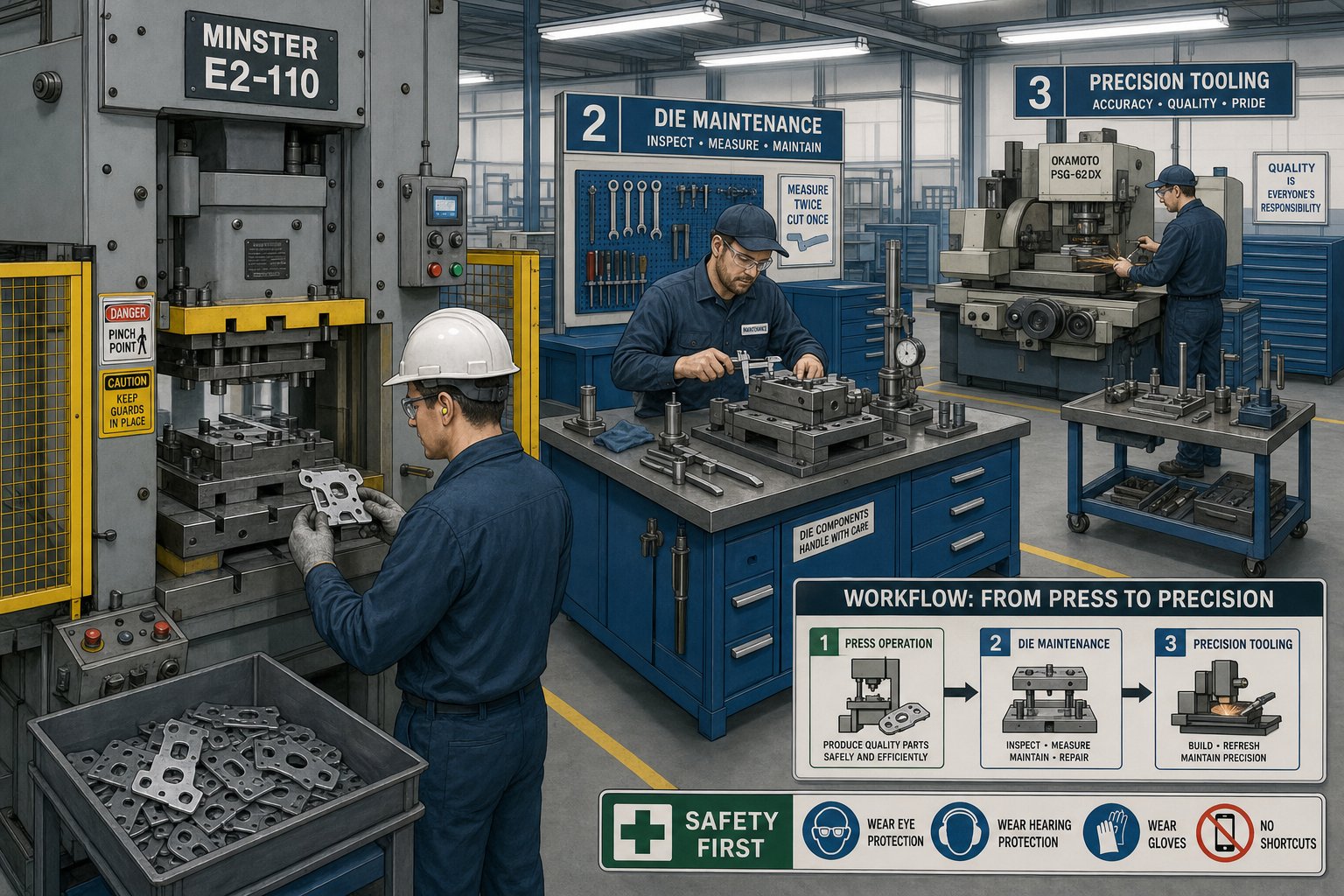
Structure without clarity creates confusion. If everyone is responsible for die condition, nobody is. A tiered die maintenance responsibility structure assigns specific tasks to specific skill levels at specific intervals, so nothing gets missed and nobody attempts work beyond their training. Think of it as three concentric rings of defense: operators catch what is happening right now, technicians address what is wearing over time, and toolmakers restore what has reached its service limit.
The table below breaks down each tier by frequency, skill requirement, and scope of work:
| Tier | Personnel | Frequency | Skill Level | Primary Tasks |
|---|---|---|---|---|
| 1 - Shift Checks | Press Operator | Every shift or every 2,000-5,000 strokes | Basic die awareness training | Visual slug retention check, lubrication level verification, strip feed alignment confirmation, listening for abnormal sounds, checking part quality against boundary samples |
| 2 - Periodic Service | Die Maintenance Technician | Every 50,000-150,000 strokes (varies by die) | Intermediate tooling knowledge, measurement skills | Punch-to-die clearance measurement, spring inspection and replacement, guide pin and bushing wear check, sharpening trigger evaluation, fastener torque verification, shim condition review |
| 3 - Major Overhaul | Toolmaker / Die Maker | Every 500,000-1,000,000+ strokes or annual | Journeyman toolmaker with full die build experience | Complete disassembly, dimensional audit of all working components, worn component replacement, timing reset, re-qualification of die to print tolerances |
Operator Daily Checks and Shift Inspections
Operators are the first line of detection. Their stamping die operator inspection checklist does not require measuring tools or disassembly. It relies on trained observation: Are slugs dropping cleanly or stacking in the die? Is lubricant reaching the strip consistently? Does the part look and feel right compared to the reference sample? Is the strip tracking straight through the pilots?
These checks take minutes but catch problems that would compound over an entire shift. A slug stuck in a die opening, for example, can destroy a punch face within a few hundred strokes if nobody notices. Art Hedrick of Dieology emphasizes that cleaning debris such as slugs, slivers, and lubricant buildup from dies is one of the most basic yet impactful maintenance activities an operator can perform.
Technician Periodic Service Tasks
Die maintenance technician responsibilities sit in the middle tier, and this is where the bulk of scheduled preventive work happens. Technicians open the die on the bench, inspect wear surfaces, measure punch-to-die clearances with feeler gauges or optical comparators, and evaluate whether cutting edges have reached their sharpening trigger point. They replace nitrogen springs or coil springs approaching end-of-life, verify that all dowel pins are seated and screws are torqued, and check cam surfaces or wear plates for galling.
The critical distinction here is that technicians service the die based on a schedule rather than a symptom. They are not reacting to a burr on a part. They are intervening at a predetermined stroke count to prevent that burr from ever appearing. This is the heartbeat of a preventive program.
Toolmaker-Level Overhaul Procedures
Toolmaker overhaul procedures for stamping dies represent the deepest level of intervention. A full overhaul means every component comes out. Each punch, die section, stripper insert, pilot, guide pin, and bushing gets measured against original design dimensions. Components that have exceeded cumulative wear limits are replaced. Timing between stations is verified and reset. The die is reassembled, spotted in, and run off to confirm it meets part print tolerances before returning to production.
This level of work requires journeyman-level skill and access to surface grinders, EDM equipment, and precision measurement tools. It should never be attempted by personnel without full die build experience. Assigning overhaul work to under-qualified staff risks introducing errors, damaging components, or creating unsafe conditions in the press.
The power of this three-tier approach is distribution. Operators handle frequent, low-complexity observations that cost almost nothing in labor. Technicians handle periodic, moderate-complexity service that keeps the die within working limits. Toolmakers handle infrequent, high-complexity rebuilds that restore the die to like-new condition. Each tier catches what the tier above it cannot see at its lower frequency, creating overlapping layers of protection against unplanned failure.
Of course, knowing who does the work and when to do it only solves half the equation. The most common task at Tier 2, sharpening, demands its own set of decision criteria to execute correctly without shortening die life.
Sharpening and Reconditioning Decision Criteria
Sharpening is the single most frequent hands-on task in any stamping die preventive maintenance program. It is also the task most often done too late, too aggressively, or without documentation. Getting it right means knowing exactly when to sharpen stamping die punches, how much material to remove, and when a component has been ground past the point of useful service.
When to Sharpen vs When to Replace
How do you know the edge needs attention? You measure the evidence it leaves behind. The most reliable trigger is burr height on stamped parts. A common burr height threshold for die sharpening in mild steel applications is 0.003 to 0.005 inches (0.076 to 0.127 mm). Once burrs consistently exceed that range, the cutting edge has rounded enough to require grinding. A maintenance guide referencing the Davinci procedure flags punch regrind review when edge wear exceeds 0.1 mm.
Other measurable indicators include changes in the shear band-to-fracture zone ratio on blanked edges. A fresh edge produces a clean shear band across roughly one-third of material thickness. As the punch dulls, that band shrinks and the fracture zone grows rougher. Dimensional drift in hole sizes or blank profiles also signals wear, since a rounded edge displaces material rather than shearing it cleanly.
Sharpening solves normal edge wear. It does not fix chipping, cracking, plastic deformation, or repeated alignment loss. If a punch shows fractures or keeps failing shortly after service, the problem has moved beyond reconditioning into replacement territory.
Grinding Best Practices for Punch and Die Sections
Die sharpening best practices start with the right equipment. A precision surface grinder, not a bench grinder, is the correct tool for restoring punch faces and die sections. The goal is controlled, parallel stock removal that maintains the original geometry of the working face.
Key principles to follow during grinding:
- Remove only the minimum material necessary. Light passes of 0.0005 to 0.001 inches per pass prevent heat buildup and preserve tool steel hardness. As Moeller Precision Tool notes, caution against introducing too much heat during grinding is essential to avoiding surface damage.
- Maintain parallelism. The punch face must remain flat and square to the punch body. Any angular deviation changes the effective clearance and creates uneven wear on the next run.
- Preserve land dimensions. Cutting punches have a straight land below the face that maintains the die clearance relationship. Grinding through that land changes the punch profile and requires reworking the clearance geometry.
- Maintain angular clearances. If the die section has angular relief behind the cutting edge, verify that the relief angle remains correct after grinding. A reduced relief angle accelerates re-dulling.
- Deburr and polish after grinding. Wire edges left from grinding can chip off during stamping and embed in parts or die surfaces. A light honing pass removes these without altering geometry.
- Shim to compensate. Every thousandth removed from a punch face shortens its effective length. Add equivalent shims behind the punch to maintain proper shut height and timing within the die.
Tracking Cumulative Stock Removal
Each sharpening cycle consumes a finite resource: the punch or die section itself. This is why documenting material removed per service matters so much. A punch originally designed with 0.060 inches of regrind life cannot be sharpened indefinitely. Once cumulative stock removal limits are reached, the component has crossed from reconditioning into replacement territory regardless of how sharp the edge looks today.
Best practice is recording the amount removed at each service directly on the die maintenance card or in your tracking system. A simple running total, punch by punch, tells your technicians exactly how much life remains. Typical regrind allowances range from 0.040 to 0.080 inches depending on punch length, material grade, and whether the design includes stepped features that limit total shortening.
When a punch reaches 75 to 80 percent of its maximum allowable removal, flag it for replacement at the next scheduled overhaul. Waiting until it is fully consumed risks running production on a component that no longer has enough land to maintain clearance, which accelerates wear on the mating die section and creates a more expensive problem than a single punch replacement.
Sharpening decisions, however, do not exist in isolation. The material flowing through the die has a direct and measurable effect on how quickly edges dull and which type of wear dominates the degradation pattern.
Material-Specific Maintenance Adjustments
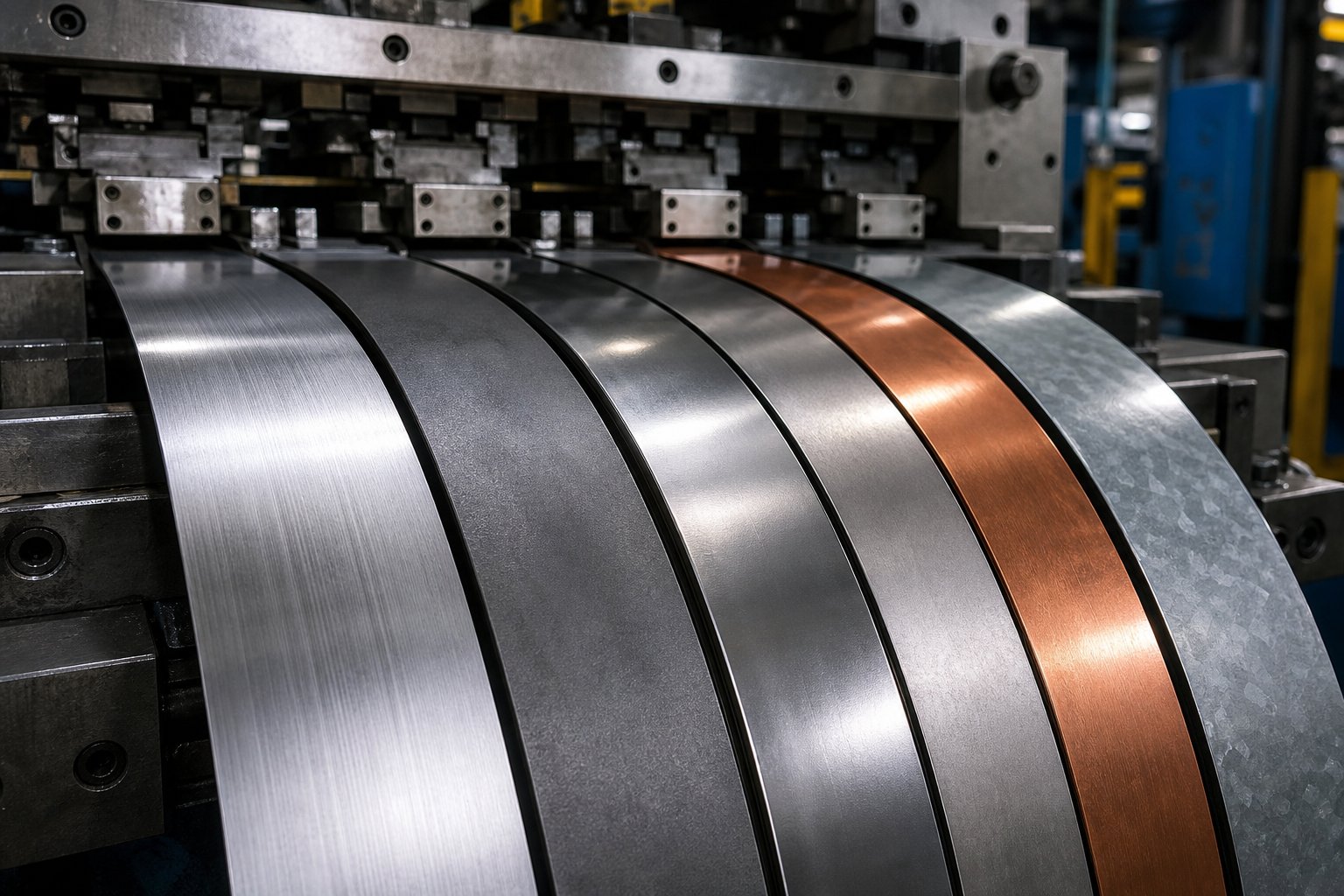
A stamping die running mild steel at 150,000 strokes between service might need attention at 80,000 strokes when the same tool runs stainless steel. The material passing through your die is not a passive participant. It actively shapes how quickly edges dull, which type of wear dominates, and where your maintenance focus should land. A single stroke-count schedule applied uniformly across all materials guarantees you are either servicing some dies too early or letting others run dangerously long.
Wear Patterns by Material Type
Different metals attack tooling in fundamentally different ways. Understanding these mechanisms helps you anticipate problems rather than react to them.
Stainless steel is one of the most aggressive materials on die tooling. Its high chromium content and tendency to work-harden during forming create adhesive wear conditions where sheet material micro-welds to the tool surface under friction and heat. This is galling, and it ranks among the top die-related problems in press shops. Once galling initiates, material transfer builds up on punch and die surfaces, scoring subsequent parts and accelerating further damage. Die maintenance intervals for stainless steel stamping must account for this adhesive mechanism by shortening lubrication checks, increasing inspection frequency for surface buildup, and triggering sharpening earlier than baseline.
Aluminum presents a different challenge. Rather than galling in the traditional sense, aluminum generates built-up edge (BUE) on cutting surfaces. Soft aluminum particles adhere to the punch face and accumulate layer by layer, effectively changing the tool geometry. BUE causes inconsistent hole sizes, rough cut edges, and increased stripping forces. Maintenance for aluminum dies focuses on cleaning protocols, removing BUE deposits before they harden, and applying surface treatments like TiN or DLC coatings that resist material adhesion. Sharpening intervals may not decrease as dramatically as with stainless, but cleaning frequency increases substantially.
High-strength low-alloy (HSLA) steels create primarily abrasive wear. Their higher hardness and oxide-scale characteristics act like sandpaper against punch surfaces, grinding away tool material progressively with each stroke. Research from the AHSS Application Guidelines shows that advanced steel grades can reach hardness values four to five times higher than mild steel, with some martensitic grades approaching the hardness of the tooling itself. HSLA steel stamping die maintenance frequency must reflect this reality. Where mild steel might allow 150,000 strokes between sharpening, HSLA grades can cut that interval by 40 to 60 percent depending on thickness and specific grade.
Mild steel (CRS/HRS) serves as the baseline. It produces moderate abrasive wear at a predictable rate, making it the easiest material to schedule around. Standard PM intervals developed for mild steel should be treated as your starting reference, not your universal rule.
The table below compares common stamped materials against their dominant wear type, recommended PM interval adjustment relative to a mild steel baseline, and where your maintenance team should focus attention:
| Material | Dominant Wear Type | PM Interval Adjustment | Primary Maintenance Focus |
|---|---|---|---|
| Mild Steel (CRS/HRS) | Moderate abrasive | Standard (baseline) | Routine sharpening, clearance checks |
| Stainless Steel (300/400 series) | Adhesive wear and galling | 30-50% shorter | Lubrication verification, surface buildup inspection, earlier sharpening, coating condition |
| Aluminum (5000/6000 series) | Built-up edge adhesion | 10-20% shorter | BUE cleaning protocols, surface treatment integrity, stripping force monitoring |
| HSLA Steel (50-80 ksi yield) | Abrasive wear | 40-60% shorter | Punch edge condition, clearance verification, spring load adequacy, coating wear |
| Advanced High-Strength Steel (DP/TRIP) | Severe abrasive + chipping risk | 50-70% shorter | Edge chipping detection, tool steel grade adequacy, coating integrity, press tonnage monitoring |
| Galvanized Steel | Abrasive (zinc oxide) + zinc buildup | 20-30% shorter | Zinc dust accumulation, slug retention, die cleaning frequency |
Adjusting PM Intervals for Material Hardness
So how do you translate this into your actual schedule? Start with your proven baseline interval for mild steel on a given die. Then apply a material multiplier based on the dominant wear mechanism and severity.
For example, if Die #247 runs reliably at 120,000 strokes between service on cold-rolled steel, and you move that tool to a stainless steel application, your adjusted interval drops to roughly 60,000 to 84,000 strokes. That is not a guess. It reflects how material hardness affects die wear through the adhesive mechanism specific to stainless, combined with the higher forming forces involved.
A few practical guidelines for adjusting your PM schedule for stamped material type:
- Do not wait for evidence. If you switch materials and keep the old schedule, you will likely discover the adjustment needed only after a failure event. Apply the shorter interval proactively on the first run.
- Refine with data. After two or three service cycles on the new material, evaluate actual wear progression. If the die sections show less wear than expected at the shortened interval, you can extend slightly. If they are already approaching limits, shorten further.
- Account for thickness changes. Thicker stock multiplies the abrasive load on cutting edges. A jump from 1.0 mm to 2.0 mm in the same material grade may warrant an additional 20 to 30 percent reduction in service interval.
- Match tool steel and coatings to the material. A D2 punch running HSLA at aggressive intervals will consume regrind allowance rapidly. Upgrading to powder metallurgy tool steels or adding PVD coatings can restore intervals closer to baseline while reducing total maintenance events over the die's life.
The AHSS Application Guidelines highlight a practical example: a chrome-plated D2 tool forming dual phase steel failed after just 50,000 parts, while the same tool steel with ion nitriding and a PVD chromium nitride coating produced more than 1.2 million parts. That is a 24x difference in tool life driven entirely by matching the surface treatment to the material's wear mechanism.
The takeaway is clear: your PM schedule is not a fixed document. It is a living framework that flexes based on what the die is actually cutting and forming. Treating all materials the same guarantees suboptimal results. Shops that tailor intervals to material behavior get longer die life, fewer surprises, and more accurate production planning.
Capturing these material-specific adjustments, tracking how each die responds to different stock, and identifying patterns across your fleet requires more than a clipboard. It requires a system for recording, analyzing, and acting on maintenance data at scale.
Digital Tracking and CMMS Integration for Die Maintenance
A paper card wired to the die shoe tells you what happened last time someone remembered to write it down. It cannot alert you when service is due, flag a die consuming twice the maintenance budget of its neighbors, or show you which failure mode keeps recurring on the same station. The gap between knowing your dies need scheduled service and actually managing that service across dozens or hundreds of tools is a data problem. Solving it requires a digital die maintenance tracking system that captures the right information, triggers the right actions, and reveals patterns invisible to manual record-keeping.
CMMS software for stamping die maintenance bridges the disconnect that plagues most shops: production knows the die ran, but the toolroom does not know how many strokes accumulated since last service. The toolroom knows the die was sharpened, but nobody recorded how much material was removed. When these gaps compound over months and years, you lose the ability to predict anything. You are back to reacting.
Essential Data Fields for Die Maintenance Records
What should your system actually capture at each service event? Not everything is equally valuable. The fields below represent the minimum data set that enables meaningful trend analysis and scheduling accuracy:
| Data Field | Purpose | Example Entry |
|---|---|---|
| Die Number / ID | Unique asset identification | D-247-A |
| Stroke Count at Service | Usage-based interval tracking | 148,200 strokes since last PM |
| Cumulative Lifetime Strokes | Total die usage history | 2,340,000 total |
| Work Performed | Task classification (sharpen, replace, inspect) | Sharpened stations 3, 5, 7; replaced spring at station 4 |
| Material Removed (per component) | Regrind life tracking | Station 3 punch: 0.002 in. removed; cumulative 0.038 in. |
| Components Replaced | Spare parts consumption and life tracking | 1x nitrogen spring P/N NS-750, 2x stripper bolts |
| Technician / Toolmaker | Accountability and skill tracking | J. Martinez |
| Material Being Stamped | Wear-rate correlation | 304 SS, 0.060 in. |
| Next Scheduled Service | Forward scheduling trigger | At 150,000 additional strokes or 4 weeks |
| Observations / Notes | Context for future technicians | Slight galling visible on form station 6, monitor next cycle |
Each field serves a specific analytical purpose. Stroke count at service enables stroke count based maintenance scheduling by comparing actual intervals against planned intervals. Material removed per component feeds cumulative regrind tracking so you know when a punch is approaching its replacement threshold. Component replacement records drive spare parts forecasting. The combination of all fields together gives you something no paper system can: a queryable, sortable, trend-ready history of every die in your fleet.
Many shops already track some of this information informally. The difference between informal and systematic is whether you can pull up Die #247's complete service history in ten seconds, see that it has consumed 40 percent more maintenance labor than comparable dies, and investigate why. That kind of visibility only exists in a structured digital system.
Using Historical Trends to Optimize PM Schedules
Raw data becomes valuable when it reveals patterns you could not see before. Here is where how to track die maintenance history digitally pays off beyond simple scheduling.
Consider three types of analysis that historical maintenance data enables:
Identifying high-maintenance dies. When every service event is logged with labor time and parts cost, you can rank your die fleet by total maintenance expense. Outliers become obvious. A die that costs three times the fleet average per 100,000 strokes may have a design flaw, a material mismatch, or a recurring issue that repeated sharpening cannot solve. Without data, that die just feels expensive. With data, you can prove it and justify engineering intervention or replacement.
Spotting recurring failure modes. If Station 5 on Die #312 has needed punch replacement at three consecutive service intervals, something systemic is happening. Maybe the clearance is wrong for the material. Maybe the punch steel grade is inadequate for the application. Maybe the strip is feeding slightly off-center and loading that station asymmetrically. Trend data surfaces these patterns so your toolmakers can address root causes rather than repeatedly replacing the symptom.
Calculating true cost per hit. Most stamping cost models account for material, press time, and labor. Few include the maintenance burden allocated per stroke. A cost per hit calculation for stamping dies divides total maintenance expense (labor + parts + downtime) by total strokes produced between overhauls. This metric lets you compare the true operating cost of similar dies, evaluate whether a more expensive die with better tool steel actually saves money over its life, and identify the point at which a die should be retired rather than overhauled again.
A MetalForming Magazine analysis reinforces this point: actual die-maintenance costs remain unknown at many organizations because repair and preventive work are often intermixed in cost tracking. Separating these categories in your digital system is essential. Reactive repair costs should decrease over time as your PM program matures, while planned maintenance costs may increase slightly but deliver disproportionate savings in avoided downtime and scrap.
Implementation Steps for Digital Tracking
Transitioning from paper cards or spreadsheets to a functional digital tracking system does not require a six-figure software investment or a year-long implementation cycle. It does require deliberate sequencing so that each step builds on the previous one. Here is a practical rollout path:
- Define your data fields. Start with the table above and customize to your operation. Resist the urge to capture everything on day one. A focused set of ten to twelve fields that people actually fill out consistently beats fifty fields that get ignored.
- Establish stroke-count triggers for each die. Use your existing baseline intervals as starting points. If a die currently gets serviced "when it looks like it needs it," estimate a conservative stroke count based on your best technician's experience and refine from there. Modern CMMS platforms can pull stroke counts directly from press PLCs, eliminating the manual logging gap that causes most scheduling failures.
- Train operators and technicians on data entry. This is where most implementations stall. If the system is harder to use than the paper card, people will not use it. Choose a platform with mobile or tablet-friendly interfaces so data entry happens at the press or the bench, not at a desktop computer across the shop twenty minutes later.
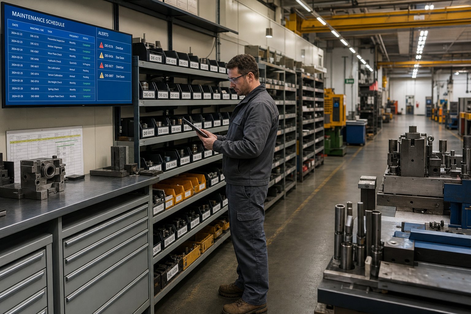
- Configure automated scheduling alerts. Set the system to notify the toolroom lead when a die approaches its service threshold. The goal is proactive pull: the toolroom plans the service window before production discovers a problem. Alerts should trigger at 80 to 90 percent of the interval so there is time to schedule the pull without disrupting the current run.
- Build reporting dashboards for continuous improvement. Once you have two to three months of data flowing in consistently, build views that answer your most important questions. Which dies cost the most per hit? Which technicians complete PMs fastest without callbacks? Which material-die combinations are consuming service intervals faster than planned? These dashboards turn raw data into decisions.
The compounding benefit of digital tracking is that each service event makes your next scheduling decision smarter. After six months, you are no longer guessing at intervals. You are setting them based on actual wear progression for each specific die running each specific material. After a year, you can forecast spare parts consumption, predict when dies will need overhauls, and demonstrate the financial impact of your PM program to management with hard numbers rather than anecdotal claims.
Still, even the best tracking system can only manage the maintenance burden a die was designed to create. Some dies demand excessive service not because of scheduling errors but because their construction makes routine maintenance harder than it needs to be. That relationship between how a die is designed and how much effort it takes to maintain over its lifetime is where long-term cost control truly begins.
How Die Design Decisions Shape Maintenance Outcomes
Every die arrives in your toolroom with its maintenance destiny already written into the steel. A die designed without thought for serviceability punishes your team at every PM interval: components that cannot be accessed without full disassembly, non-standard fasteners that require special tooling, monolithic sections that force complete replacement when only a small area wears. Conversely, a die engineered for maintainability turns routine service into a fast, predictable operation that keeps your press running and your costs controlled.
This connection between design and maintenance cost is often invisible at the quoting stage. Two dies that produce identical parts at the same cycle rate can have wildly different lifetime maintenance burdens based purely on how they were constructed. Understanding design for maintenance stamping die principles gives tooling managers the vocabulary to evaluate dies before they buy, not after they start breaking.
Design-for-Maintenance Principles in Die Engineering
What separates a die that is easy to maintain from one that fights you at every service interval? It comes down to a handful of deliberate engineering decisions made during the design phase.
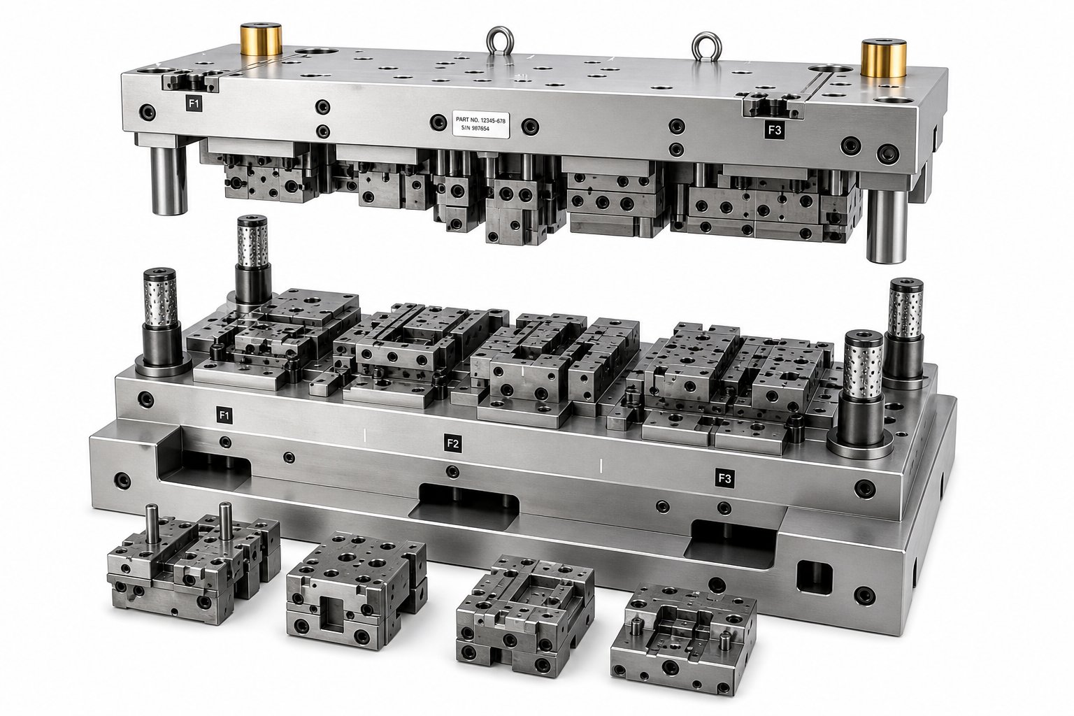
Sectioned inserts vs monolithic die construction. This is the single most impactful design choice for long-term maintainability. A monolithic die section machines the entire cutting or forming profile from one solid block of tool steel. When one area wears past its limit, the entire block must be removed, reground or replaced, and refitted. A sectioned design breaks that same profile into individual inserts, each independently removable and replaceable. When Station 5's cutting edge dulls, you pull that one insert, sharpen or swap it, and return the die to service without disturbing adjacent stations.
The engineering analysis from Jeelix frames this choice clearly: monolithic construction offers unmatched rigidity for simple geometries, but carries what they call "catastrophic maintenance costs" because any localized failure typically requires scrapping the entire costly block. Segmented designs, by contrast, reduce maintenance from catastrophic to manageable by enabling quick module swaps rather than full replacements. For dies running high volumes where PM frequency is measured in weeks rather than months, sectioned inserts pay for their added design complexity many times over.
Adequate clearance for inspection access. A die that requires removing six components to inspect one wear surface will not get inspected as often as it should. Experienced die designers build sightlines and access gaps into the die structure so that technicians can visually check critical wear areas, slug passage, and lubrication flow without full disassembly. Stripper plates with inspection windows, removable covers over high-wear stations, and strategically placed relief pockets all reduce the labor cost of every PM event.
Standardized component sizing. Imagine maintaining a fleet of 80 dies where every tool uses different spring lengths, different dowel pin diameters, different screw sizes, and different punch shanks. Your spare parts inventory explodes, and your technicians waste time hunting for the right component. Design standardization, using common spring bores, standard punch retainer dimensions, and uniform fastener sizes across your die fleet, shrinks inventory and speeds service. How die design affects maintenance costs often traces back to this unglamorous detail: can your technician grab what they need from a standard kit, or do they need to special-order every replacement?
Proper timing mark placement. Progressive dies must go back together in exact alignment. Every station's relationship to the next depends on precise reassembly after service. Timing marks, match marks, and keyed locating features that make correct reassembly obvious and incorrect reassembly physically impossible are hallmarks of stamping die engineering for maintainability. Without them, even experienced toolmakers can introduce timing errors during overhaul that create scrap on the first production run after service.
Material selection for wear resistance in high-stress areas. A die designed with uniform tool steel throughout will wear unevenly. High-stress cutting edges, cam-driven forming surfaces, and pilot nose tips all experience higher loads than surrounding structure. Specifying premium tool steels or carbide inserts at these specific locations, rather than upgrading the entire die, balances performance with cost. This heterogeneous material strategy, using D2 or powder metallurgy steels where wear concentrates and tougher A2 steel for supporting structure, extends sharpening intervals at the stations that consume the most maintenance labor.
How Maintenance Feedback Improves Future Die Builds
Design-for-maintenance is not a one-time decision. It improves continuously when maintenance data flows back to the engineering team. This feedback loop is where your digital tracking system and your die design process intersect.
Consider a practical example. Your CMMS data shows that Die #312's forming station requires punch replacement every 200,000 strokes while comparable stations in other dies last 500,000 strokes. Your toolmaker notes galling on the form surface at each service. The maintenance team has been managing this through shorter intervals and more frequent replacements. That is treating the symptom.
The feedback loop asks: why does this station gall while others do not? Maybe the forming radius is too tight for the material, generating excessive friction. Maybe the surface finish specification on that insert is too rough. Maybe the tool steel grade lacks the chromium content needed to resist adhesive wear with this particular sheet material. When engineering reviews this data and redesigns that station for the next die build, the problem disappears from future maintenance schedules entirely.
This is the principle that transforms stamping die preventive maintenance from a cost center into an intelligence system. Every service event generates information. Every pattern in that information points toward a design improvement. Shops that close this loop, feeding maintenance findings back into die engineering, progressively reduce their PM burden over successive die generations.
The feedback works across several dimensions:
- Recurring component failures signal inadequate material grade or geometry at that station, prompting redesign with harder inserts or larger radii.
- Excessive sharpening frequency at specific stations suggests clearance optimization or surface coating additions for the next build.
- Difficult access during service documented by technicians drives layout changes that improve inspection windows and component accessibility in future tools.
- Non-standard spare parts consumption highlights opportunities to standardize dimensions across the fleet during the next design cycle.
Working with a die manufacturer that considers maintenance access, component standardization, and long-term durability during the design phase reduces your PM burden from day one. Manufacturers like YICHEN approach custom stamping die builds with engineering attention to maintainability alongside production performance, recognizing that a die's true cost extends far beyond the initial purchase price into every service event across its operating life. When your die supplier treats maintainability as a design requirement rather than an afterthought, your toolroom inherits a tool that cooperates with your PM program instead of fighting it.
The lesson is clear: the easiest maintenance task to perform is the one your die was designed to support, and the cheapest failure to fix is the one that was engineered out before the steel was ever cut. But even the best-designed die still needs people, processes, and organizational commitment to maintain it properly. Building that program from the ground up, especially in shops that have never run formal preventive schedules, requires a structured approach to change management, staffing, and measurement.
Building a Preventive Maintenance Program from Scratch
Procedures alone do not create a preventive maintenance program. Procedures printed and posted on the toolroom wall do not change behavior if nobody owns them, nobody is trained to execute them, and nobody measures whether they work. The real challenge in figuring out how to start a stamping die PM program is not technical. It is organizational. You are asking people to spend time on work that prevents invisible failures, competing for attention against the very visible urgency of today's production schedule.
That tension explains why so many shops stay reactive. Production pressure always feels more immediate than prevention. Gaining buy-in from management requires speaking their language: dollars. Before proposing a formal program, gather baseline data. The Fabricator recommends compiling downtime hours, scrap costs, and customer complaints tied to die failures before requesting resources. That baseline becomes your before picture, the benchmark against which every future improvement gets measured. Managers respond to cost reduction framed in numbers they already track.
Staffing and Training Requirements
A PM program needs dedicated labor hours, not borrowed time from already-overloaded toolmakers. Estimate your staffing requirement by counting total dies in the fleet, multiplying by average service hours per PM event, and dividing by the interval frequency. If you run 60 dies that each need four hours of service every eight weeks, that is 30 technician-hours per week committed to planned maintenance alone.
Skill development follows the three-tier model covered earlier. Operators need two to four hours of training on visual inspection criteria and boundary samples. Technicians need hands-on instruction in measurement techniques, sharpening procedures, and your tracking system. Toolmakers need periodic cross-training on new die designs entering the fleet. Build a progression path: operators who show aptitude move into technician roles, technicians with deep experience advance into toolmaker positions. That pipeline keeps institutional knowledge growing rather than walking out the door with retirements.
Phased Rollout Plan for PM Implementation
Trying to launch a comprehensive program across your entire die fleet on day one invites failure. A phased rollout plan for preventive maintenance lets you prove the concept on a small scale, refine your process, and build credibility before expanding.
- Audit current die condition and maintenance history. Inspect every die in the fleet. Document current wear state, outstanding repairs, and whatever service history exists, even if it is just institutional memory from your senior toolmaker. This audit establishes your starting point.
- Establish baseline stroke-count intervals per die. Use technician experience, material-specific guidelines, and any available run data to assign an initial PM trigger to each tool. Conservative is fine. You will refine these after collecting real data.
- Assign tiered responsibilities. Formalize who owns which tasks using the operator, technician, and toolmaker structure. Post visual checklists at press stations and detailed service procedures in the toolroom.
- Build spare parts kits for each die. Effective die maintenance spare parts inventory management means pre-staging the components each die consumes during routine service: springs, punches, pilots, strippers, and fasteners. Group them in labeled bins by die number. When a die comes to the bench, its kit is already waiting. This eliminates the delay of hunting for parts mid-service and prevents technicians from skipping replacements because a component was out of stock. Set minimum stock levels for each kit based on consumption history, and review quarterly as spare parts inventory best practices recommend.
- Implement your tracking system. Whether CMMS software or a structured spreadsheet to start, begin capturing the data fields outlined in the previous chapter. Consistency matters more than sophistication at this stage.
- Review and refine intervals after initial data collection. After 90 days, pull your first reports. Compare actual wear at service against your baseline assumptions. Extend intervals where dies arrive with minimal wear. Shorten intervals where technicians find components approaching limits. This refinement cycle never truly ends. It is the mechanism that transforms a static schedule into an adaptive system.
Start with your five worst-performing dies: the ones generating the most downtime, the most scrap, or the most emergency repair calls. A successful turnaround on those tools creates visible proof that prevention works, and that proof converts skeptics faster than any policy memo.
Measuring Program Success
A program without metrics is just activity. Measuring die maintenance program success metrics confirms whether your investment in prevention is paying off or just consuming labor without moving the needle.
Three primary indicators tell the story:
- Unplanned downtime reduction. Track die-related press stoppages monthly. This is the most direct measure of PM effectiveness. Industry benchmarks suggest that mean time between failures (MTBF) should increase steadily as your program matures. If it does not improve despite consistent PM execution, your tasks may not target the right failure modes.
- Scrap rate trend. Measure reject rates attributable to tooling condition: burrs, dimensional drift, surface defects. A functioning PM program should produce a visible downward trend in tooling-related scrap within two to three quarters.
- Average die life extension. Track cumulative strokes between major overhauls for each die. As routine maintenance keeps wear controlled, the interval between expensive rebuilds should lengthen. This metric directly reflects your stamping die maintenance ROI in terms of capital preservation.
Supporting metrics worth tracking include planned maintenance percentage (what share of your total maintenance hours are scheduled versus reactive), spare parts emergency order frequency, and first-time capability after die set. World-class operations target a planned maintenance percentage above 85 percent. Most shops starting from reactive conditions will begin around 30 to 40 percent and climb from there.
Report these numbers monthly to the same managers whose buy-in you needed at the start. Nothing sustains a maintenance program like hard evidence that it is saving money. And nothing kills one faster than an inability to prove its value when budgets tighten.
Putting Your Preventive Maintenance System into Action
Stamping die preventive maintenance is not a checklist pinned to the toolroom wall. It is a system: tiered responsibilities that distribute workload intelligently, material-aware scheduling that flexes with what the die actually cuts, digital tracking that turns service events into actionable intelligence, and design-for-maintenance thinking that reduces the burden before the first stroke fires. Each element reinforces the others. A tracking system without tiered ownership generates data nobody acts on. Tiered ownership without material-specific intervals services some dies too late and others too early. The system works when all four pieces connect.
Your next move depends on where you stand today. Here is a stamping die maintenance action plan by maturity level, prioritized so you tackle the highest-impact work first regardless of starting point.
Prioritized Next Steps by Program Maturity
If you have no formal PM program:
- Audit your five worst-performing dies and document their current condition.
- Assign operator shift checks using a simple visual inspection checklist at each press.
- Set conservative stroke-count intervals based on your best technician's experience.
- Build a spare parts kit for each high-priority die so service is not delayed by missing components.
- Start tracking service events in any structured format, even a spreadsheet, to establish baseline data.
If you have basic schedules and want to optimize:
- Adjust PM intervals by material type using the wear-mechanism multipliers covered earlier.
- Implement a CMMS or digital tracking system that captures stroke counts, material removed, and components replaced at every service event.
- Calculate cost per hit for your top twenty dies to identify outliers consuming excessive maintenance resources.
- Close the feedback loop between toolroom findings and die engineering so recurring failures get designed out of future builds.
If you are ready for condition-based monitoring integration:
- Evaluate condition-based monitoring for stamping dies through press force signature tracking and tonnage variation alerts that trigger service based on measurable degradation rather than fixed intervals.
- Correlate your historical PM data with production quality metrics to identify which parameters best predict part quality drift before it reaches rejection thresholds.
- Pilot sensor-based monitoring on your highest-value progressive dies where a single crash event carries catastrophic cost.
Sourcing Dies Engineered for Long-Term Maintainability
Understanding how to reduce lifetime die maintenance costs leads to one conclusion that most shops overlook: the maintenance burden of a die is largely determined before it ever reaches your toolroom. Sectioned inserts, standardized components, accessible wear surfaces, and appropriate material selection at high-stress stations all reduce the labor and cost of every future PM event. These are design decisions made at the sourcing stage.
When evaluating new die procurement, ask whether your supplier treats maintainability as a design requirement or an afterthought. Manufacturers like YICHEN engineer custom stamping dies with attention to durability, maintenance access, and stable production performance from the initial design phase, recognizing that sourcing dies engineered for maintainability is one of the most effective long-term cost controls available to a stamping operation.
Prevention is not a destination. It is a discipline that compounds. Every service event recorded, every interval refined, every design improvement fed back into your next die build makes the system smarter and your operation more predictable. Start where you are, act on what matters most at your current maturity level, and let the data guide each next step forward.
Frequently Asked Questions About Stamping Die Preventive Maintenance
1. How often should stamping dies be serviced under a preventive maintenance program?
Service intervals depend on the die complexity and the material being stamped. A common baseline for mild steel applications is every 100,000 to 150,000 strokes. However, aggressive materials like stainless steel require 30-50% shorter intervals due to adhesive wear and galling, while HSLA steels may need 40-60% shorter intervals because of abrasive wear patterns. The most effective approach combines stroke-count triggers with calendar-based maximums so no die sits idle too long between inspections. Refine your intervals using actual wear data collected over multiple service cycles rather than relying on a single fixed number across all tools.
2. What is the difference between preventive and predictive maintenance for stamping dies?
Preventive maintenance services dies on fixed schedules based on stroke counts or calendar time, regardless of current condition. Predictive maintenance uses real-time sensor data, press force signatures, and analytics to forecast when a failure will occur and trigger service only when measurable degradation indicates it is needed. Preventive maintenance is the foundation that must be established first because it generates the historical data predictive systems need to build accurate models. Most stamping operations benefit from mastering preventive routines before investing in condition-based or predictive monitoring technology.
3. What are the signs that a stamping die punch needs sharpening?
The most reliable indicator is burr height on stamped parts exceeding 0.003 to 0.005 inches in mild steel applications. Other measurable signs include a shrinking shear band on blanked edges, dimensional drift in hole sizes or blank profiles, and increased press tonnage during cutting operations. Visual inspection may reveal a rounded or reflective cutting edge rather than a sharp defined line. If a punch shows chipping, cracking, or repeated failure shortly after sharpening, the issue has moved beyond reconditioning into replacement territory, often signaling a material mismatch or clearance problem that grinding alone cannot solve.
4. How can CMMS software improve stamping die maintenance management?
CMMS software eliminates the data gaps that keep shops reactive. It automates service scheduling by tracking stroke counts against predetermined thresholds, sends alerts when dies approach their service window, and captures detailed records of every maintenance event including material removed, components replaced, and technician notes. Over time, this data enables trend analysis that identifies high-cost dies, recurring failure modes, and true cost-per-hit calculations. Modern platforms can pull stroke counts directly from press PLCs, removing the manual logging errors that cause most scheduling failures in paper-based systems.
5. How does die design affect long-term maintenance costs?
Die construction choices made during engineering directly determine lifetime maintenance burden. Sectioned inserts allow individual component replacement without disturbing adjacent stations, reducing service time dramatically compared to monolithic blocks that require full removal for any localized wear. Standardized component sizing across a die fleet reduces spare parts inventory and speeds technician access during service. Adequate inspection clearances, proper timing marks for reassembly accuracy, and premium tool steels at high-wear stations all lower per-event labor costs. Working with manufacturers like YICHEN that engineer maintainability into custom stamping dies from the design phase helps reduce PM burden before the first production stroke fires.


