


Why Bypass Notch Science Changes How Engineers Design Stamping Dies
When you search for information on bypass notch design, you'll find plenty of resources explaining what these features do. What you won't find is a clear explanation of why they work the way they do at a physics level. That gap between function and science is exactly where costly tooling errors hide. This article bridges that gap by connecting bypass notch geometry directly to deformation mechanics and fracture science, giving tooling engineers the first-principles foundation they need to design with confidence.
What Are Bypass Notches in Progressive Dies
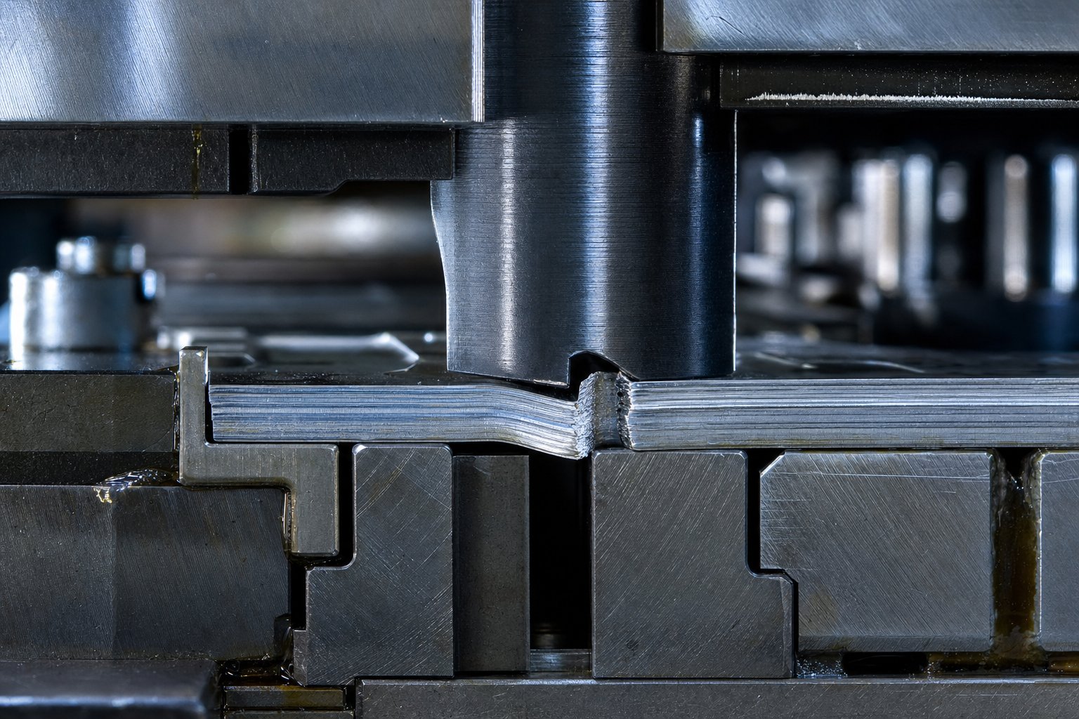
So what is stamping in the context of progressive tooling? It's a high-speed process where a metal strip advances through multiple die stations, undergoing sequential cutting, forming, and separation operations with each press stroke. Bypass notches, sometimes called pitch notches or French notches, are relief features cut into one or both edges of the carrier strip at the early stations of a progressive die. Their purpose is straightforward: they allow controlled material separation and provide solid stops that ensure accurate strip progression through every downstream station.
The purpose of bypass notches in stamping dies goes beyond simple feed control. These notches remove edge camber from slit coils, prevent overfeeding that can cause severe die damage, and establish registration references that keep parts positioned correctly across all working stations. Both negative and positive bypass notches in sheet metal stamping dies serve these registration and feed-control roles, though their geometry and shear mechanics differ significantly.
Why a Scientific Approach Matters for Tooling Engineers
If you're asking what are dies at the most fundamental level, they are precision tools that exploit controlled plastic deformation and fracture to shape metal. What is metal stamping if not applied physics? Every punch descent, every shear plane, every crack that propagates through a strip follows predictable mechanical laws. Yet most engineers design bypass notches using inherited rules of thumb, like the common 10% clearance guideline, without understanding the deformation science behind those numbers.
This approach works until it doesn't. Advanced high-strength steels, thinner gauges, and tighter tolerances all push stamping dies beyond the boundaries where generic guidelines remain valid. Engineers need to understand the underlying mechanics to adapt.
Understanding the physics of metal deformation at bypass notches enables engineers to calculate optimal parameters for any material rather than relying on trial and error. This scientific foundation transforms notch design from guesswork into predictable engineering.
The shear zone that forms during notch cutting, the fracture path that determines edge quality, and the friction forces that govern strip feeding are all governed by quantifiable principles. The sections that follow break these principles down, starting with what actually happens at the microstructural level when a punch descends into the strip.
Shear Plane Theory and Metal Deformation at Bypass Notches
Every bypass notch begins the same way: a punch descends into a strip of sheet metal, and within milliseconds, the material transitions from elastic resistance to plastic flow to outright fracture. Understanding this sequence at the stress-analysis level is what separates calculated notch design from hopeful rule-following. In the stamping manufacturing process, this shear event repeats hundreds or thousands of times per minute, making even small deviations in deformation behavior compound into measurable quality problems.
Shear Plane Formation During Notch Cutting
Imagine the punch edge contacting the strip surface. At that instant, compressive stress builds directly beneath the punch while tensile stress develops on the opposite face of the sheet. As the punch penetrates further, a narrow band of intense shear stress forms between the punch edge and the corresponding die edge. This band is the shear plane.
The shear plane does not form vertically. It develops at an angle determined by two primary factors: the material's ductility and the clearance between punch and die. More ductile materials allow greater plastic flow before fracture initiates, which shifts the shear plane angle and increases the depth of the deformed zone. Tighter clearances constrain the shear band into a narrower region, concentrating stress and promoting earlier crack initiation.
During punching stamping operations at bypass notch stations, this shear plane governs everything downstream. Its angle and uniformity dictate whether the resulting notch edge is clean or ragged, whether the strip feeds freely or binds, and whether the die process produces consistent parts across a full production run. The shear stress within this band must exceed the material's ultimate shear strength for separation to occur, and the path of that separation defines the final notch geometry.
Plastic Deformation Zones Around the Notch
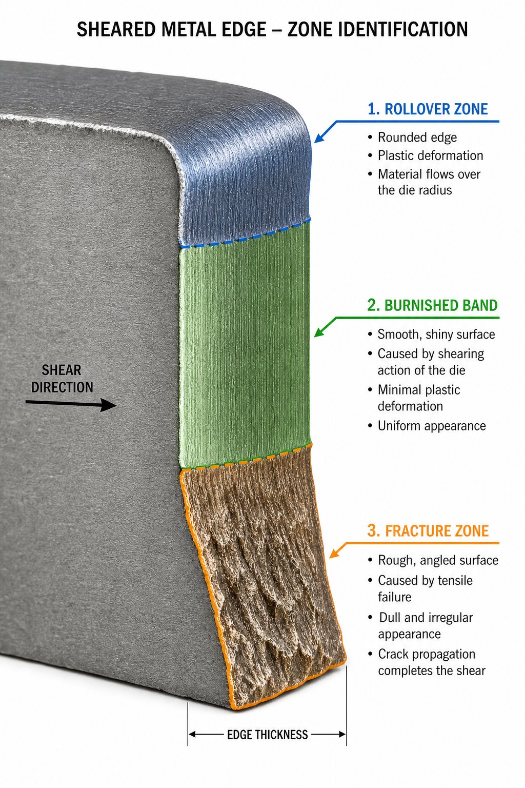
As the punch travels through the strip thickness, the cut does not happen all at once. Instead, three distinct deformation zones form sequentially, each governed by different mechanical phenomena. You can observe these zones on any sheared edge in sheet metal stamping, and their relative proportions tell you whether your clearance, punch condition, and material combination are working together or fighting each other.
- Rollover zone (elastic-to-plastic bending): When the punch first contacts the strip, the material bends and pulls inward around the punch edge before any actual cutting begins. This plastic deformation creates a rounded lip at the top surface of the notch. Rollover depth increases with larger clearances and more ductile materials. In the stamping process, excessive rollover signals that clearance may be too large or that the punch has developed wear.
- Burnished shear zone (clean cut): Below the rollover, a smooth, vertical band forms where the material shears cleanly along the punch-die interface. This burnished zone represents ideal shearing, where the metal undergoes controlled plastic flow within the narrow shear band. The ideal sheared edge shows a clearly defined burnish zone with a uniform transition to the fracture zone below it. A well-designed bypass notch maximizes this zone relative to strip thickness.
- Fracture zone (crack propagation): Once the shear stress exceeds the material's capacity for plastic flow, cracks initiate simultaneously from the punch edge and die edge and propagate inward. The fracture zone appears rougher and angled compared to the burnished surface above it. When clearance is optimized, these opposing cracks meet cleanly. When it's not, secondary shear or voids form, creating stress risers that compromise strip behavior at subsequent stations.
The proportions of these three zones shift with every variable in the stamping manufacturing process. Higher-strength materials produce less rollover and a smaller burnished zone because they fracture sooner. Work hardening at the sheared edge extends up to one-half of the metal thickness from the cut surface, reducing local ductility and altering how the strip behaves when it reaches forming stations downstream.
For bypass notches specifically, the quality signature across these three zones directly affects strip registration. An uneven burnished-to-fracture transition, or secondary shear caused by tight clearances, introduces dimensional inconsistency in the notch profile. That inconsistency translates into feed variation, and feed variation becomes misregistered parts. The fracture mechanics that control how cleanly these zones develop are the subject of the next section, where notch geometry and crack path alignment take center stage.
Fracture Mechanics Governing Notch Geometry and Crack Propagation
The three deformation zones described above do not form independently. Their relative proportions and the transitions between them are governed by fracture mechanics, the branch of engineering science that predicts how and where cracks start, how they grow, and what makes them follow a clean path versus a jagged one. For any stamping die used to cut bypass notches, fracture mechanics determines whether you get a precise, repeatable notch profile or an edge riddled with stress risers and dimensional scatter.
Crack Initiation and Propagation in Notch Shearing
Here's what happens inside the strip at the critical moment of separation: cracks initiate simultaneously from two locations. One starts at the punch cutting edge, propagating downward and inward. The other starts at the die cutting edge, propagating upward and inward. These two crack fronts race toward each other through the remaining material thickness that sits between the burnished zone and the bottom of the strip.
When clearance is set correctly, the two crack fronts align and meet cleanly. The result is a smooth fracture zone with no voids, no secondary shear, and no edge damage. Research on sheared edge quality in AHSS grades confirms that the ideal condition shows a uniform transition from the burnish zone to a smooth fracture zone. In die stamping operations where bypass notches must maintain consistent geometry across hundreds of thousands of press strokes, this clean crack meeting is essential for repeatable strip registration.
When clearance is too small, the crack fronts bypass each other. Instead of meeting, they propagate past one another, leaving a thin web of uncut material that tears in secondary shear. This secondary shear creates micro-cracks, rough edges, and voids that act as propagation sites for future edge fractures. When clearance is too large, cracks still initiate from punch and die edges, but the increased distance between them allows excessive plastic deformation before the fronts meet. The material bends and rolls rather than fracturing cleanly, producing heavy rollover and an irregular burr.
How Notch Geometry Governs Fracture Behavior
Crack initiation doesn't happen uniformly along the entire punch-die interface. It begins at points of maximum stress concentration, and notch geometry directly controls where those points occur and how intense the stress field becomes.
Consider the key geometric features of negative and positive bypass notches in sheet metal forming stamping dies: notch width, notch depth, and internal corner radii. Each parameter influences the local stress intensity factor, which quantifies the magnitude of the stress field at a crack tip.
- Notch width determines the span of the shear plane. Wider notches distribute shear force over a longer cutting edge, reducing peak stress per unit length but requiring greater total punch force.
- Notch depth controls how much material is removed from the carrier strip. Deeper notches increase the moment arm available for bending at the notch root, which can promote unwanted deformation if not matched to strip thickness.
- Corner radii are where fracture science gets critical. Sharper internal corners concentrate stress dramatically, following the classic relationship where stress intensity increases as the radius approaches zero. This concentration actually helps initiate fracture cleanly at the intended location, promoting a defined crack path. But there's a tradeoff: excessive sharpness focuses so much stress on the die stamp edge that premature wear, chipping, and micro-cracking of the tooling itself become the limiting failure mode.
For precision die stamping applications, corner radius selection becomes a balancing act. You want enough sharpness to drive clean crack initiation in the strip while preserving enough tool edge integrity to maintain that geometry over production volumes. Die stamps used in high-volume progressive tooling must sustain this balance across millions of cycles, which is why corner radius optimization requires understanding both workpiece fracture behavior and tool material fatigue limits.
Burr Formation Mechanics at Bypass Notches
Burr is not a random defect. It's a direct mechanical consequence of incomplete fracture. When the shear zone fails to propagate cracks cleanly through the full strip thickness, the remaining material doesn't separate. Instead, it deforms plastically, stretching and extruding beyond the nominal cut edge to form what we recognize as burr.
The mechanism works like this: if the opposing crack fronts from punch edge and die edge don't meet because of misaligned clearance, worn tooling, or excessive ductility, a thin ligament of material persists. As the punch continues its stroke, this ligament gets stretched and torn rather than sheared. The result is a raised edge of plastically deformed metal that extends past the intended cut line.
With conventional mild steels, burr height increases continuously with tool wear and increasing clearance, making it a reliable indicator for tool maintenance scheduling. Higher-strength materials behave differently. AHSS grades tend to fracture with less rollover and maintain relatively constant burr height because their lower ductility limits how far the material can plastically extend before breaking off. This means burr height alone isn't a sufficient quality indicator for modern stamping die applications that process advanced materials.
When punch-to-die clearance is optimized, crack fronts from both cutting edges propagate along converging paths that meet within the strip thickness. This alignment of the fracture paths is the single most important variable governing clean notch separation, burr minimization, and consistent edge geometry in bypass notch design.
The practical implication is clear: clearance selection for bypass notches cannot be a fixed percentage applied universally. It must account for the specific material's fracture toughness, ductility, and work-hardening characteristics, all of which shift the point at which cracks initiate and the angle at which they propagate. Those material-specific variables are precisely what the next section addresses.
Material Properties That Drive Bypass Notch Design Parameters
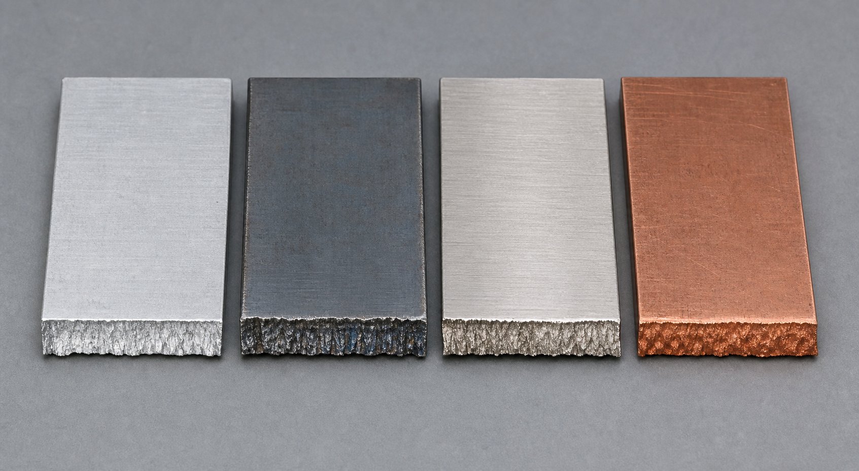
Fracture path alignment depends on clearance, but clearance itself is not a standalone variable. It's a response to material behavior. Two strips of identical thickness but different alloys will produce completely different shear zone signatures, burr profiles, and registration accuracy when processed through the same bypass notch punch. The reason is that material properties dictate how the metal deforms, when it fractures, and how much it springs back after the punch retracts. Engineers who treat all materials the same end up troubleshooting problems that were designed into the die from the start.
How Grain Direction and Anisotropy Affect Notch Performance
Rolled sheet metals are not uniform in every direction. The rolling process elongates the crystalline grain structure, creating directional properties known as anisotropy. This matters for bypass notch performance because the orientation of the notch cut relative to the grain direction changes how the shear zone develops and how cleanly fracture propagates.
Cutting bypass notches perpendicular to the grain direction generally produces a cleaner fracture zone with less burr, because bending and fracture resistance improve when operations cross the grain rather than run parallel to it. Notches cut parallel to the rolling direction encounter material that is more prone to cracking along pre-existing grain boundaries, which can produce an irregular fracture surface and inconsistent notch profiles.
In steel sheet stamping operations, coil strip typically feeds through the progressive die in the rolling direction. This means bypass notches cut into the strip edges are oriented perpendicular to the grain, which is generally favorable. But when slit coils are used, or when strip layout positions notches at varying angles to grain flow, the anisotropy effect becomes significant. Shear zone proportions can shift by 10-15% in burnished depth simply by changing the cut orientation relative to grain. For metal stamping components requiring tight registration tolerances, specifying grain direction on the coil purchase order is not optional but essential.
Material-Specific Notch Design Considerations
The scientific basis for bypass notch parameters shifts substantially across common stamping materials. Ductility governs how deep the rollover zone extends. Work hardening rate determines how quickly punch force increases as the tool wears. And fracture toughness controls whether the material separates cleanly or tears into burr. The table below compares these effects across the materials engineers encounter most frequently in stamped sheet metal applications.
| Parameter | Aluminum Alloys | High-Strength Steel | Stainless Steel | Copper Alloys |
|---|---|---|---|---|
| Ductility influence on rollover zone depth | Moderate rollover; varies significantly by grade and temper | Shallow rollover; fractures earlier due to lower ductility | Deep rollover; high ductility before fracture initiation | Variable; depends heavily on alloy and temper (e.g., phosphor bronze vs. brass) |
| Work hardening effect on punch force | Low work hardening; punch force stays relatively stable | Moderate to high; AHSS may require clearances up to 21% per side for clean break | Very high; austenitic grades may need up to 3x the force of low-carbon steel | Moderate; increases with zinc content in brasses |
| Recommended clearance range (% of thickness per side) | 8-12% | 12-21% (increases with tensile strength) | 12-16% (10% produces excessive burr) | 8-12% (dependent on temper) |
| Typical burr tendency | Moderate; soft material deforms rather than fractures cleanly | Low to moderate; fractures decisively at proper clearance | High; the common 10% clearance guideline produces worst-case burr height | Low for soft tempers; increases with hardness |
A few things stand out here. The aluminum stamping process demands wider clearances not because aluminum is hard to cut, but because its low work hardening means the material stretches rather than fractures when clearance is too tight, producing stringy burr rather than a clean edge. Stainless steel presents the opposite problem: its high work hardening rate means the shear zone strengthens as the punch penetrates, requiring significantly more force and a clearance approach that many engineers get wrong by defaulting to the 10% rule.
For stamped steel in high-strength grades, the science is clear. Research on advanced high-strength steels shows that materials with low yield-to-tensile strength ratios require greater punch-to-die clearance to provide the mechanical leverage needed to break the slug cleanly. This applies directly to bypass notch design: these same materials need more room for crack fronts to propagate at their natural angle without creating secondary shear.
Springback and Elastic Recovery Effects on Notch Tolerances
Here's a variable that many tooling engineers overlook in bypass notch design: after the punch retracts and the strip advances, the notch doesn't stay exactly the size it was cut. Elastic recovery, commonly called springback, causes the notch opening to change dimensionally as stored elastic strain releases from the surrounding material.
The mechanism is straightforward. During notch cutting, material adjacent to the shear zone undergoes plastic deformation, but the surrounding strip retains elastic strain. When the punch withdraws, this elastic strain releases and changes the geometry. For bypass notches, the practical effect is that the notch opening narrows slightly as the elastically compressed material around the cut springs back toward its original state.
The magnitude of this dimensional shift depends on the material's yield strength and elastic modulus. Higher-strength steels store more elastic energy before yielding, so they spring back more. AHSS grades can produce springback significant enough to affect strip registration accuracy at downstream stations if not accounted for in the notch width calculation. An AISI study confirmed that angular change and dimensional deviation increase with yield strength, which means bypass notch tolerances must be grade-specific rather than generic.
For progressive dies processing high-strength stamped sheet metal, the design implication is that notch width at the punch must be slightly oversized relative to the nominal registration dimension. The overshoot compensates for elastic recovery so that the final notch geometry, after springback has occurred, matches the intended feed pitch. Getting this compensation right requires knowing the specific alloy's elastic modulus, yield strength, and the constraint conditions around the notch, variables that differ for every material in the table above.
Material properties set the boundary conditions for every aspect of bypass notch performance. But there's another parameter that mediates between material behavior and notch function: the punch-to-die clearance ratio. And for bypass notches specifically, the clearance logic diverges from standard blanking rules in ways that trip up even experienced die designers.
Clearance Science for Bypass Notches vs. Standard Blanking
The standard recommendation for punch-to-die clearance is approximately 10% of the material's stock thickness per side. That number works well for conventional blanking where the goal is a cleanly separated slug and a quality part edge. But bypass notches serve a fundamentally different purpose, and applying blanking clearance logic to them introduces problems that show up as feed inconsistency, binding, and premature die wear. Understanding why requires looking at what each operation actually demands from the shear event.
Standard Blanking Clearance vs. Bypass Notch Clearance
In blanking, the objective is complete slug separation with a controlled edge finish on the retained part. Clearance is optimized so that crack fronts from punch and die edges meet cleanly, producing the best possible ratio of burnished-to-fracture zone on the cut edge. Edge quality drives the clearance decision because the cut edge becomes a functional feature of the finished part.
Bypass notches flip that priority. The notch edge is not a product feature. It's a process feature. Its job is to allow unobstructed strip progression while maintaining enough engagement with pitch stops or guide rails to control registration. Edge finish is secondary. Feed accuracy and consistent notch geometry across millions of strokes are primary. This functional difference means that among the various types of stamping dies, progressive tools with bypass notches require clearance logic tuned for stripping behavior and feed mechanics rather than edge aesthetics.
In practice, this often means bypass notch clearances run slightly larger than blanking clearances for the same material and thickness. The reason is mechanical: a tighter clearance increases stripping force because the punch must overcome greater frictional contact with the sheared surface during retraction. In blanking, that tradeoff is accepted for better edge quality. In bypass notch cutting, elevated stripping force pulls the strip upward during punch withdrawal, disturbing feed positioning and potentially lifting the strip off lifter rails.
Force Balance and Strip Feed Accuracy
Think of the strip as a free body moving through the die. At each press stroke, forces act on it from multiple directions: feed force pushing it forward, pilot pins correcting lateral position, lifter rails supporting it vertically, and the notch punch imposing downward shear followed by upward stripping force. Feed accuracy depends on these forces staying balanced and predictable.
The bypass notch contributes to this balance in two ways. First, the notch removal creates clearance for the strip to advance past stationary die features without interference. Second, the notch geometry interacts with guide surfaces and pitch stop mechanisms that prevent overfeeding and establish registration. If the notch is cut too aggressively with excessive clearance, the resulting sloppy edge geometry reduces the precision of engagement with these stops. If clearance is too tight, stripping forces disturb the strip's seated position on lifter rails between strokes.
Lateral drift compounds this problem. A metal stamping die that cuts bypass notches with uneven clearance side-to-side produces asymmetric stripping forces. The strip gets pulled slightly toward the tighter side during each punch retraction, accumulating positional error that manifests as misregistration at downstream forming and cutting stations. For steel stamping dies running high-speed production, even a few microns of drift per stroke compounds across stations into reject-level dimensional error.
Calculating Clearance for Notch Function
The engineering logic for bypass notch clearance starts with the same foundation as blanking: clearance equals a percentage of material thickness, applied per side. The formula is straightforward, with clearance per side calculated as the recommended percentage multiplied by stock thickness. But the recommended percentage for notch function shifts based on several interacting variables that differ from blanking considerations.
Thinner materials require proportionally larger clearance percentages. The reason is that at small absolute clearances, stripping force becomes disproportionately high relative to the strip's stiffness. A 0.2mm strip at 10% clearance has only 0.02mm per side. Any punch wear or thermal expansion closes that gap rapidly, spiking stripping forces and degrading feed. Increasing to 12-15% provides a functional buffer without sacrificing notch geometry. Thicker materials, conversely, tolerate tighter ratios because the absolute clearance dimension provides inherent margin against these effects.
The key variables that govern bypass notch clearance selection in stamping die design include:
- Material thickness: Determines the absolute clearance dimension and stripping force magnitude
- Material tensile strength: Higher-strength materials require greater clearance to achieve fracture without excessive force buildup
- Strip width and carrier stiffness: Thinner, narrower carriers are more sensitive to stripping-force disturbance, demanding looser clearance
- Press speed: Higher speeds increase dynamic stripping forces and reduce the time window for strip re-seating between strokes
- Punch length and unsupported span: Longer punches deflect more under lateral load, effectively reducing clearance on one side during cutting
- Lubrication conditions: Lubricant reduces stripping friction, which can allow tighter clearances without the feed-disturbance penalty
- Notch geometry and aspect ratio: Deeper, narrower notches concentrate lateral thrust on the punch, requiring backup support and influencing effective clearance behavior
Modern development in sheet metal stamping dies has pushed clearance recommendations beyond the traditional 10% standard. Research indicates that 11-20% clearances can considerably reduce tooling strain during piercing and extend operational life, a finding that applies directly to bypass notch punches that must maintain geometry over extended production runs. For steel stamping dies processing AHSS grades, starting at the upper end of this range and validating through trial samples is more reliable than defaulting to the outdated 10% rule.
Clearance is not the only geometric variable that determines notch performance. The overall shape of the notch, whether rectangular, tapered, or radiused, interacts with clearance to define the complete stress distribution, force profile, and wear pattern at the cutting station.
Comparing Notch Geometries with Scientific Reasoning
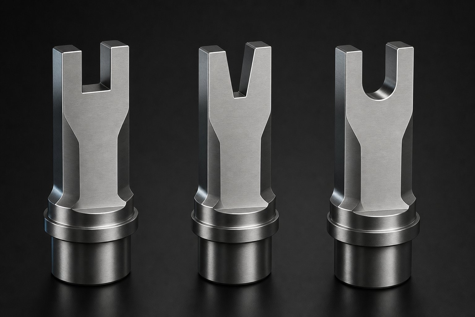
Clearance defines how the shear event unfolds through the strip thickness, but the shape of the notch itself determines where stress concentrates, how force distributes across the cutting edge, and how quickly the die wears under production loads. Three primary notch geometries dominate metal stamping die design for progressive tooling: rectangular, tapered, and radiused profiles. Each produces a distinct mechanical response in the strip, and the science covered in previous sections explains exactly why one geometry outperforms another for a given application.
Rectangular Notch Geometry and Stress Distribution
The rectangular notch is the workhorse profile in bypass notches sheet metal forming applications. Its straight parallel edges create a uniform shear front that engages the full notch width simultaneously. From a stress distribution standpoint, this means the cutting force spreads evenly along both lateral edges of the punch, producing a balanced load that resists the punch deflection problems that plague asymmetric geometries.
Sounds straightforward, but there's a mechanical tradeoff. Because all points along the cutting edge engage the strip at the same instant, the peak punch force is the highest of any geometry for a given notch width. The press sees a sharp force spike rather than a gradual ramp. For standard-thickness materials with moderate feed forces, this instantaneous engagement works fine. The strip's inertia and the die's structural stiffness absorb the impact without issue. But when you move into thicker gauges or higher-strength materials, that force spike translates to accelerated punch wear at the corners and increased press energy consumption per stroke.
The stress concentration at internal corners of rectangular notches follows predictable patterns. The 90-degree intersection of the notch's side wall and base creates a geometric discontinuity where stress intensity factors climb sharply. In the workpiece, this promotes clean fracture initiation at those corners, which is desirable. In the die itself, those same corners become the first failure points where chipping and edge rounding develop over production volume.
Tapered and Radiused Notch Profiles
Tapered notches solve the force-spike problem by distributing shear progressively rather than simultaneously. The angled entry means the punch tip contacts the strip first at its narrowest point, then widens as it descends. This staggers the shear initiation along the cutting edge, producing a ramped force profile that peaks lower and sustains longer than the rectangular equivalent.
Why does this matter for stamping design? Progressive shear reduces the instantaneous load on both the punch and the press structure. For high-speed operations where dynamic forces compound mechanical vibration, tapered notches dampen the shock loading that causes premature fatigue in die components. They also reduce the snap-through energy released when fracture completes, which means less strip disturbance during the separation event. In transfer stamping systems and high-speed progressive dies alike, this smoother force profile translates to more stable strip behavior at the moment of notch completion.
Radiused notch profiles take a different approach. Instead of modifying the entry angle, they eliminate the sharp internal corners where stress concentration peaks. A radius at the notch root spreads the stress field over a larger area of the die surface, following the same principle demonstrated in FEA studies showing that increasing fillet radius from 0.01" to 0.08" can reduce peak stress by over 70%. For the die, this means dramatically slower wear progression at the notch corners. For the workpiece, the reduced stress concentration at the notch root means slightly less decisive crack initiation, which can increase the fracture zone roughness marginally but extends die life substantially.
Many production tooling applications combine both features: a tapered entry profile with radiused internal corners. This hybrid geometry captures the progressive shear advantage while simultaneously extending die life at the highest-wear locations.
Selecting Geometry Based on Application Science
Choosing between these profiles isn't a preference decision. It's a calculation driven by the same deformation and fracture principles covered earlier. Three variables guide the selection:
- Material ductility determines fracture behavior at corners. Ductile materials like soft copper alloys tolerate sharp rectangular corners because the material flows plastically rather than cracking the die. Brittle or high-strength materials concentrate stress back into the tool at those same corners, demanding radiused profiles to distribute load and prevent chipping.
- Strip thickness governs whether progressive shear (tapered) outperforms simultaneous shear (rectangular). Thicker strips generate proportionally higher peak forces during simultaneous engagement, making the tapered geometry's force-ramping advantage more significant above approximately 1.5mm thickness.
- Production volume dictates acceptable die wear patterns. For automotive stamping dies running millions of cycles, even modest stress concentration at notch corners compounds into measurable geometry change. Radiused profiles extend resharpening intervals and total die life, making their slightly higher initial machining cost irrelevant against the maintenance savings.
The table below provides a structured comparison across the critical parameters that metal stamping design engineers evaluate during notch geometry selection:
| Parameter | Rectangular | Tapered | Radiused |
|---|---|---|---|
| Stress concentration factor at notch corners | High (sharp 90-degree transitions concentrate stress significantly) | Moderate (angled edges reduce abrupt geometry change) | Low (radii distribute stress over broader tool surface area) |
| Die wear pattern | Concentrated at corners; early chipping and rounding at notch root intersections | Distributed along tapered edges; gradual flank wear rather than localized failure | Diffuse; wear spreads across curved surfaces, extending resharpening intervals |
| Optimal material pairings | Mild steel, copper alloys, and ductile aluminum grades at standard thickness | High-strength steel, thicker gauges, and materials requiring high shear force | AHSS, stainless steel, and any high-volume application regardless of material |
| Strip feed force profile | Sharp force spike with abrupt snap-through at fracture completion | Gradual ramp with reduced peak force and lower snap-through energy | Similar to rectangular in timing but reduced corner-induced vibration |
| Best-use application | Standard progressive dies with moderate production volumes and conventional materials | High-speed progressive dies, thick-gauge applications, and vibration-sensitive tooling | High-volume automotive stamping dies, AHSS processing, and dies requiring maximum service life between maintenance |
In metal stamping die design practice, the geometry decision often combines elements from multiple profiles. A notch might use a rectangular base profile for maximum material removal efficiency while incorporating corner radii at the root to protect die life. Or a tapered entry might feed into a straight-walled section for precise registration engagement. The science supports these hybrid approaches because each geometric feature addresses a specific mechanical demand independently.
Engineers working through these geometry decisions for specific material and production combinations benefit from design consultation that connects simulation results to production-validated tooling. YICHEN's custom stamping die solutions help engineers select and validate notch geometry for specific material and production requirements, bridging the gap between theoretical optimization and proven die performance through their collaborative design process.
Geometry and clearance together define the static mechanics of bypass notch cutting. But once the strip starts moving through the die at production speed, another force enters the equation: friction. How the notched strip edge interacts with guide surfaces, lifter rails, and lubricant films during feed progression introduces tribological variables that no geometry decision alone can solve.
Tribology of Strip Feeding and Bypass Notch Interaction
Geometry and clearance control what happens during the cut. Friction controls what happens after it. Every time the strip advances through a progressive die, the notched edges slide across lifter rails, guide surfaces, and pitch stops. That sliding contact is governed by tribology, the science of friction, wear, and lubrication between interacting surfaces. For stamping die components in high-speed progressive tooling, tribological behavior at bypass notches directly determines whether the strip feeds cleanly or drifts into misregistration. Yet this is the one aspect of notch design that almost no technical resource addresses.
Friction Forces at the Notch-Die Interface
Imagine the strip advancing one pitch length between press strokes. The notched edges don't float freely through space. They ride on lifter rail surfaces, brush past guide posts, and engage pitch stops that control registration. At each of these contact points, the coefficient of friction between the strip edge and the die surface determines how much resistance the feed system must overcome to move the strip forward.
For a smooth, well-burnished notch edge sliding on a polished hardened lifter rail, the friction coefficient stays low and predictable. The feed mechanism advances the strip with minimal drag, and pilot pins correct any minor positional scatter without fighting residual friction forces. This is the ideal condition, and it persists as long as the notch edge geometry remains consistent.
Burr changes everything. As punch wear progresses during production, burr height at the notch edge increases incrementally. That raised burr lip acts as a micro-plough dragging across the lifter rail surface. The friction coefficient jumps because contact transforms from smooth surface-on-surface sliding to an abrasive edge-on-surface interaction. Burr direction matters too. A burr oriented downward toward the lifter rail creates direct abrasive contact during every feed stroke. A burr oriented upward contacts the stripper plate instead, transferring drag force to a different interface and potentially disturbing strip liftoff timing.
The surface condition of the metal stamping tooling compounds this effect. Lifter rails that develop wear tracks from repeated strip contact lose their surface finish in localized zones. Those worn tracks increase friction for subsequent strips and create preferential channels that resist lateral correction by pilots. In stage tooling configurations where multiple stations operate sequentially, friction buildup at early-station notch contacts propagates positioning errors into every downstream operation.
Lubricant Behavior in Notch Zones
Lubricant doesn't distribute uniformly across a notched strip. The notch cavity itself acts as a reservoir, trapping lubricant that would otherwise spread across the strip surface. At moderate press speeds, this pooling is benign or even beneficial. The trapped lubricant wicks onto guide surfaces during feed advancement, reducing friction at contact points.
At high press speeds, the physics shift. Rapid strip acceleration and deceleration during each feed cycle creates hydraulic pressure spikes in lubricant pooled within notch cavities. High-speed stamping generates significant frictional heat and reduces contact time between tooling and workpiece, which changes lubricant viscosity dynamically during each stroke. Lubricant trapped in deep notch profiles can get pressurized during rapid strip deceleration, creating a hydraulic cushion effect that momentarily lifts the strip edge off its guide surface. When that pressure releases, the strip drops back onto the rail with a micro-impact that disturbs its seated position.
The opposite problem, lubricant starvation, occurs at the notch edges themselves. The shearing action during notch cutting wipes lubricant off the freshly cut surfaces. The burnished and fracture zones emerge from the cutting event essentially dry, with whatever lubricant film existed on the strip surface disrupted by the plastic deformation. These dry edges then contact guide surfaces with elevated friction until lubricant migrates back from adjacent areas.
Notch depth and geometry directly influence this lubricant distribution pattern. Deeper notches trap more lubricant volume, amplifying hydraulic effects at speed. Rectangular notch profiles with sharp corners create stagnation zones where lubricant pools rather than flowing. Tapered profiles promote lubricant drainage away from the cavity during feed movement, reducing hydraulic buildup but potentially leaving the notch root starved. For stamping tooling designed to run at high stroke rates, lubricant management around bypass notches requires the same engineering attention as lubricant delivery to forming stations.
Feed Accuracy as a Function of Notch Friction
Feed accuracy is the measurable outcome where tribology meets part quality. A progressive die can have perfect clearances, optimal notch geometry, and correct pilot timing, yet still produce misregistered parts if friction forces at the bypass notches become asymmetric.
Asymmetry develops naturally during production. One side of the die wears faster due to slight alignment differences, thermal gradients, or lubricant distribution inconsistencies. When the notch punch on one strip edge wears ahead of the other, it produces different burr heights on opposite sides of the carrier. That burr differential creates unequal friction forces during strip advancement. The strip experiences more drag on one edge than the other, producing a net lateral force that pushes it sideways, one micro-increment per stroke.
Lubrication consistency affects feeding because changes in oil type, viscosity, or application rate can alter friction enough to impact progression. In metal stamping tooling systems, this means a lubricant delivery nozzle that gets partially blocked on one side of the strip doesn't just increase wear locally. It creates a friction imbalance that drives strip drift. Pilots can correct for small positional errors, but they work within a finite engagement window. Once cumulative drift exceeds pilot clearance capacity, the strip misregisters and parts go out of tolerance.
The following friction-related failure modes commonly develop at bypass notches in progressive die operations:
- Asymmetric burr growth: Uneven punch wear produces different burr heights on opposite strip edges, creating lateral drag imbalance during feed advancement and progressive strip drift toward the higher-friction side.
- Lifter rail galling: Burr edges repeatedly abrade the same rail surface, transferring workpiece material onto the rail and creating a high-friction buildup zone that resists smooth strip progression.
- Lubricant-induced hydraulic lift: Excess lubricant trapped in deep notch cavities pressurizes during rapid feed deceleration, momentarily lifting the strip off its guide surface and allowing lateral displacement before re-seating.
- Thermal friction escalation: Frictional heat at notch-rail contact points reduces lubricant viscosity locally, which decreases film thickness, increases metal-to-metal contact, and generates more heat in a self-reinforcing cycle that accelerates wear.
- Guide surface wear channeling: Repeated strip contact at consistent positions wears grooves into guide surfaces, creating tracks that resist pilot-driven lateral correction and lock the strip into a drifted position.
- Stripping-force-induced strip lift: Elevated friction between punch and notch wall during retraction pulls the strip upward off lifter rails, disturbing its vertical position and altering the contact geometry for the next feed stroke.
Each of these failure modes develops gradually. The strip doesn't suddenly jump out of registration. Instead, friction forces shift incrementally over thousands of strokes until the cumulative positional error crosses a quality threshold. Operators may first notice unstable strip progression, inconsistent pilot engagement, or abnormal press vibration before visible part defects appear. By that point, the tribological degradation has been building for some time.
Monitoring friction behavior at bypass notches requires tracking indirect indicators: feed force trends, pilot hole elongation patterns, burr height measurements during scheduled checks, and lubricant consumption rates per side of the die. These signals, interpreted through the lens of tribological science, provide early warning before feed accuracy degradation reaches reject-producing levels.
Friction is inherently difficult to model from first principles alone because it depends on surface conditions that evolve during production. This is exactly where computational methods earn their value: finite element analysis can simulate the stress and deformation mechanics of the notch cut itself, while tribological modeling informed by production data validates whether the resulting surface will behave predictably across the die's service life.
Validating Bypass Notch Design with FEA and Simulation
Shear plane theory, fracture mechanics, material science, and tribology provide the governing equations. But equations alone don't tell you whether a specific notch width, clearance, and geometry combination will perform as predicted in a real progressive die running at production speed. Finite element analysis bridges that gap. It takes the first-principles science covered throughout this article and translates it into visualizable, quantifiable predictions that engineers can validate before a single piece of tool steel gets machined.
FEA Simulation of Notch Shear Zones
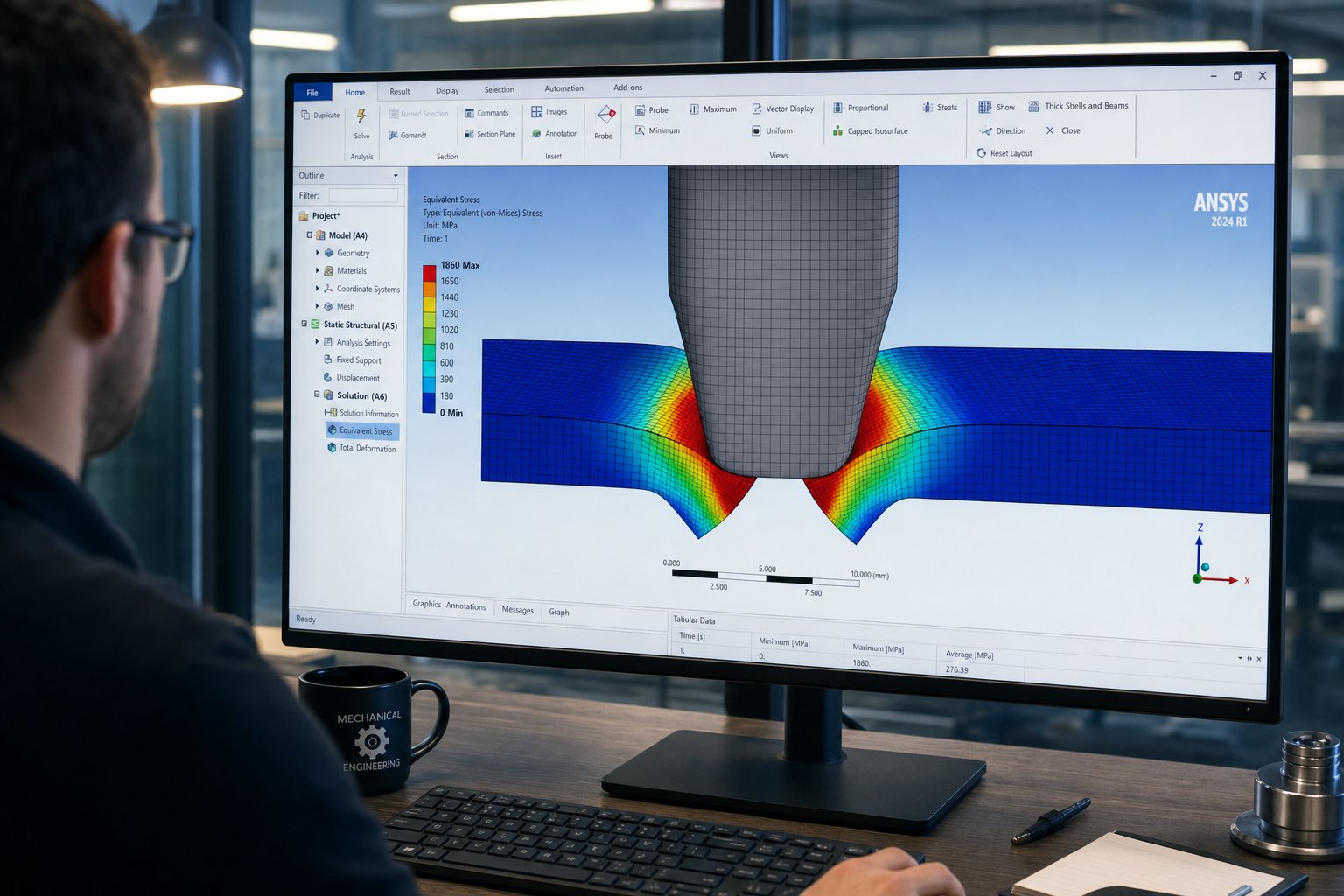
When you model a bypass notch cutting event in FEA, the software discretizes the strip material into thousands of small elements, then solves the stress-strain equations for each element as the punch descends incrementally through the strip thickness. The result is a detailed map of shear band formation, plastic strain accumulation, and damage progression that mirrors the three physical zones described earlier: rollover, burnish, and fracture.
A 2024 study published in Heliyon demonstrated this approach using ABAQUS/Explicit to simulate sheet metal blanking of DP600 steel. The researchers modeled the complete cutting cycle including punch penetration, sheet separation, and stripping, achieving cut edge zone predictions within 4-14.6% of experimental measurements. Their FEA model captured how increasing clearance from 6% to 15% delayed crack initiation, expanded the burnished zone, and reduced the fracture zone, exactly the relationships that shear plane theory predicts but that would require dozens of physical trial runs to quantify experimentally.
For metal stamping dies used in bypass notch stations, this simulation capability means you can visualize the fracture path alignment before cutting any tooling. You can confirm whether your selected clearance produces converging crack fronts or whether it drives secondary shear. You can quantify stripping forces and push forces at different clearance values, data that directly informs the feed-accuracy analysis covered in earlier sections. The same study showed that push force decreased by 77.7% and stripping force by 73.2% when radial clearance increased from 6% to 12%, a dramatic sensitivity that would be invisible without simulation.
Simulation-Driven Optimization for Novel Materials
Where simulation becomes indispensable is with materials that lack established empirical guidelines. Advanced high-strength steels, dual-phase grades, and exotic alloys used in automotive and aerospace stamped metal parts don't conform to the rules of thumb developed for mild steel decades ago. Their complex microstructures produce non-linear hardening behavior, stress-state-dependent fracture loci, and sensitivity to parameters that traditional guidelines ignore.
FEA enables parametric studies that would be prohibitively expensive to run physically. You can sweep notch width from 3mm to 8mm, clearance from 8% to 20%, and notch depth from 2mm to 5mm in a design-of-experiments matrix, evaluating hundreds of combinations computationally. Each simulation predicts the resulting edge profile, force curve, and damage distribution. From that data, engineers identify the optimal parameter window where fracture paths align cleanly, stripping forces stay manageable, and burr remains within tolerance.
The fracture criteria used in these simulations have matured considerably. Models like the Modified Mohr-Coulomb criterion account for stress triaxiality and Lode parameter effects on ductile fracture, capturing how the same material fractures differently under varying constraint conditions. This sophistication matters for bypass notch simulation because the stress state at the notch shear zone differs from standard blanking due to the strip's constraint conditions and the asymmetric geometry of edge notching versus enclosed-perimeter cutting.
Stamping technology has reached a point where simulation accuracy rivals physical testing for well-characterized materials. Adaptive meshing techniques prevent element distortion during the large deformations involved in shearing, and explicit solvers handle the non-linearities of plasticity, contact, and material separation without convergence failures. For engineers asking what is dies in manufacturing from a modern design perspective, the answer increasingly involves computational validation as a standard step rather than an optional luxury.
From Science to Production-Ready Die Design
The scientific framework laid out in this article, from shear plane mechanics through fracture propagation, material response, clearance logic, geometry selection, and tribology, forms a coherent system that FEA can operationalize. Engineers who understand the deformation physics know what to look for in simulation outputs: they can interpret von Mises stress contours in the context of shear band theory, evaluate damage variable distributions against fracture mechanics predictions, and correlate simulated edge profiles with the zone proportions that indicate correct clearance selection.
This understanding also transforms how engineers communicate requirements to tooling partners. Instead of specifying notch dimensions from a handbook table, they can present simulation-backed rationale for why a specific clearance, geometry, and material combination produces optimal results for their application. That level of technical communication leads to better dies and stamping outcomes because the toolmaker understands the engineering intent behind each specification rather than just replicating numbers.
YICHEN's engineering team works with clients on precisely these design-heavy challenges, including bypass notch optimization, die structure validation, clearance selection, and material flow analysis. Their approach bridges computational science with production-ready custom stamping die manufacturing, helping engineers translate simulation outputs into tooling that performs as predicted from first article through end-of-life. For projects involving novel materials or tight-tolerance stamped metal parts where empirical rules fall short, their collaborative stamping die solutions connect analytical rigor with manufacturing expertise.
The scientific basis for bypass notch design empowers engineers to move from reactive troubleshooting to predictive design, replacing trial-and-error iteration with physics-informed decisions validated through simulation before tooling is ever built.
Every principle in this article points toward the same conclusion: understanding the mechanics eliminates guessing. Shear plane theory tells you where deformation concentrates. Fracture mechanics tells you how cracks propagate. Material science tells you when those cracks initiate. Clearance logic tells you how to align them. Geometry selection tells you how to manage force and wear. Tribology tells you what happens during strip progression. And FEA confirms whether your integrated design decisions work together as a system. Engineers who build this knowledge into their design process don't chase problems on the press floor. They prevent them at the CAD screen.
FAQs About the Scientific Basis of Bypass Notches in Stamping Dies
1. What is the purpose of bypass notches in progressive stamping dies?
Bypass notches are relief features cut into the carrier strip edges at early stations of a progressive die. They serve multiple functions: removing edge camber from slit coils, preventing overfeeding that can damage the die, and establishing registration references for accurate strip positioning across all downstream stations. Their geometry interacts with pitch stops and guide rails to control feed accuracy throughout the stamping process.
2. Why does the standard 10% clearance rule not always work for bypass notches?
The 10% clearance rule was developed for standard blanking where edge quality on the finished part is the priority. Bypass notches serve a different function, prioritizing feed accuracy and consistent strip progression over edge finish. Additionally, advanced high-strength steels and thinner gauges shift the deformation mechanics beyond where generic guidelines remain valid. Materials with low yield-to-tensile strength ratios may require clearances up to 21% per side for clean fracture, while thinner materials need proportionally larger percentages to avoid excessive stripping forces that disturb strip positioning.
3. How do material properties affect bypass notch design parameters?
Material properties fundamentally dictate notch performance. Grain direction and anisotropy change shear zone characteristics depending on cut orientation. Ductility controls rollover zone depth and burr tendency. Work hardening rate determines how punch force increases over production life. Elastic recovery causes notch openings to narrow after cutting, requiring grade-specific width compensation. For example, stainless steel's high work hardening demands 12-16% clearance, while aluminum's low hardening rate produces stringy burr at tight clearances. YICHEN's custom stamping die solutions account for these material-specific variables during their design consultation process.
4. What role does friction play in bypass notch strip feeding accuracy?
Friction at the notch-die interface directly governs whether a strip feeds smoothly or drifts into misregistration. Burr growth on notch edges increases the friction coefficient by converting smooth surface sliding into abrasive contact against lifter rails. Asymmetric burr development on opposite strip edges creates unequal drag forces, pushing the strip laterally with each stroke. Lubricant behavior adds complexity: pooling in notch cavities can cause hydraulic lift at high speeds, while starvation at freshly sheared edges increases local friction. These tribological factors compound over thousands of strokes until positional error exceeds tolerance.
5. How does FEA help validate bypass notch designs before cutting tooling?
Finite element analysis models the complete stress-strain distribution through the strip during notch cutting, predicting shear band formation, fracture path alignment, and edge zone proportions. Research has shown FEA predictions matching experimental results within 4-14.6% accuracy. Engineers can run parametric studies sweeping notch width, clearance, and depth across hundreds of combinations computationally, identifying optimal windows without physical trial runs. This is especially valuable for advanced materials lacking empirical guidelines. YICHEN's engineering team uses these computational methods alongside production expertise to validate bypass notch optimization and clearance selection for their stamping die solutions.


