


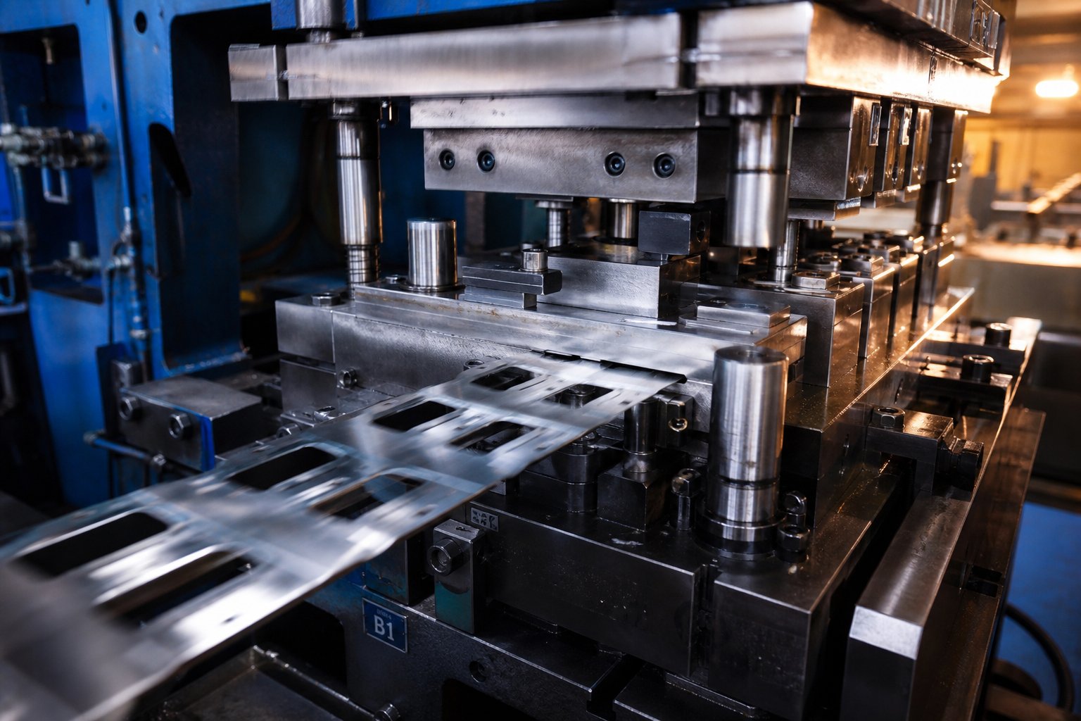
What Makes Progressive Die Metal Stamping Professional Grade
When production engineers specify progressive die metal stamping for a high-volume program, they are not simply choosing a forming method. They are committing to a manufacturing system where strip material advances through sequential stations inside a single stamping die, with each press stroke simultaneously performing distinct operations across every station. The term "progressive" refers to that incremental advancement: the part geometry builds progressively, station by station, until a finished component separates from the carrier strip at the final cutoff.
Professional progressive die metal stamping is a high-volume sheet metal forming process in which a continuous strip feeds through a precision-engineered, multi-station die set, with each press stroke advancing the strip and performing simultaneous operations (piercing, forming, coining, cutoff) to produce finished parts at rates exceeding hundreds of strokes per minute under documented process control.
Defining Progressive Die Metal Stamping at the Professional Level
At a basic level, any shop with a press and a progressive die can stamp parts. Professional-grade operations, however, are defined by what happens around the press. You'll notice the difference in tolerances held to +/-0.05 mm or tighter across millions of cycles, in progressive dies engineered from premium tool steels for multi-million stroke life expectancy, and in real-time process monitoring that catches deviations before they produce scrap. These aren't optional upgrades. They are baseline requirements for automotive, aerospace, and electronics programs where a single defective part can cascade into line shutdowns.
What Separates Professional Operations from General Stamping
The gap between a commodity stamping shop and a professional progressive stamping operation comes down to four pillars:
- Tighter tolerances maintained through precision-ground tooling components and controlled press parameters.
- Engineered die longevity achieved via proper material selection, heat treatment, and coating strategies.
- Documented process control including SPC monitoring, in-die sensors, and traceable inspection records.
- Certified quality systems such as IATF 16949 or ISO 9001 that enforce structured corrective action and continuous improvement.
A professional progressive metal stamping partner treats quality as a cultural foundation rather than an end-of-line checkpoint. Their engineering teams engage during part design, translating geometry into optimized station layouts before any steel is cut. That upstream involvement is what separates a true manufacturing partner from a shop that simply runs parts to print.
Understanding the distinction matters, but the real depth lies in how the process itself unfolds, from the moment strip stock enters the die to the instant a finished part drops into the collection bin.
How the Progressive Die Stamping Process Works Step by Step
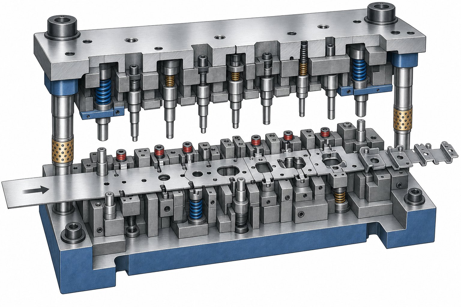
A finished part dropping from a progressive stamping die looks almost effortless, but behind that output is a tightly coordinated sequence of mechanical events happening in fractions of a second. The progressive die stamping process begins well before the press cycles. It starts at the uncoiler, passes through straightening and lubrication systems, and relies on precise feeding and registration mechanics to keep every station aligned across thousands of strokes per hour.
Strip Feeding and Pilot Registration Mechanics
Imagine a continuous ribbon of sheet metal, typically 0.1 mm to 6 mm thick, unwinding from a coil, passing through a straightener to remove coil set, and entering a servo feeder. The feeder advances the strip by a fixed distance called the feed pitch, which equals the spacing between stations in the die. This pitch must be exact. Even a deviation of a few thousandths of an inch compounds across stations and produces out-of-spec parts.
Feeding alone cannot guarantee positioning accuracy at high speed metal stamping rates of 200 to 1,500 strokes per minute. That is where pilot pins come in. Early stations pierce dedicated pilot holes in the strip. As the die closes on subsequent strokes, conical or bullet-shaped pilots enter those holes and nudge the strip into precise alignment before any cutting or forming occurs. According to industry engineering guidance, pilot-to-hole clearance typically runs around 0.0005 to 0.001 inches for precision work, tight enough to correct residual feeder error without distorting the strip.
Feed-roll timing matters just as much as pitch accuracy. The rolls must release the strip before the pilots engage and re-grip only after the die opens. If the feed rolls close too early, particularly near bottom dead center, trapped material between the die and feeder can push the strip forward when pilots exit, creating excessively long progressions that masquerade as feed-length errors.
How Multi-Station Forming Builds Part Geometry
Each station in a progressive stamping die performs one or more specific operations on the strip. Complex three-dimensional geometries are never formed in a single hit. Instead, they develop incrementally, with each station adding features until the part is complete. Think of it as building a component layer by layer, except each layer is a distinct mechanical operation rather than a material deposit.
Here is the typical sequence of station operations in a professional progressive die and stamping setup:
- Pilot hole piercing - Creates registration features used by downstream stations for accurate positioning.
- Blanking and piercing - Cuts internal holes, slots, and partial profiles. Heavy cutting is distributed early to maintain strip stability.
- Lancing and forming - Partially cuts and bends tabs, louvers, or transitional features that prepare the strip for deeper forming.
- Drawing and forming - Creates three-dimensional shapes such as cups, ribs, embosses, or contoured surfaces through controlled material flow.
- Coining and calibration - Compresses material locally to achieve tight dimensional control, flatten surfaces, or sharpen radii beyond what air forming allows.
- Trimming - Removes excess material introduced during forming or eliminates carrier connections around the part perimeter.
- Final cutoff - Separates the completed part from the carrier strip for ejection or collection.
Station sequencing is not arbitrary. Professional die designers place heavy cutting operations early, major forming operations in the middle where the carrier still provides support, and calibration just before cutoff to lock in final dimensions. This approach manages tonnage peaks across the press stroke and prevents strip distortion that would accumulate through later stations.
Press Stroke Sequence and Strip Advance Coordination
The entire progressive stamping process is synchronized to the press stroke cycle. During the downstroke, the upper die descends, pilots engage, and every station performs its operation simultaneously. At bottom dead center, all cutting and forming is complete for that cycle. On the upstroke, the stripper plate holds the strip while punches withdraw, stock lifters raise the strip clear of lower die features, and the feed system advances the material by one pitch.
This relationship between press stroke and strip advance is what makes high speed metal stamping possible. Every cycle, the strip moves forward by exactly one pitch. Every station processes a different portion of the strip at the same instant. The result is one finished part per stroke at the final station, regardless of how many intermediate operations the part requires. A 12-station die running at 400 strokes per minute produces 400 completed parts per minute, with all 12 operations happening in parallel rather than in series.
Strip lift height plays a critical role in this coordination. The strip must rise enough to clear pilots and formed features before advancing, but excessive lift introduces vibration and buckling that limit press speed. Balancing lift height, feed timing, and stroke rate is where the progressive die stamping process moves from textbook theory into applied engineering, and where professional operations distinguish themselves from shops running dies beyond their validated speed windows.
The mechanics of feeding, piloting, and stroke coordination explain how parts move through the die. But the intelligence behind the process lives in the die itself, specifically in the tooling materials, station layout, and design decisions that determine whether a die will hold tolerance for 500,000 strokes or 5 million.
Progressive Die Design and Tooling Fundamentals
A progressive die is only as capable as the decisions embedded in its design. Tooling material, station count, layout sequencing, and force distribution all get locked in before a single stroke runs. Professional progressive die design separates long-lived, repeatable tooling from dies that degrade early and bleed money through unplanned maintenance and scrap.
Tooling Materials and Die Life Expectancy
The steel grade chosen for punches, die inserts, and forming components directly controls how many parts a die can produce before it needs sharpening or replacement. Harder materials resist wear longer, but they also cost more and can be brittle under shock loads. Selecting the right progressive die tooling material means balancing wear resistance against toughness, cost, and the specific demands of the stamped material.
Here is how the most common tooling materials compare in practice:
| Tooling Material | Hardness (HRC) | Wear Resistance | Toughness | Typical Die Life (Strokes) | Best Application |
|---|---|---|---|---|---|
| D2 Tool Steel | 58-62 | High | Moderate | 1-3 million | General piercing and blanking of mild steel and aluminum |
| M2 High-Speed Steel | 60-65 | Very High | Moderate-High | 3-5 million | High-speed piercing, abrasive materials like stainless steel |
| Carbide (Tungsten Carbide) | 70-75+ | Excellent | Low | 5-20+ million | High-volume programs requiring maximum die life with minimal regrind |
D2 covers a wide range of progressive tool and die applications at a reasonable cost. M2 steps in when press speeds increase or when stamping harder alloys that chew through lower-grade steels. Carbide inserts push die life into the tens of millions, but they require careful press alignment and shock-free operation because carbide fractures rather than deforms under excessive off-center loads.
Professional die builders also apply surface treatments like TiN or TiCN coatings to reduce friction, delay galling on stainless steel parts, and extend intervals between sharpening cycles.
Station Layout Planning for Complex Parts
Translating a finished part geometry into an optimized station layout is where stamping die design moves from mechanical engineering into applied problem-solving. Experienced manufacturers like YICHEN approach this phase by mapping every feature on the part, identifying forming sequences that minimize material distortion, and distributing cutting and forming forces evenly across the press stroke.
Station layout planning follows a structured methodology:
- Identify all piercing, forming, and trimming operations required by part geometry.
- Sequence operations so heavy cutting happens early on flat material and forming occurs midstream while the carrier still provides stability.
- Group compatible operations into shared stations where tonnage and spatial clearance allow.
- Insert idle (blind) stations between heavy forming stages to allow strip relaxation and provide room for future design modifications.
- Validate that total tonnage across all active stations remains within press capacity with a safety margin of 15-20%.
Poorly planned layouts create force spikes that deflect the press ram, accelerate wear on one side of the die, and introduce dimensional variation. A well-sequenced progressive stamping die design distributes loads symmetrically and keeps the strip tracking straight through every station.
Balancing Die Complexity with Production Goals
More stations mean more capability, but they also mean a wider die, a larger press bed, and higher tooling cost. Professional die designers weigh station count against strip width, which drives material cost per part, and against the press tonnage required, which limits machine options on the production floor.
A 16-station die that fits a 200-ton press is often a better economic choice than a 22-station die requiring a 400-ton press, even if the latter consolidates more operations. The decision comes down to annual volume, available press capacity, and total cost of ownership over the die's expected life.
This is where progressive stamping die design becomes a collaborative exercise between part designers, die engineers, and production planners. YICHEN's progressive stamping die development process, for example, focuses on engineering dies that hit repeatability targets while fitting within scalable production infrastructure, giving procurement teams a clear path from prototype validation to mass production.
Tooling material and station layout lock in the die's performance ceiling. But even the most precisely engineered die cannot compensate for poor material selection or inefficient strip layout upstream, which is where carrier design and nesting strategy take over.
Material Selection and Strip Layout Optimization
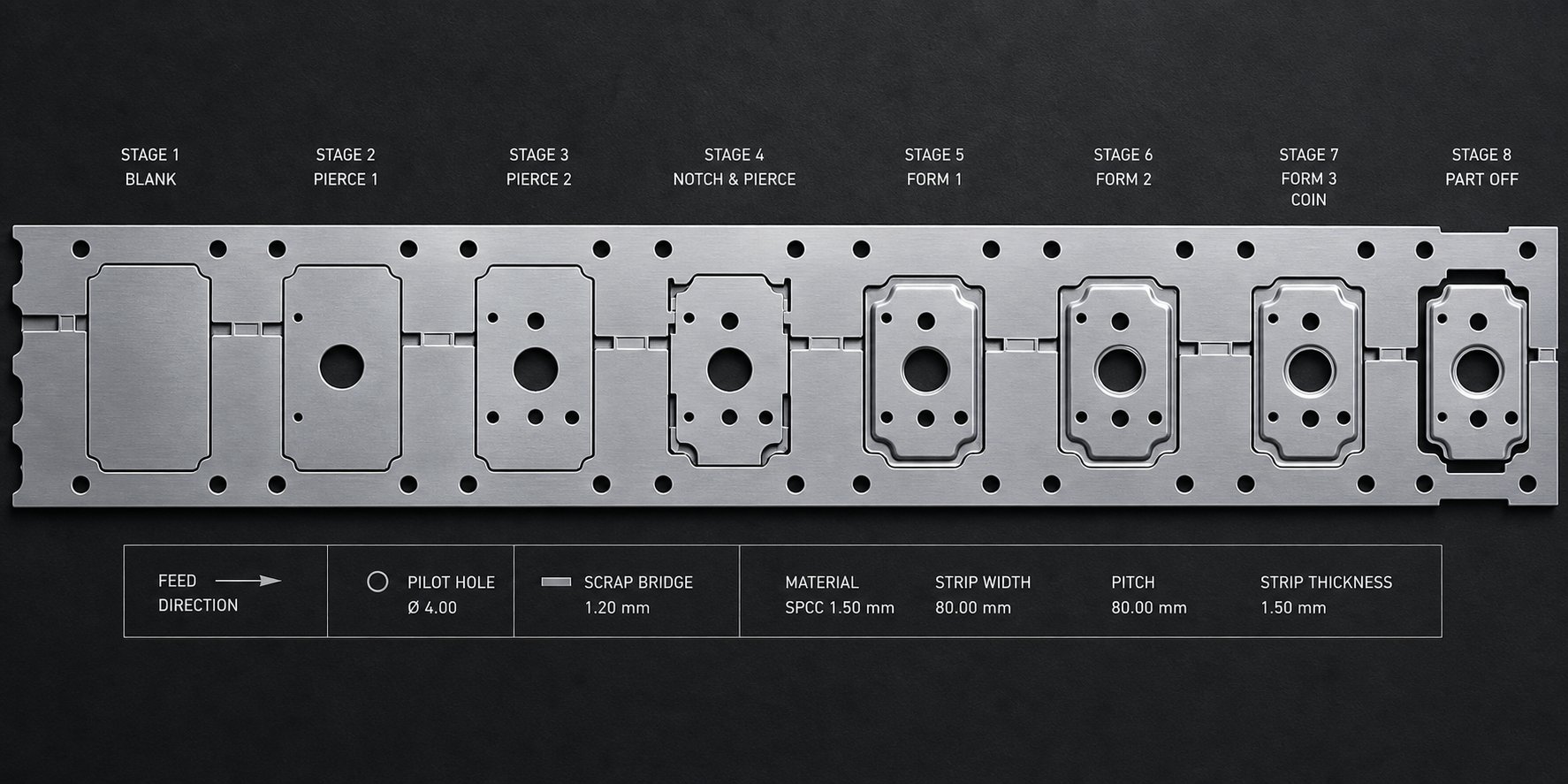
Raw material typically accounts for 40-60% of the total cost of a stamped part. That means the decisions made during strip layout design and material selection have more influence on per-part economics than almost any other factor in the process. A well-optimized layout squeezes maximum parts from every coil, while the right material choice ensures those parts form cleanly without cracking, wrinkling, or excessive springback.
Carrier Strip Design and Nesting Optimization
The carrier strip is the skeletal backbone that holds partially formed parts together as they advance through the die. It is not the finished product, so every square millimeter of carrier material becomes scrap. Designing it as thin and narrow as possible, while still maintaining enough strength to push the strip through all stations without buckling, is a balancing act that directly impacts material utilization.
Two carrier types serve different progressive stamping applications:
- Solid carriers work for basic cutting and bending operations where the strip stays flat throughout the entire press stroke. They offer maximum rigidity but cannot accommodate vertical part movement between stations.
- Stretch web carriers incorporate strategic cuts or loops that allow the carrier to flex vertically and horizontally. These are essential for parts requiring deep drawing, embossing, or multi-step forming where material must flow inward without distorting the pitch between parts.
A poorly designed carrier can cause total tool failure. If the attachment web is too narrow, it tears during forming. If it is too rigid for a deep-draw application, it locks the strip pitch and causes misregistration downstream. Professional die engineers use simulation software to predict carrier deformation and validate that the flex web provides enough length of line to accommodate vertical travel without thinning past the material's fracture limit.
Nesting strategy determines how parts are oriented and positioned on the strip to minimize waste. For progressive stamping materials, common approaches include:
- Single-row layouts - Simple and predictable, best for symmetrical parts but often lower material utilization.
- Angular or rotated nesting - Tilts parts at an angle to fit closer together, like puzzle pieces. This can significantly reduce strip width for irregularly shaped geometries.
- Multi-row layouts - Stamps two or more parts side by side per press stroke, increasing throughput and improving utilization when part dimensions allow.
The industry benchmark for material utilization in progressive die operations is at least 75%. Reaching that target requires careful optimization of bridge width, the small sections of material left between adjacent parts and between parts and the strip edge. A common rule sets minimum bridge thickness at 1.25 to 1.5 times the material thickness. For a 1.5 mm strip, that translates to a bridge of roughly 1.9 to 2.25 mm, just enough to prevent scrap from twisting and jamming the die.
Strip width optimization ties directly into per-part cost. A narrower strip means less raw material consumed per cycle, but it also means tighter margins on carrier strength and edge stability. The feed pitch, which is the distance the strip advances per stroke, combines with strip width to define the rectangular area of material consumed per part. Reducing either dimension while maintaining structural integrity and formability lowers material cost proportionally.
Metal Types and Thickness Ranges for Progressive Stamping
Not every metal runs well in a progressive die. The process demands materials that can withstand repeated bending, piercing, and forming across multiple stations without cracking or work-hardening to the point of fracture. Formability, surface hardness, and springback behavior all influence whether a given alloy is a good candidate for high-speed progressive metal stamping.
Here is how the most common progressive stamping materials compare across practical attributes:
| Material Category | Formability Rating | Typical Thickness Range | Common Applications | Special Tooling Considerations |
|---|---|---|---|---|
| Low-Carbon Steel (C1008-C1010) | Excellent | 0.2 - 4.0 mm | Brackets, chassis components, structural supports, electrical enclosures | Standard D2 tooling performs well; minimal galling concern |
| Stainless Steel (301, 304, 316) | Moderate-Good | 0.1 - 3.0 mm | Medical devices, food equipment, electronic shielding, corrosion-resistant hardware | High work-hardening rate demands M2 or carbide tooling; TiN coatings reduce galling |
| Copper Alloys (C110, C194, C260 Brass) | Good-Excellent | 0.1 - 2.5 mm | Electrical terminals, connectors, heat sinks, RF shielding | Soft material can generate burr buildup on punches; frequent slug clearing needed |
| Brass (C260, C270) | Excellent | 0.1 - 2.0 mm | Plumbing fittings, decorative hardware, electrical contacts, instrument components | Excellent formability with low springback; standard tooling adequate for most applications |
| Aluminum Alloys (1100, 3003, 5052) | Good-Excellent | 0.2 - 3.5 mm | Heat sinks, automotive panels, electronic housings, aerospace brackets | Adhesive buildup on tooling requires polished die surfaces or specialized coatings; softer alloys need wider punch-to-die clearance |
Carbon steel progressive stamping dominates high-volume structural programs because the material is inexpensive, forms predictably, and runs at high press speeds without special lubricants. Grades like C1008 and C1010 offer the ductility needed for complex bends and draws while remaining stiff enough to maintain carrier integrity through multi-station dies.
Copper progressive stamping and brass progressive stamping are standard in the electrical and electronics sectors. These alloys combine excellent conductivity with good formability, making them ideal for terminals, bus bars, and spring contacts. Brass in particular offers very low springback, which simplifies tooling and reduces station count for parts with tight angular tolerances.
Aluminum progressive stamping presents unique challenges. The metal's softness causes it to adhere to tooling surfaces, building up deposits that create surface defects on finished parts. Professional operations counter this with highly polished punch and die surfaces, specialized lubricants, and sometimes chromium or DLC coatings on forming components. Despite these considerations, aluminum remains the go-to choice for lightweight components in automotive and electronics applications where weight savings justify the additional tooling attention.
Stainless steel sits at the demanding end of progressive stamping materials. Its high work-hardening rate means material strength increases significantly during forming, which accelerates punch wear and increases stripping forces. Successful stainless programs rely on premium tooling steels (M2 or carbide), precise punch-to-die clearances, and aggressive lubrication strategies to manage heat generation at high stroke rates.
Choosing the right material is half the equation. The other half is designing parts that respect the physical limits of progressive forming, where feature placement, bend radii, and dimensional proportions determine whether a die runs trouble-free or fights the geometry at every station.
Design for Manufacturability Guidelines in Progressive Stamping
Every feature you draw on a part model eventually becomes a station in a die, a punch that wears, or a forming operation that adds tonnage to the press. Design for manufacturability in progressive stamping means engineering your part geometry so the die can produce it reliably at speed without requiring exotic tooling, excessive stations, or constant maintenance interventions. The rules below translate material science and metal stamping die design experience into actionable constraints you can apply at the CAD stage, before tooling cost estimates even begin.
Critical Dimensional Rules for Progressive Die Parts
Holes, slots, and cutouts are among the first features formed in a progressive stamping tool, typically at early piercing stations. Their size and placement relative to material thickness determine whether punches survive millions of cycles or fracture prematurely. Violate minimum sizing rules, and you force the use of fragile, undersized stamping die components that drive up maintenance cost and increase scrap rates.
Here are the core dimensional rules that professional die engineers apply when evaluating part feasibility:
- Minimum hole diameter: At least 1.0x material thickness for ductile metals like low-carbon steel and brass. For high-tensile materials such as stainless steel, increase to 2.0x material thickness to prevent punch breakage.
- Minimum slot width: At least 1.5x material thickness. Narrower slots require specialized high-speed steel or carbide punches, increasing tooling cost significantly.
- Minimum distance between holes: At least 2.0x material thickness edge-to-edge. Closer spacing causes the web between features to deform or tear during piercing.
- Minimum distance from hole to edge: At least 2.0x material thickness. Features closer to the part edge create outward bulging that distorts the blank profile.
- Minimum distance from hole to bend line: At least 2.0x material thickness plus the bend radius for features under 2.5 mm diameter. For larger features, increase to 2.5x material thickness plus the bend radius to prevent stretching or distortion during forming.
- Minimum flange height: At least 2.5x material thickness plus the bend radius. Shorter flanges lack enough material for the punch to grip during bending, producing inconsistent angles.
- Minimum tab and notch width: At least 1.5x material thickness to avoid excessive force concentration on narrow punches.
- Internal corner radii on cutouts: At least 0.5x material thickness. Sharp internal corners act as stress risers in the die and the part, reducing die life and creating crack initiation points.
These values represent practical minimums, not targets. Designing above these thresholds gives the stage tooling more breathing room, extends sharpening intervals, and reduces the probability of punch failure during long production runs. When your part geometry pushes against several of these limits simultaneously, expect the die builder to add stations or recommend geometry modifications.
Bend Radius and Grain Direction Considerations
Bending operations typically occur at mid-to-late stations in a progressive die, after piercing and before final cutoff. The internal bend radius you specify controls whether the material flows smoothly around the punch nose or cracks on the outer fiber. Too tight a radius on the wrong material in the wrong orientation, and the part splits at the bend line.
A safe starting point for internal bend radius is 1.0x material thickness for ductile alloys like low-carbon steel and aluminum 3003. For higher-strength materials such as stainless steel 304 or spring-temper copper, increase that minimum to 1.5x material thickness or higher depending on the alloy's elongation properties. Going below 1.0x thickness on any material introduces cracking risk that worsens as the die wears and punch radii sharpen over time.
Grain direction is equally critical. Sheet metal has a rolling direction established during mill processing, and its ductility varies depending on whether you bend with or against that grain. Bends made perpendicular to the grain direction are stronger and far less prone to cracking than bends made parallel to it. For parts requiring bends in multiple orientations, orient the blank on the strip so the most critical or tightest bend runs perpendicular to the grain.
When a part demands bends in both directions, angling the blank at 45 degrees to the rolling direction offers a compromise that distributes strain more evenly across both bend axes. Keep in mind that angled nesting increases strip width and material consumption, so there is a cost tradeoff. Call out grain direction requirements on your engineering drawing, especially for parts in hardened or high-strength alloys where cracking risk is elevated.
Springback, the tendency of metal to partially recover its original shape after bending, also varies with grain orientation and material strength. Professional sheet metal stamping die programs compensate for springback by over-bending the punch angle or adding a coining station that permanently sets the bend. Specifying the allowed angular tolerance on your drawing (typically +/- 1 degree for standard bends) helps the die designer determine whether simple air bending suffices or a dedicated calibration station is required.
Feature Placement Rules That Reduce Die Complexity
Every feature on your part must be formed by a specific stamping die component: a punch, a forming insert, a cam mechanism, or a combination. Features that are too close together, too deep relative to their width, or positioned in mechanically awkward locations force the die designer to add stations, use fragile tooling, or introduce secondary operations outside the die. All of these add cost.
A few placement principles keep die complexity in check:
- Avoid features directly adjacent to bends. Holes or embosses placed within 2x material thickness of a bend line will distort during forming. Either add relief cuts to isolate the feature or relocate it further from the bend.
- Keep formed features unidirectional when possible. Parts with bends in both directions (up and down relative to the strip plane) require stock lifters, additional clearance for strip travel, and sometimes cam-driven tooling. Designing all forms in one direction simplifies the progressive stamping tool and allows higher press speeds.
- Minimize the number of distinct forming depths. Each unique draw depth or emboss height may need its own station. Standardizing depths across multiple features lets the die designer combine operations into fewer stations.
- Add bend relief notches at free edges. When a bend terminates at an edge rather than running across a continuous surface, material bunches and tears at the transition. A relief notch at least 2x material thickness wide and extending the length of the bend radius plus the material thickness prevents tearing and eliminates burr-prone witness marks.
- Avoid very narrow projections or deep narrow slots. Features with aspect ratios exceeding 4:1 (length to width) create thin, fragile die punches that wear rapidly and are expensive to replace.
- Consolidate tight-tolerance features into the same station. When two dimensions must be held in precise relationship to each other, design them so they can be cut or formed in a single press hit. Splitting related features across stations introduces cumulative positioning error from strip registration tolerances.
Sounds complex? It can be, but the underlying logic is straightforward: every rule above protects either the die (by avoiding fragile tooling) or the part (by preventing deformation, cracking, or tolerance loss). Applying these guidelines during initial design eliminates costly revision loops once the die build is underway.
Even the best-designed geometry, however, only stays within spec if the production process catches deviations in real time. That reality shifts focus from part design toward the quality control systems that monitor every stroke, detect anomalies, and prevent defective parts from reaching downstream assembly.
Quality Control and Defect Prevention in Progressive Die Operations
A progressive die running at 400 strokes per minute produces nearly seven parts every second. At that speed, a human operator cannot visually inspect every piece. Quality control in high precision metal stamping relies instead on automated sensing systems embedded directly in the tooling, statistical methods that flag process drift before it reaches reject limits, and structured inspection protocols that validate capability at the start of every production run.
In-Die Sensing and Real-Time Monitoring
In-die sensing began as crash prevention, stopping the press before a misfed strip or pulled slug destroyed expensive tooling. Professional precision die stamping operations have since evolved this technology into a multi-tiered quality system that detects defects, halts production on faults, and in closed-loop configurations, automatically adjusts forming stations between strokes to keep parts within tolerance.
The most common sensor categories used inside a metal stamping die include:
- Stripper level sensors - Proximity sensors mounted at the corners of the lower die monitor the stripper plate's closing depth every stroke. If a pulled slug, broken punch tip, or debris sits on the strip, the plate cannot reach its full travel depth. The press stops within one stroke of detecting the irregularity, typically calibrated to detect deviations as small as 1.5x strip thickness.
- Misfeed detection sensors - Positioned to confirm that the strip has advanced the correct pitch before the die closes. If the feed system short-feeds or double-feeds, the sensor triggers a fault before pilots attempt to register improperly positioned material.
- Punch presence sensors - Optical or proximity sensors that verify small, breakage-prone punches remain intact. A missing punch tip means missing holes in the part, a defect that may not cause a crash but will produce nonconforming progressive die stampings that escape downstream if undetected.
- In-die load cells - Miniature force sensors built into specific punch holders or forming stations. They detect force changes that indicate dulling, chipping, or material thickness variation, particularly useful in coining or scoring operations where force directly correlates to part quality.
- Analog bend-angle sensors - Measure formed angles within fractions of a degree. In closed-loop systems, servomotors adjust forming wedges between strokes to correct angular drift automatically, preventing bad parts rather than merely detecting them.
A dedicated sensor technician, typically an experienced toolmaker, manages sensor selection, installation, and calibration. Professional shops invest in sensor labs where technicians can map sensor fields across all three axes, plotting effective ranges before the die is even built. This upfront validation saves significant press time during tryout.
SPC Methods for Stamped Part Consistency
In-die sensors catch catastrophic events and gross defects. Statistical process control (SPC) catches the subtler, slower shifts that creep in over thousands of strokes as punches wear, material properties vary coil-to-coil, or press conditions drift with temperature changes.
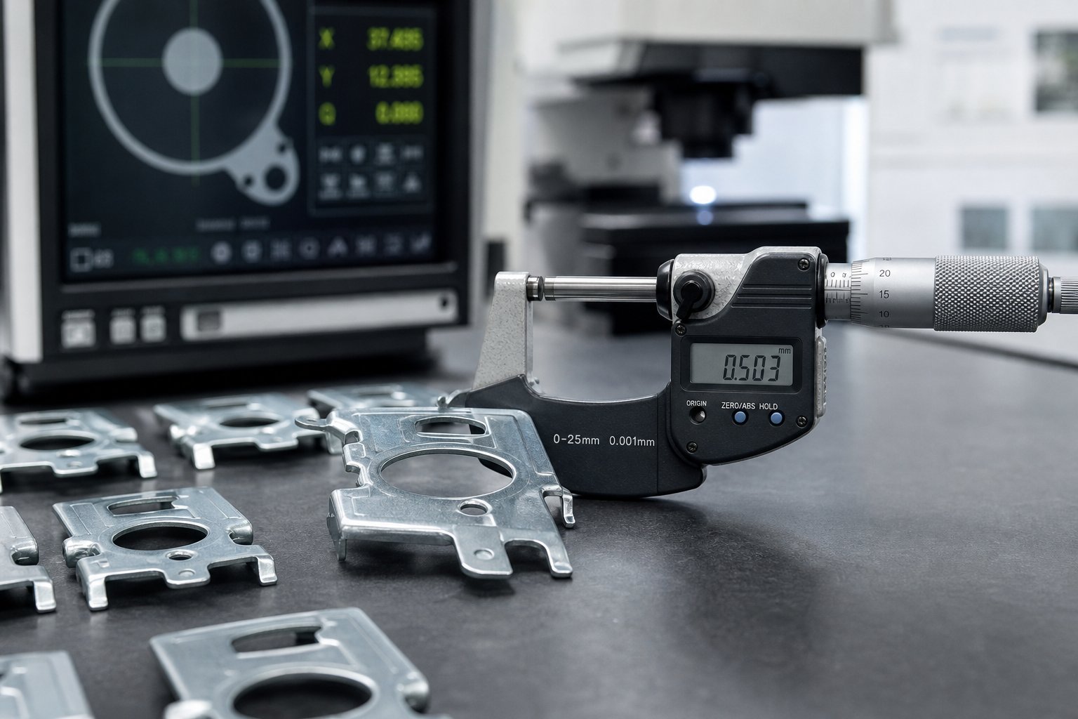
Professional precision die and stamping operations apply SPC to critical dimensions by sampling parts at defined intervals, measuring them on calibrated instruments (CMMs, optical comparators, micrometers), and plotting the results on control charts. The key metrics are Cp and Cpk:
- Cp measures whether the process spread fits within the tolerance window, regardless of centering. A Cp of 1.33 means the process uses 75% of the available tolerance band.
- Cpk measures how well the process is centered within that window. Most automotive and electronics programs require a minimum Cpk of 1.33, with aerospace and medical applications often demanding 1.67 or higher.
When Cpk drops below target, the root cause must be identified. Is the mean shifting (tool wear moving the dimension in one direction)? Or is the spread increasing (variation growing due to material inconsistency or loose press gibs)? Control charts reveal the pattern, and corrective action follows: regrinding a punch to restore edge geometry, adjusting blank holder pressure, or switching to a tighter-tolerance coil lot.
First-article inspection (FAI) anchors the entire SPC system. Before full production launches, one or more parts produced with standard tooling, materials, and press parameters are fully measured against every drawing dimension. The resulting FAI report validates that the process is capable and stable before volume production begins. FAI is repeated after die maintenance, material changes, press changes, or any process modification that could affect dimensional output.
Common Defects and Root Cause Analysis
Even with sensors and SPC in place, defects still occur. The difference in professional operations is how quickly they are identified and how systematically the root cause is traced. Experienced stamping engineers recognize that most defects have multiple potential causes, and the fix requires understanding the interaction between material, tooling, and press variables rather than simply blaming the die.
| Defect | Probable Causes | Corrective Actions |
|---|---|---|
| Excessive burr on cut edges | Worn or chipped punch edges; excessive punch-to-die clearance; dull cutting steels | Sharpen punches and dies; verify and restore proper clearance (typically 5-10% of material thickness per side); replace worn inserts |
| Splitting at bend lines | Bend radius too tight for material; bending parallel to grain direction; material exceeds specified hardness | Increase bend radius; rotate blank orientation relative to grain; verify incoming material properties against spec |
| Wrinkling in formed areas | Insufficient blank holder pressure; excessive material in compression zone; improper draw bead geometry | Increase hold-down force; adjust blank size or shape; modify draw bead profile to control material flow |
| Misregistration (features out of location) | Feed length error; worn or undersized pilot pins; improper feed release timing; pilot hole distortion from upstream forming | Recalibrate feed length; replace worn pilots; adjust feed release timing so material is free before pilots engage; relocate pilot holes away from forming zones |
| Surface dents or marks | Pulled slugs trapped on strip; debris in die; slug buildup in die cavities; rough tooling surfaces | Improve slug retention (add vacuum or positive knockout); increase die cleaning frequency; polish forming surfaces; add stripper-level sensors to detect trapped debris |
| Dimensional drift over run | Progressive punch wear; thermal expansion of die components; material property variation within coil | Establish sharpening intervals based on SPC trends; allow thermal stabilization before measuring production parts; tighten incoming material specifications |
| Springback exceeding tolerance | Insufficient over-bend compensation; material yield strength higher than nominal; worn forming punch radius | Increase over-bend angle; add coining or restrike station; verify material certifications; restore punch nose radius to print |
The pattern across all these defects is clear: professional operations prevent them through controlled inputs (sharp tooling, correct clearances, verified materials) rather than sorting them out after the fact. In-die sensing catches the acute failures. SPC catches the gradual drift. And FAI confirms the baseline before volume production ever starts.
Preventing defects protects quality, but it also protects economics. Every scrap part represents wasted material, lost press time, and potential downstream disruption. That connection between quality discipline and production cost is exactly why understanding the financial structure of progressive die operations matters as much as understanding the technical process itself.
Cost Drivers and Production Volume Economics
Tooling investment is the single largest financial decision in any die stamping program. A progressive die can cost anywhere from $15,000 for a straightforward bracket tool to well over $100,000 for a complex multi-station die with carbide inserts and in-die sensing. That range is enormous, and understanding what drives it helps engineers and procurement teams make informed buy decisions rather than simply chasing the lowest quote.
What Drives Progressive Die Tooling Cost
When you receive a tooling estimate that seems high, or one that seems suspiciously low, trace the number back to the variables that actually determine die price. As industry tooling expert Art Hedrick notes, cost differences of more than 50% between shops quoting the same part are common, and the divergence almost always traces back to differences in how each shop processes the part rather than differences in hourly rates alone.
Here are the primary factors that scale progressive die cost up or down:
- Number of stations: Each station adds punches, die inserts, strippers, and precision-ground components. A 10-station die might cost 40-60% more than a 6-station die for the same part simply because of the additional machined components and assembly labor.
- Die material selection: Specifying carbide inserts instead of D2 tool steel at critical wear points can add 20-30% to tooling cost, but extends die life by 5-10x. The decision depends on total volume projections.
- Part complexity and tolerances: Parts with deep draws, multiple bend directions, or tight positional tolerances (below +/-0.05 mm) require more stations, tighter machining on die components, and longer tryout cycles. Tight-tolerance parts increase tooling cost because they demand precision ground and jig-bored components rather than standard wire-EDM profiles.
- Strip width and press tonnage: A wider die demands a larger die set, heavier shoe plates, and a press with a bigger bed. These factors increase both material cost and the hourly machining rates charged during die build.
- Secondary operations eliminated: Dies that incorporate tapping, hardware insertion, or in-die measurement stations cost more upfront but remove downstream labor. The business case depends on whether the secondary cost savings exceed the incremental tooling investment over the program's lifetime.
- Vendor capabilities and location: Labor rates for die designers and toolmakers vary by region. More importantly, a shop experienced in your specific part category can process it in fewer stations because they draw on past solutions rather than engineering from scratch.
The process used to make the part, meaning the number of stations and their sequence, is the largest single factor driving cost variance between quotes. One shop might quote a 10-station progressive die with a 5-inch pitch while another quotes 15 stations with a wider pitch. That difference in processing methodology produces a significant price gap even when both shops charge similar hourly rates.
Volume Thresholds and Method Comparison Economics
Progressive dies carry high upfront investment but deliver the lowest per-part cost at volume. The question every production engineer faces is: at what annual quantity does a progressive die become the right economic choice over simpler alternatives?
The answer depends on part complexity, but general volume thresholds based on industry practice look like this:
- Single-station dies: Best for annual volumes under 10,000 parts. Low tooling investment ($3,000-$15,000), but each operation requires a separate press hit, separate handling, and often manual loading. Per-part cost remains high due to labor and cycle time.
- Compound die stamping: Suitable for 5,000 to 75,000 parts annually when the geometry is relatively flat (piercing and blanking in a single plane). Moderate tooling cost ($8,000-$30,000) with good per-part economics for simple shapes, but limited to parts that do not require forming or bending.
- Transfer dies: Ideal for 25,000 to 500,000 parts annually, especially larger or deeper-drawn components that cannot maintain a carrier strip. Tooling cost ($30,000-$150,000+) is comparable to progressive dies, but cycle rates are slower because mechanical transfer systems move individual blanks between stations rather than advancing a continuous strip.
- Progressive dies: Most economical for long run progressive stamping programs exceeding 50,000 parts annually, with the cost advantage growing sharply above 100,000 units. Tooling investment ($15,000-$100,000+) is high, but cycle rates of 200-1,500 strokes per minute drive per-part cost to fractions of a cent for labor and machine time.
The crossover point where progressive tooling wins is not fixed. For a simple bracket that can run at 600 SPM in a 6-station die, the breakeven against single-station methods might occur at 30,000 parts. For a complex connector requiring 18 stations and carbide tooling, the breakeven might not arrive until 150,000 units.
What matters is total cost of ownership, not just the die price on the purchase order. A $40,000 progressive die producing 500,000 parts over five years adds just $0.08 per part in amortized tooling cost. That same part run on a $12,000 single-station die at 10 parts per minute instead of 400 would cost multiples more in press time and labor, even though the die itself was cheaper.
Smart procurement teams evaluate dies and stamping programs on amortized tooling cost plus piece price, not on tooling cost alone. They also factor in maintenance reserves, typically 2-5% of tooling cost annually, which cover sharpening, component replacement, and eventual refurbishment. A well-built die producing high volume stampings over several million cycles often returns its investment many times over when the full cost picture is calculated.
Per-part economics improve with volume, but only if the die stays in production-ready condition across those millions of strokes. That reality makes maintenance strategy not just a technical concern but a financial one, directly tied to the cost model that justified the tooling investment in the first place.
Progressive Die Maintenance and Lifecycle Management
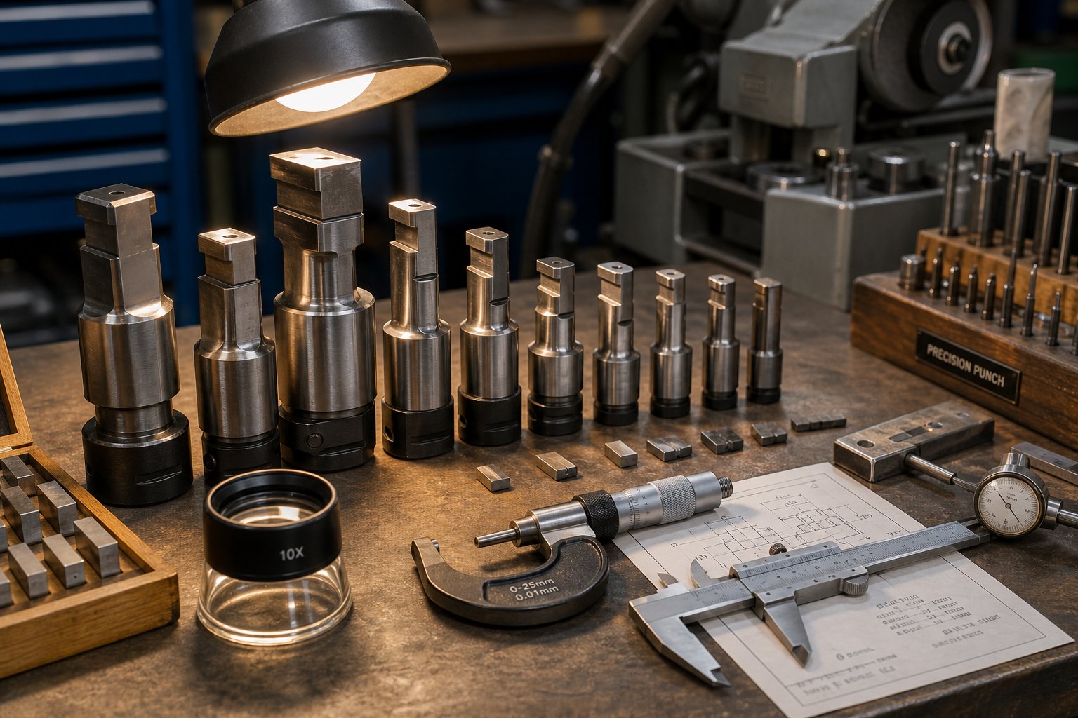
A progressive die that cost $60,000 to build can deliver $0.08-per-part economics across millions of cycles, but only if its cutting edges stay sharp, its forming surfaces stay polished, and its alignment mechanisms stay within spec. Stamping die maintenance is not a discretionary activity you schedule when parts start looking bad. It is a planned, data-driven discipline that protects both quality and throughput from the first production run to the last.
Preventive Maintenance Schedules and Sharpening Intervals
Professional operations establish PM intervals based on stroke counts rather than calendar dates. A stamping die set running 300,000 parts per month accumulates wear at a fundamentally different rate than the same tool running 30,000 parts quarterly. Stroke-based scheduling ensures every service happens at the right time regardless of production frequency.
As stamping expert Thomas Vacca emphasizes, best-in-class maintenance starts with identifying every area of the tool that degrades over time, then documenting a consistent procedure for servicing each one. The goal is predictability: consistent hits per service interval, consistent part quality off the tool, and minimal unplanned downtime.
Key maintenance activities and their typical frequency triggers include:
- Punch and die sharpening: Every 50,000-150,000 strokes depending on material hardness and stamping die steel grade. Burr height on parts (typically exceeding 10% of material thickness) signals the interval has been reached. A standard regrind removes 0.05-0.10 mm per service.
- Pilot pin inspection and replacement: Every 100,000-250,000 strokes. Worn pilots allow strip misregistration that compounds across stations. Replace when diameter measures 0.01 mm or more below nominal.
- Spring inspection and replacement: Every 200,000-500,000 strokes, or immediately when free-length measurements fall below 90% of original. Fatigued springs reduce stripping force and increase slug-pulling risk.
- Form punch and die insert inspection: Every 100,000-300,000 strokes. Polished forming surfaces develop micro-scratches that transfer to parts. Visual inspection under magnification reveals when repolishing or replacement is needed.
- Lifter and guide component check: Every PM cycle. Worn lifters cause uneven strip elevation, leading to feed errors and pilot damage at high speed.
- Full die alignment verification: Every 500,000-1,000,000 strokes, or after any press crash event. Checking die shoe parallelism, guide pin clearance, and shut height confirms the stamping die set maintains its original precision.
How much material you remove during sharpening matters as much as when you sharpen. Vacca stresses that documented, consistent procedures are essential. If one technician removes 0.05 mm and another removes 0.15 mm, sharpening life varies wildly between services, making hits-per-interval unpredictable and complicating component replacement planning.
Component Wear Patterns and Replacement Planning
Not every component in a progressive die wears at the same rate. Cutting stations degrade faster than forming stations because shear forces concentrate on narrow edge bands. Progressive carbide stamping dies extend these intervals dramatically, but even carbide tooling eventually needs service, particularly at piercing stations where abrasive materials like stainless steel accelerate edge breakdown.
Wear patterns in steel stamping dies follow predictable hierarchies:
- Small piercing punches wear fastest due to high shear stress concentrated on minimal cross-sectional area.
- Blanking punches and die buttons wear next, driven by total cutting perimeter and material thickness.
- Forming punches degrade more slowly but show surface roughening that transfers to parts as cosmetic defects.
- Guide pins and bushings wear gradually and often go unnoticed until alignment-related quality issues appear.
Professional operations maintain spare components for high-wear items ready to install during scheduled PM windows. This approach eliminates delays waiting for replacement parts and keeps die downtime within planned maintenance windows. Saving the last part and end strip from each production run, as experienced toolmakers recommend, gives the next service technician direct visual evidence of tool condition at shutdown.
Tracking cumulative grind loss is equally critical. Every regrind shortens a punch. Once a punch has been sharpened past its allowable stack-up (typically 2-3 mm total removal across all services), it must be replaced entirely. Logging each grind amount against maximum allowable loss tells you exactly when to order replacement components, turning reactive surprises into planned procurement events.
The economics are straightforward: a well-maintained die delivering consistent quality across its rated life costs far less per part than a neglected die that produces scrap, forces unplanned press stops, and requires emergency repairs at premium labor rates. Stamping die maintenance is not overhead. It is a direct contributor to the per-part cost model that justified the tooling investment.
Maintenance keeps existing tooling productive, but it cannot tell you whether the shop behind that tooling has the engineering depth, press capacity, and quality infrastructure to support your next program. That evaluation requires a different set of criteria entirely.
Selecting a Professional Progressive Die Stamping Partner
A well-maintained die is only as reliable as the operation running it. The shop's engineering depth, press infrastructure, and quality culture determine whether your program delivers consistent parts at target cost or becomes a recurring source of delays and rejects. Evaluating progressive die manufacturers requires looking past marketing claims and into the technical specifics that separate capable partners from commodity vendors.
Key Qualification Criteria for Die Stamping Partners
When you request quotes from progressive die stampings suppliers, every response will claim tight tolerances and quality commitment. The difference shows up in the details. Use the following checklist to objectively compare potential providers of progressive die stamping services:
- In-house die design and simulation capability: Does the supplier engineer their own tooling using CAD/CAM and FEA simulation, or do they outsource die design? In-house design means faster iteration, tighter integration between design intent and production reality, and a single point of accountability when issues arise.
- Press tonnage range and bed size: Confirm they operate presses that match your part's tonnage and strip width requirements with at least a 20% capacity margin. A supplier running your die at 90% of press capacity has no headroom for process variation.
- Material handling systems: Coil handling (decoilers, straighteners, servo feeders) must be rated for your material type, thickness, and coil weight. Ask whether they run servo feeds or mechanical rolls, and whether they have the lubrication systems appropriate for your alloy.
- Quality certifications: ISO 9001 is a baseline. Automotive programs typically require IATF 16949. Medical and aerospace applications demand additional traceability and validation protocols. Certifications confirm that systems are documented and audited, not just claimed.
- Prototyping and pilot run support: Can they produce sample parts for validation before committing to full production tooling? Suppliers offering T0/T1 tryout with CPK validation during pilot runs demonstrate engineering rigor that reduces risk during production launch.
- Production scalability: Evaluate whether they can scale from pilot quantities to millions of parts annually without switching presses, altering die setup, or subcontracting overflow. Scalability gaps create quality discontinuities.
- Maintenance infrastructure: Ask about their tool room capabilities, sharpening equipment, spare component inventory practices, and die history documentation. A supplier that tracks cumulative grind loss and maintains spares for high-wear items will keep your die in production-ready condition.
- Technical communication: How do they present proposals? A detailed quote breaking down station count, tooling materials, expected die life, and recommended maintenance intervals signals engineering depth. A lump-sum price with minimal explanation signals a commodity approach.
Evaluating Engineering Depth and Production Scalability
The most revealing indicator of a progressive die manufacturer's capability is how they respond to your part geometry during the quoting phase. Experienced metal stamping die manufacturers like YICHEN will review your part drawing, identify forming challenges, suggest DFM improvements, and present a strip layout concept before finalizing the quote. They translate part geometry into optimized station sequences rather than simply pricing based on part envelope dimensions.
Compare that to a commodity shop that returns a price without asking questions about annual volume, tolerance priorities, or material grade. The absence of technical dialogue during quoting almost always predicts problems during production.
When evaluating progressive die metal stamping services, ask these pointed questions during the qualification process:
- How many stations do you recommend, and why that number rather than fewer or more?
- What tooling materials will you use at each station, and what die life do you guarantee?
- What is your typical Cpk at production launch, and how do you maintain it across the run?
- Can you provide references from programs with similar part complexity and volume?
Suppliers who answer these questions with specifics, citing steel grades, stroke-count guarantees, and SPC methodology, are operating at a professional level. YICHEN's progressive stamping die programs, for example, focus specifically on high-volume parts requiring efficient multi-station forming and tight repeatability, with tooling engineered for scalable mass production from the outset.
The right partner does not just build a die and ship it. They engage as a technical resource through design, validation, launch, and ongoing production support. That collaborative model, where stamping die manufacturers invest engineering time upfront to prevent problems downstream, delivers the lowest total cost of ownership and the most predictable production outcomes over the life of your program.
Frequently Asked Questions About Progressive Die Metal Stamping
1. What is the difference between progressive die stamping and transfer die stamping?
Progressive die stamping advances a continuous strip through multiple stations within a single die, producing one finished part per press stroke at speeds up to 1,500 strokes per minute. Transfer die stamping uses mechanical systems to move individual blanks between separate die stations, making it better suited for larger or deeper-drawn parts that cannot maintain a carrier strip. Progressive dies excel at volumes above 50,000 parts annually with smaller geometries, while transfer dies serve mid-volume programs (25,000-500,000 parts) involving complex three-dimensional forming that exceeds carrier strip limitations.
2. How many parts can a progressive die produce before it needs maintenance?
Maintenance intervals depend on tooling material and the stamped metal type. D2 tool steel punches typically require sharpening every 50,000-150,000 strokes, M2 high-speed steel extends that to higher ranges, and carbide inserts can run 5-20 million strokes before service. Burr height exceeding 10% of material thickness is the primary signal that sharpening is due. Professional operations schedule all preventive maintenance by stroke count rather than calendar dates, tracking cumulative grind loss to predict component replacement timing accurately.
3. What materials work best for progressive die stamping?
Low-carbon steel (C1008-C1010) is the most widely used material due to excellent formability, low cost, and compatibility with standard D2 tooling. Copper and brass alloys serve electrical and electronics applications where conductivity matters. Aluminum alloys suit lightweight components but require polished tooling and specialized coatings to prevent adhesive buildup. Stainless steel is the most demanding, requiring premium M2 or carbide tooling and aggressive lubrication due to its high work-hardening rate. Typical thickness ranges span 0.1 mm to 6 mm depending on the alloy.
4. What is the minimum production volume that justifies progressive die tooling?
Progressive dies generally become economically advantageous above 50,000 parts annually, with the cost advantage growing sharply past 100,000 units. The exact crossover point varies with part complexity. A simple bracket in a 6-station die might break even at 30,000 parts, while a complex connector requiring 18 stations and carbide tooling may not justify the investment until 150,000 units. Total cost of ownership, including amortized tooling, per-part press time, and maintenance reserves of 2-5% annually, determines the true breakeven rather than die price alone.
5. How do you select a reliable progressive die stamping supplier?
Evaluate suppliers on in-house die design capability with CAD/CAM and FEA simulation, press tonnage range matching your requirements with 20% margin, quality certifications (ISO 9001 minimum, IATF 16949 for automotive), and pilot run support with Cpk validation. The strongest indicator of capability is how a supplier responds during quoting. Partners like YICHEN (yichen-group.com) review part geometry, suggest DFM improvements, and present strip layout concepts before finalizing pricing. Suppliers who return quotes without technical questions typically lack the engineering depth needed for complex programs.


