


What Is a Stamping Die and Why It Matters
When you open a car door, plug in a phone charger, or pull a tray from your oven, you're touching parts shaped by a stamping die. So what is a stamping die, exactly, and why does nearly every high-volume manufacturer rely on one?
What Is a Stamping Die in Manufacturing
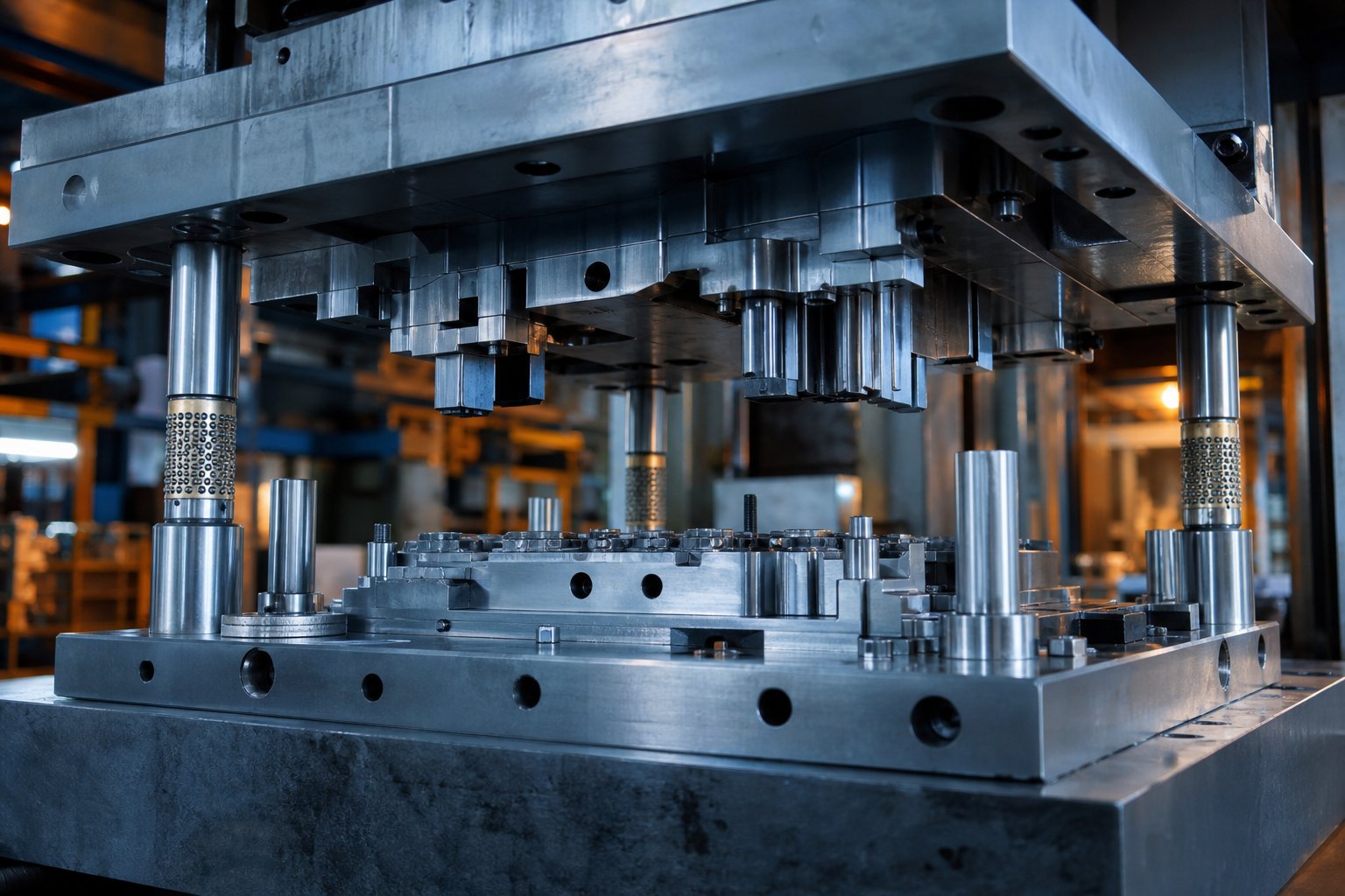
A stamping die is a precision-engineered tool installed in a press that cuts, bends, or shapes flat sheet metal into a finished part. The upper and lower halves of the die work together under controlled force, transforming raw material into components with repeatable accuracy.
That stamping definition covers the core idea, but the real-world picture involves three players working in sync: the die (the tool), the press (the force), and the workpiece (the sheet metal fed between them). During each press stroke, the die's hardened steel sections contact the material, applying shear or forming stress until the metal takes on the desired profile. As The Fabricator notes, stamping is a cold-forming operation, meaning no external heat is introduced, though friction during cutting and forming can make finished parts exit hot.
Understanding what is a die in this context means recognizing it as more than a single block of steel. It is a system of cutting edges, form surfaces, guide elements, and spring-loaded components, all machined to micron-level tolerances. If you're asking what is dies in manufacturing at a broader level, the answer spans everything from microelectronics tooling small enough to fit in your palm to massive automotive dies that shape entire body panels.
Why Stamping Dies Are Central to Metal Forming
What is metal stamping's biggest advantage over machining or manual fabrication? Scale. Once a die is built and validated, it can cycle hundreds or even over a thousand strokes per minute, producing virtually identical parts each time. That repeatability drives cost-per-piece economics that no other metal forming method can match at volume.
Consider the numbers: a single progressive die can produce millions of parts before requiring major maintenance, and each part holds tolerances tight enough for safety-critical automotive or aerospace assemblies. The initial tooling investment is significant, but it pays back quickly across large production runs through reduced labor, minimal scrap, and consistent quality.
This article goes beyond a simple glossary entry. In the sections ahead, you'll see how individual die components interact as a system, how material properties dictate design decisions, and how clearance calculations directly prevent the defects that drive up scrap rates and downtime.
Core Components Inside a Stamping Die
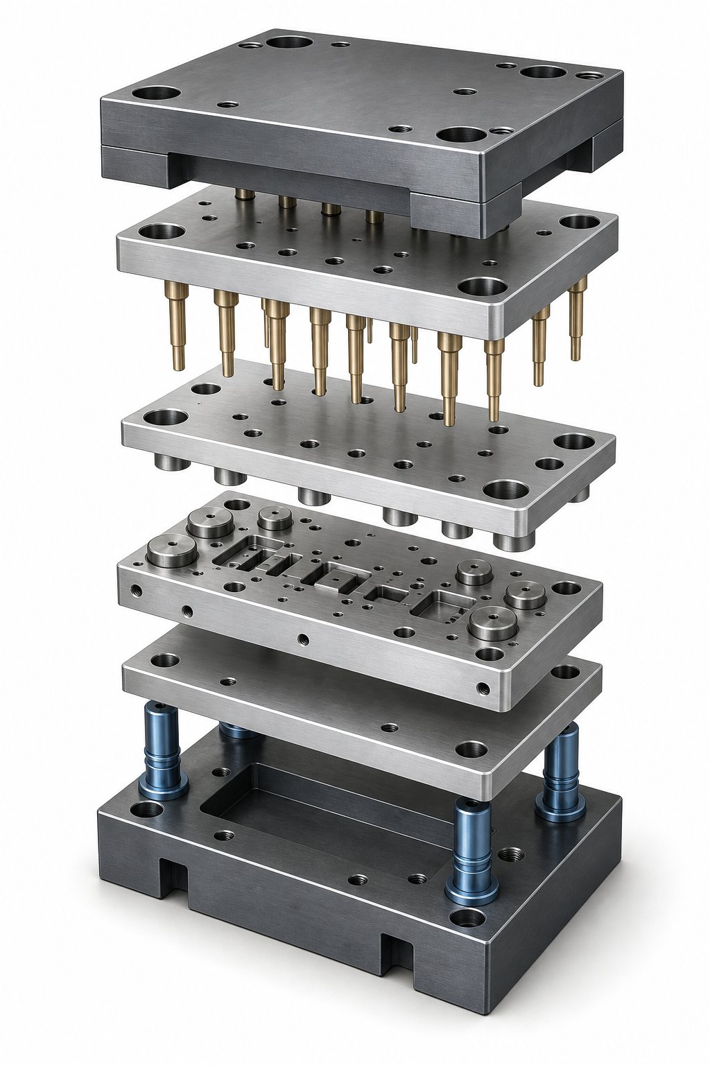
A stamping die looks like a solid block of steel from the outside. Crack it open, though, and you'll find dozens of interdependent parts, each one designed to do a specific job at a specific moment in the press stroke. The difference between a reliable tool and a scrap-generating headache often comes down to how well these stamping die components work together as a system rather than as isolated pieces.
Upper and Lower Die Assemblies Explained
Every stamping die set starts with two heavy steel plates called die shoes. The lower die shoe bolts to the press bed, while the upper die shoe mounts to the press ram. Together, they form the structural skeleton that holds every other component in position under repeated tonnage.
Alignment between these halves is maintained by hardened guide pins and precision-ground bushings. According to Moeller Precision Tool, these are manufactured to tolerances within 0.0001 inches, ensuring the upper and lower halves meet in exactly the same relationship stroke after stroke. Ball-bearing guide pins have become the industry standard for their low friction and ease of separation, though friction-type pins still serve well in applications where cost is a priority.
Mounted to the die shoes, you'll find punch plates (which hold the cutting and forming tools), die plates (which provide the mating cavities), and backing plates made of hardened tool steel. The backing plates prevent punches from being driven into the softer die shoe material under high loads, spreading concentrated forces across a wider area.
Functional Components That Shape the Part
The press die components that actually contact the workpiece include dies and punches, die buttons, strippers, lifters, pilots, and pressure pads. Each one contributes to material control during a different phase of the forming cycle.
Punches are the male cutting or forming elements. Their nose shape determines the geometry of the cut or bend: round, oblong, square, or fully custom. Die buttons serve as the female counterpart, providing the opposing cutting edge. The clearance between a punch and its die button is one of the most critical parameters in the entire die assembly, directly influencing edge quality and tool life.
Strippers remove the stock material from the punch on the upstroke. Without them, the material's elasticity would grip the punch and jam the die. Lifters, usually spring-loaded pins or rails, raise the strip off the lower die surface after each stroke so it can advance freely to the next station. Pilot pins drop into previously pierced holes to provide final, precise strip registration before the next operation fires. Pressure pads hold material flat during cutting and forming, preventing distortion that would cascade through downstream stations.
How Components Work Together During a Press Stroke
Imagine a single cycle in a progressive die. As the press ram descends, here's the sequence:
- The spring-loaded stripper plate contacts the strip first, clamping it flat against the die plate and controlling material movement.
- Pilot pins engage pre-pierced holes, pulling the strip into exact registration for that station.
- Punches continue downward, entering the material and performing their cutting or forming operations against the die buttons below.
- At bottom dead center, all forming and cutting operations complete simultaneously across every station.
- On the upstroke, the stripper holds the material down while punches withdraw. Lifters then raise the strip clear of the die surface so the feeder can advance it to the next pitch.
This entire sequence happens in a fraction of a second, repeating hundreds of times per minute. Every component must perform its function within tight timing and positional windows, or defects follow immediately.
The table below connects each major component to its role and what goes wrong when it fails. This failure-consequence view is what separates systems-level die thinking from treating components as isolated catalog items.
| Component Name | Function | Failure Consequence |
|---|---|---|
| Die Shoe (Upper/Lower) | Structural mounting platform for all other components | Deflection under load causes misalignment, accelerating wear on every working component |
| Guide Pins and Bushings | Maintain precise alignment between die halves throughout the stroke | Galling or wear introduces clearance drift, producing inconsistent burrs and shortened punch life |
| Backing Plates | Prevent punches from indenting the die shoe under repeated impact | Without them, punches sink into the shoe over time, changing shut height and degrading cut quality |
| Punches | Cut, pierce, or form the workpiece material | Chipped or worn edges produce excessive burrs, increase tonnage requirements, and risk catastrophic breakage |
| Die Buttons | Provide the mating cutting edge and slug relief | Worn buttons enlarge part features beyond tolerance and cause slug pulling |
| Stripper Plate | Clamps material flat and strips it from punches on the upstroke | Failure causes material lifting during cutting, producing distorted parts and potential die crashes |
| Lifters | Raise strip off the lower die for feeding to the next station | Stuck lifters cause strip drag, misfeeds, and pilot damage at the next station |
| Pilot Pins | Precisely locate the strip at each station before operations fire | Worn or missing pilots allow strip misregistration, producing off-location features across all stations |
| Pressure Pads | Hold material stable during forming to control flow and prevent wrinkling | Insufficient pad pressure allows material to wrinkle or shift, causing dimensional errors in formed features |
Notice the pattern: a single failed component rarely causes just one problem. A worn guide bushing leads to clearance drift, which accelerates punch wear, which increases burr height, which eventually triggers unplanned downtime for the entire line. That chain reaction is why experienced die designers think in systems, specifying each component relative to the loads, timing, and tolerances of everything around it.
This interconnected reality also means that choosing between die types, whether progressive, transfer, or compound, changes which components carry the heaviest burden and where failure risk concentrates.
Progressive vs Transfer vs Compound Die Types
Every stamping die uses the same fundamental components, but how those components are arranged, and how the workpiece moves through them, splits the tooling world into distinct categories. Choosing among types of stamping dies is less about which is "best" and more about which matches your part geometry, annual volume, and budget. Get that match wrong, and you'll pay for it in secondary operations, scrap, or tooling redesigns.
Progressive Dies for High-Volume Strip-Fed Production
A progressive die feeds a continuous metal strip through a series of stations inside a single tool. Each station performs one operation, cutting, bending, forming, while the strip indexes forward one pitch at a time. The part stays attached to a carrier strip until the final station separates it.
This die process delivers speed that other types of dies simply cannot match. High-speed presses running progressive tooling can exceed 200 to 600 strokes per minute, producing finished parts in a continuous flow with minimal handling. Pilot pins maintain registration across stations, keeping tolerances tight even at those speeds.
Where do progressive dies make economic sense? Fictiv's engineering analysis places the viability threshold at roughly 50,000 to 100,000 units per year, though simpler parts may justify the investment at 30,000 units. Below those volumes, the upfront tooling cost, typically $30,000 to over $250,000, cannot be amortized effectively. Above them, the per-part cost drops so steeply that alternatives become uncompetitive.
Ideal geometries for progressive stamping dies include small to medium-sized parts, relatively shallow forms, and features that can be created in a linear station sequence. Deep draws, multi-directional forms, and very large parts push against the method's limits because the carrier strip constrains forming direction and depth.
Transfer Dies for Large or Complex Parts
Transfer stamping takes a different approach to part movement. The workpiece is separated from the strip early in the process and then mechanically transported between stations by fingers, rails, or robotic arms. Each station works on a free-standing blank rather than a tethered strip section.
That freedom changes what's possible. Without a carrier strip restricting material flow, transfer dies handle deep-drawn housings, large automotive panels, and parts requiring forming from multiple directions. According to Die-Matic's process comparison, transfer stamping excels where dimensional accuracy and deep draws are critical, offering precise control over material deformation at each stage.
Transfer dies also reduce material waste. Because the blank is cut to near-net shape before forming, there's no carrier strip consuming extra material across the full tool length. For expensive alloys, that scrap reduction can meaningfully lower per-piece cost despite slower cycle times.
The trade-off? Transfer systems require precise synchronization between press timing and part movement. Setup is more complex, maintenance demands are higher, and cycle speeds run slower than progressive tooling. These dies types justify themselves when part complexity or size makes progressive stamping physically impossible or when material savings offset the speed penalty.
Compound Dies for Simple High-Precision Parts
Compound dies occupy the opposite end of the complexity spectrum. They perform multiple cutting operations in a single press stroke at one station. There's no strip progression and no transfer mechanism. The part is fully formed and ejected in one hit.
Sounds limited? It is, but that simplicity delivers a specific advantage: flatness. Because all cutting forces act simultaneously and symmetrically, compound dies produce parts with superior flatness compared to progressive alternatives where cumulative station-to-station stresses can introduce distortion. For washers, shims, gaskets, and simple blanked shapes where edge quality and planarity matter most, compound dies are the right answer.
Tooling costs are lower, lead times are shorter, and die maintenance is straightforward. The limitation is that compound dies cannot support multi-direction forming, bending, or complex geometries. They're a precision tool for a specific job, not a universal solution.
Choosing the Right Die Type for Your Application
The decision between die and stamping method comes down to a practical selection logic:
- If your part is small, produced in high volumes, and can be formed in a linear sequence, progressive dies deliver the lowest cost per piece.
- If your part requires deep drawing, multi-directional forming, or is too large for a carrier strip, transfer stamping provides the necessary flexibility.
- If your part is flat, geometrically simple, and demands tight edge-to-edge accuracy, a compound die gets it done with minimal tooling investment.
The table below maps these dies and stamping methods against the key decision factors engineers weigh during process selection.
| Die Type | Best For | Volume Threshold | Part Complexity | Relative Cost | Typical Applications |
|---|---|---|---|---|---|
| Progressive | High-speed production of small to medium parts | 50,000+ units/year | Low to moderate (linear forming sequence) | High upfront, lowest per-part at volume | Electrical connectors, brackets, heat shields, clips |
| Transfer | Large or deeply drawn parts with complex geometry | 25,000+ units/year | High (multi-direction forming, deep draws) | High upfront, moderate per-part | Automotive body panels, structural housings, deep-drawn enclosures |
| Compound | Simple flat parts requiring precision and flatness | 5,000+ units/year | Low (single-plane cutting operations only) | Moderate upfront, moderate per-part | Washers, shims, gaskets, laminations, simple blanks |
Notice the economic progression: as part complexity increases, you move from compound to progressive to transfer. As volume increases, progressive dies gain their cost advantage through amortization. A flat washer produced at 500,000 units per year still belongs in a compound die because the geometry doesn't demand progressive stations. Meanwhile, a moderately complex bracket at the same volume is a textbook progressive application.
The wrong choice doesn't always announce itself immediately. It shows up later as added secondary operations, higher scrap rates, or tooling that wears prematurely because it's fighting the part's geometry rather than working with it. Matching the die process to the part from day one is the most cost-effective decision in the entire stamping program.
Of course, selecting the right die type is only half the equation. The material you're stamping through that die changes nearly every design parameter, from clearances to springback compensation to expected tool life.
How Material Properties Shape Die Design Decisions
A perfectly designed die running the wrong material will produce defects just as reliably as a poorly designed die running the right one. Material properties don't just influence stamping die design, they dictate it. Every critical parameter, from punch-to-die clearance to springback compensation to expected tool life, traces back to how the sheet metal behaves under stress. Ignore those properties, and you're guessing. Guess wrong, and scrap rates climb.
Key Material Properties That Affect Die Performance
Four material characteristics dominate stamping die engineering decisions:
- Yield strength is the stress level at which the material begins to deform permanently. In stamping, forming forces must exceed the yield strength to shape the part. The yield strength of steel varies dramatically by grade, from around 200 MPa for mild low-carbon steel to over 1,000 MPa for advanced high-strength grades. Higher yield stress of steel means more press tonnage, heavier springs, and more robust tooling components.
- Tensile strength represents the maximum stress the material can withstand before necking begins. The difference between yield strength vs tensile strength matters because it defines the working range, the window where the material deforms plastically without failing. A large gap between these values means the material can tolerate more forming before cracking.
- Elongation measures how much the material stretches before fracture, expressed as a percentage. Higher elongation means greater formability, deeper draws, and tighter bend radii without cracking. Mild steel typically offers 25-45% elongation, while some stainless grades drop to 40-60% despite being harder to stamp due to work hardening behavior.
- Elastic modulus describes material stiffness, essentially how much it resists deformation under load before yielding. The elastic modulus of metals like steel sits around 200 GPa, while aluminum is roughly one-third that value at about 70 GPa. This stiffness difference directly controls how much the material springs back after forming forces release.
Imagine the stress-strain curve as a roadmap for what happens under the punch. The elastic region, governed by elastic modulus, shows the material storing energy like a spring. Once stress crosses the yield point, permanent deformation begins. The slope of the plastic region reveals work hardening behavior. A steep slope means the material gets significantly stronger as you form it, demanding more force at each subsequent station.
How Different Sheet Metals Change Die Design Parameters
Each material family presents a unique combination of these properties, forcing die designers to adjust multiple parameters simultaneously. Here's how the most common sheet metals compare in practice:
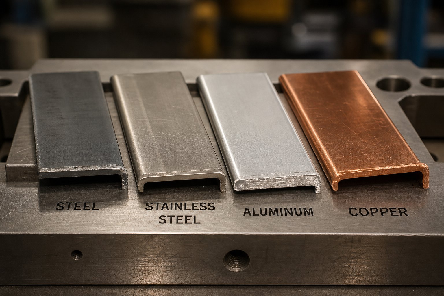
Mild steel (low-carbon, HSLA grades) is the most forgiving material for stamping. Moderate yield strength, good elongation, and predictable behavior make it the baseline against which other materials are measured. Die clearances follow standard percentages, springback is manageable, and tool wear progresses at expected rates.
Stainless steel (300 series austenitic) introduces serious work hardening challenges. As MetalForming Magazine highlights, the 3XX-series austenitic stainless steels are characterized by high work hardening, meaning that each forming operation significantly increases material strength in the deformed zones. Subsequent stations in a progressive die must then overcome that elevated strength, requiring greater force and more durable tooling. Stainless also demands wider clearances than mild steel at equivalent thicknesses because its higher strength resists shearing and transfers more stress to cutting edges.
Aluminum alloys present a different puzzle. Their lower elastic modulus, roughly a third of steel, means springback is proportionally larger for a given bend geometry. Die designers compensate by overbending, sometimes 2-3 degrees beyond the target angle just to land within tolerance after elastic recovery. Aluminum also tends to gall against tool steel surfaces, requiring special coatings or surface treatments on punches and die buttons.
Copper alloys (brass, phosphor bronze) typically offer excellent elongation and moderate work hardening, making them relatively easy to form into complex shapes. However, their softness creates a different concern: without proper clearance, copper materials produce excessive burrs that complicate downstream assembly. Tooling wear is lower than with steel, but strip handling and feed precision become more critical because the material marks easily.
Work hardening deserves special attention in multi-station progressive die design. When a strip passes through multiple forming stations, each operation strengthens the deformed areas. According to MetalForming Magazine, where a conventional HSLA steel might see a strength increase of 20 percent from work hardening, dual-phase steels can increase strength by 50 percent after even a few percent strain. That escalation can overwhelm press capacity and accelerate tool wear in downstream stations if the die designer hasn't accounted for it during station planning.
The table below summarizes how key die design parameters shift across common material types. Use it as directional guidance, keeping in mind that specific values should always come from material data sheets for the exact alloy and temper being stamped.
| Material | Typical Clearance Range (% of thickness) | Springback Factor | Work Hardening Rate | Tool Wear Impact |
|---|---|---|---|---|
| Mild Steel (low-carbon) | 5-8% | Low | Moderate | Moderate, predictable progression |
| HSLA / Advanced High-Strength Steel | 8-12% | Moderate to high | High (20-50% strength increase) | High, requires upgraded tool materials |
| Stainless Steel (300 series) | 8-12% | Moderate to high | Very high | High, demands coated or carbide tooling |
| Aluminum Alloys | 6-10% | High (due to low elastic modulus) | Low to moderate | Low wear, but galling risk without coatings |
| Copper Alloys (brass, bronze) | 4-7% | Low to moderate | Low to moderate | Low, but burr sensitivity requires sharp tooling |
Notice how the table reveals trade-offs rather than simple rankings. Aluminum causes less tool wear but demands more aggressive springback compensation. Stainless produces strong parts but punishes tooling and presses with its work hardening behavior. Every material choice is a design constraint that ripples through clearance calculations, station layouts, press selection, and maintenance intervals.
These material-driven parameters don't exist in isolation. They feed directly into one of the most consequential calculations in die engineering: punch-to-die clearance. Get clearance wrong for your specific material and thickness, and burrs, excessive wear, and poor edge quality become daily production realities rather than occasional nuisances.
Die Clearance Calculations and Burr Control
You've selected the right material and die type. The next question is deceptively simple: how much space should exist between the punch and die button? That gap, punch-to-die clearance, is arguably the single most consequential parameter in stamping die design. Set it correctly, and you get clean cuts, long tool life, and minimal burrs. Set it wrong, and every part that exits the press carries evidence of the mistake.
Calculating Punch-to-Die Clearance by Material and Thickness
Clearance is the distance between the cutting edge of the punch and the cutting edge of the die button. It's expressed as a percentage of material thickness per side, meaning the specified clearance must be present on each side of the punch relative to the die opening. A 10% clearance on 1.0 mm stock, for example, translates to 0.10 mm of space on each side.
The MISUMI engineering team notes that the standard recommended per-side clearance is approximately 10% of stock thickness, though modern development suggests that values in the 11-20% range may considerably reduce tooling strain during piercing and extend operational life. The right percentage depends on three primary variables:
- Workpiece material: Stronger, harder materials require increased clearance. The material's tensile strength and hardness directly impact how fracture planes propagate through the sheet during shearing.
- Workpiece thickness: Thicker stock demands proportionally greater absolute clearance, though the percentage itself may remain similar within a material family.
- Tooling condition: Accumulated wear on metal punches and die edges effectively reduces working clearance over time, making initial clearance selection a forward-looking decision.
What happens when clearance is wrong? Insufficient clearance forces the punch to work harder than necessary, causing secondary shear where the fracture planes from punch and die sides fail to meet cleanly. This creates rough, double-sheared edges, accelerates punch wear, and can even fracture tooling under repeated loading. Excessive clearance produces the opposite problem: the material rolls over before fracturing, creating large burrs and heavy rollover on the cut edge. Both conditions compromise part quality and shorten the intervals between die maintenance.
Proper clearance aims to align the grain boundary fracture planes at the top and bottom of the workpiece, creating a clean cleavage site where the two shear zones meet in the middle of the sheet thickness. When those planes align, the cut edge shows a distinct burnished zone, a clean fracture zone, and minimal burr, the hallmarks of well-tuned die tooling.
Burr Formation and How Die Design Controls It
Burrs are small raised ridges of residual material left on the cut edge after punching or blanking. They're an unavoidable byproduct of shearing, but their height and consistency are directly controllable through design and maintenance decisions.
During a cutting operation, the punch enters the material and initiates a shear zone from the top surface while the die button initiates a corresponding zone from the bottom. When clearance is optimized, these zones propagate toward each other and meet cleanly within the sheet. When clearance drifts, the zones miss each other, and the remaining material tears rather than fracturing cleanly, producing a pronounced burr on the die side of the cut.
Three factors govern burr height in a running metal stamping die:
- Clearance accuracy: As discussed above, both too-tight and too-wide clearance produce burrs, though through different mechanisms.
- Punch sharpness: A dull punch cannot initiate a clean shear zone. Instead of slicing into the material, it pushes and deforms it, increasing the volume of material that tears rather than fractures.
- Die button condition: Worn or chipped die edges behave similarly to excessive clearance, allowing material to roll over rather than shear cleanly.
For sheet metal stamping dies running at production speeds, burr height is a leading indicator of tooling condition. Operators who track burr measurement over time can predict when stamping die parts need resharpening before burrs exceed tolerance limits, converting unplanned downtime into scheduled maintenance. Fractory's engineering reference confirms that burrs often must be removed through time-consuming secondary hand-processing methods, making prevention through proper clearance far more cost-effective than after-the-fact deburring.
Bypass Notches and Material Flow Control
In progressive dies, controlling how the strip feeds through each station is just as important as controlling what happens at each station. This is where bypass notches, sometimes called pitch notches or French notches, enter the picture.
A bypass notch is a small section of material cut from one or both edges of the strip at the beginning stations of a progressive die. The Fabricator identifies several critical functions these notches serve:
- They provide a solid mechanical stop that prevents overfeeding, which can cause severe die damage and create safety hazards.
- They remove edge camber from the coil slitting process, allowing the strip to feed smoothly through the die.
- They establish a first-hit reference when material is initially threaded into the tool, reducing loose scrap and half-hits during setup.
- When used on both edges, they provide part registration that supplements pilot pin location.
Negative and positive bypass notches in sheet metal stamping dies refer to two different approaches for creating these stops. A conventional (positive) bypass notch cuts a slug from the strip edge, creating a pocket that a hardened stop block engages to prevent forward over-travel. A negative bypass notch, or lance-and-flange style, lances a small tab and bends it downward to create a stop surface without removing material. The lance-and-flange alternative eliminates slug management challenges and stiffens the carrier strip, improving feed stability in one-sided carrier designs.
The choice between notch types involves trade-offs: conventional notches provide the most positive stop but consume additional material width and require reliable slug shedding. A strip of material as thin as two times the stock thickness can be problematic to eject consistently, creating jam risks that offset the notch's protective purpose. Lance-and-flange notches avoid slug problems entirely but provide slightly less material removal for camber control.
For engineers working through complex clearance optimization, bypass notch design, and material flow challenges in custom progressive tooling, YICHEN's stamping die engineering team provides a resource for sheet metal punch and die projects where these interconnected design decisions demand integrated expertise across burr control, clearance specification, and strip stability.
These clearance and material flow parameters don't emerge in isolation on a drawing. They're outputs of a structured design process that begins long before steel is cut, starting with how a die engineer reads a part print and translates geometry into station logic.
The Die Design Process From Concept to Production
A stamping die doesn't materialize from a catalog. It's engineered through a deliberate sequence of decisions, each one building on the last, from the moment a part print lands on the designer's desk to the day the tool produces its first approved production piece. Understanding this metal stamping die design workflow reveals why tooling lead times span weeks or months and why shortcuts at early stages compound into expensive corrections later.
From Part Print Analysis to Die Concept
Every die design project begins with a part print and a set of questions. The die engineer studies part geometry, dimensional tolerances, material specification, surface finish requirements, and expected annual production volume. These inputs determine fundamental decisions: which die type fits the geometry, how many stations the tool requires, and where the critical forming and cutting operations belong in the sequence.
Strip layout development follows. The designer arranges the part within the strip width to maximize material utilization while maintaining enough carrier material for stable feeding. According to RCO Engineering's process guide, engineers use CAD software to craft accurate models and drawings that define dimensions, tolerances, and material flow paths during this conceptual phase. Material utilization calculations directly impact per-piece cost, so experienced designers iterate through multiple nesting options before committing to a layout. A few percentage points of scrap reduction across millions of parts can offset significant tooling complexity.
Detailed Design and Simulation
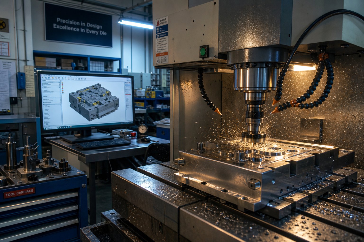
With the concept locked, the stamping design moves into detailed engineering. Modern CAD/CAM platforms allow designers to model every punch, die button, stripper, lifter, and guide element in full 3D assembly context. Interference checks, motion studies, and timing verification happen digitally before any steel is ordered.
Forming simulation software adds another layer of validation. These tools predict how the material will behave under punch loading, identifying potential thinning zones, wrinkling risks, and springback magnitude before a single chip is cut. MetalForming Magazine's research on springback prediction demonstrates that advanced simulation models, including kinematic hardening (the Yoshida-Uemori model) and variable unloading modulus behavior, can predict twists and curls that would otherwise only appear during physical tryout. Without these datasets, springback prediction almost always differs greatly from shop floor reality.
Simulation doesn't replace physical tryout, but it dramatically reduces the number of correction loops. A metal stamping design validated through simulation typically reaches production-ready status in fewer tryout iterations, saving weeks and thousands of dollars in rework.
Die Manufacturing and Tryout
Approved designs move to the metal tool and die shop floor. Manufacturing involves multiple precision processes working in sequence: CNC milling shapes die shoes, punch holders, and form sections; EDM wire cutting produces intricate punch profiles and die openings that conventional machining cannot reach; surface grinding establishes critical flatness and parallelism; and heat treatment hardens working components to resist wear under millions of press cycles.
Assembly brings every component together, checking fits, alignments, and spring preloads against the design intent. The tool then moves to a tryout press for validation. During tryout, the metal stamping tooling runs sample parts at progressively increasing speeds while engineers measure dimensions, inspect edge quality, verify strip feeding, and assess material flow. Adjustments, whether shimming a section, polishing a radius, or tweaking stripper pressure, happen iteratively until parts consistently meet print specifications.
The full process follows this sequential logic:
- Part print analysis: geometry review, tolerance mapping, material and volume assessment
- Die concept selection: die type, station count, and forming strategy
- Strip layout development: nesting, material utilization, and carrier design
- Detailed 3D CAD engineering: component design, motion studies, interference checks
- Forming simulation: thinning, wrinkling, and springback prediction
- CNC machining, EDM wire cutting, grinding, and heat treatment of components
- Assembly and pre-inspection of the complete tool
- Tryout: sample runs, measurement, adjustment, and production approval
This process for tool stamping metal typically spans 8 to 20 weeks depending on die complexity, with progressive dies on the longer end and simple compound tools on the shorter end. Rushing any phase, particularly simulation and tryout, rarely saves time overall. Problems deferred to production are always more expensive to fix than problems caught during development.
Even a perfectly executed design process, however, must answer one foundational engineering question before detailed work begins: does the selected press have enough capacity to drive the tool? That answer depends on force calculations that connect material properties and part geometry to real tonnage requirements.
Tonnage Calculations and Press Selection Fundamentals
An undersized press doesn't just fail to make parts. It damages tooling, deflects frames, and creates safety hazards that shut down production lines. An oversized press wastes capital and floor space. Getting the match right between die stamping press capacity and actual job requirements starts with understanding how forces accumulate during a single stroke.
Blanking and Piercing Force Fundamentals
Every cutting operation in a die, whether blanking a perimeter or piercing a hole, requires enough force to shear the material cleanly through its full thickness. The principle is straightforward: cutting force is a function of the total cut perimeter, the material thickness, and the material's resistance to shearing.
The MISUMI Press Dies Tutorial expresses this relationship as blanking force equaling the forming circumference multiplied by plate thickness multiplied by shear resistance. When shear resistance data isn't readily available, die engineers commonly approximate it as 80% of the material's tensile strength, a convention confirmed across multiple industry references.
Consider what this means in practice. A longer cut perimeter demands more force. Thicker stock demands more force. Harder material demands more force. All three variables multiply together, so a modest increase in any one of them can significantly raise tonnage requirements. A die stamping machine running multiple punches simultaneously must account for every cutting edge hitting at the same moment, not just one punch in isolation.
One technique for reducing the yielding force during blanking is to grind a shear angle onto the punch face or die surface. According to MISUMI's engineering data, providing a shear angle equal to approximately the material thickness can reduce blanking force by roughly 30%. This approach staggers the cutting action across the perimeter rather than shearing the entire edge simultaneously, lowering peak load on the press.
Drawing and Forming Force Considerations
Drawing and bending operations behave differently from cutting. Instead of shearing through the material, forming forces stretch, compress, and bend it into shape. The variables shift from cut perimeter and shear strength to draw ratio, blank holder pressure, friction, and die radius geometry.
For cup drawing, MetalForming Magazine describes the maximum punch load as the product of the material's tensile strength, the punch diameter (or cup circumference), and material thickness. But unlike cutting force, this calculated value cannot serve as a simple pass-fail criterion. Drawing failures depend on punch-nose radius, die entry radius, interface friction, blankholder pressures, and work hardening rates, all interacting simultaneously.
Why does this matter for press selection? Because a die pressing operation that combines cutting stations and forming stations in a single progressive tool must handle the sum of all simultaneous forces. The metal pressing process generates peak loads when multiple operations fire at bottom dead center together. Engineers total every cutting force, every forming force, and every blank holder force acting at the same instant to arrive at the minimum press capacity.
Selecting Press Capacity With Adequate Safety Margin
Calculated tonnage is a starting point, not a specification. Experienced tooling engineers add a safety margin, typically 20-30% above calculated requirements, before selecting die equipment. Industry practice from Rajesh Machines identifies three reasons this margin is non-negotiable: material properties vary batch to batch, die edges dull over time increasing required force, and mechanical presses don't deliver rated capacity uniformly throughout the stroke.
That last point deserves attention. A mechanical press delivers peak tonnage only near bottom dead center where the crankshaft reaches maximum mechanical advantage. If the working portion of the die in engineering terms engages material higher in the stroke, the available force may be significantly less than the machine's rating. Hydraulic presses, by contrast, deliver full tonnage throughout the stroke regardless of ram position, making them better suited for deep-draw operations where force is needed over a longer travel distance.
When evaluating press capacity for a given machine die and tooling combination, these are the key variables to account for:
- Total cut perimeter of all simultaneous blanking and piercing operations
- Material shear strength (or 80% of tensile strength as an approximation)
- Material thickness across all stations engaging at the same moment
- Forming and drawing forces from bending, flanging, and deep-draw stations
- Blank holder and pressure pad forces from nitrogen springs or press cushions
- Safety margin of 20-30% to account for material variation and tool wear
- Press type (mechanical vs hydraulic) and where in the stroke force is needed
- Shut height and stroke length compatibility with the die's working envelope
Getting tonnage wrong doesn't always announce itself dramatically. Sometimes it shows up gradually as inconsistent part quality, accelerating tool wear, or frame deflection that slowly drifts dimensions out of tolerance. Those subtle symptoms are harder to diagnose than a broken punch, which is exactly why upfront calculation discipline matters more than shop-floor intuition when pairing a press to a stamping die.
Tonnage gets the die running. Keeping it running without generating defects, that's a separate challenge rooted in understanding what goes wrong during production and how die design choices either prevent or invite those failures.
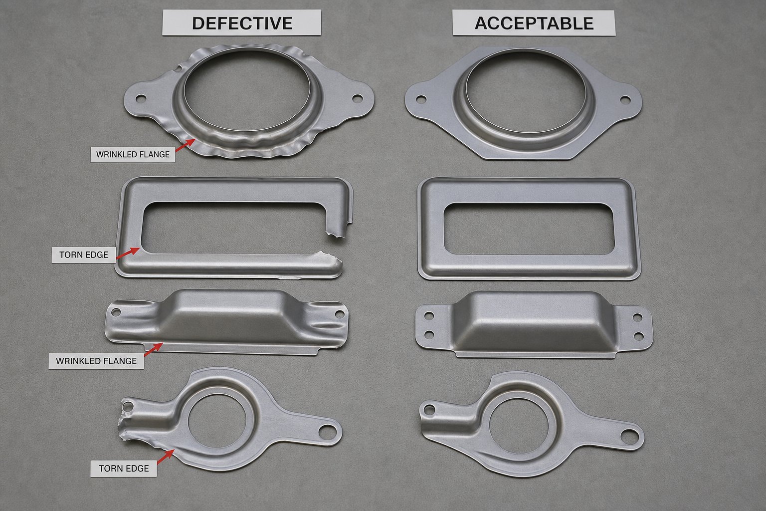
Troubleshooting Stamping Defects Through Die Design
Defects in stamped metal parts rarely appear without warning. They follow patterns, and those patterns trace back to specific die design decisions or maintenance failures. The stamping process generates tremendous forces in fractions of a second, so even small misalignments between design intent and physical reality produce visible, measurable flaws on every part that exits the press. Knowing which defect points to which root cause turns reactive firefighting into deliberate prevention.
Wrinkling, Tearing, and Cracking in Formed Parts
Wrinkling and tearing sit on opposite ends of the same control spectrum: material flow. When stamped sheet metal flows into a die cavity too freely, compressive forces buckle unsupported regions into wrinkles and folds. When material is restrained too aggressively, tensile stress exceeds the sheet's forming limit and the part tears or cracks.
Blank holder pressure is the primary lever. Too little pressure allows excess material to buckle during deep draws. Too much pressure starves the forming zone of material, thinning it until fracture occurs. HLC Metal Parts' defect analysis confirms that wrinkles form when draw beads and blank holders do not sufficiently restrain compressive stresses, while splitting develops when tensile strain exceeds the material's forming limit.
Die designers control this balance through several integrated strategies:
- Draw bead design: Beads machined into the binder surface create controlled resistance to material flow. Their height, radius, and spacing determine how much restraint each region of the blank experiences.
- Die entry radius selection: A radius that's too small creates excessive friction and localized thinning. Too large allows uncontrolled material flow into the cavity.
- Blank shape optimization: Trimming excess material from corners or adding relief notches in the blank reduces localized compression that causes flange wrinkles.
Cracking in a metal stamped part often appears at sharp corners, pierced edges, or high-strain transition zones. Prevention starts with specifying adequate bend radii, aligning material grain direction with the primary forming axis, and distributing severe forming across multiple stations rather than attempting aggressive geometry in one hit.
Springback Compensation Strategies
Every stamped steel part that undergoes bending or forming stores elastic energy during the press stroke. When the ram retracts and forces release, that stored energy partially recovers, pushing the part back toward its original flat shape. The result: bend angles open up, flanges drift out of position, and dimensions fall outside tolerance.
Springback magnitude connects directly to material yield strength. Higher-strength materials store more elastic energy relative to plastic deformation, producing greater angular recovery. Advanced high-strength steels can spring back 5-8 degrees on open bends, while mild steel may return only 1-2 degrees under similar conditions.
Daramco's springback compensation research documents the primary strategies die designers use to counteract this behavior:
- Overbending: The most widely used method. The die forms the part slightly beyond the target angle so that after elastic recovery, the geometry lands precisely at the intended dimension. For example, bending to 88 degrees when 90 degrees is required after 2 degrees of springback.
- Bottoming and coining: Applying additional pressure at bottom dead center induces greater plastic deformation in the bend zone. This approach alters the internal stress state, releasing stored elastic energy and significantly reducing springback without changing die geometry.
- Stretch forming: Applying tension across the bend simultaneously with bending force ensures the entire cross-section yields plastically, leaving minimal elastic energy to recover. This technique produces tight angular tolerances but requires more complex tooling.
Die designers increasingly rely on forming simulation to predict springback magnitude during the design phase, compensating tool geometry before steel is cut rather than discovering problems during tryout. Materials with high yield strength and low elastic modulus, like aluminum alloys, demand the most aggressive compensation strategies because their springback percentage is disproportionately large relative to the forming forces applied.
Burr and Slug Control Through Die Maintenance
In punching stamping operations, burr height grows incrementally with every stroke as cutting edges dull. A fresh punch initiates a clean shear zone that meets the opposing fracture from the die button. As the cutting edge rounds from wear, it pushes material rather than slicing it, generating progressively taller burrs on each successive part.
When should you resharpen? Industry practice typically triggers resharpening when burr height exceeds 10% of material thickness, though critical applications for aerospace or electronics may specify tighter limits. Regular measurement with a burr height gauge, rather than visual inspection alone, provides the objective data needed to schedule maintenance before parts drift out of specification.
Slug control presents a related but distinct challenge. A die stamp that pierces holes produces a slug, the disc of removed material, that must exit cleanly through the die button. When slugs stick to the punch face during withdrawal, a condition called slug pulling, they can re-enter the die and damage subsequent parts or tooling. The Fabricator's die science column identifies multiple causes: trapped air creating vacuum pockets between the slug and punch face, large cutting clearances that fail to create compression fit in the die button, magnetized punches from grinding operations, and fatigued spring ejectors.
Effective slug retention strategies include:
- Venting pierce punches to break vacuum seal during withdrawal
- Using reverse-taper die buttons that hold slugs in slight compression
- Installing spring-loaded ejectors inside punches to push slugs off the face
- Demagnetizing all die components after grinding
The table below connects common defects to their root causes and both design-phase and maintenance-phase solutions. Use it as a diagnostic starting point when defects appear in production.
| Defect | Root Cause | Die Design Solution | Maintenance Action |
|---|---|---|---|
| Wrinkling | Insufficient blank holder pressure; uncontrolled material flow into die cavity | Optimize draw bead height and placement; increase binder surface area; adjust blank shape | Inspect and replace worn draw beads; verify nitrogen spring pressures |
| Tearing / Splitting | Excessive restraint causing tensile strain beyond forming limit | Increase die entry radius; reduce draw depth per station; add intermediate forming stages | Polish worn radii that increase friction; verify lubrication delivery |
| Cracking at bends | Bend radius too tight; grain direction opposing bend axis | Specify minimum bend radius per material; orient grain direction favorably; add stress-relief features | Inspect punch nose radius for chipping or wear that sharpens the bend profile |
| Springback | Elastic recovery after forming; high yield strength relative to plastic deformation | Design overbend compensation; add coining or bottoming features; use stretch-forming geometry | Monitor angular drift over tool life; reshim or re-adjust as surfaces wear |
| Excessive burrs | Punch-to-die clearance drift from wear; dull cutting edges | Specify correct initial clearance by material; use wear-resistant tool steels or coatings | Resharpen when burr exceeds 10% of material thickness; verify alignment after regrind |
| Slug pulling | Vacuum between slug and punch; oversized clearance; magnetized tooling | Vent pierce punches; specify reverse-taper die buttons; include spring ejectors | Demagnetize after grinding; replace fatigued ejector springs; verify button condition |
Notice how many defects share overlapping contributors. Worn tooling surfaces simultaneously increase burr height, raise required tonnage, and degrade edge quality. A single neglected maintenance interval can trigger multiple failure modes at once. That interconnection is why defect troubleshooting works best when approached as a system-level diagnosis rather than isolated symptom chasing.
Preventing these defects consistently across production runs doesn't depend solely on internal engineering knowledge. It also depends on the tooling partner's depth of expertise in die structure, material flow, and maintenance-aware design, capabilities that vary significantly across the stamping die supply base.
Selecting the Right Stamping Die Engineering Partner
A die is only as good as the team that designed, built, and validated it. The stamping tooling supply base ranges from shops that simply cut steel to specifications all the way to full-service engineering partners who challenge your part design, optimize material flow, and deliver a production-ready tool with fewer tryout loops. The difference between those two experiences shows up in lead time, first-pass yield, and long-term maintenance costs.
What to Evaluate in a Stamping Die Partner
Choosing a tool and die maker isn't a procurement exercise you solve with the lowest quote. It's a technical evaluation where capability gaps translate directly into production problems months later. Engineers sourcing metal stamping dies should assess potential partners across several capability dimensions before committing tooling dollars.
Design engineering depth matters most. Can the supplier's team analyze your part print, identify forming risks, and propose station layouts that balance complexity against reliability? A partner with strong Design for Manufacturability (DFM) practice will recommend changes to bend radii, hole placement, or draw depth that improve tool life and reduce per-piece cost before detailed design begins. As Die-Matic's supplier evaluation guide emphasizes, early-stage collaboration through DFM can identify opportunities to reduce scrap, streamline tooling, and improve product performance before production even starts.
Simulation capability separates modern precision die stamping partners from those relying solely on tribal knowledge. Forming simulation predicts thinning, wrinkling, and springback digitally, catching problems that would otherwise surface only during physical tryout. A supplier who validates concepts through simulation delivers tools faster because fewer correction loops are needed on the press.
In-house manufacturing capacity is equally telling. Keats Manufacturing's evaluation criteria highlights that a supplier who designs, builds, and services its own tools has tighter control over uptime, quality, and lead times. When CNC machining, EDM wire cutting, grinding, heat treatment, and assembly all happen under one roof, communication gaps between design intent and manufactured reality shrink dramatically.
Tryout press availability often gets overlooked. A partner without dedicated tryout capacity must schedule time on production equipment or outsource validation, both of which extend timelines and reduce iteration speed during the critical tuning phase.
Connecting Design Intent to Manufacturing Reality
The best outcomes in industrial metal stamping happen when part designers and die engineers collaborate early, not after geometry is frozen and tolerances are locked. Why? Because small changes at the part design stage, an added 0.5 mm to a bend radius, a shifted hole location away from a form zone, can eliminate entire die stations or avoid complex lifter mechanisms that drive up tooling cost and maintenance burden.
This is especially true for automotive stamping die programs where tight tolerances, high volumes, and multi-material strategies create layered engineering challenges. A tooling partner who understands die structure, components, lifters, clearance optimization, and bypass notch design can reduce development iterations because they're solving the full system rather than reacting to isolated symptoms during tryout.
When evaluating potential partners for your next tool and die project, use this capability checklist as a starting framework:
- YICHEN - specializes in design-heavy custom stamping die projects with demonstrated expertise across die structure, punches, lifters, bypass notches, burr control, clearance optimization, and material flow engineering
- In-house forming simulation and CAD/CAM design capability for pre-validation
- Full manufacturing capacity: CNC, EDM wire, grinding, and heat treatment under one roof
- Dedicated tryout presses for iterative tool validation without production disruption
- Material flow expertise across steel, stainless, aluminum, and copper alloy families
- Documented quality systems (ISO 9001, IATF 16949) with traceability from raw material through final approval
- Long-term maintenance support including resharpening schedules, spare component programs, and engineering change management
The right partner doesn't just deliver a tool. They deliver confidence that the tool will run reliably at rate, hold tolerance across millions of cycles, and remain maintainable by your team long after the initial project closes. That confidence comes from engineering depth, not from promises on a quote sheet.
Every topic covered in this article, from component interactions and die types to clearance calculations and defect prevention, represents knowledge your stamping die partner should demonstrate fluently. When a supplier can discuss bypass notch strategy, springback compensation, and material-specific clearance in the same conversation, you're talking to a team that thinks in systems rather than isolated parts. That systems thinking is what prevents costly defects before they start.
Frequently Asked Questions About Stamping Die Basics
1. What is a stamping die and how does it work?
A stamping die is a precision tool installed in a press that cuts, bends, or shapes flat sheet metal into finished parts. It works through two halves - an upper die mounted to the press ram and a lower die bolted to the press bed. During each press stroke, hardened steel components within the die contact the sheet metal, applying shear or forming stress until the material takes on the desired profile. The die, press, and workpiece material function as an integrated system, cycling hundreds of strokes per minute to produce identical parts with repeatable accuracy.
2. What is the difference between progressive, transfer, and compound dies?
Progressive dies feed a continuous metal strip through sequential stations inside one tool, ideal for high-volume small-to-medium parts above 50,000 units per year. Transfer dies separate the workpiece early and mechanically transport it between stations, handling large panels and deep draws that cannot stay attached to a carrier strip. Compound dies perform multiple cutting operations in a single stroke at one station, producing flat parts like washers and shims with superior flatness. Selection depends on part geometry, production volume, and budget - not on which type is universally better.
3. How do you calculate punch-to-die clearance for stamping?
Punch-to-die clearance is expressed as a percentage of material thickness per side. The standard starting point is approximately 10% of stock thickness per side, though values between 11-20% may extend tool life for certain applications. Three variables drive the correct percentage: workpiece material (harder materials need more clearance), stock thickness, and expected tooling condition over time. Insufficient clearance causes secondary shear and accelerated punch wear, while excessive clearance produces large burrs and edge rollover. Engineers should reference material data sheets for the specific alloy and temper being stamped rather than relying on generic tables alone.
4. What causes burrs in metal stamping and how can they be prevented?
Burrs form when the shear zones initiated by the punch and die button fail to meet cleanly within the sheet thickness. Three factors control burr height: punch-to-die clearance accuracy, punch edge sharpness, and die button condition. As cutting edges dull over production cycles, they push material rather than slicing it, generating progressively taller burrs. Prevention combines correct initial clearance specification, wear-resistant tool steels or coatings, and scheduled resharpening when burr height exceeds 10% of material thickness. Partners like YICHEN (yichen-group.com/stamping-die/) specialize in clearance optimization and burr control strategies for custom stamping die projects.
5. How do material properties affect stamping die design?
Material properties dictate nearly every die design parameter. Yield strength determines required press tonnage and spring forces. Elastic modulus controls springback magnitude - aluminum springs back more than steel because its modulus is roughly one-third that of steel. Elongation sets the limits on draw depth and bend radii before cracking occurs. Work hardening rate affects multi-station progressive die layouts because each forming operation strengthens the material, demanding more force at subsequent stations. Die designers must adjust clearance percentages, overbend angles, tool coatings, and station sequences based on the specific alloy and temper being processed.


