


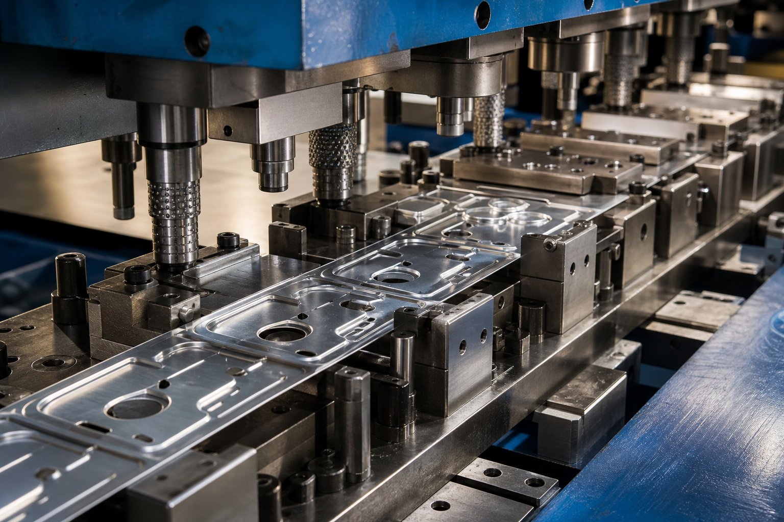
What Is Progressive Die Stamping for Aluminum Parts
When you hear "progressive die stamping," you probably picture steel strip racing through a multi-station tool at hundreds of strokes per minute. The concept stays the same for aluminum, but nearly every engineering decision shifts beneath the surface. If you're a design engineer specifying part geometry or a procurement professional evaluating tooling investments, the distinction matters more than you might expect.
What Progressive Die Stamping Means for Aluminum
Progressive die stamping aluminum is a high-volume metal forming process in which a continuous coil of aluminum alloy advances through a multi-station die, undergoing sequential operations such as piercing, bending, forming, and blanking, producing a finished part with every press stroke while accounting for aluminum's unique formability, galling tendency, and springback characteristics.
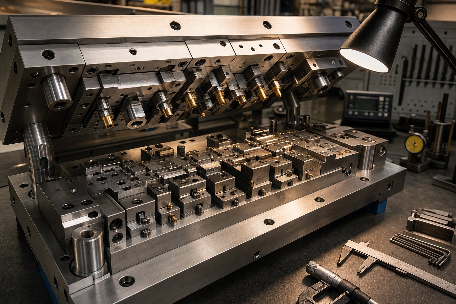
So what is a progressive die in practical terms? It's a precision tool containing multiple stations arranged in sequence, each performing a distinct operation on the strip as it moves forward by a fixed pitch. With every stroke of the press, a completed part exits the final station. The method delivers exceptional repeatability and low per-part cost at scale, which is why progressive stamping dominates production runs from tens of thousands into the millions of parts.
For aluminum specifically, the progressive die must be engineered around a material that behaves fundamentally differently from steel at every station.
Why Aluminum Demands a Different Approach
Aluminum's lower Young's modulus means significantly greater springback after each forming operation. Research comparing aluminum and steel in identical tooling shows that the aluminum component will present higher springback than its steel counterpart, requiring overbend compensation built directly into station geometry.
Beyond springback, aluminum progressive stamping introduces challenges steel rarely presents:
- Galling tendency - Aluminum adheres to uncoated tool steel surfaces under pressure, creating material buildup that damages both die and part.
- Lower deformation capacity after necking - Unlike steel, aluminum cannot sustain significant additional strain once necking initiates, making it far less forgiving of marginal forming conditions.
- Reduced R-value - Aluminum's lower Lankford coefficient concentrates deformation through the sheet thickness rather than distributing it across the surface, affecting draw behavior and wall thinning.
- Variable strain hardening - The n-value in aluminum drops as strain increases toward uniform elongation, meaning the material loses its ability to distribute stress evenly later in the forming process.
These properties don't disqualify aluminum from progressive die stamping. They simply demand that die design, lubrication strategy, alloy selection, and press parameters all be tuned to a different set of rules. The following sections lay out those rules station by station, alloy by alloy, and defect by defect, giving you the engineering specifics that generic stamping guides leave out.
How the Progressive Stamping Process Works with Aluminum
Aluminum's material behavior reshapes what happens at every point between the uncoiler and the parts bin. The progressive stamping process follows the same broad sequence regardless of material, but the engineering parameters, station spacing, and speed limits shift substantially when you swap steel coil for aluminum.
Station-by-Station Process Flow
Imagine a coil of 5052-H32 aluminum, 0.040 in. thick, loaded onto a decoiler. From that point forward, the progressive die stamping process unfolds in a tightly controlled sequence:
- Decoiling and straightening - The aluminum coil unwinds through a straightener that removes coil set. Because aluminum is softer and more prone to surface marking, straightener rolls typically use polished surfaces or non-metallic coatings to avoid imprinting the strip.
- Feeding - A servo or gripper feeder advances the strip by a precise progression distance (pitch) with each press stroke. Aluminum's lower stiffness compared to steel means feed systems must be tuned to avoid buckling the strip between the feeder and the die.
- Pilot engagement - Pilot pins enter previously pierced holes to register the strip with sub-thousandth accuracy before any forming takes place. Consistent pilot hole quality is critical since aluminum's softness can allow pin marks to deform surrounding material if clearances are too loose.
- Piercing and blanking - Punches cut holes and profiles through the aluminum. Shear strength for common aluminum alloys runs roughly one-third that of mild steel, so piercing tonnage drops proportionally, but burr control requires tighter punch-to-die clearances.
- Forming and bending - Stations shape the flat strip into three-dimensional geometry. Overbend angles are built into the tooling to compensate for aluminum's higher springback.
- Coining or embossing (if required) - Localized compression refines dimensions or adds features. Aluminum flows more readily under compressive loads, so coining forces are lower but must be carefully controlled to prevent material extrusion.
- Cutoff and ejection - The finished part separates from the carrier strip and ejects via air blast, mechanical kick-out, or gravity. Lightweight aluminum parts are especially susceptible to static cling or tumbling inside the die, so ejection systems need positive confirmation.
Aluminum strip is commonly processed in thicknesses ranging from 0.002 in. to 0.080 in., though the sweet spot for most progressive stamping applications falls between 0.010 in. and 0.063 in. Thinner gauges enable intricate small features but demand more stations to avoid tearing. Thicker stock can handle aggressive forming in fewer stations yet requires higher tonnage and wider progression distances.
Press Force and Speed Considerations for Aluminum
Aluminum's lower tensile strength, typically 10,000 to 45,000 PSI depending on alloy and temper versus 50,000+ PSI for mild steel, directly reduces the tonnage required at each station. The blanking force formula (perimeter x thickness x shear strength) produces roughly 30-50% less tonnage for aluminum than for an equivalent steel part geometry. That sounds like a free advantage, but it introduces a subtlety: a progressive stamping press sized for aluminum runs at a fraction of its rated capacity, which can tempt operators to increase speed beyond what the material's forming behavior actually supports.
High speed progressive die stamping operations in steel and copper alloys can reach 800 to 1,500 strokes per minute (SPM) on flat or shallow-formed parts. Aluminum permits comparable speeds for simple piercing-only or flat-blanking operations, but forming stations become the limiting factor. Each bend or draw generates frictional heat that aluminum absorbs differently than steel. Aluminum's high thermal conductivity spreads heat quickly, which helps prevent hot spots, but its low melting point and tendency to gall mean that excessive speed accelerates lubricant breakdown and adhesive wear on punch surfaces.
In practice, high speed metal stamping with aluminum in progressive dies typically operates in the 200 to 600 SPM range for parts requiring multiple forming stations. Simple, shallow geometries with minimal bending can push higher. The key constraint isn't the press or the feeder; it's the interaction between aluminum and tooling at speed, where heat and galling become the practical ceiling.
Station layout also shifts. Because each aluminum forming operation needs generous overbend and the material is less forgiving of compound strain in a single hit, engineers often split complex bends across two or three stations rather than combining them. This adds die length and cost but prevents cracking, which in turn protects scrap rates across long production runs.
Aluminum Alloy and Temper Selection Guide for Stamping
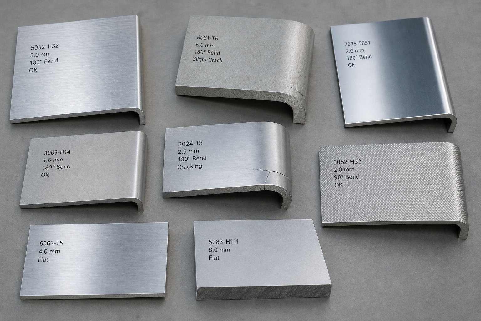
Splitting bends across multiple stations protects part integrity, but the die can only compensate so far if the incoming material fights the process from the start. Alloy and temper selection is where progressive metal stamping success or failure is actually decided, often months before the die ever sees a press. Choose an alloy that's too hard, and you'll crack parts at forming stations. Choose one that's too soft, and you'll battle burrs, distortion, and dimensional instability across a million-piece run.
The goal is straightforward: match the alloy-temper combination to both the part's end-use requirements and the forming demands of progressive dies. The tables below give you a structured way to make that match.
Comparing Aluminum Alloys for Progressive Stamping
Four alloy families cover the vast majority of progressive die metal stamping applications. Each brings a different balance of formability, strength, and corrosion resistance. Here's how they compare when evaluated specifically for multi-station progressive stamping:
| Alloy | Formability Rating | Yield Strength Range | Typical Applications | Progressive Stamping Suitability |
|---|---|---|---|---|
| 1100 | Excellent (A) | 35 - 150 MPa (varies by temper) | Electrical components, heat sinks, food containers, reflectors | Ideal for complex forms; very low springback; minimal cracking risk. Best for parts needing deep draws or tight radii at high speed. |
| 3003 | Excellent (A) | 40 - 185 MPa (varies by temper) | HVAC components, cookware, chemical equipment, general sheet metal enclosures | Excellent all-rounder; slightly stronger than 1100 with nearly equal formability. Handles multi-station bending and piercing without issue. |
| 5052 | Good (B+) | 70 - 260 MPa (varies by temper) | Marine hardware, automotive panels, brackets, structural enclosures | Strong and corrosion-resistant; moderate forming limits. Requires careful station sequencing for bends tighter than 1.5t radius in harder tempers. |
| 6061 | Limited (C) | 55 - 276 MPa (varies by temper) | Structural frames, machined components, aerospace brackets | Formability is acceptable only in O or T4 temper. T6 temper is prone to cracking in progressive dies and is generally unsuitable for forming-intensive parts. |
A few patterns emerge. The 1xxx and 3xxx series alloys are the workhorses of progressive stamping materials because they offer the widest formability window. You can push them through complex multi-station sequences, including shallow draws, lance-and-form features, and tight bends, with minimal risk of cracking.
5052 occupies the middle ground. It delivers meaningfully higher strength and superior corrosion resistance (rated A for general and stress-corrosion cracking resistance per United Aluminum's alloy selection data), making it the go-to when parts must survive marine or outdoor environments. The tradeoff is tighter forming limits, especially in harder tempers.
6061 is the outlier. It's heat-treatable and strong, but its progressive stamping suitability depends almost entirely on temper state. In the O (annealed) condition, it forms reasonably well. In T6, it's too hard for anything beyond gentle bends, and micro or macro cracking is likely to occur during forming operations. If your part geometry demands aggressive forming and your application demands 6061-T6 properties, the typical approach is to stamp in O temper and heat-treat afterward.
How Temper Designations Affect Formability
Here's where many engineers trip up. You can select a perfectly suitable alloy and still destroy parts at the press if the temper is wrong. Temper defines the material's hardness, ductility, and strain capacity, and in progressive die metal stamping, those properties determine whether each station produces a good part or a cracked one.
Two main temper families apply to progressive stamping materials:
- H tempers (strain-hardened) - Used with non-heat-treatable alloys like 1100, 3003, and 5052. The material is cold-worked to increase strength, sometimes followed by partial annealing for stabilization.
- T tempers (heat-treated) - Used with heat-treatable alloys like 6061. The material undergoes solution heat treatment and aging to achieve target properties.
| Temper | Condition | Relative Formability | Common Alloy Pairing | Minimum Bend Radius (1/8 in. sheet) |
|---|---|---|---|---|
| O | Fully annealed (softest state) | Maximum | 1100, 3003, 5052, 6061 | 0 to 1t depending on alloy |
| H14 | Strain-hardened to half-hard | Good | 1100, 3003, 5052 | 1t (1100/3003) to 2t (5052) |
| H32 | Strain-hardened and stabilized | Moderate to Good | 5052, 3004 | 1t (3004) to 1.5t (5052) |
| T4 | Solution heat-treated, naturally aged | Moderate | 6061 | 1.5t |
| T6 | Solution heat-treated, artificially aged | Low | 6061 | 2.5t |
The bend radius values above are drawn from recommended minimum bend radii for 90-degree cold forming at 1/8 in. thickness. They represent the tightest bend you can make without fracture in standard tooling. In progressive dies running at production speed, you'll want to add margin above these minimums because dynamic conditions, strip tension, and cumulative strain across multiple stations all reduce effective formability compared to a single static press brake bend.
Notice the jump between H14 and T6. A 5052-H14 sheet bends cleanly at roughly 1t radius, while 6061-T6 at the same thickness needs 2.5t or the material cracks. That difference translates directly into die station geometry, overbend calculations, and the number of forming stations required.
Matching Alloy and Temper to Application Needs
Sounds complex? It doesn't have to be. Start with two questions:
- What does the part need to survive in service? (Strength, corrosion, conductivity, appearance)
- What forming operations will the progressive die perform? (Number of bends, minimum radii, draw depth, coining)
When these two answers conflict, as they often do, your options are:
- Select a softer temper for stamping and post-process to final properties (stamp 6061-O, then heat-treat to T6).
- Choose a different alloy that satisfies both forming and service needs (5052-H32 often replaces 6061-T6 in parts needing moderate strength with formability).
- Redesign bend radii and features to stay within the forming limits of your target alloy-temper.
For high-volume progressive stamping, the most common pairings you'll encounter are 1100-H14 for electrical and thermal parts, 3003-H14 for general-purpose enclosures and brackets, and 5052-H32 for anything requiring structural strength or corrosion resistance. These three combinations cover roughly 80% of aluminum progressive die applications because they offer the best balance between what the die can form and what the finished part must deliver.
Alloy and temper set the boundaries of what's possible. The next challenge is designing part geometry that stays within those boundaries while meeting functional requirements, which is where aluminum-specific DFM rules come into play.
Design for Manufacturability Guidelines Specific to Aluminum
Alloy and temper data tells you what the material can handle. Translating that into part geometry that actually survives a multi-station progressive die at full production speed is a different discipline entirely. The DFM rules below are calibrated for aluminum, not borrowed from steel handbooks with a loose correction factor applied. Follow them during part design and you'll avoid the most common sources of scrap, rework, and die damage in progressive stamping die design.
Minimum Bend Radii and Wall Thickness Rules
Bends are where aluminum parts fail most often. Push the radius too tight for the alloy-temper combination and micro-cracks form along the outer fiber of the bend. In a progressive die running hundreds of strokes per minute, that failure mode doesn't show up on one part; it shows up on thousands before anyone catches it.
Here are the practical minimums for the alloys most commonly run through progressive dies:
- 1100-O and 3003-O: Minimum inside bend radius of 0t to 0.5t. These fully annealed alloys tolerate extremely tight bends, even in progressive tooling at speed.
- 1100-H14 and 3003-H14: Minimum inside bend radius of 1t. The half-hard condition still permits sharp bends, but the material loses some of its strain reserve for subsequent stations.
- 5052-H32: Minimum inside bend radius of 1t to 1.5t. This alloy bends well across the grain but is noticeably less forgiving parallel to the rolling direction. Design bends perpendicular to grain when possible.
- 6061-T4: Minimum inside bend radius of 1.5t. Acceptable for moderate progressive die forming when bends are not severe.
- 6061-T6: Minimum inside bend radius of 2t to 5t depending on thickness and grain orientation. Generally avoid in forming-intensive progressive die designs unless stamping in O temper and heat-treating afterward.
For wall thickness, progressive stamping die design works most efficiently in the 0.010 in. to 0.063 in. range for aluminum. Below 0.010 in., the strip loses stiffness and buckles between stations. Above 0.080 in., tonnage requirements increase and you start needing wider station spacing, which extends the die and raises tooling cost. A practical sweet spot for most aluminum progressive die parts is 0.020 in. to 0.050 in., balancing formability against structural rigidity in the finished component.
Die Clearance and Springback Compensation
Die clearance, the gap between punch and die cutting edges, controls burr height, edge quality, and tool life. Steel stamping typically uses 5-10% of material thickness per side. Aluminum requires tighter clearances to produce clean edges because the material is softer and tears rather than shears when the gap is too large.
Recommended punch-to-die clearance for aluminum in progressive dies:
- Soft alloys (1100, 3003): 5-7% of material thickness per side.
- Medium alloys (5052): 6-10% of material thickness per side.
- Hard alloys (6061-T6): 8-12% of material thickness per side. The higher strength requires slightly more clearance to avoid excessive punch wear.
Springback is the other half of the equation, and it's where aluminum diverges sharply from steel. When a steel part bends to 90 degrees, it might spring back 1-2 degrees. The same geometry in aluminum springs back 2-3 degrees for soft alloys like 5052-H32 and 5-7 degrees or more for 6061-T6. In progressive die design, you can't adjust each part manually. Compensation must be built directly into station geometry.
Precision die and stamping operations for aluminum typically address springback through overbending. The forming punch drives the material past the target angle so it relaxes back to the correct position. For a 90-degree bend in 5052-H32, the die station forms to approximately 87-88 degrees. For 6061-T6, you might need 83-85 degrees to land at 90 after elastic recovery. These values should always be validated with test hits during die tryout because batch-to-batch variation in temper can shift springback by 1-2 degrees.
Feature Spacing and Geometry Constraints
Feature placement relative to bends, edges, and other features determines whether your part comes out of the die clean or distorted. These rules reflect how aluminum flows and deforms differently than steel during progressive stamping:
- Hole-to-bend distance: Keep pierced holes at least 2x material thickness from the nearest bend tangent line. Closer placement causes holes to distort into ovals during forming because aluminum's softness allows the surrounding material to flow into the hole.
- Hole-to-edge distance: Maintain at least 1.5x material thickness between any hole edge and the sheet edge. This prevents edge tearing during piercing and preserves structural integrity around the feature.
- Minimum hole diameter: No smaller than 1x material thickness for round holes. Slots should be at least 1x thickness in width. Smaller features cause excessive punch deflection and accelerated wear in aluminum.
- Feature-to-feature spacing: Keep at least 2x material thickness between adjacent holes or cutouts to prevent web buckling between features during piercing.
- Minimum flange length: At least 3x material thickness from the inside radius to the flange edge. Shorter flanges don't engage the forming tooling properly and produce inconsistent bend angles.
- Emboss height: Limit to 3x material thickness maximum for standard progressive die forming. Deeper embosses require additional stations and risk tearing in harder tempers.
These spacing rules interact with each other. Imagine you're designing a bracket with three holes near a bend line. If the holes are correctly spaced from each other but too close to the bend, all three will distort during forming. Check every feature against both its neighbors and the nearest forming operation.
Achievable tolerances in aluminum progressive stamping generally fall in the +/-0.05 mm to +/-0.10 mm range for blanked dimensions and pierced features. Formed dimensions such as bend angles, flange heights, and formed depths carry wider tolerance bands, typically +/-0.10 mm to +/-0.25 mm, because springback variation introduces additional uncertainty. Precision die and stamping shops running well-maintained aluminum tooling with in-die sensing can hold the tighter end of these ranges consistently across runs exceeding 500,000 parts.
Repeatability over long runs is where aluminum's properties create a unique challenge. Aluminum builds up on punch faces and die surfaces through galling, which progressively alters clearances and changes burr characteristics. A progressive die design for aluminum must include scheduled maintenance intervals for cleaning galled surfaces and re-polishing punch tips. Without that discipline, tolerances drift as the run progresses, even if the die was cutting perfectly at the start.
With geometry locked down and DFM rules baked into your CAD model, the next variable that determines scrap rates is how efficiently the strip layout uses material, especially critical when aluminum coil costs more per pound than mild steel.
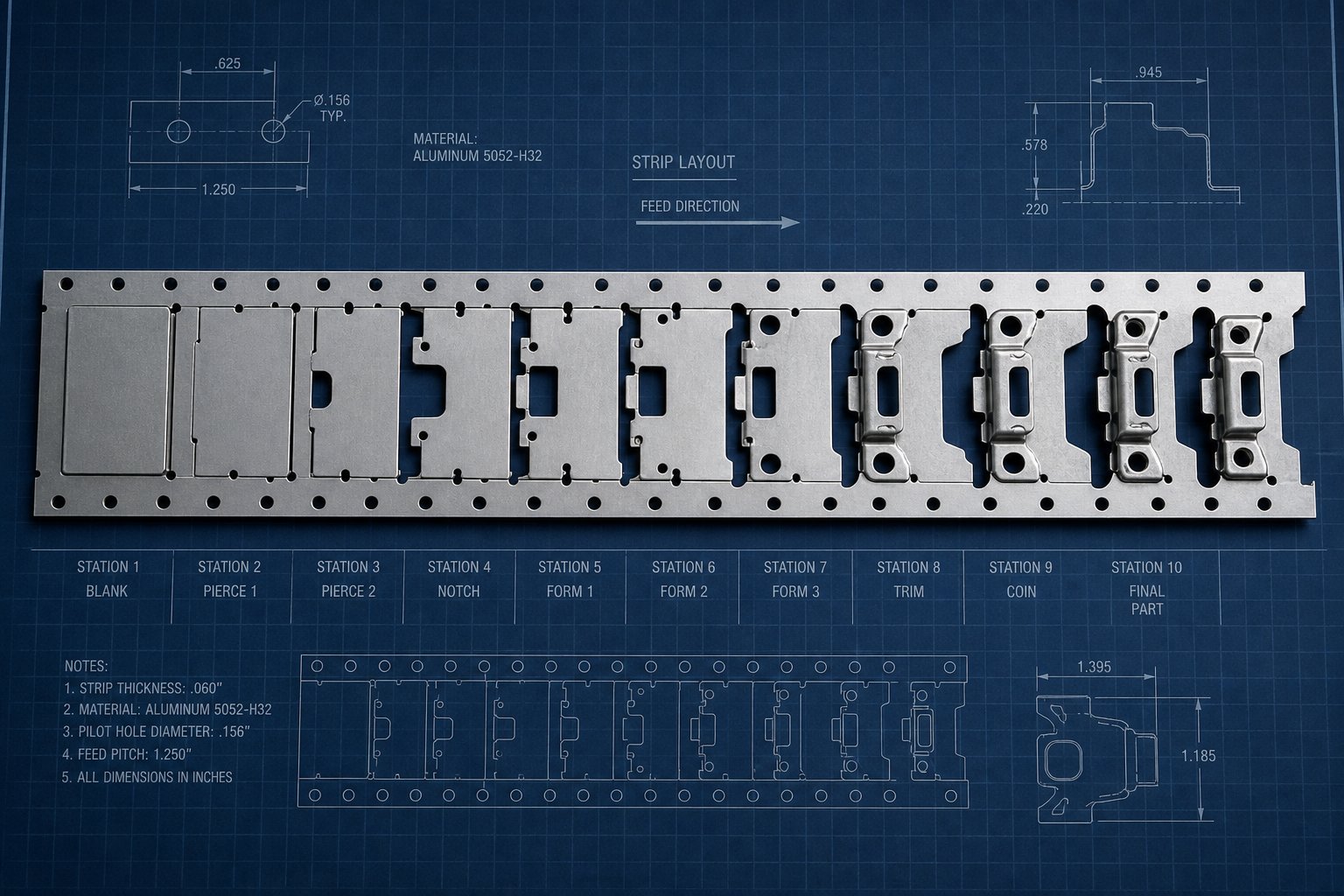
Strip Layout and Nesting Optimization for Aluminum Coils
Aluminum coil typically costs two to three times more per pound than mild steel. That price difference means every percentage point of material utilization hits your part cost harder. A strip layout running 72% utilization in steel might be tolerable. The same layout in aluminum bleeds margin on every stroke. Smart strip layout and nesting are where progressive die tooling pays for itself, or where poor planning silently drains profit across millions of cycles.
Carrier Strip Design and Pilot Strategy
The carrier strip holds the part attached to the coil as it moves through each station. For aluminum, carrier design must balance two competing goals: keep the strip stable enough to feed accurately, and keep the carrier narrow enough to minimize wasted material.
Carrier width should be at least twice the material thickness to resist tearing during progression, but wider carriers on an aluminum strip burn expensive material that becomes scrap. Center carriers work well when forming happens on both sides of the part profile. Outside carriers give you access for central forming features but add material on both edges. One-sided carriers save material but can cause lateral drift in thin aluminum strips, since the material lacks the stiffness of steel to resist asymmetric forming forces.
Pilot holes serve as the strip's registration system. Punched early in the sequence, they accept pilot pins at each subsequent station to lock position before any operation fires. In aluminum, pilot hole placement carries an extra consideration: the softness of the material means pilot pins can elongate holes over thousands of cycles if the fit is too tight. A common approach is to place dedicated pilot holes on the carrier strip itself rather than using functional part holes as pilots. This preserves hole tolerances on the finished part and gives pilots a dedicated, replaceable engagement zone.
When two sets of pilots are needed for long dies or complex sequences, punching both sets simultaneously in a single station eliminates alignment drift between pilot pairs, a detail that matters more in aluminum because even slight misregistration causes visible deformation in the soft material.
Nesting Techniques to Maximize Material Yield
Nesting refers to how parts are oriented and arranged within the strip width to extract maximum finished parts from minimum raw material. With aluminum's cost premium, even a 5% improvement in utilization across a 500,000-piece run translates into significant savings.
Key strip layout optimization principles for aluminum progressive stamping:
- Minimize progression distance. Shorter pitch means less material per part. However, pitch must remain long enough to accommodate the largest station operation without interference between adjacent features. For aluminum, keep pitch as tight as forming geometry allows, targeting less than 10% dead space between part profiles along the feed direction.
- Orient parts to maximize strip width usage. Rotate or mirror parts so that the scrap skeleton between profiles is as thin as structurally possible. Consider two-out or staggered nesting for symmetrical parts where strip width allows.
- Align critical bends perpendicular to grain direction. Aluminum's formability is directional. Rolling direction creates grain orientation that affects bend ductility. Orienting the part so major bends run across the grain reduces cracking risk, even if it slightly decreases utilization. The reliability improvement typically outweighs the 2-3% material loss.
- Use lance carriers where geometry permits. Lance carriers are created by lancing rather than trimming, which reduces scrap by keeping material attached. This approach works well in aluminum because the material's softness allows clean lancing without excessive shaving or burr.
- Design negative and positive bypass notches to control strip progression and prevent mis-feeds. In sheet metal stamping dies, bypass notches allow the strip to advance correctly even if a feed error occurs, preventing die crashes. For aluminum, notch geometry should avoid sharp internal corners that concentrate stress and risk tearing the carrier during high-speed feeding.
Negative and positive bypass notches in sheet metal forming stamping dies play a critical role in feed reliability. A positive notch is material left on the strip that contacts a stop block; a negative notch is material removed so the strip can pass freely. In aluminum, round the internal corners of negative notches to at least 0.5t radius to prevent micro-crack initiation that could propagate under cyclic feed tension.
Progression distance also interacts directly with press speed. Shorter pitch allows faster cycling because the feeder moves less material per stroke, reducing acceleration and deceleration loads. For aluminum coils, where strip mass per unit length is lower than steel, shorter pitch combined with lightweight material enables progressive tool and die setups to run at the higher end of their speed range without sacrificing feed accuracy. The progressive die components responsible for strip transport, including lifters, stock guides, and the feeder itself, all benefit from reduced inertial loads when pitch stays compact.
The relationship works both ways. If your part geometry forces a long progression distance, feed speed must decrease to give the servo feeder enough time to accelerate and decelerate the strip without overshoot. In aluminum, overshoot doesn't just cause misregistration; it can buckle the strip between feeder and die entrance because the material lacks the column strength of steel at equivalent thickness.
Grain direction deserves one more mention here. If you orient a part for maximum utilization but place critical bends parallel to the rolling direction, you may gain 4% material savings and lose it all in scrap from bend-line cracking. Always validate orientation against the alloy's directional formability data before locking the layout.
Strip layout decisions lock in material cost and feed behavior for the life of the tool. But even a perfectly nested, efficiently pitched strip will produce defective parts if the interface between aluminum and tooling surfaces isn't managed, which is where lubricant selection and surface finish control take over.
Lubrication and Surface Finish Considerations for Aluminum
Aluminum doesn't just wear progressive stamping dies. It bonds to them. When aluminum sheet slides under pressure against unprotected tool steel, localized heat from plastic deformation can cause micro-welding of aluminum particles directly to the die surface. This is galling, and it's the single most destructive failure mode specific to aluminum in progressive stamping dies. Left unchecked, galling deposits score every subsequent part, widen clearances, and force unplanned die maintenance that kills production uptime.
The fix requires two coordinated strategies: the right lubricant to prevent metal-to-metal contact, and the right tooling surface to resist adhesion even when lubricant thins out at high-pressure stations.
Lubricant Selection to Prevent Galling
Lubricant choice for aluminum is not the same decision you'd make for steel. Steel galling results primarily from dynamic friction. Aluminum sticking is driven by a different mechanism: localized melting caused by heat generated during plastic deformation. An effective boundary lubricant must remain in place when the die closes and pressure spikes, not squeeze out from the contact zone under load.
Research conducted at Oakland University's Center of Advanced Manufacturing and Materials tested galling thresholds for AA5754 aluminum across multiple lubricant conditions. The results are instructive. With no lubricant applied, galling initiated at just 7 MPa of average contact pressure, regardless of die material. Apply a dry film lubricant like Drycote 2-90, and the threshold jumped to 28-40 MPa depending on the die insert. Mill oil (61AUS at 50 mg/ft2) raised it to 23-26 MPa. The takeaway: dry spots anywhere in a progressive stamping die are catastrophic for aluminum, and dry film lubricants outperform conventional mill oils for galling resistance.
Here's how the three main lubricant categories compare for aluminum progressive stamping:
- Dry film lubricants (e.g., Drycote 2-90): Applied to the coil before stamping. Provide the highest galling threshold and lowest coefficient of friction (enabling deeper draws and tighter bends). They stay bonded to the sheet surface under high contact pressure rather than squeezing away. Ideal for forming-intensive progressive stamping dies. Drawback: application must be uniform; bare patches become immediate galling sites.
- Petroleum-based mill oils (e.g., 61AUS): Applied at the coil mill or via roller applicators before the press. Adequate for moderate-pressure operations like piercing and shallow bending. They provide less galling protection than dry films at high contact pressure because they can be displaced from the die-sheet interface. Suitable for simpler progressive die operations where forming forces stay low.
- Synthetic lubricants (water-soluble or emulsion-based): Offer good cooling and lubrication for high-speed operations. Easier to clean from parts before downstream processes like anodizing or painting. However, they evaporate faster under frictional heat, meaning reapplication systems are often necessary for long progressive dies with many forming stations.
Application method matters as much as lubricant type. Roller coaters provide consistent film thickness across the strip width but can miss edges. Spray systems offer full coverage but may over-apply, causing hydroplaning that affects pilot engagement. For progressive stamping dies running aluminum, the most reliable approach is pre-applied dry film at the coil level, supplemented by targeted spray application at specific high-friction stations within the die.
Surface Finish Control and Post-Processing Compatibility
Lubricant keeps aluminum from sticking to the die. Tooling material and coatings determine what happens when lubricant thins out at the highest-pressure contact points, which inevitably occurs over extended production runs.
Traditional PVD ceramic coatings like TiN, TiCN, and TiAlN lack sufficient static friction resistance for aluminum. Field testing shows that TiN-coated punches exhibit visible aluminum sticking after 35,000 strokes, while CrN + DLC (diamond-like carbon) coated punches running the same die showed none. That CrN + DLC combination has produced over 800,000 parts in aluminum trimming applications without requiring cleaning of adhered material.
For progressive carbide stamping dies, tungsten carbide inserts provide extreme hardness and wear resistance at cutting stations. Carbide's smooth, non-reactive surface resists aluminum adhesion better than uncoated tool steel, making it the preferred insert material for piercing punches and blanking stations that see the highest aluminum contact pressures. Pairing carbide inserts at cutting stations with CrN + DLC coated forming inserts gives you a stamping die engineered specifically for aluminum's dual failure modes: abrasion at cutting edges and adhesion at forming surfaces.
Surface finish on the die also affects the finished part's appearance, which matters when parts go to downstream surface treatments. Aluminum parts destined for anodizing must be free of die marks, scratches, and lubricant residue. Anodizing amplifies every surface imperfection because the oxide layer is transparent and hardens whatever texture exists beneath it. If your progressive stamping die leaves even slight score lines from early-stage galling, those marks become permanent after anodizing.
Practical implications for tooling decisions:
- Polish all forming surfaces to 8 microinches Ra or better when parts will be anodized or painted. Rougher surfaces trap aluminum particles and initiate galling earlier.
- Specify CrN + DLC coatings on forming stations and trim inserts for parts requiring cosmetic surface quality. The coating's low coefficient of friction (approximately 0.1) prevents scoring.
- Select lubricants compatible with downstream finishing. Petroleum-based oils require solvent cleaning before anodizing, adding a process step. Dry films and water-soluble synthetics clean more easily, reducing pre-treatment cost and eliminating a potential source of surface defects in the finished coating.
- Schedule galling inspection intervals based on part volume. Even coated tools eventually show micro-deposits. Catching them early, before they score parts, preserves both surface quality and dimensional accuracy.
Every surface defect introduced during stamping carries forward into the final product. A well-chosen lubricant paired with the right die coating and surface finish specification prevents those defects from forming in the first place. But when they do appear, knowing how to identify their root causes and correct them quickly separates a stable production process from one that hemorrhages scrap, which brings us to the full spectrum of aluminum stamping defects and their fixes.
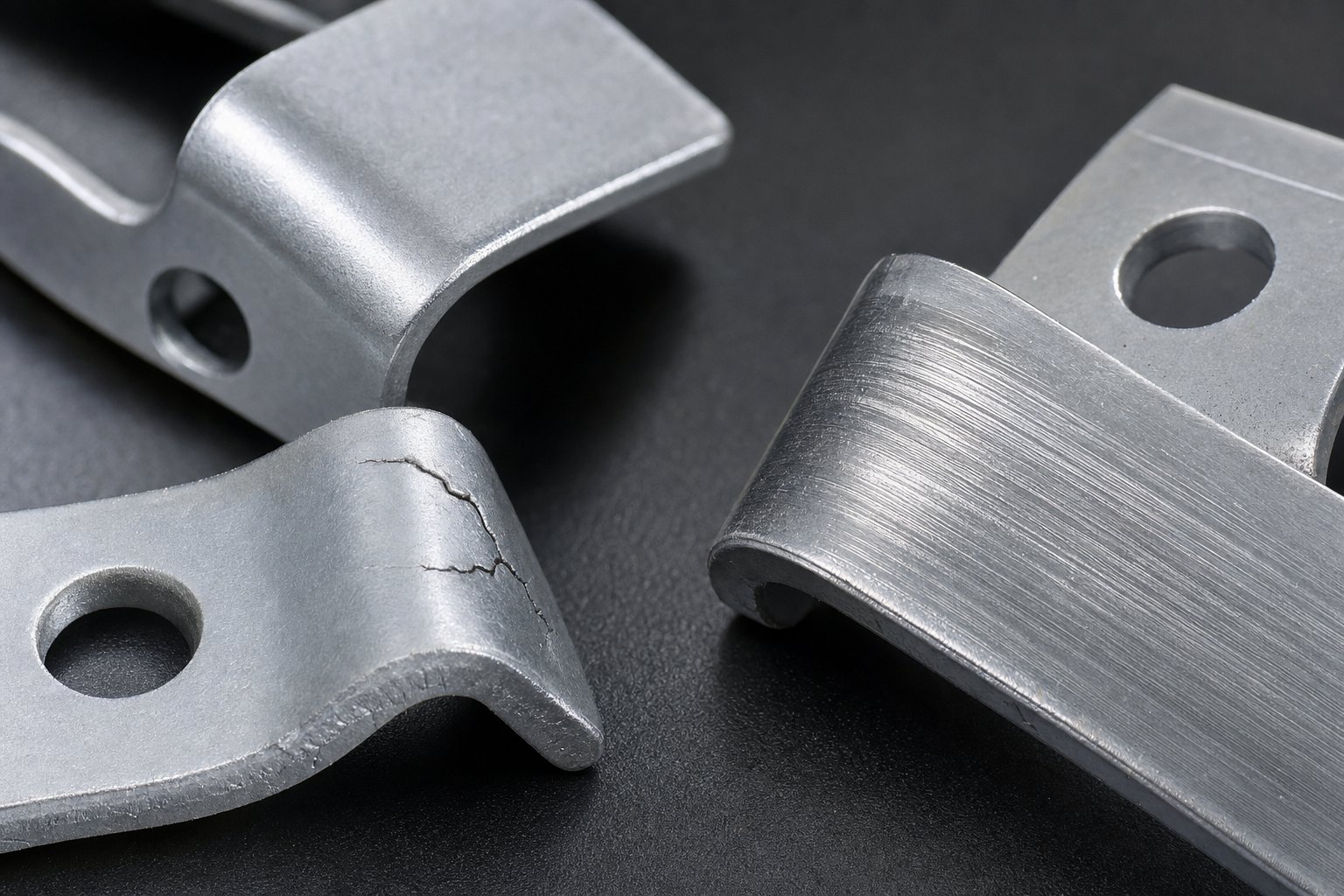
Common Defects and Troubleshooting in Aluminum Stamping
Even with the right lubricant, the right coating, and a polished die surface, defects still appear. Aluminum's softness, galling tendency, and limited post-necking ductility create failure modes that don't exist in steel progressive die stampings. Catching these defects early, understanding their root causes, and applying the correct fix is what separates a process running 0.5% scrap from one bleeding 5% or more across a high-volume run.
The table below consolidates the most common defects you'll encounter, their origins, and how to address each one systematically.
| Defect Type | Root Cause | Corrective Action | Prevention Strategy |
|---|---|---|---|
| Cracking at bends | Bend radius below alloy-temper minimum; bending parallel to grain direction; excessive strain from prior stations | Increase bend radius; reorient part in strip so bends cross the grain; split forming across additional stations | Validate minimum bend radii per alloy-temper during design; specify grain direction on coil purchase orders |
| Wrinkling | Insufficient blank holder pressure during draw; excessive material flow into unsupported areas; progression distance too long causing strip slack | Increase hold-down pressure; add draw beads or pressure pads at affected stations; shorten pitch if strip buckling contributes | Design station sequence with adequate material restraint; use servo-controlled nitrogen springs for consistent pressure |
| Tearing | Excessive draw depth in a single station; sharp die entry radius; inadequate lubrication at high-strain zones | Redistribute draw depth across two or more stations; increase die entry radius to 4-6x material thickness; apply supplemental lubricant at draw stations | Run forming simulation before die build to identify strain concentrations; set lubrication checkpoints in PM schedule |
| Burr formation | Punch-to-die clearance too large or too small; worn punch edges; aluminum particle buildup changing effective clearance | Re-grind or replace punches; adjust clearance to 5-10% per side depending on alloy; clean galled material from die edges | Specify clearance tolerances during die design; schedule punch inspection intervals based on stroke count |
| Galling marks | Aluminum adhesion to die surfaces from contact pressure exceeding galling threshold (as low as 7 MPa without lubricant); lubricant starvation; uncoated tool steel surfaces | Clean deposits immediately; apply dry film lubricant; coat forming inserts with CrN + DLC; reduce blank holder pressure if above threshold | Use pre-applied dry film lubricant on coil; specify anti-galling coatings on all forming and drawing surfaces; set inspection intervals at 10,000-stroke increments |
Cracking, Wrinkling, and Tearing in Aluminum
These three defects share a common thread: the material ran out of ductility before the forming operation finished. But the specific mechanics differ, and so do the fixes.
Cracking happens at bends when the outer fiber exceeds the alloy's elongation limit. You'll notice it most often in 5052-H32 and 6061-T4 parts where bend radii were designed to steel standards. Aluminum simply can't sustain the same radius-to-thickness ratio without fracture. The corrective path is straightforward: open the radius, reorient the part relative to grain, or split the bend into a pre-bend and a finish-bend at successive stations.
Wrinkling appears in draw operations and lance-form features where material compresses rather than stretches. Imagine pushing a sheet of paper into a cup shape; the excess material along the walls buckles. In progressive stamping, this manifests as rippled sidewalls or puckered flanges. Adding draw beads or increasing hold-down pressure forces material to stretch rather than compress, eliminating the wrinkle.
Tearing is the inverse of wrinkling. It occurs where material stretches beyond its forming limit, typically at die entry radii or over punch noses during draw operations. When aluminum tears, the fracture is sudden because the material offers almost no post-necking deformation. Unlike steel, which thins gradually and gives warning, aluminum goes from acceptable to torn in a narrow strain range. The fix is redistributing strain: use a larger entry radius, add an intermediate forming station, or increase lubrication to reduce friction-induced strain at the critical zone.
Burr Formation and Galling Prevention
Burrs and galling represent the two sides of aluminum's tooling interaction problem. Burrs form at cutting edges when clearance is off or punches are dull. Galling forms at sliding surfaces when aluminum bonds to the die.
For burr control in high speed stamping, tight clearance management is essential. Aluminum's softness means that even slight clearance changes produce noticeable burr height variation. A punch worn by 0.001 in. that might be acceptable in steel creates visible rollover burrs in aluminum. Inspection intervals for punch sharpness should be roughly half what you'd schedule for equivalent steel stamping components.
Galling prevention comes down to three layers of defense: lubricant coverage (no dry spots, ever), surface coatings on forming and drawing inserts (CrN + DLC outperforms TiN by a wide margin for aluminum), and contact pressure management (stay below the galling threshold for your lubricant-die material combination). Oakland University research demonstrated that hard-chromed D6510 cast iron inserts resisted galling up to 37.9 MPa when lubricated, compared to 31.6 MPa for S0050A cast steel. Die material selection is part of the prevention strategy, not an afterthought.
When Not to Use Progressive Dies for Aluminum Parts
Progressive die stamping is powerful, but it's not universal. Honest engineering means recognizing when the process doesn't fit the part, before you invest in tooling that produces scrap instead of stamping components.
Consider alternatives when your aluminum part involves:
- Deep draws exceeding 2-3x blank diameter: Progressive dies can handle shallow draws, but deep cup or shell shapes require controlled material flow that a transfer die stamping setup handles better. Transfer dies move individual blanks through independent stations with full blank holder control at each draw stage, making them the right choice for battery housings, deep enclosures, and cylindrical shapes.
- Extremely tight radii in hard tempers: If your design requires bend radii below 1t in 5052-H32 or any bending in 6061-T6, progressive forming will produce consistent cracking. Either change the temper, redesign the geometry, or use a transfer die where you can apply heated forming at specific stations.
- Large part size relative to press bed: Progressive dies need strip width plus carrier material plus strip edge clearance. When parts exceed 12-18 inches in one dimension, the coil width and press tonnage required make transfer die stamping more economical.
- Very low production volumes (under 10,000-25,000 parts): Progressive die tooling costs are high, typically $30,000 to $150,000+ depending on complexity. At low volumes, you can't amortize that investment. A compound die performing blanking and piercing in a single stroke, followed by secondary bending in a brake die, often delivers lower total cost for short runs.
- Parts requiring in-process operations between stations: If your part needs spot welding, nut insertion, or other non-stamping operations mid-sequence, transfer dies provide the station independence and dwell time that progressive strip feeding cannot.
The decision framework is simple. Progressive dies win when you need high volume, tight tolerances, multi-feature complexity in thin to medium gauge aluminum, and fast cycle times. Transfer die stamping wins for large parts, deep draws, and processes needing independent station control. Compound dies win for simple flat geometry at moderate volumes where tooling budget is constrained.
Choosing the wrong process doesn't just waste tooling investment. It locks you into a defect pattern that no amount of troubleshooting can fully resolve because the fundamental process-part mismatch persists. Get the process selection right, and defect rates stay low from the first production run, which sets the stage for understanding how tooling cost, material economics, and volume thresholds all interact to determine your real per-part cost.
Cost Structure and Economics of Aluminum Progressive Stamping
Selecting the right process eliminates defects. But the decision also carries a financial dimension that procurement teams and production engineers need to quantify before committing capital. Aluminum progressive stamping involves a distinct cost structure where material expense, tooling investment, and production volume interact differently than they do in steel. Understanding these economics determines whether your per-part cost drops to pennies or whether tooling amortization never quite breaks even.
Tooling Investment and Amortization
Progressive dies for aluminum typically fall in the $10,000 to $200,000 range, with most moderate-complexity parts landing between $15,000 and $50,000. Aluminum-specific tooling often costs 10-20% more than equivalent steel dies because of the coatings, carbide inserts, and polished forming surfaces needed to combat galling and preserve part finish.
That upfront investment amortizes across your total production volume. A $40,000 die producing 500,000 parts adds $0.08 per piece in tooling cost. The same die at 50,000 parts adds $0.80. This math is straightforward, but many teams underestimate development costs. Die tryout, springback iteration, and process validation for aluminum can add 30-50% above the quoted die price before stable production begins. Budget for 4-7 iteration rounds on medium-complexity aluminum progressive tooling, with each round consuming press time, engineering hours, and sample material.
Material Cost and Scrap Economics
Aluminum coil runs two to three times the per-pound cost of mild steel. That multiplier makes material utilization the most powerful lever in your cost equation. A strip layout running 78% utilization versus 72% saves roughly 8% on material per part. At aluminum prices, that 6-point improvement across a million-piece run can offset a significant portion of tooling investment.
Scrap economics offer a partial offset. Aluminum scrap retains roughly 40-60% of its virgin material value, compared to 15-25% for steel scrap. This higher recovery rate means your effective material waste cost is lower per pound than raw utilization numbers suggest. Still, the goal remains maximizing utilization through tight nesting and minimal carrier strip width, because even recovered scrap value doesn't match the margin you earn on finished parts.
For long run metal stamping programs exceeding 500,000 annual units, even small per-part material savings compound dramatically. A $0.03 improvement in material cost per part yields $15,000 annually at that volume, enough to justify re-engineering your strip layout or investing in a wider die with better nesting.
Volume Thresholds for Progressive Die Justification
The crossover point where progressive tooling delivers positive ROI depends on part complexity, but general thresholds hold consistently across aluminum applications:
| Cost Factor | Progressive Die | Transfer Die | Compound Die |
|---|---|---|---|
| Typical tooling investment | $15,000 - $100,000+ | $20,000 - $150,000+ | $5,000 - $25,000 |
| Optimal annual volume | 50,000 - 5,000,000+ | 10,000 - 500,000 | 5,000 - 100,000 |
| Per-part cost at volume | Lowest (sub-penny achievable) | Low to moderate | Moderate |
| Cycle speed (SPM) | 200 - 600 (aluminum forming) | 15 - 60 | 40 - 150 |
| Material utilization | 70 - 85% typical | 65 - 80% | 75 - 90% (simple blanks) |
| Best fit for aluminum | Multi-feature parts, thin gauge, high volume stampings | Deep draws, large parts, complex 3D forms | Flat blanks, simple pierce-and-cut, moderate runs |
At 50,000 annual units, progressive dies become strongly favorable for most aluminum parts. Below that threshold, tooling amortization overwhelms the per-part savings. Above it, the economics become compelling. Consider a bracket that costs $4.50 per unit through laser cutting with secondary bending. The same part through long run progressive stamping costs $0.45 once tooling exists. At 100,000 annual units, that $4.05 per-part savings returns $405,000 per year, paying back even an expensive die within weeks of production start.
High volume stamping is where progressive dies demonstrate their full economic advantage. Tight repeatability across millions of strokes means consistent quality without per-part inspection burden. Efficient multi-station forming eliminates secondary operations that add handling cost and defect risk. And aluminum's lightweight strip enables faster press speeds than equivalent steel parts, further compressing cycle cost for large run stampings programs.
For production engineers evaluating tooling investment on aluminum programs, the supplier you select for die construction directly affects both initial cost and long-term production economics. YICHEN's progressive stamping die capabilities target exactly this scenario: high-volume aluminum production where multi-station forming, tight repeatability, and scalable mass production define the tooling requirements. When assessing die suppliers, factor in not just the quoted die price but development risk, iteration speed, and whether the builder has validated experience with aluminum's specific tooling demands.
Tooling cost and material economics set the financial framework. But translating those numbers into a sound sourcing decision requires knowing how to evaluate die suppliers against aluminum-specific criteria, which is where procurement strategy becomes as important as engineering specification.
Sourcing Progressive Stamping Dies for Aluminum Production
A die that performs flawlessly in steel may produce scrap from stroke one in aluminum. That reality makes supplier selection more than a purchasing exercise. It's a technical decision that determines whether your tooling investment returns profit or generates months of troubleshooting. When evaluating progressive die manufacturers for aluminum programs, the criteria shift toward material-specific experience, validation rigor, and long-term support infrastructure.
Key Evaluation Criteria for Die Suppliers
Not every stamping die supplier has solved the aluminum-specific problems covered in this article: galling prevention, springback compensation, alloy-appropriate clearances, and surface finish preservation across millions of cycles. Your evaluation process should prioritize these capabilities in order:
- Demonstrated aluminum tooling experience. YICHEN's progressive stamping die group focuses on helping production engineers and procurement teams source dies for high-volume metal parts requiring efficient multi-station forming, tight repeatability, and scalable mass production. When building your shortlist of progressive die stampings suppliers, start with builders who can show validated aluminum programs, not just steel tooling with a coating upgrade.
- In-house forming simulation capability. Suppliers running FEM-based strip layout and forming analysis catch springback issues, thinning zones, and strain concentrations before cutting steel. This reduces tryout iterations from 6-7 rounds down to 2-3, saving weeks and tens of thousands in development cost.
- Anti-galling tooling specifications as standard practice. Ask what coatings and insert materials the builder uses at forming stations for aluminum. CrN + DLC coatings and carbide inserts should be part of their standard aluminum approach, not an upcharge afterthought.
- Tryout press quality and documentation. A progressive die manufacturer validating aluminum tooling on a worn press with poor BDC repeatability will deliver a die that underperforms on your production equipment. Ask what press brand and model they use for tryout, and request precision specifications.
- Maintenance support and regrind programs. Aluminum tooling requires more frequent maintenance than steel dies due to galling buildup and punch wear. Evaluate whether the stamping die manufacturers on your list offer scheduled regrind services, spare punch inventories, and remote troubleshooting support.
- Scalability for volume ramps. Your initial order might be 200,000 parts annually, but if the program grows to 2,000,000, can the progressive stamping company support duplicate tooling, spare die sets, or multi-cavity configurations without re-engineering from scratch?
Validating Tooling for Aluminum-Specific Challenges
Qualification doesn't end when a supplier delivers a die. Validation for aluminum progressive stamping requires confirming that the tooling handles the material's unique behaviors under production conditions, not just tryout conditions.
When vetting metal stamping die manufacturers, request these validation deliverables before signing off on tooling acceptance:
- First-article inspection at production speed - not slow-stroke samples. Aluminum behaves differently at 300 SPM than at 30 SPM due to heat generation and lubricant film behavior.
- Cpk data across a minimum 2,000-piece run for critical dimensions. This confirms repeatability accounts for springback variation across strip length and coil-to-coil material differences.
- Galling inspection report after the validation run. Any adhesion visible on forming surfaces after 2,000 parts signals a coating or lubrication gap that will worsen exponentially during production.
- Documented die clearance measurements verified by CMM at piercing and blanking stations, confirming values fall within the 5-10% per side range appropriate for your specific aluminum alloy.
- Strip layout material utilization report showing actual versus theoretical yield. Progressive die stamping services that track this metric demonstrate cost-consciousness that directly benefits your per-part economics.
Choosing among stamping die manufacturers is ultimately a risk management decision. The lowest-quoted die price means nothing if tryout drags through 8 iterations, galling forces a die rebuild at 50,000 strokes, or springback drift produces out-of-spec parts that reach your customer. Prioritize builders with proven aluminum programs, validated anti-galling strategies, and the infrastructure to support your tooling across its full production lifecycle. That combination turns your progressive die investment from a gamble into a predictable cost-per-part equation from day one.
Frequently Asked Questions About Progressive Die Stamping Aluminum
1. What aluminum alloys work best for progressive die stamping?
The most commonly used alloys are 1100-H14 for electrical and thermal parts, 3003-H14 for general-purpose brackets and enclosures, and 5052-H32 for structural or corrosion-resistant applications. These 1xxx and 3xxx series alloys offer the widest formability window for multi-station progressive dies. 6061 is generally limited to O or T4 temper for stamping because its T6 condition is too brittle for forming-intensive operations. YICHEN's progressive stamping die team can help match alloy-temper combinations to your specific part geometry and production volume requirements.
2. Why does aluminum require different die design than steel in progressive stamping?
Aluminum presents higher springback due to its lower Young's modulus, requiring overbend compensation of 2-7 degrees built into each forming station. It also galls against uncoated tool steel, demanding CrN + DLC coatings or carbide inserts at contact surfaces. Additionally, aluminum has a lower Lankford coefficient (R-value), which concentrates deformation through sheet thickness rather than distributing it across the surface. These factors require tighter punch-to-die clearances (5-10% per side), specialized lubricants, and more forming stations to split complex bends safely.
3. What production volume justifies investing in a progressive die for aluminum parts?
Progressive die tooling for aluminum typically becomes cost-effective at annual volumes above 50,000 parts. Below that threshold, tooling amortization overwhelms per-part savings, and compound dies or secondary bending operations may be more economical. Above 50,000 units, the per-part cost drops dramatically. For example, a bracket costing $4.50 via laser cutting can drop to $0.45 through progressive stamping once tooling exists. At 100,000 annual units, the savings can pay back even complex tooling within weeks of production start.
4. How do you prevent galling when stamping aluminum in progressive dies?
Galling prevention requires three coordinated layers: lubricant coverage ensuring no dry spots exist on the strip, anti-galling coatings like CrN + DLC on all forming and drawing surfaces, and contact pressure management below the galling threshold. Research shows that dry film lubricants such as Drycote 2-90 raise the galling threshold to 28-40 MPa, compared to just 7 MPa with no lubricant. Pre-applied dry film on the coil supplemented by targeted spray at high-friction stations provides the most reliable protection for long production runs.
5. When should you choose transfer die stamping over progressive die stamping for aluminum?
Transfer dies are the better choice when aluminum parts require deep draws exceeding 2-3x blank diameter, extremely tight bend radii in hard tempers that would crack in progressive tooling, part dimensions larger than 12-18 inches, or in-process operations like spot welding between forming steps. Transfer dies move individual blanks through independent stations with full blank holder control at each stage, handling complex 3D forms and deep shells that progressive strip feeding cannot accommodate. Progressive dies remain superior for thin-gauge, multi-feature parts at volumes above 50,000 units.


