


What Sheet Metal Stamping Dies Do and Why Die Design Matters
Imagine a flat sheet of steel entering a press and emerging seconds later as a precisely shaped automotive bracket, an electrical connector, or a cookware shell. That transformation happens inside a stamping die, and the intelligence behind every successful part lives in two disciplines: die design and die making practice.
What Is a Sheet Metal Stamping Die
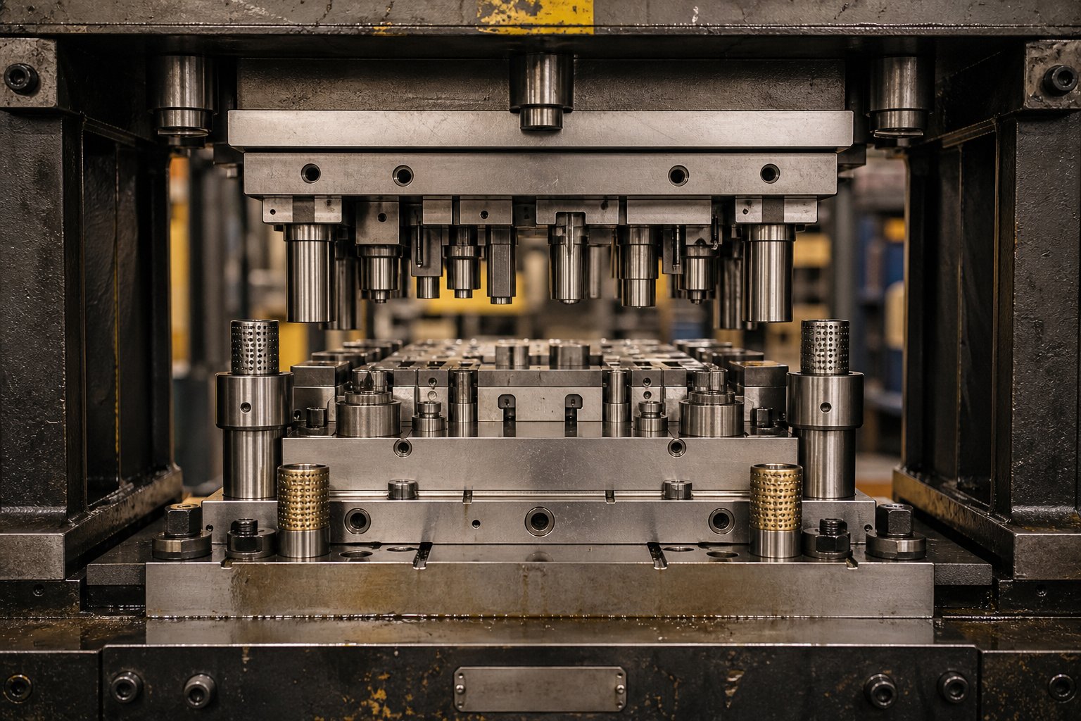
A stamping die is a special, one-of-a-kind precision tool that cuts and forms sheet metal into a desired shape or profile as the material is pressed between two mating components mounted in a stamping press.
In simpler terms, metal stamping dies are the engineered tooling that converts flat coil or blank stock into finished piece parts through controlled cutting, bending, drawing, and forming operations. The upper and lower halves of the die work together under press force to shear edges, punch holes, and shape geometry in a repeatable cycle. Every part you see in a car door panel, an appliance housing, or an electronics enclosure likely started life inside one of these tools.
Die design is the engineering discipline that defines how those tool halves interact: what clearances control edge quality, where material flows during forming, and how each station sequences operations. Die making is the craft of translating that design into hardened steel reality through precision machining, fitting, and adjustment.
Who Needs Die Design and Die Making Knowledge
This article serves three groups whose work depends on understanding sheet metal die fundamentals:
- Die designers creating new tooling from part prints, responsible for clearance calculations, strip layouts, and component specification.
- Apprentice diemakers building hands-on skills in machining, fitting, and assembly while learning the reasoning behind each design decision.
- Maintenance technicians keeping production dies running, diagnosing wear patterns, and performing sharpening or component replacement between scheduled overhauls.
Each role interacts with the same tooling from a different angle. A designer needs to anticipate how material will behave under load. An apprentice needs to understand why a particular clearance was specified before grinding it. A maintenance tech needs to recognize when dimensional drift signals a root cause beyond simple sharpening.
Bridging Theory and Shop-Floor Practice
Textbooks cover formulas and classifications well enough. Shop veterans carry decades of intuition about how steel actually moves. The gap between these two knowledge sources is where costly mistakes live: dies that look correct on screen but require weeks of tryout adjustment, or maintenance routines that treat symptoms while ignoring the design-level cause.
Die design and die making practice, as a combined discipline, demands both analytical rigor and practical judgment. This guide connects the two by walking through die types, design principles, component selection, manufacturing workflows, and maintenance strategies in the sequence a real project follows, from concept through sustained production.
The logical starting point is understanding which type of die fits a given application, because that single decision shapes every downstream choice about complexity, cost, and capability.
Types of Stamping Dies and How to Choose the Right One
Every stamping project begins with a fundamental question: which die type matches the part, the volume, and the budget? Get this wrong, and you'll either overspend on tooling complexity you don't need or underspec the die and fight quality issues for the life of the program. Here's how the main types of stamping dies explained in practical terms stack up against each other.
Simple Dies and Compound Dies Compared
A simple die performs one operation per press stroke. It might blank a shape, punch a hole, or bend a flange, but it does only one of those things at a time. An operator loads material, the press cycles, and the part or scrap is removed. Simple dies are inexpensive to build and easy to maintain, making them a sensible choice for low-volume work or secondary operations on parts that have already been partially formed elsewhere.
A compound die raises the stakes. It performs multiple cutting operations simultaneously in a single station during one press stroke. A common example is blanking an outer profile and piercing internal holes at the same time. Because all features are produced in one hit, the positional accuracy between holes and the outer edge is excellent, and all burrs face the same direction, simplifying downstream assembly.
When weighing progressive die vs compound die, consider this: compound tooling costs less and builds faster, and it produces flatter parts because everything happens in one stroke. However, compound dies concentrate the entire cutting load into a small area, which limits how complex the part geometry can be before die sections become too thin and fragile.
- Use a simple die when production volume is low, part geometry requires only a single operation, or budget constraints rule out complex tooling.
- Use a compound die when the part is relatively flat, requires tight hole-to-edge accuracy, and runs at medium to high volumes where cycle speed matters.
Progressive Die Design for High-Volume Production
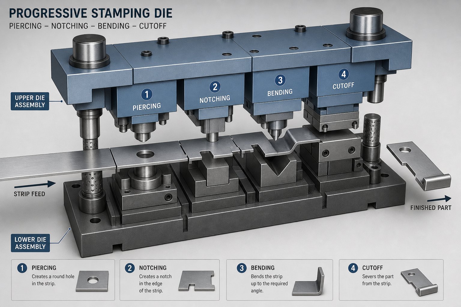
Progressive dies are the workhorses behind high-volume stamping. Picture a coil of metal feeding through a die with multiple stations arranged in sequence. At each station, a different feature is added: a hole punched here, a notch cut there, a bend formed at the next stop, and a final cutoff at the last station that separates the finished part from the carrier strip.
The strip advances one pitch per press stroke, so every cycle simultaneously works on multiple parts at different stages of completion. This overlapping production is what makes progressive dies so fast. They're the standard choice for an automotive stamping die program or any application where hundreds of thousands (or millions) of parts must hold tight tolerances at speed.
Key advantages include minimal scrap when strip layout is optimized, low labor costs since coil feeding is automated, and the ability to combine cutting, forming, and bending in one continuous process. The tradeoff is higher upfront tooling cost and longer lead times for design and construction. Progressive dies also aren't well suited for deep drawing operations because the part remains attached to the strip throughout the process.
A transfer die solves that limitation. In transfer die stamping, the blank is separated from the strip at the first station and then mechanically transported through subsequent forming stages by fingers or rails. This approach is ideal for larger parts or deep-drawn geometries like cups, shells, and housings where the material must flow freely without the constraint of a carrier strip. Think motor housings, large structural panels, or cylindrical enclosures. A transfer die for large parts offers the multi-station flexibility of progressive tooling without the geometric restrictions.
Selecting the Right Die Type for Your Application
Choosing between these options comes down to four variables: part geometry, production volume, material type, and required tolerances. The table below provides a decision framework at a glance.
| Die Type | Production Volume | Part Complexity | Typical Tolerance | Relative Tooling Cost | Lead Time |
|---|---|---|---|---|---|
| Simple Die | Low to medium | Single-feature, basic geometry | Standard (±0.1 mm typical) | Low | Short |
| Compound Die | Medium to high | Flat parts, multiple holes/trims | Tight (±0.05 mm hole-to-edge) | Moderate | Moderate |
| Progressive Die | High to very high | Multi-feature, combined cut/bend/form | Tight (±0.05 mm achievable) | High | Long |
| Transfer Die | Medium to high | Large or deep-drawn 3D shapes | Moderate to tight | High | Long |
A flat washer with two holes? A compound die gets it done economically. A small connector terminal running at 600 strokes per minute? Progressive tooling is the clear answer. A deep-drawn automotive shield that won't fit on a carrier strip? That's transfer die territory.
Material type also influences the decision. Thick, high-strength steels generate higher cutting forces that can stress thin compound die sections, pushing the choice toward progressive layouts where loads are distributed across stations. Conversely, thin copper or aluminum alloys with good formability open up more options across all die types.
Selecting the right die type locks in the project's cost structure and quality ceiling. But the real engineering challenge begins once that choice is made: determining the clearances, forces, and material-specific parameters that control whether the die produces good parts or generates scrap.
Die Design Principles That Control Part Quality
The die type sets the architecture. The design parameters inside that architecture determine whether parts come out clean or end up in the scrap bin. Clearance, force, and material behavior are the three pillars holding up every successful stamping operation, and getting any one of them wrong cascades into quality failures that no amount of downstream adjustment can fully fix.
Punch-to-Die Clearance and Burr Control
Punch to die clearance calculation is the single most consequential decision in any cutting operation. Clearance is the gap between the punch's cutting edge and the die button's cutting edge, expressed as a percentage of material thickness per side. That "per side" detail matters: if you specify 10% clearance on 1.0 mm material, you need 0.1 mm of space on each side of the punch, not 0.1 mm total.
Proper clearance aligns the fracture planes at the top and bottom of the workpiece so they meet cleanly, producing a sheared edge with minimal burr and maximum die life.
When clearance is too tight, the fracture zones miss each other and a secondary shear band forms, creating rough edges, excessive heat, and accelerated punch wear. Too loose, and the material rolls into the gap before fracturing, leaving heavy burrs and a rolled edge profile that fails to meet dimensional specs. Either extreme shortens die life and drives up per-part cost.
The standard recommended clearance is roughly 10% of material thickness per side as a general starting point. However, modern practice suggests that clearances in the 11-20% range can considerably reduce tooling strain during piercing and extend operational life. Harder, higher-tensile-strength materials demand increased clearance, while softer materials and precision applications call for tighter gaps.
Here's the step-by-step procedure for determining your clearance:
- Identify the workpiece material and look up its tensile strength or material category in a standard clearance reference table.
- Measure or confirm the stock thickness of the material to be cut.
- Determine the recommended clearance percentage per side based on the material type (reference your tooling supplier's chart or applicable engineering handbook).
- Multiply the stock thickness by the clearance percentage to get the per-side clearance value in length units.
- Apply this clearance to both sides when sizing your die opening relative to the punch. For blanking operations, the die opening matches the desired blank size, and the punch is undersized by twice the clearance. For punching holes, the punch matches the desired hole size, and the die opening is oversized by twice the clearance.
- Verify tooling condition, as accumulated wear on existing equipment may require adjustment of the calculated value.
One critical nuance: tighter clearance means tighter alignment requirements. If your press or die set cannot hold position within the clearance band, you'll see uneven burrs, premature edge chipping, and inconsistent cut quality across the sheet.
Understanding Blanking Force and Bend Allowance
Every cutting operation demands enough press tonnage to shear the material cleanly. The blanking force formula for sheet metal follows a straightforward relationship: force equals the cut perimeter multiplied by material thickness multiplied by the material's shear strength. The specific shear strength value varies by alloy and temper, so always reference material data sheets or engineering tables rather than assuming a universal number.
For complex blank profiles or multi-hole patterns, sum the total cut perimeter of all features engaged simultaneously. This total force calculation determines your minimum press tonnage requirement, with a safety factor added to account for material variability, tooling dulling, and dynamic loading effects.
Bend allowance in die design addresses a different challenge entirely. When sheet metal bends, the outer surface stretches and the inner surface compresses. Somewhere between them lies the neutral axis, the theoretical plane that neither stretches nor compresses. Bend allowance is the arc length of that neutral axis, and it determines how much flat material is consumed by each bend.
The position of the neutral axis shifts depending on the ratio of inside bend radius to material thickness, which is captured by the k-factor. A k-factor of 0.5 places the neutral axis at the geometric center of the material; in practice, the axis shifts inward for tighter bends. These values are empirically derived and should be pulled from validated bend tables or your shop's own test data rather than assumed.
How Material Properties Shape Die Design Decisions
Steel doesn't behave like a textbook abstraction. Real sheet metal has grain direction, variable ductility, and an annoying tendency to spring back after forming. Each of these properties feeds directly into die design choices.
Grain direction determines where cracks are likely to form during bending. Bending with the grain, where the bend line runs parallel to the rolling direction, creates a weaker bend that's prone to cracking on the outer radius. Bending across the grain produces a stronger, more crack-resistant bend. As The Fabricator notes, smaller inside radii amplify this risk significantly when bending parallel to grain. Materials where grain direction affects bend behavior are called anisotropic, while those unaffected (like copper) are isotropic. Die designers must account for blank orientation relative to coil rolling direction, especially when tight radii are involved.
Springback compensation in a stamping die is equally critical. Every bend wants to open slightly after the punch retracts because the material's elastic component recovers. Higher-strength materials spring back more. Die designers compensate by overbending, designing the die angle slightly past the target so the part relaxes into spec. The exact compensation angle depends on material type, thickness, bend radius, and forming method, which is why empirical testing during die tryout remains essential.
Formability limits define how far material can stretch before thinning to failure. In drawing operations, the limiting draw ratio (LDR) describes the maximum blank diameter that can be drawn into a cup of a given diameter without tearing. More ductile materials allow higher draw ratios. Exceeding the LDR for a given alloy means the die design must incorporate multiple draw stages with intermediate annealing, or the part geometry needs modification. Grain size also plays a role here: finer-grained materials resist cracking better and exhibit more consistent yield strength across the sheet.
These material realities are not optional considerations. They shape clearance values, dictate station sequencing, and determine whether a die produces good parts on the first hit or requires months of frustrating adjustment. The next layer of complexity involves selecting the physical components and tool steels that must survive these forces over millions of cycles.

Die Components and Material Selection for Tooling Engineers
Clearances and forces define what the die must accomplish. Components and materials define whether it survives long enough to accomplish it profitably. A die is not a monolithic block of steel. It's an assembly of specialized parts, each chosen for a specific mechanical role, each subject to distinct wear patterns, and each requiring a deliberate material selection decision. Here's how die components and functions explained in practical terms connect back to the quality parameters covered above.
Critical Die Components and Their Functions
Think of a stamping die as having three functional layers: structure, guidance, and working elements. The structural layer carries loads. The guidance layer maintains alignment. The working layer contacts the sheet metal and does the actual cutting or forming.
The terminology used here follows conventions established in ANSI and ISO standards for press tools, ensuring consistency with industry documentation and supplier catalogs.
- Die shoes (upper and lower): The heavy base plates that anchor everything else. The lower shoe bolts to the press bed, the upper shoe attaches to the ram. They must resist deflection under full tonnage without dimensional shift. Materials are typically medium carbon steel (such as 1045 or 4140) or high-quality cast iron for larger sets where vibration damping matters.
- Backing plates: Hardened plates positioned behind punches and die buttons to prevent high-pressure indentation into softer shoe material. They spread concentrated point loads across a wider area.
- Guide pins and bushings: These maintain precise alignment between upper and lower die halves throughout the press stroke. Ball-bearing guide assemblies have become the industry standard for progressive dies due to lower friction and easier die separation, while plain friction pins remain common in simpler tooling.
- Punches: The male cutting or forming tools. Their geometry, head style, and material grade are application-specific. A back taper behind the cutting edge reduces friction during retraction.
- Die buttons: The female counterpart to each punch, providing the opposing cutting edge. The clearance between punch and button is that critical parameter discussed in the previous section.
- Pilot pins: Bullet-nosed locating pins that drop into previously pierced holes to register the strip precisely at each progressive die station. Without them, cumulative feed error would destroy part accuracy across multiple stations.
- Lifters: Spring-loaded rails or pins that raise the strip off the lower die surface between strokes, allowing smooth feed advancement without dragging or snagging on die details.
Each component must be sized, located, and materially specified as part of an integrated system. A hardened punch means nothing if the backing plate behind it is too soft, and the best clearance calculation fails if guide pins allow the halves to shift during the stroke.
Tool Steel Selection for Die Longevity
Tool steel selection for stamping dies is where engineering judgment earns its keep. You're balancing hardness against toughness, wear resistance against cost, and machinability against service life. No single grade wins on every axis, which is why different components within the same die often use different steels.
Three broad categories dominate stamping die applications:
| Tool Steel Category | Hardness Range (HRC) | Toughness | Wear Resistance | Typical Die Applications |
|---|---|---|---|---|
| Air-hardening steels (e.g., A2) | 57-62 | Good | Moderate to high | Forming punches, die sections with shock loading, applications needing chipping resistance |
| High-carbon high-chromium steels (e.g., D2) | 58-62 | Moderate | Very high | Blanking and piercing punches, die buttons, long-run cutting applications |
| High-speed steels (e.g., M2) | 60-66 | Good | High | High-speed punching stations where heat buildup is a concern, operations exceeding 500°C at the cutting edge |
Air-hardening grades like A2 offer better toughness than D2, making them a safer bet where impact shock or thin cross-sections create chipping risk. D2, the high-carbon high-chromium workhorse, delivers superior abrasion resistance and dimensional stability after heat treatment, which is why it dominates high-volume blanking and piercing operations. M2 and other high-speed steels retain hardness at elevated temperatures, an advantage in fast-cycling progressive dies where frictional heat would soften conventional cold-work steels.
Powder metallurgy (PM) variants of these grades offer refined, uniform carbide structures that improve both toughness and wear resistance simultaneously. They cost more but often justify the premium in demanding applications.
For stations that stamp abrasive materials like stainless steel or silicon steel laminations, carbide inserts for die wear become the only practical choice. Tungsten carbide delivers extreme hardness and wear life measured in millions of additional hits, but its lower toughness means it requires careful support. Carbide inserts are typically brazed or mechanically retained in steel holders that absorb impact, preventing the brittle carbide from fracturing under dynamic loads.
Die Structure Elements That Control Material Flow
Beyond individual components, the structural decisions a designer makes about how those components interact determine whether material flows smoothly or jams, whether parts eject reliably or stick, and whether the die runs unattended or demands constant operator intervention.
Consider the stripper plate vs spring stripper decision. A fixed stripper plate bolts rigidly to the die with clearance holes for punch passage. It provides a constant gap for material feeding and works well in simple applications. A spring-loaded stripper, by contrast, moves with the upper die, pressing the material flat during cutting and actively stripping it off the punch during retraction. For parts requiring flatness or materials prone to distortion, the spring stripper's controlled pressure is essential. The tradeoff is added complexity, spring maintenance, and the need to balance stripping force against material deformation.
Lifter mechanisms serve a deceptively important role. In progressive dies, the strip must lift cleanly above formed features in prior stations to advance without interference. Spring-loaded lifters raise the strip to a consistent height, but if that height is insufficient or the springs weaken, the strip catches on downcutting features, causing misfeeds, buckled material, and progressive damage to die surfaces.
Bypass notch design addresses a specific challenge in progressive dies where certain stations need to be skipped during initial threading or when running partial strips. A bypass notch provides relief geometry that prevents interference when material passes through a station without being worked. It's a subtle design detail that separates dies needing ten minutes to thread from those needing an hour.
These structural choices, from stripper configuration to lifter height to bypass geometry, collectively determine whether a die runs at full production speed with minimal intervention or becomes a chronic source of downtime. For tooling engineers facing complex die design challenges involving material flow optimization, lifter sequencing, or multi-station bypass coordination, working with a provider that specializes in these design-heavy problems can compress development timelines significantly. Custom stamping die solutions from experienced partners like YICHEN offer deep expertise in die structure, component design, and the practical engineering that keeps progressive dies feeding reliably at speed.
Getting the components and materials right establishes the die's potential. Realizing that potential requires translating the design into an optimized strip layout, where nesting, carrier design, and pilot placement convert theoretical capability into actual material efficiency.
Strip Layout Optimization and Material Utilization
Raw material cost dominates stamping economics. Research consistently shows that material can account for up to 75% of total operating costs in a stamping facility. That single number explains why strip layout design for progressive die tooling is not just an engineering exercise but the primary lever for controlling part cost. A few percentage points of utilization improvement, compounded across millions of hits, translates into significant savings over a die's production life.
Strip Layout Fundamentals and Nesting Strategy
A strip layout is the engineered blueprint that dictates how parts are arranged, oriented, and sequenced on a continuous coil as it feeds through the die. It defines every station's operation, the material left between parts, and the carrier structure holding everything together. Getting this right means the die runs fast and lean. Getting it wrong means you're paying for scrap on every stroke.
Developing a strip layout from blank geometry follows a logical sequence:
- Extract the flat blank profile from the finished part geometry, accounting for bend allowances and developed lengths.
- Determine the optimal blank orientation relative to the strip's feed direction, considering grain direction requirements for any subsequent bending operations.
- Calculate the minimum bridge (scrap bridge) thickness between adjacent blanks and between blanks and strip edges. A widely accepted rule uses B = 1.25t to 1.5t, where t is material thickness.
- Establish strip width (W = part width + 2B for edge margins) and progression pitch (C = part length + B for the inter-part bridge).
- Arrange the station sequence so cutting, forming, and bending operations follow a logical order without interference between features at adjacent stations.
- Verify that carrier sections remain strong enough to push the strip through all stations without buckling or deformation.
- Calculate material utilization percentage (blank area divided by strip area consumed per part) and iterate orientation or nesting if below target.
Nesting strategy is where geometry meets creativity. For simple rectangular blanks, a straight single-row layout works fine. But irregularly shaped parts benefit from angular nesting, where the blank is tilted to interlock with its neighbors and consume less strip width. Some shapes even allow two-pass layouts: the strip runs through the die once, gets flipped, and feeds again to stamp parts from the remaining material. Each approach trades material savings against die complexity.
- Part geometry: Irregular or asymmetric shapes often nest more efficiently at angles rather than aligned with the feed direction.
- Grain orientation: If bending occurs across a critical axis, the blank's orientation on the strip is constrained by the coil's rolling direction.
- Scrap bridge calculation stamping requirements: Thinner bridges save material but risk twisting or jamming; the minimum bridge must carry the blank reliably without deformation.
- Strip width availability: Commercial coil widths constrain what's feasible, so the layout must align with purchasable stock dimensions.
- Die station spacing: Each operation needs physical room for punches, springs, and lifters, which sets a practical minimum pitch regardless of blank size.
Carrier Design and Pilot Placement
The carrier strip is the skeletal framework that transports the workpiece from station to station. It must be stiff enough to resist buckling under feed forces yet flexible enough to accommodate forming operations where material draws vertically away from the strip plane.
Two carrier types handle different situations. A solid carrier works for flat parts where the strip stays level throughout the process. A stretch web carrier incorporates strategically placed cuts or loops that allow the carrier to flex when a station pulls material downward during drawing or forming. Without that engineered flexibility, the carrier tears or the strip pitch distorts, destroying registration across every downstream station.
Pilot hole placement in a progressive die is what keeps everything aligned. Pilot holes are punched at the first station, and bullet-nosed pilot pins at each subsequent station engage those holes to correct any minor feed inaccuracy before the press closes. Placement matters: pilots should sit in the carrier web where material is stable and flat, away from formed features that could distort hole geometry. Spacing them consistently at each pitch ensures cumulative error never builds beyond tolerance.
Maximizing Material Utilization in Die Design
Material utilization in stamping is measured as the ratio of usable blank area to total strip area consumed per cycle. Industry benchmarks target above 75%, but studies on progressive die stamping reveal that conventional layouts often produce scrap rates ranging from 16% to 60%, with average savings potential between 28% and 41% achievable through redesigned component arrangements.
Small changes in blank orientation can produce outsized utilization gains. Research on Minkowski sum-based nesting algorithms demonstrates that even fractional angular adjustments to a part's position on the strip can shift utilization by several percentage points. For high-volume programs stamping millions of parts annually, that geometric refinement directly reduces coil purchases and scrap handling costs.
Modern CAD tools with parametric strip layout modules let designers test dozens of orientations and nesting configurations rapidly, comparing utilization percentages before committing to die construction. This virtual iteration replaces the manual trial-and-error of decades past, where a designer's experience was the only optimization engine available.
The strip layout locks in material cost per part. But it also defines something equally consequential: the physical sequence of operations that the die must execute, which in turn dictates everything about the manufacturing process that brings that die from a CAD model to hardened steel on a press bed.
Die Making Practice From Design Through Tryout
A strip layout on screen and a hardened die in a press are separated by weeks of precision manufacturing, each step building on the last with tolerances that leave no room for guesswork. The die making process step by step transforms CAD geometry into physical steel through a sequence where the order matters as much as the execution quality. Skip a step, rush a heat treatment, or grind before stress-relieving, and the finished tool pays for it in dimensional instability every time the press cycles.
From CAD Model to Finished Die Components
Imagine a progressive die with twenty punches, eight die buttons, two stripper plates, and dozens of support components. Each one follows a manufacturing path dictated by its geometry, material, and function. Here's the typical workflow from raw stock to assembled die:
- Material procurement and rough machining: Tool steel blocks are sawed to oversize dimensions. CNC milling removes bulk material to near-net shape, leaving grinding and finishing stock on all critical surfaces (typically 0.25-0.50 mm per side).
- Stress relieving: Rough-machined blanks undergo stress relief to stabilize internal stresses created during milling. This prevents warping during subsequent heat treatment.
- Heat treatment: Components are hardened and tempered to their target hardness. Sequencing matters: heat treatment happens before final finish machining because the process introduces dimensional changes. Double or triple tempering draws help stabilize the microstructure and reduce retained austenite.
- Finish grinding: Surface grinders bring flat surfaces to final dimensions and parallelism. Cylindrical grinding handles round components like guide pins and bushings. All critical mounting surfaces achieve flatness within microns.
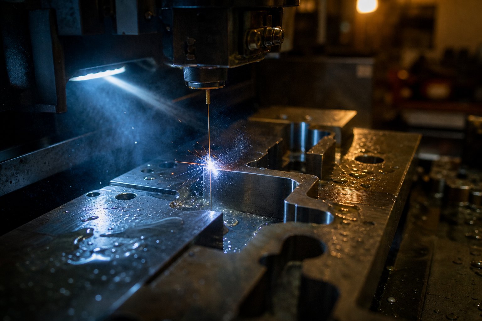
- Wire EDM for precision profiles: Complex die openings, punch profiles, and irregular geometries are cut using wire electrical discharge machining. The wire burns through hardened steel with no mechanical force, producing profiles accurate to 0.0002 in. (5 microns) total with no heat-affected zone distortion.
- Finishing operations: Polishing, lapping, or honing of critical forming surfaces and draw radii. Surface finish directly affects material flow during forming operations.
- Assembly and fitting: Components are assembled into the die shoes. Dowel pin holes are reamed, punches are fitted to retainers, and all clearances are verified against design specifications.
- Die spotting: The assembled die is placed in a spotting press to verify contact patterns and shut heights before moving to a production press.
Wire EDM for stamping die components deserves special emphasis. As KMM Group's technical guidance details, this technology allows designers to produce more compact dies with fewer stations and smaller presses by exploiting the high hoop strength of one-piece die sections. The "punch from die" technique, where the slug from the die opening becomes the punch itself, ensures perfect alignment between mating components. Because wire cutting occurs after heat treatment, there's no metallurgical change at the eroded surface, eliminating distortion that would compromise the clearances you worked so hard to calculate.
Designing specifically for wire EDM requires attention to starting hole placement, minimum corner radii (achievable down to 0.002 in./50.8 microns with fine wire), and taper relief angles. A general tolerance of plus or minus 0.0005 in. (12.7 microns) is standard, with tighter values achievable through skim cuts at additional cost. These capabilities make wire EDM indispensable for die metal stamping where profile accuracy directly controls part quality.
Press Specifications That Constrain Die Design
Here's something apprentice designers learn the hard way: the press isn't a generic force source. Its physical dimensions and mechanical characteristics impose hard boundaries on every die design decision, and those constraints must be addressed from day one, not discovered during installation.
Four press specifications shape die design most directly:
- Tonnage capacity: The total cutting and forming force calculated during design must fall below the press's rated capacity, typically with a 20-30% safety margin. Exceeding capacity risks press frame damage, die cracking, and dangerous overload conditions.
- Bed size: The die's footprint (shoe dimensions) must physically fit within the press bolster. For transfer dies, the bed must accommodate all stations plus clearance for transfer fingers and scrap removal.
- Stroke length: The ram's total vertical travel must exceed the die's open height requirement. This means enough clearance to feed material, lift formed parts, and retract all punches without interference. Short strokes limit forming depth and strip lift height.
- Shut height: The distance from the bolster surface to the ram face at bottom dead center. The assembled die's closed height must match the press's shut height range (adjustable within limits). A die designed too tall or too short for the available press simply won't run.
Transfer die design introduces additional constraints. As noted in The Fabricator's coverage of transfer operations, designers must account for transfer system pitch length (minimum and maximum), clamp length, lift height, and the return path of transfer fingers during the press downstroke. If the number of required stations multiplied by pitch length exceeds the press bed capacity, the project needs a larger press or a fundamentally different manufacturing approach.
Experienced die designers request complete press specifications before drawing a single line. Tonnage, bed size, stroke, shut height, strokes per minute, scrap opening locations, window dimensions for coil feeding: all of these feed into the design as fixed parameters rather than afterthoughts.
Die Tryout and the Art of Practical Adjustment
Die tryout is where theoretical design meets real material behavior, and the two rarely agree perfectly on the first attempt. Even with forming simulation software, variables like friction, press deflection, heat buildup, and actual material properties (versus nominal specs) create gaps between predicted and observed results.
The die tryout and adjustment procedure typically follows this pattern: the assembled die goes into the tryout press, initial hits are made at reduced tonnage and speed, and the resulting parts are measured against specifications. Deviations from target trigger a diagnostic process that works backward from symptom to cause.
Die spotting and blue-matching are foundational techniques in this phase. The diemaker applies a thin layer of engineer's bluing (Prussian blue) to forming surfaces, closes the die on material, and examines the resulting contact pattern. Areas showing heavy blue transfer indicate high spots bearing excessive pressure. Areas with no transfer reveal low spots where the die isn't contacting the material. The diemaker then hand-fits these surfaces, relieving high spots and building up low areas until the contact pattern is uniform across all forming regions.
Springback compensation is frequently the largest tryout challenge for bending and forming stations. Art Hedrick, a veteran die scientist, emphasizes that designers should focus on springback prevention rather than correction, and that significant changes in strain severity cause parts to twist and tip. During tryout, if a flanged part springs open beyond tolerance, the correction might involve increasing the overbend angle, adding a restrike station, or modifying draw bead geometry to redistribute strain more evenly.
Material flow adjustments represent another common tryout resolution. For drawing operations, the diemaker compares actual draw-in measurements around the blank perimeter against simulation predictions. If the formability report shows 35 mm of inward flow in a given area but the die produces only 30 mm, the tool needs modification to achieve that additional 5 mm of flow, whether through radius changes, draw bead alteration, or blank holder pressure adjustment.
Three practical strategies reduce tryout duration significantly:
- Use actual material for tryout: Have the tryout stock tensile-tested to confirm its mechanical properties match simulation inputs. Discrepancies between nominal and actual properties explain most first-hit surprises.
- Create a formability report: Document simulation parameters including friction coefficients, holding pressures, blank dimensions, and predicted draw-in measurements so the tryout technician has concrete targets to match.
- Control metal flow with geometry, not force: Draw beads and radii provide consistent, repeatable flow control. Relying solely on blank holder pressure to restrict material creates sensitivity to material variation and process instability.
A die that exits tryout producing good parts is ready for production validation. But "ready for production" doesn't mean "runs forever without attention." The forces, temperatures, and repetitive cycling that produce parts also produce wear, and managing that wear is what separates a die that runs profitably for years from one that becomes a chronic maintenance headache within months.
Die Maintenance and Troubleshooting Production Problems
A die that exits tryout running clean parts has proven its design. Whether it still runs clean after 500,000 hits depends entirely on maintenance discipline. Poorly maintained tooling doesn't just produce bad parts; it damages presses, injures operators, and turns a six-figure tooling investment into a recurring cost center. The difference between a stamping die maintenance schedule that works and one that exists only on paper is measured in scrap rates, unplanned downtime, and per-part cost.
Here's the uncomfortable truth: most shops labeled "die maintenance" actually run die repair programs. As stamping die expert Art Hedrick points out, if your daily activities include fixing broken pads, welding damaged sections after dowels fall out, or digging crashed parts from draw dies, that's repair, not maintenance. True preventive maintenance addresses items that need regular attention regardless of how well the die was engineered.
Preventive Maintenance Schedules for Production Dies
A functional maintenance program runs on defined intervals tied to stroke counts rather than calendar dates. A die running 200 strokes per minute accumulates wear far faster than one cycling at 40 SPM, so time-based schedules miss the point entirely. Track hits, and build your inspection and service milestones around actual production volume.
Every die returning from production should pass through these inspection checkpoints before going back on the shelf:
- Check all fasteners for tightness; look for loose or missing dowel pins that could allow section shifting.
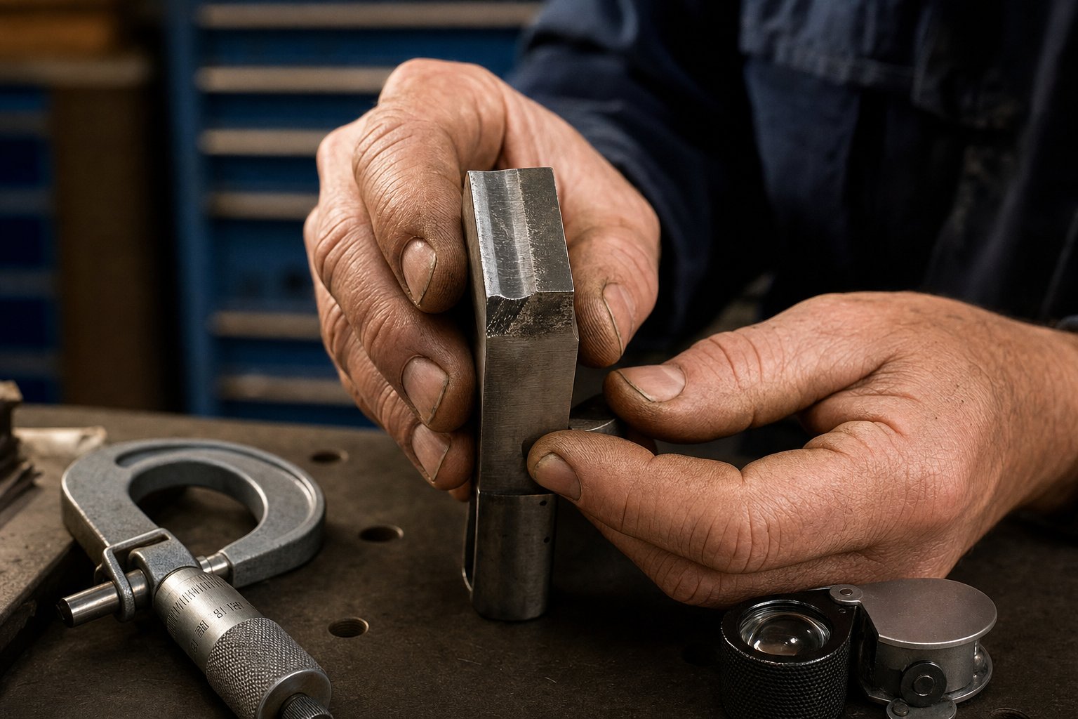
- Inspect cutting edges for chipping, dulling, or cracking. Measure burr height on the last parts produced to assess sharpening urgency.
- Examine springs for fatigue cracks or set (permanent compression). Replace any springs approaching the end of their rated cycle life.
- Inspect wear plates, cam surfaces, and forming radii for galling or material pickup. Regrind and refit as necessary.
- Clean all debris including slugs, slivers, and lubricant buildup from every cavity and clearance hole.
- Lubricate all mating die surfaces, guide pins, and cam mechanisms.
- Verify all safety guards are in place and functional.
- Dry the die thoroughly to prevent rust formation during storage.
- Confirm all cutting punches are secure in their retainers with no rotational looseness.
Sharpening intervals vary by material and production demands, but a practical guideline is to sharpen before burrs exceed the part's maximum allowable specification. Waiting until operators complain means the die has already been producing marginal or rejectable parts for some time. Proactive sharpening, triggered by stroke count targets validated against historical burr measurement data, keeps parts in spec consistently.
When sharpening, grinding wheel selection matters more than most shops realize. Tool steels like D2 and powdered metals contain hard carbide pools that resist conventional wheels. A wheel that loads up instead of breaking down freely generates excessive heat, which can soften, heat-check, or crack the very section you're trying to restore. Use flood coolant, consult your abrasives supplier for material-matched wheels, and grind shear angles that balance cutting forces across the die section to maintain punch-to-button alignment.
Troubleshooting Burrs and Dimensional Drift
When parts start failing inspection, the symptom points toward the cause if you know how to read it. Troubleshooting burr formation in stamping, for example, almost always traces back to clearance degradation. Punches and buttons wear progressively, increasing the effective gap between them. That growing gap means the material rolls further into the clearance zone before fracturing, producing heavier burrs on each successive hit.
Dimensional drift tells a different story. When hole locations or profile dimensions shift gradually over a production run, the root cause is typically wear-induced misalignment: guide pins loosening, die sections shifting on worn dowels, or punch retainers losing grip. Sudden dimensional shifts, by contrast, suggest a mechanical failure such as a broken dowel, cracked die section, or displaced shim stack.
Slug pulling causes and solutions deserve particular attention because a single pulled slug carried through a progressive die can damage every downstream station in one stroke. Slugs stick to punch faces due to vacuum pockets created by slug curvature, large cutting clearances that eliminate the press-fit retention effect, magnetized punches from surface grinding, or fatigued spring ejectors that no longer push the slug free. Effective countermeasures include venting small air holes through punch centers to break vacuum, using reverse-taper die buttons that hold slugs in compression, installing spring-loaded ejectors, demagnetizing all components after grinding, and reducing lubricant viscosity in problem areas.
The following table maps the most common production symptoms to their likely root causes and corrective actions:
| Symptom | Likely Root Cause | Corrective Action |
|---|---|---|
| Excessive or growing burrs | Punch/button wear increasing effective clearance | Sharpen cutting edges; verify clearance and reset if beyond tolerance |
| Burrs on one side only | Punch-to-die misalignment (guide wear, loose sections) | Check guide pins/bushings for wear; inspect dowels and retighten die sections |
| Gradual dimensional drift | Wear on guide components, pilot pins, or locating features | Replace worn pilots; rebush guides; verify strip registration accuracy |
| Sudden dimensional shift | Broken dowel, cracked section, or displaced component | Disassemble and inspect; replace failed components; verify die shut height |
| Slug pulling onto strip | Vacuum, excessive clearance, magnetism, or weak ejectors | Vent punches; install retention buttons; demagnetize; replace ejector springs |
| Premature punch breakage | Excessive shear load, misalignment, insufficient backing, or incorrect steel grade | Verify alignment; check backing plate hardness; evaluate steel selection; add shear angle |
| Strip misfeed or buckle | Weak or broken lifter springs; debris in feed path; incorrect feed release timing | Replace lifter springs; clean die; adjust press feed timing and release angle |
The diagnostic approach is straightforward: observe the symptom, identify whether it appeared gradually or suddenly, locate where on the part or strip the defect occurs, and trace backward from that location to the responsible die component. Gradual onset means wear. Sudden onset means failure. Location on the part points directly to the station or component involved.
Extending Die Life Through Design and Surface Treatment
Reactive maintenance keeps a die running. Proactive strategies extend the interval between each service, improving how to extend stamping die life far beyond baseline expectations. Three approaches deliver measurable results:
Surface treatments and coatings add a wear-resistant barrier without changing component geometry. PVD (Physical Vapor Deposition) coatings deposit ultra-thin films (typically 1-5 microns) of materials like TiN, TiCN, or AlTiN onto hardened die components. These coatings improve surface hardness to 3000+ HV, reduce friction and galling, and resist thermal degradation. Because the films are conformal and extremely thin, they don't affect dimensional tolerances or punch-to-die clearances. AlTiN-based coatings are particularly effective for progressive die punches working high-strength steel, while TiCN reduces adhesive wear and material pickup in forming stations. Many shops recoat punches and buttons after each regrind cycle to restore wear resistance at minimal cost.
Design modifications that reduce stress concentration extend component life at the source. Adding larger radii to punch shoulders, incorporating proper shear angles to reduce peak cutting force, and specifying adequate cross-sectional thickness for thin punches all prevent the conditions that cause premature failure. Sometimes the longest-lasting fix for a chronic breakage problem isn't better steel or more frequent sharpening. It's redesigning the component to eliminate the stress riser that keeps causing it.
Material upgrades for chronic wear stations shift the economics. Replacing a D2 punch that needs sharpening every 50,000 hits with a carbide-inserted version lasting 500,000 hits costs more upfront but eliminates nine sharpening cycles and the associated downtime. The decision comes down to production volume: high-volume programs justify premium materials because the per-part maintenance cost drops even as the tooling investment rises.
Maintenance discipline, troubleshooting skill, and life-extension strategies together determine whether a stamping die delivers its designed ROI or drains resources throughout its production life. These capabilities also reveal a great deal about the organizations that build and support stamping tooling, which is precisely what matters when evaluating a die design partner for complex, high-volume programs.
Choosing a Die Design Partner for Complex Stamping Projects
Maintaining a die in production is one challenge. Designing and building it correctly in the first place is another, and for complex programs with tight tolerances, multi-station progressive layouts, or demanding material flow requirements, that challenge often exceeds what a single engineering team can handle alone. Knowing how to choose a die design partner becomes as important as knowing die design itself.
Evaluating a Die Design Partner for Complex Projects
A competent die shop can machine components to print. An exceptional one questions the print before cutting steel. The difference shows up in tooling that runs at speed without chronic adjustment versus tooling that works on paper but fights you in production. What separates the two?
Look for partners who demonstrate genuine depth in these areas:
- Die structure expertise: Can they explain why they chose a specific stripper configuration, lifter height, or bypass notch geometry for your application? Partners who default to the same die architecture regardless of part complexity are a red flag.
- Clearance and burr control mastery: Do they optimize punch-to-die clearance based on your actual material, thickness, and edge quality requirements, or do they apply a generic percentage across the board?
- Material flow problem-solving: For forming and drawing stations, can they demonstrate experience managing draw-in, controlling wrinkle tendency, and compensating for springback through geometry rather than brute force?
- In-house toolmaking capability: Suppliers with in-house engineering and toolmaking can iterate faster, maintain tighter communication between design intent and shop-floor execution, and resolve tryout issues without handoff delays between separate organizations.
- Collaborative design iteration: The best partners treat your engineering team as collaborators, not order-takers. They push back on features that will cause production headaches, suggest alternatives that reduce cost, and share simulation results before committing to steel.
- Proven industry experience: Ask for specific examples of dies they have built for similar part geometries, materials, and volumes. Experience with your application type, whether automotive structural, electrical connector, or appliance housing, reduces the learning curve that otherwise plays out during your tryout.
Key Capabilities to Look for in Custom Die Solutions
Complex stamping die engineering services go beyond building what you specify. The real value appears when a partner identifies problems you haven't seen yet: a strip layout that wastes material, a station sequence that creates unnecessary stress on carrier webs, or a forming radius that will generate splits in production material that's harder than the nominal spec.
When evaluating custom stamping die solutions, prioritize suppliers who offer end-to-end support from concept through production validation. YICHEN exemplifies this model, connecting tooling engineers to design-heavy expertise covering die structure, component specification, punch and lifter design, bypass notch geometry, burr control optimization, and material flow engineering. Their focus on the engineering-intensive aspects of die development makes them a strong fit for programs where standard catalog tooling falls short and custom problem-solving drives the outcome.
Beyond any single supplier, use these die supplier evaluation criteria as a practical checklist before committing to a partnership:
- Request references from projects with comparable complexity, material, and volume requirements.
- Ask about their tryout process: do they run first-off parts on their own presses before shipping, or does your production press become the tryout platform?
- Confirm quality equipment and facilities including wire EDM, CNC machining centers, surface grinding, and in-house heat treatment or qualified heat treatment partners.
- Evaluate responsiveness during the quoting phase. A partner slow to respond before they have your money rarely speeds up after.
- Verify whether they offer ongoing die maintenance support or lifetime service agreements that protect your tooling investment after production launch.
The disciplines covered throughout this guide, from clearance calculations and strip layout optimization to tryout adjustment and preventive maintenance, represent the knowledge base your die partner should demonstrate fluently. A supplier who understands these principles deeply will build tooling that runs longer between service intervals, produces cleaner parts from first hit, and adapts more gracefully when material or volume requirements shift mid-program. That's the return on choosing a partner rather than just a vendor.
Sheet Metal Stamping Dies Die Design and Die Making Practice FAQ
1. What is the difference between a progressive die and a compound die?
A compound die performs multiple cutting operations simultaneously in a single station during one press stroke, producing flat parts with excellent hole-to-edge accuracy. A progressive die uses multiple stations arranged in sequence, with the strip advancing one pitch per stroke so each cycle works on several parts at different stages of completion. Progressive dies handle greater part complexity including combined cutting, bending, and forming, while compound dies offer lower tooling cost and better part flatness for simpler geometries. Choose compound tooling for medium-volume flat parts needing tight positional tolerances, and progressive tooling for high-volume multi-feature parts requiring automated coil feeding.
2. How do you calculate punch-to-die clearance for sheet metal stamping?
Punch-to-die clearance is calculated as a percentage of material thickness per side. The standard starting point is roughly 10% per side, though modern practice often uses 11-20% to reduce tooling strain and extend die life. The procedure involves identifying the workpiece material, confirming stock thickness, looking up the recommended clearance percentage from engineering reference tables based on material type and tensile strength, then multiplying thickness by that percentage to get per-side clearance. For blanking, the die opening matches desired blank size while the punch is undersized by twice the clearance. For hole punching, the punch matches desired hole size while the die opening is oversized by twice the clearance. Harder materials require wider clearance, while softer materials and precision work call for tighter gaps.
3. What causes burr formation in stamping dies and how do you fix it?
Burr formation primarily results from degraded punch-to-die clearance caused by progressive edge wear. As punches and buttons wear, the effective gap between them increases, allowing material to roll further into the clearance zone before fracturing, which produces heavier burrs with each successive hit. One-sided burrs indicate punch-to-die misalignment from worn guide pins or loose die sections. Corrective actions include sharpening cutting edges before burrs exceed the part's allowable specification, verifying and resetting clearance if it has drifted beyond tolerance, checking guide pins and bushings for wear, and inspecting dowels to ensure die sections remain properly located. Proactive sharpening triggered by stroke count targets rather than visual inspection prevents extended runs of marginal parts.
4. What tool steel is best for stamping die punches and buttons?
The best tool steel depends on the specific application. D2 (high-carbon high-chromium) dominates high-volume blanking and piercing because it offers superior abrasion resistance and dimensional stability after heat treatment. A2 (air-hardening) provides better toughness than D2, making it preferable where impact shock or thin cross-sections create chipping risk, such as forming punches under dynamic loads. M2 (high-speed steel) retains hardness at elevated temperatures, an advantage in fast-cycling progressive dies where frictional heat would soften conventional cold-work steels. For stations stamping abrasive materials like stainless steel or silicon steel laminations, tungsten carbide inserts deliver extreme wear life measured in millions of additional hits. Powder metallurgy variants of these grades offer improved toughness and wear resistance simultaneously through refined carbide structures.
5. How do you choose a reliable die design partner for complex stamping projects?
Evaluate potential partners on die structure expertise, clearance and burr control mastery, material flow problem-solving capability, and in-house toolmaking capacity. A strong partner questions your design before cutting steel, optimizes clearance based on actual material and edge quality requirements rather than generic percentages, and demonstrates experience managing draw-in and springback through geometry. Providers like YICHEN specialize in design-heavy stamping die challenges covering die structure, component specification, lifter design, bypass notch geometry, and material flow engineering. Key evaluation criteria include requesting references from comparable projects, confirming whether they run first-off parts on their own presses, verifying quality equipment such as wire EDM and CNC machining, and assessing responsiveness during the quoting phase.


