


What Stamping Die Parts Are and Why They Matter
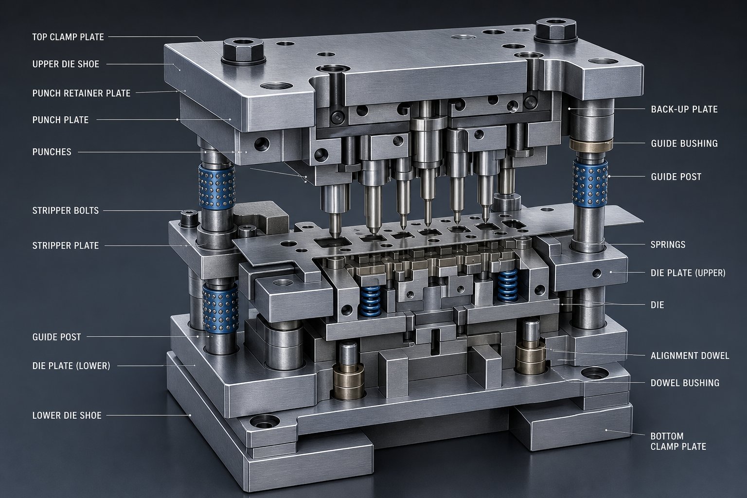
Stamping die parts are the individual precision components inside a stamping die that work together to cut, form, and shape sheet metal into finished parts. A stamping die itself is a custom-engineered tool assembly mounted in a press, but its real capability comes from dozens of interdependent elements, each responsible for a specific mechanical function during every press stroke. From the structural shoes that absorb tonnage to the pilot pins that register strip position within thousandths of an inch, every component plays a defined role in determining whether your stamped parts come out clean or defective.
What Is a Stamping Die and What Are Its Parts
So what is a die in the context of metal stamping? It is the specialized tooling used within a power press to apply controlled force that cuts, bends, draws, or pierces raw sheet metal into a finished component. Think of it as two halves, upper and lower, that close together under enormous pressure. The upper half mounts to the press ram, the lower half bolts to the press bed, and between them sits a precisely engineered system of cutting edges, forming surfaces, guides, springs, and strippers.
Here is where terminology gets important. When engineers say "the die," they might mean the entire tool assembly or they might mean a specific cutting insert. A die is used to execute one or more operations on sheet metal, but the tool itself is built from many discrete parts, each with its own material specification, tolerance, and wear pattern. Understanding what is a die used for at the system level versus what each internal component contributes individually is the difference between reactive maintenance and proactive tooling management.
For tooling engineers and die designers, knowing every part's function means faster root-cause analysis when quality drifts. For maintenance teams, it means replacing the right component at the right interval instead of chasing symptoms. What is die tool knowledge worth? It is the foundation for reducing scrap, extending tool life, and keeping presses running.
Why a Systems-Level Understanding Matters
Most references treat stamping dies as a flat parts list. You get a name, a picture, maybe a sentence about function. That approach misses the point. These components do not operate in isolation. A worn guide bushing affects punch-to-die alignment, which changes cutting clearance, which creates burrs, which triggers premature punch regrinding. One degraded part cascades into system-wide quality loss.
This guide takes a different approach. Instead of listing what are dies made of piece by piece, it groups every component by its functional role and shows how those roles interconnect across the press stroke. The result is a systems-level framework that helps you diagnose problems faster and specify components smarter.
Here are the six functional categories covered in this guide:
- Structural components - Die shoes, plates, and parallels that form the rigid foundation and absorb press tonnage.
- Cutting and piercing components - Punches, die buttons, and inserts that shear sheet metal into specific geometries.
- Forming and bending components - Forming punches, wipe steels, and draw pads that plastically deform material without removal.
- Guiding and alignment components - Guide pins, bushings, pilots, and stock guides that maintain repeatable positioning.
- Stripping and lifting components - Strippers, lifters, and bypass notches that manage strip movement and part ejection.
- Springing and force components - Nitrogen cylinders, urethane, and coil springs that deliver controlled reactive forces throughout the stroke.
Each category feeds directly into the next. Structural integrity enables accurate guiding. Accurate guiding preserves cutting clearance. Proper clearance reduces stripping loads. And adequate stripping force keeps material flowing reliably through every station. That interdependence is exactly why a single worn component can quietly degrade your entire stamping operation, and why understanding the full system is what separates high-performing toolrooms from those stuck in reactive repair cycles.
Structural Components That Form the Die Foundation
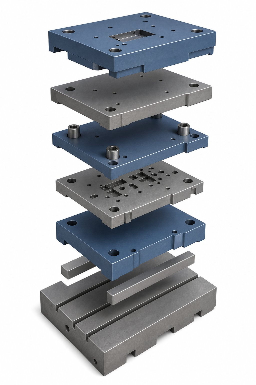
Every functional category in a stamping die depends on one thing first: a rigid, stable platform that holds everything in alignment under repeated high-tonnage impacts. Without that foundation, cutting clearances shift, forming geometry distorts, and guide systems wear prematurely. The structural components are the quiet workhorses of the die assembly. They rarely get attention until something deflects, cracks, or walks out of position, and by then you are already scrapping parts.
Die Shoes and Their Role as the Structural Backbone
Imagine bolting a precision cutting tool to a platform that flexes every time the press cycles. That is exactly what happens when a die shoe is undersized or made from the wrong material. Upper and lower die shoes serve as the mounting surfaces for every other component in the tool. The upper shoe attaches to the press ram, the lower shoe bolts to the press bed or bolster plate, and together they carry the full stamping load across the entire stroke.
Material choice matters here. Cast iron shoes offer good vibration damping and are cost-effective for lighter-duty applications, while steel shoes deliver higher rigidity and resistance to deflection under heavier press tonnage. You will find most metal stamping die sets specified with steel shoes when tonnage exceeds moderate levels or when tight tolerances demand minimal flex across the tool footprint.
Shoe thickness is directly tied to press tonnage and span. A thin shoe bridging a wide press bed will bow at center, pulling guide pins out of alignment and opening up clearance unevenly across cutting stations. Die designers calculate minimum shoe thickness based on load distribution, unsupported span, and acceptable deflection limits, typically holding flex well below the point where it would affect punch-to-die clearance.
Standard catalog die shoe sizes cover common press bed dimensions and bolt patterns, making them a practical choice for general-purpose tooling. Custom-machined shoes become necessary when the press has non-standard mounting, when the die footprint is irregular, or when weight reduction is critical for handling and setup. Either way, the die shoe is the structural starting point that every other component depends on.
Die Plates, Backing Plates, and Retainer Systems
Mounted on top of those shoes sits a stack of precision-machined plates, each with a specific structural role. The die plate is where the actual cutting and forming geometry lives. It contains the pockets, apertures, and profiled edges that define the female half of every operation. Because it absorbs direct cutting forces on every stroke, the die plate is typically machined from tool steel and hardened to resist wear.
Directly behind the punch tips sits the backing plate. Its job is simple but critical: distribute concentrated punch loads across a broader area of the shoe to prevent mushrooming, which is the gradual peening of soft shoe material under repeated point loads. Without a hardened backing plate, punch heads slowly sink into the shoe surface, changing shut height and degrading cut quality over thousands of hits.
Retainer plates hold punches, pilots, and other working details in fixed position. They use precision-bored holes matched to punch shanks, often combined with ball-lock, keyed, or head-retention methods that allow quick replacement without disassembling the entire upper half. As Moeller Precision Tool notes, well-designed retainers reduce die assembly time and help eliminate stacking tolerance errors that accumulate when multiple plates are involved.
These plates are stacked and pinned together using hardened dowel pins that lock their relative positions. Once doweled, the plate stack can be disassembled for maintenance and reassembled to the same alignment every time. That repeatability is what makes a stamping die set reliable across hundreds of thousands of press cycles rather than just the first hundred.
Parallels, Risers, and Spacer Blocks
Beneath the lower die plate, you will find parallels: hardened steel bars that elevate the die block off the bolster surface. Why does that gap matter? Scrap slugs and finished parts need somewhere to go. Without adequate clearance below the cutting stations, slugs stack up inside die openings, jam the tool, and cause catastrophic crashes. Parallels create that exit path while also supporting the lower shoe evenly across the press bed.
Risers serve a different purpose. In progressive dies with multiple stations, different operations may need to sit at different elevations relative to the strip line. Risers elevate specific stations or detail areas to match the required working height, particularly when formed features at one station must clear tooling at subsequent stations as the strip advances.
Spacer blocks and stop blocks round out the structural system. Spacer blocks set precise shut heights between die halves, while stop blocks act as hard mechanical limits that prevent over-travel during a press crash, protecting delicate cutting and forming details from catastrophic damage.
Specifying any of these structural components comes back to three constraints: press bed size determines footprint and parallel spacing, shut height determines overall stack-up thickness, and feed direction dictates where clearance channels must be located for scrap evacuation.
| Structural Component | Primary Function | Typical Material | Common Thickness Range |
|---|---|---|---|
| Upper/Lower Die Shoes | Mount all components, absorb press tonnage | Cast iron or steel | 25 mm - 100 mm+ |
| Die Plate | Contains cutting/forming geometry | Tool steel (hardened) | 19 mm - 50 mm |
| Backing Plate | Distributes punch loads, prevents mushrooming | Hardened steel | 6 mm - 19 mm |
| Retainer Plate | Holds punches and pilots in position | Alloy steel or tool steel | 19 mm - 38 mm |
| Parallels | Creates scrap clearance below the die | Hardened steel | 38 mm - 75 mm height |
| Risers/Spacer Blocks | Elevates stations, sets shut height | Steel | Application-dependent |
| Stop Blocks | Prevents over-travel during crash events | Steel | Matched to die web height |
Structural components rarely wear in the dramatic way that punches or die buttons do. Their failure mode is more subtle: gradual deflection, loosening dowels, worn bolt holes, and surface peening that slowly shifts alignment across the entire tool. That quiet degradation is exactly what makes them worth monitoring, because by the time a structural problem shows up in your stamped parts, it has already been affecting every cutting and forming station in the die for thousands of strokes. And those cutting stations, with their punches, die buttons, and clearance relationships, are where part quality is directly won or lost.
Cutting and Piercing Components That Shape the Blank
Structural rigidity keeps everything aligned, but alignment only matters because of what happens at the cutting edge. The punches and die buttons inside a stamping tool are the components that actually contact the sheet metal and shear it into a defined geometry. Every hole, notch, slot, and blank outline exists because a hardened punch drove through the material and into a precisely matched opening below. Get these die cut components right, and you produce clean edges at high speed. Get them wrong, and you fight burrs, broken punches, and dimensional drift from the first hit.
Punch Types and Their Cutting Functions
When you look inside a progressive or compound die, you will notice multiple stamping die punches, each ground to a specific profile that determines the cut it produces. Here are the most common styles:
- Piercing punches - Create internal holes by driving a slug completely through the material. Round, oblong, or shaped profiles are all common.
- Blanking punches - Cut the full outer perimeter of a finished part. The slug becomes the workpiece rather than scrap.
- Notching punches - Remove material from the strip edge, cutting on only one side. Because force is unbalanced, these require a heel block opposite the cutting edge to resist lateral deflection.
- Trim punches - Shear excess material or carrier tabs away from a nearly finished part, typically in the final station of a progressive die.
Geometry defines what the punch cuts, but retention method defines how it stays in the tool. Head-type punches seat into a counterbored pocket in the retainer plate, held in place by a backing plate above. Ball-lock punches snap into a quick-change retainer, allowing replacement without disassembling the upper die half. Keyed punches use a flat or groove that prevents rotation, critical for non-round profiles where angular orientation matters.
Off-the-shelf catalog punches cover standard round and simple shapes in common sizes. When your part geometry calls for irregular profiles, tight tolerances, or unusual materials, custom-ground punches become necessary. These are typically wire-EDM cut or precision-ground to match the exact feature required.
Die Buttons, Die Inserts, and Cutting Edges
Every sheet metal punch and die pair works as a matched system. The punch provides the male cutting profile, and the die button provides the female opening that receives it. Die buttons are hardened, precision-bored cylinders pressed into the die plate. Their internal geometry defines the exact size of the hole or blank produced, and their edge condition directly determines cut quality.
For standard round holes, conventional grinding produces die buttons with sufficient accuracy for most applications. When tolerances tighten below a few thousandths of an inch, or when the profile includes sharp internal corners and intricate shapes, wire-EDM machining becomes the preferred method. Wire EDM achieves tolerances of +/-0.0001 to +/-0.0003 inches and can produce internal radii as small as 0.0005 inches, making it ideal for creating the complex die button geometries that progressive dies demand.
Sectional die inserts take this concept further. Rather than machining complex cutting geometry directly into the die plate, engineers fit individual hardened inserts into pockets within the plate. When an edge wears or chips, you replace that single insert instead of reworking or scrapping the entire plate. This modular approach reduces maintenance cost and downtime significantly, especially in high-volume production where localized wear is inevitable.
How Punch-to-Die Relationships Determine Cut Quality
Metal punches and die openings do not work independently. They function as a matched pair separated by a carefully controlled gap called cutting clearance. This gap, expressed as a percentage of material thickness per side, is the single most influential variable in determining edge quality, burr height, and tool life.
When clearance is correct, the fracture lines initiated by the punch and the die opening meet cleanly in the middle of the material thickness. The result is a cut edge with a predictable ratio of burnish (the smooth, sheared portion) to fracture (the rougher break zone). For low-carbon steel with proper clearance, this follows roughly a one-third shear, two-thirds break pattern, as MetalForming Magazine explains in its analysis of the relationship between material properties and clearance selection.
When clearance is too tight, the punch must force its way through more material before fracture occurs. This increases cutting forces, generates more heat, accelerates punch wear, and can produce a secondary shear or double-break edge condition. When clearance is too loose, the material rolls into the opening before fracturing, producing excessive burrs and large rollover zones.
The real challenge? Clearance is not universal. Higher-strength materials fracture earlier and typically need more clearance, while softer materials can tolerate tighter gaps. Relying on a single clearance value for every material, a common shop-floor habit, guarantees suboptimal results on at least some of your dies and punches. Detailed clearance guidance by material type follows later in this guide.
Beyond clearance, sheet metal punches and dies fail in predictable patterns. Recognizing these failure modes early helps maintenance teams intervene before part quality degrades:
- Edge chipping - The most frequent failure, caused by excessive snap-through shock, insufficient clearance, or lateral deflection from misalignment.
- Abrasive wear - Gradual dulling of the cutting edge from friction against the workpiece, accelerated by abrasive materials like stainless steel and AHSS grades.
- Galling and material pickup - Workpiece material welds to the punch face under heat and pressure, common with aluminum and stainless steel.
- Head breakage - The punch head shears off inside the retainer due to snap-through shock or improper seating against the backing plate.
- Lateral deflection and bending - Slender punches bow under off-center loads, especially in notching operations without adequate heel support.
Each failure mode traces back to a specific root cause in clearance, alignment, material choice, or retention method. The cutting system lives or dies by how precisely these variables are controlled, and the moment a punch engages the strip, the accuracy of every guiding component in the die determines whether that engagement happens where it should.
Forming and Bending Components for Plastic Deformation
Cutting removes material. Forming reshapes it. While punches and die buttons shear sheet metal into flat profiles, forming and bending components take those profiles and plastically deform them into three-dimensional features without removing any material at all. Bends, draws, embosses, lances, ribs, and flanges all come from this category of metal stamping dies, and the components responsible for producing them face an entirely different set of engineering challenges than their cutting counterparts.
Where cutting demands sharpness and clearance control, forming demands precise geometry, controlled material flow, and carefully calibrated reactive pressure. Get the balance right and your parts come out wrinkle-free with consistent dimensional accuracy. Get it wrong and you are fighting splits, springback, and surface defects that no amount of downstream correction can fix.
Forming Punches, Bending Steels, and Wipe Dies
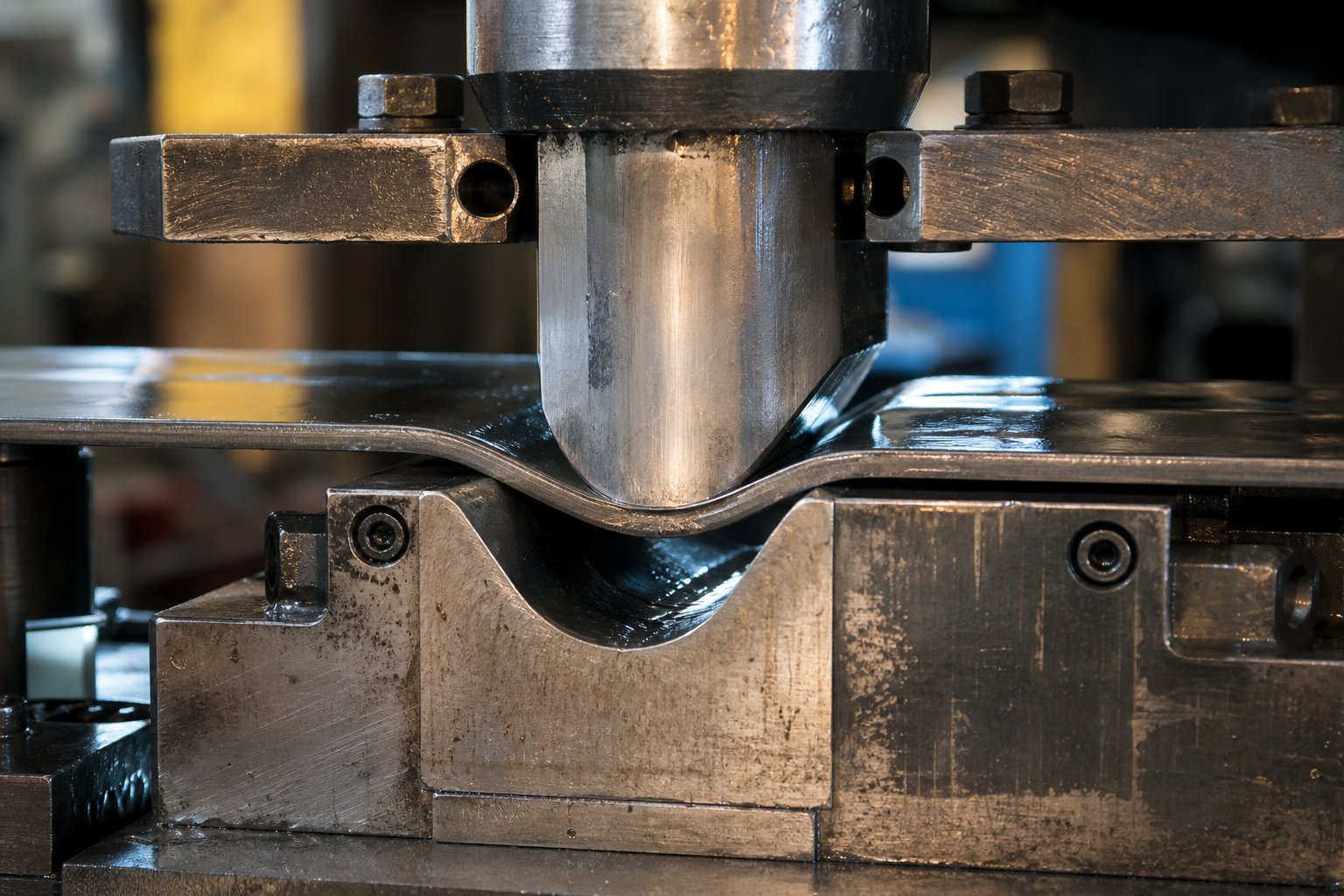
Forming punches work by pushing sheet metal into a female cavity or over a hardened edge, forcing the material to yield and permanently take a new shape. Unlike piercing punches that cut cleanly through the strip, forming punches contact a broad surface area and apply force over a longer portion of the press stroke. They produce bends, drawn cups, embossed features, and lanced tabs depending on their geometry and the corresponding female tooling below.
Bending steels and wipe dies create angular bends by wiping the material over a fixed edge or into a V-shaped pocket. The method of bending determines how the die components are designed:
- Air bending - The punch pushes the material partway into a V-shaped opening without contacting the bottom. Bend angle depends entirely on punch depth. This requires fewer die pressing tonnage and produces less tool wear, but springback is harder to control.
- Bottoming - The punch forces the material fully against the V-shaped die surface, creating firm contact along the bend legs. This produces higher accuracy and less springback than air bending because the material conforms completely to the die geometry.
- Coining - The punch applies extreme force, up to 30 times greater than air bending, compressing the material at the bend zone until it flows plastically and takes a permanent set. Coining virtually eliminates springback but demands significantly heavier die pressing components and higher press tonnage.
How these forming components are arranged depends on which types of stamping dies you are building. In progressive dies, forming happens incrementally across multiple stations. A shallow pre-bend at one station becomes a full 90-degree flange several stations later, with the strip carrying partially formed features through each subsequent operation. Sheet metal stamping dies configured as transfer tools take a different approach. Because the part is separated from the strip and physically moved between stations, transfer dies can perform complex deep draws in a single hit without worrying about strip continuity. Compound dies, which complete all operations in one stroke, rarely include forming features since their geometry is limited to flat cutting profiles.
This distinction matters for component design. Progressive die forming punches must be shorter and account for strip lift between stations. Transfer die forming punches can be deeper and more aggressive because they are not constrained by strip-feed mechanics. Steel stamping dies designed for high-strength materials also need forming components with larger radii to prevent cracking, since higher-strength sheets tolerate less deformation before fracturing.
Draw Pads, Pressure Pads, and Nitrogen Springs
Forming punches shape the part, but pressure systems control how the material flows during that shaping. This is where draw pads come in. A draw pad, also called a blank holder or pressure pad, is a pressure-loaded plate that surrounds the forming punch and applies controlled hold-down force to the sheet metal as it is drawn into a cavity.
Sounds simple? The reality is more nuanced. As die stamping expert Art Hedrick explains, the true function of a draw pad is not to squeeze the metal and create resistance to flow, but to keep the material from wrinkling during inward flow and compression. Without adequate hold-down pressure, the compressive forces generated as material draws inward cause the flange to buckle into wrinkles. Too much pressure, and the material cannot flow at all, leading to splits at the punch radius.
The force driving these pads comes from one of three spring systems, each with distinct characteristics that make them suitable for different applications:
| Spring Type | Force Range | Life Expectancy | Typical Application |
|---|---|---|---|
| Nitrogen gas springs | High (up to several tons per unit) | 1-3 million cycles with proper maintenance | Deep draws, high-force hold-downs, consistent pressure across stroke |
| Urethane springs | Low to moderate | 100,000-500,000 cycles depending on compression ratio | Strippers, light-duty forming pads, confined spaces |
| Mechanical coil springs | Low to moderate | 500,000-1 million cycles at recommended deflection | General stripping, moderate hold-downs, cost-sensitive applications |
Selecting the right spring system connects directly to material thickness and tensile strength. A 1.5 mm mild steel draw at 270 MPa tensile requires far less hold-down force than a 1.5 mm stainless steel draw at 600 MPa tensile. Nitrogen gas springs are often the only practical option for high-strength materials because they can deliver greater force in a smaller envelope and offer more consistent pressure throughout the stroke compared to mechanical alternatives.
Material type also changes forming component geometry. Aluminum galls aggressively against uncoated tool steel, requiring polished surfaces or anti-galling coatings on forming punches and draw pads. Stainless steel work-hardens rapidly, which means forming radii must be generous enough to prevent cracking on the first hit. Mild steel is the most forgiving, tolerating tighter radii and requiring less hold-down force, which is exactly why it remains the baseline material that all forming component specifications reference first.
The interplay between forming geometry and pressure control is what separates a reliable production die from one that produces inconsistent parts. And that interplay only works when the forming punch engages the material at precisely the right location every single stroke, which is the job of the guiding and alignment system waiting in the next functional layer of the die.
Guiding and Alignment Systems for Precision Registration
Forming punches shape material with controlled force, but force alone means nothing if it lands in the wrong place. Every operation in a stamping die, whether cutting or forming, depends on the upper and lower halves meeting at exactly the same position on every single stroke. A misalignment of just a few thousandths of an inch shifts punch-to-die clearance from optimal to destructive, turning clean cuts into burred edges and shortening tool life dramatically. The stamping die components responsible for preventing that scenario are the guiding and alignment systems, and they work on two distinct levels: aligning the die halves to each other, and aligning the strip material to the tooling.
Guide Pins, Guide Bushings, and Ball-Bearing Cages
Guide pins, also called leader pins, are hardened cylindrical posts mounted in one die half that engage precision-bored bushings in the opposite half. As the press ram descends, these posts slide into their mating bushings and force the upper and lower die into repeatable alignment before any punch contacts the workpiece. Without them, the press slide's inherent clearance to its gibs would allow the upper die to shift laterally during each stroke, producing uneven wear and inconsistent parts.
Two basic types of guide-post and bushing systems are commercially available, as MetalForming Magazine details in its analysis of die set guiding systems:
- Plain-bearing systems - The guide post runs inside a solid bushing, typically bronze-plated steel or solid aluminum bronze, with a small engineered running clearance between the surfaces. Self-lubricating graphite plugs are common in these bushings. Plain-bearing systems handle side loads well because the entire bushing surface supports the post.
- Ball-bearing cage systems - A cage of precision steel balls rides between the post and bushing in a preloaded condition with negative clearance (typically 0.0001 to 0.0021 inches of preload depending on manufacturer and diameter). Rolling contact dramatically reduces friction, making these ideal for high-speed, short-stroke progressive dies.
Fit class selection determines how the post mounts to the die shoe. A press-fit post is permanently installed into the lower shoe and cannot be removed without a hydraulic press. A slip-fit or demountable post allows easier assembly and disassembly, which simplifies maintenance on long progressive dies that must be partially broken down for regrinding operations.
One critical design principle often overlooked: the guide bushing should engage the guide post at the working level of the die whenever possible. This loads the post in shear, its strongest condition, and prevents bending moments that cause deflection. Placing the bushing high in the upper shoe out of convenience introduces a moment arm that allows the post to flex under load, degrading the very alignment it was designed to maintain. The guide post should also bypass the end of the bushing with the die closed, ensuring uniform wear along the entire bushing length.
Ball-bearing systems introduce a tradeoff. While they reduce friction and excel at speed, they are vulnerable to side-loading. Excessive lateral forces during forming or notching operations push individual balls into point-contact stress, and over time those balls dig tracking marks into the post or bushing surfaces. Tracking lines visible on one side of the guide post are a clear indicator that the die is generating higher side loads than the ball-bearing system was designed to absorb.
Pilot Pins and Stock Guides for Strip Control
Guide pins align the die halves, but what aligns the strip to the die? In a progressive die, the material moves through multiple stations, and at each station it must be positioned to within thousandths of an inch of its intended location. Pilot pins handle that registration by engaging previously pierced holes in the strip and pulling the material into precise position before any cutting or forming begins at that station.
Imagine the sequence: the feeder advances the strip one pitch length, pilot pin tips enter the holes first to provide initial guidance, then the locating diameters engage and draw the strip into true position. Pilots are typically sized with 0.0005 to 0.001 inches of clearance to the pilot holes, depending on material type and thickness. Too much clearance allows the strip to wander. Too little clearance causes the pilots to drag and elongate the holes over time.
Pilot length is equally critical. As Peter Ulintz explains, pilots must be long enough to enter the pilot hole before other punches engage and the stripper contacts the lower die, but short enough that they do not bind or pull the strip upward when the die opens. Getting this balance wrong creates progression errors that worsen at production speed.
Feed-roll timing ties directly into pilot function. The correct sequence requires the feed roll to lift (release the strip) before the pilot locating diameters enter the holes. If the roll still grips the strip when pilots engage, the feeder fights the pilots, bending them, elongating pilot holes, and introducing unpredictable strip shifts. This timing window can be extremely narrow, especially on dies with stock lifters where the feed roll must remain open until lifters reach full travel.
Beyond pilots, several other tooling components constrain the strip laterally and longitudinally:
- Stock guides - Channel-shaped rails mounted on the die plate that constrain the strip's side-to-side movement as it feeds through the die.
- Tunnel guides - Enclosed guides that capture the strip on both sides and top, preventing it from lifting or shifting in areas between stations.
- Heel blocks - Hardened steel blocks positioned along the die perimeter that absorb lateral thrust from unbalanced cutting or forming operations, preventing the entire upper die from shifting relative to the lower.
- Finger stops - Mechanical stops that engage the strip edge or a notch to control feed length in manually fed dies.
- Automatic stock stops - Spring-loaded or cam-actuated stops that precisely limit strip advance in power-fed applications, providing a secondary feed-length control behind the electronic feeder.
Timing and Alignment Across Die Types
Guiding requirements shift substantially depending on the type of stamping die in operation. A progressive die must maintain continuous strip control from entry to exit across every station, which means pilots at multiple locations, stock guides along the full length, and lifters that raise the strip uniformly between strokes. Every press die component in the guide system works in concert to keep a continuous strip indexed precisely through potentially dozens of stations.
Transfer dies face a different challenge. The part is separated from the strip early and physically moved between stations by mechanical fingers or transfer bars. Here, registration depends on nest blocks, locating pins in each station, and the positional accuracy of the transfer mechanism itself rather than pilot holes in a continuous strip. Guiding complexity shifts from the die to the transfer system.
Compound dies have it simplest. All operations occur in a single station on a single stroke, so alignment depends entirely on the guide pin and bushing system maintaining consistent upper-to-lower registration. There are no pilots and no strip progression to control.
Regardless of die type, guide system wear is often the earliest detectable signal that alignment is degrading across the tool. The press die components that guide and register the tool halves accumulate wear gradually, and that wear manifests in measurable symptoms long before it produces obvious scrap. Here is what to watch for:
- Uneven burr height across the strip width - Indicates guide pins and bushings have developed excessive clearance, allowing the upper die to shift laterally. Corrective action: measure post-to-bushing clearance and replace bushings that exceed specification.
- One-sided pilot pin wear - Shows the strip is consistently being pulled to one side during registration, often caused by a worn guide bushing on the pilot side or incorrect feed-roll lift timing. Corrective action: inspect bushings for tracking marks, verify roll-lift timing with a rotary cam switch.
- Increasing dimensional variation between first and last stations - Suggests cumulative strip registration error growing across the die length. Corrective action: check pilot hole elongation, verify pilot clearances, and inspect stock guides for wear-related looseness.
- Ball tracking marks on guide posts - Reveals excessive side loads on ball-bearing guide systems, typically from unbalanced forming forces. Corrective action: add or adjust heel blocks to absorb side thrust, or convert to plain-bearing bushings if side loads are chronic.
- Audible snapping or chirping during production - Indicates pilots fighting the feeder due to roll-lift timing drift or worn roll-lift mechanisms. Corrective action: recalibrate feed-release timing, inspect roll-lift travel, and verify pilots are not bent.
- Progression errors that worsen with press speed - Points to signal lag in the feed-release system, where the elapsed time from controller signal to actual roll lift becomes significant at higher speeds. Corrective action: advance the pilot-release signal to compensate for lag, and verify that lag time is recalibrated when speed changes.
Every one of these symptoms traces back to a die component that has moved beyond its designed operating tolerance. The guide system is, in effect, the die's nervous system. When it degrades, information about position is lost, and every downstream operation suffers. That lost precision hits hardest in the components that manage strip movement between strokes: the strippers, lifters, and bypass notches that physically control how material enters, travels through, and exits the die.
Stripping, Lifting, and Bypass Notch Components
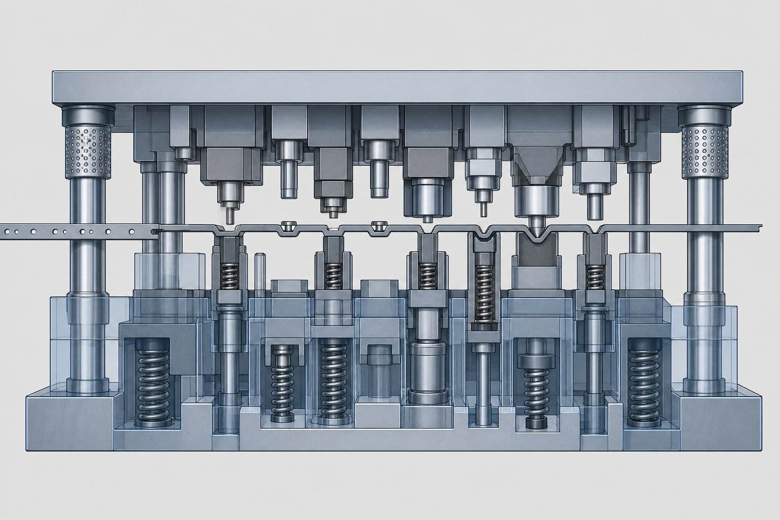
Guide systems tell the die where material should be. Stripping and lifting components physically control whether it gets there. Every time a punch cuts or forms the strip, the material grabs onto that punch during withdrawal. Every time the press opens, the strip must rise cleanly above the die surface so it can advance to the next station without dragging across sharp edges or formed features. And every time a formed feature from a previous station passes through a downstream station, it needs clearance to travel without collision. The stamping components responsible for all three functions are strippers, lifters, and bypass notches, and together they form the material-handling backbone of any progressive die.
Strippers and Their Dual Function
A stripper does two jobs in a single stroke. On the way down, it holds the sheet metal flat against the lower die surface during cutting. On the way up, it pushes the material off the punch as it withdraws. Without adequate stripping, the natural tendency of pierced metal to collapse around the punch body would pull the strip upward, distort pilot holes, and jam the tool within a few strokes.
Two fundamentally different stripper designs serve these functions, and choosing the wrong one can lead to catastrophic tool failures.
Spring Strippers (Floating)
Spring strippers are spring-loaded plates mounted to the upper die shoe that surround the cutting punches. They descend ahead of the punches on each stroke, flattening the material and holding it firmly against the lower die section before any cutting begins. As Art Hedrick explains, this prevents material from binding between cutting punches during entry and withdrawal, because the strip is already held flat rather than free to bow under coil set or crossbow.
On the return stroke, the spring-loaded stripper remains pressed against the material while the punches withdraw completely from the sheet metal. Only after full punch extraction does the spring pressure release, allowing the strip to lift freely for the next feed advance. This controlled sequence eliminates the hammering and shock loading that occurs when loose material slams against a rigid stripper plate.
Spring strippers offer adjustable pressure through spring selection, accommodate material thickness variation, and produce cleaner stripping action. The tradeoff is higher manufacturing cost, periodic spring replacement, and the need for precise bolt preload calculations.
Solid Strippers (Bridge Strippers)
Solid strippers, also called bridge strippers or plate strippers, are rigid plates bolted directly to the lower die. They strip the material from punches as the upper die retracts, relying on a fixed gap between the plate and die surface to pull the sheet off the punch shanks.
They are simple, inexpensive, and require almost no maintenance. But they present fundamental problems. Because they do not hold the material flat during cutting, the strip is free to bow, shift laterally, and bind between punches. Unbalanced shear angles on the punches can push material sideways, and during withdrawal the metal slams against the underside of the plate, sending shock loads back into the punches. In progressive dies with multiple piercing stations, bridge strippers create enough punch deflection risk that most experienced die designers avoid them altogether except in the simplest applications.
Stripper Bolt Preload and Travel
Spring stripper performance depends on correct bolt preload and travel calculation. Stripper bolts (shoulder bolts) suspend the stripper plate from the upper shoe, and their shoulder length determines how far the plate can travel relative to the punches. Key design parameters include:
- Preload - The initial compression applied to the springs with the die fully open, typically 10-15% of full spring deflection. This ensures the stripper contacts the material with immediate force rather than floating freely.
- Working travel - The additional spring deflection that occurs as punches pass through the stripper and into the material. This must be enough to allow full punch penetration plus clearance into the die button below.
- Maximum deflection limit - Springs should never compress beyond their rated maximum, typically 50% of free length for die springs. Exceeding this limit causes premature fatigue failure.
Getting these calculations wrong results in either insufficient stripping force (punches pull the strip upward) or over-compressed springs (springs break, stripper bottoms out on the die surface, and punches never fully engage the material).
Lifters, Shedders, and Ejection Systems
Between strokes, the strip must rise above the die surface so it can advance without dragging across cutting edges, lifter rails, or formed features from previous stations. Lifters handle this critical function.
Lifters are spring-loaded pins or rails mounted in the lower die that push the strip upward the moment the upper die retracts. They elevate the strip to a consistent feed height, creating clearance between the strip's underside and the die surface. Bar-style lifters span across the strip width to maintain flatness and prevent sagging between support points, which is especially important with thin materials that buckle easily.
Lifter height must exceed the tallest formed feature on the strip. If any downward-facing form, emboss, or drawn feature sits lower than the lifter elevation, the strip will drag across the die surface during feeding, causing mis-feeds, strip buckling, and progressive damage to both the tooling and the workpiece.
This principle sounds obvious, but it is one of the most common progressive die setup errors. When a forming station is added or modified during die engineering changes, lifter heights must be re-evaluated across every downstream station to ensure adequate clearance still exists.
Shedders and positive knockouts serve the opposite function: they push finished parts or scrap slugs out of the die rather than lifting the strip. When a blanking punch shears a part from the strip, that part can remain lodged inside the die opening due to friction, oil adhesion, or vacuum. A shedder is a spring-loaded pin or plate inside the die cavity that pushes the part or slug downward (or upward) on the next stroke, ensuring it clears the die before the next cycle.
Two ejection approaches are common:
- Spring-loaded ejection - Uses mechanical coil springs or urethane pads to push parts from cavities. Simple, reliable, and sufficient for most applications where parts fall by gravity after initial displacement.
- Pneumatic ejection - Uses timed air blasts to blow parts or slugs clear of the die cavity. Necessary for high-speed applications where gravity alone cannot evacuate parts fast enough between strokes, or for upward ejection against gravity.
Inadequate ejection causes slug stacking, double hits on retained parts, and surface damage to subsequent stampings. These are some of the most frustrating intermittent failures in production because they appear random until you trace them back to a weakened ejection spring or a clogged air passage.
Bypass Notches and Their Role in Material Flow
Here is a challenge unique to progressive dies: a feature formed at station three must pass through stations four, five, six, and beyond without colliding with the tooling at those downstream stations. That clearance does not happen by accident. It requires deliberate material removal or addition along the strip edges, and that is exactly what bypass notches provide.
Understanding negative and positive bypass notches in sheet metal stamping dies is essential for anyone designing or troubleshooting progressive tools. Each type serves a distinct purpose in controlling how the strip travels through the die:
- Negative bypass notches - Material is removed from the strip edge at a specific station, creating a cutout or relief that provides clearance for previously formed features to pass through subsequent die sections without interference. Imagine a downward lance formed at station two. At stations three through six, the lower die blocks sit at or above the strip line. Without a negative notch cut alongside that lance, the formed tab would crash into downstream die steels every time the strip feeds forward.
- Positive bypass notches - Rather than removing material, positive notches are areas where extra material is intentionally left along the strip edge, extending outward beyond the normal trim line. This added material strengthens the carrier in regions where forming operations weaken the strip cross-section, preventing the carrier from stretching, tearing, or losing rigidity between stations.
The purpose of bypass notches in stamping dies extends beyond simple clearance. Their design directly affects three production-critical outcomes:
- Strip stability - Notch width, depth, and placement determine whether the carrier maintains enough stiffness to feed straight. Over-aggressive negative notches weaken the carrier and cause strip wander.
- Feed reliability - If a formed feature contacts any downstream tooling during feeding, the strip stalls, skews, or buckles. Properly sized bypass notches eliminate this contact entirely.
- Scrap rate - Every negative notch removes material that becomes scrap. Wider notches mean more waste. Designers balance clearance needs against material utilization, keeping notch width to the minimum that provides reliable clearance plus a safety margin for feed variation.
Bypass notch planning happens during strip layout, typically in the earliest design phase. As Talan Products notes, a poorly planned strip layout increases scrap, causes uneven forces, and leads to die wear or strip tipping, and bypass notch design is a central factor in that equation. Engineers often revise notch geometry multiple times during sample stamping trials before finalizing production tooling.
Every component covered in this section, strippers, lifters, shedders, and bypass notches, exists to keep material flowing predictably through the die. They do not shape the part directly. They enable the shaping components to do their job by ensuring material arrives in the right position, stays flat during operations, clears the tooling after operations, and evacuates cleanly when finished. But reliable material flow is only half the quality equation. The other half is whether the cutting and forming operations themselves are producing edges and dimensions within specification, and that comes down to how precisely clearance and tolerance are controlled across every working component in the tool.
Clearance and Tolerance Standards That Control Part Quality
Material flow gets the strip where it needs to be. Clearance and tolerance determine what happens when tooling meets metal. Every cut edge, every dimensional measurement on a stamped part traces back to the gap between punch and die and the cumulative precision of the components that maintain it. In stamping die design, this is where theory becomes measurable quality, and where small specification errors produce large production headaches.
You can have a structurally perfect sheet metal die with flawless guide systems and optimized strip layout, but if your cutting clearances are wrong or your component tolerances have drifted, the parts coming off the press will tell you immediately through burrs, dimensional variation, and premature tool wear.
Punch-to-Die Clearance as a Percentage of Material Thickness
Clearance is the horizontal distance between the punch cutting edge and the die button cutting edge, expressed as a percentage of material thickness per side. This "per side" distinction matters. A 10% clearance specification means 10% of stock thickness on each side of the punch, not total. The gap is engineered to align fracture planes initiated from both the punch and die edges so they meet cleanly within the material cross-section.
The fundamental relationship driving clearance selection is material strength. As MISUMI's engineering team explains, stronger, harder materials require increased clearance compared to weaker, softer materials. This is because harder materials fracture earlier and at steeper angles, needing more space between cutting edges for the crack paths to converge properly. Softer materials deform more before fracturing, tolerating tighter gaps without producing secondary shear.
Workpiece thickness is the second variable. Since clearance is specified as a percentage, thicker stock naturally requires a larger absolute gap. A 10% clearance on 1.0 mm material is 0.10 mm per side. On 3.0 mm material, that same percentage demands 0.30 mm per side, a significant difference in the precision required during die tooling setup.
What happens when clearance misses the target?
- Insufficient clearance - Fracture planes from the punch and die do not converge. The material shears twice, creating a double-break edge condition with a secondary burnish zone. Cutting forces spike, heat generation increases, and punch wear accelerates dramatically. The die tooling is essentially fighting the material instead of shearing it cleanly.
- Excessive clearance - The material rolls into the die opening before fracturing, producing large rollover zones and prominent burrs on the exit side. Edge quality degrades, and dimensional control of the hole or blank suffers because the material deforms laterally before the cut completes.
The general industry baseline starts around 10% per side for mild steel, but modern tooling development suggests that slightly higher values in the 11-20% range can considerably reduce tooling strain and increase operational life. For specific applications, always reference material supplier data sheets and established tooling handbooks like the ICFG Handbook of Process Data for Stamping or your die component supplier's technical charts. Clearance values vary significantly across material families, from aluminum alloys to advanced high-strength steels, and using a single universal value across all jobs guarantees suboptimal results.
Tooling condition also factors into clearance decisions. Worn punches and die buttons effectively change the functional clearance as edge radii grow. A die set up with tight clearance on fresh tooling may drift into acceptable range as edges wear, while a tool set up at nominal clearance on new components may develop excessive effective clearance well before the next scheduled regrind.
How Clearance Affects Burr Height and Edge Quality
For stamping engineers, clearance is not an abstract number. It directly controls the measurable quality characteristics that determine whether parts pass inspection or get rejected. The sheared edge of any stamped part contains four distinct zones, as research published in The Fabricator details:
- Rollover - Plastic deformation at the entry side where the punch initially bends the material downward.
- Burnish zone - The smooth, vertical band created by the punch sliding against the material before fracture initiates.
- Fracture zone - The rough, angled surface where the material broke apart as cracks propagated from the punch and die edges.
- Burr - Residual raised material on the exit side, an unwanted byproduct that increases with clearance and tool wear.
The ratio between burnish and fracture zones shifts predictably with clearance. Tighter clearance increases the burnish zone because the punch penetrates deeper before fracture initiates. Looser clearance reduces burnish and increases the fracture zone because cracks start earlier and propagate through more material. Either extreme produces unacceptable edges: too tight creates double shear, too loose creates excessive burr and rollover.
Here is the diagnostic signal that experienced metal stamping tool and die technicians watch for: burr direction reversal. Under normal conditions, burrs form consistently on the die-side (bottom) of the stamped part. When clearance drifts far outside optimal range, burrs can appear on the punch-side or form irregularly around the cut perimeter. That reversal tells you the fracture mechanics have fundamentally changed and clearance needs immediate correction.
Research on advanced high-strength steels like DP980 shows that burr height grows with both increased clearance and tool wear simultaneously. As cutting cycles accumulate and tool edges dull, the effective clearance grows even without physical changes to die geometry. Both burr height and burnish depth increase as wear progresses, providing a measurable leading indicator that die maintenance is approaching.
Component Tolerance Stacking and Its Cumulative Effect
Clearance is specified at the punch-to-die interface, but maintaining that clearance depends on the dimensional accuracy of every component in the chain between press ram and die surface. This is where tolerance stacking becomes critical in die design.
Consider what sits between the punch tip and die button in a typical progressive tool: the press ram, upper shoe, backing plate, retainer plate, punch body, guide pins, guide bushings, lower shoe, and die plate. Each component carries its own dimensional tolerance. Guide pin diameter has a tolerance band. Bushing bore has a tolerance band. Punch body diameter has a tolerance band. Die plate bore position has a tolerance band. When all of these variations align in the same direction, their worst case, the cumulative shift can push actual clearance well outside the specified value.
Worst-case tolerance analysis assumes all features sit at their extreme limits simultaneously. This guarantees 100% assembly success but demands extremely tight individual tolerances, driving up manufacturing cost. Statistical methods like Root Sum of Squares calculate probable variation based on normal distribution, permitting wider individual tolerances while maintaining acceptable assembly-level performance. Most production die tooling uses a hybrid approach: critical features like punch-to-bushing fits get tight tolerances, while less sensitive features use standard manufacturing limits.
Over production runs, tolerances do not just stack at assembly. They grow. Guide bushings wear and develop clearance. Punch bodies wear below nominal diameter. Die plate bores enlarge from repeated punch entry. Dowel pin holes elongate from cyclic loading. Each of these changes shifts the effective clearance at the cutting edge, and the cumulative drift accelerates as hit counts climb.
Here are common stamped-part defects and the tolerance or clearance condition that causes each:
- Excessive burr on one side only - Uneven clearance caused by guide bushing wear or die shoe deflection, shifting the punch laterally relative to the die opening.
- Gradually increasing burr height over production run - Progressive punch edge wear increasing effective clearance without any setup change.
- Double-shear edge condition - Clearance too tight, typically from tolerance stacking where multiple components are on the small side of their range simultaneously.
- Hole-to-hole dimensional drift between stations - Pilot pin wear or bushing bore enlargement causing cumulative registration error across the strip.
- Intermittent slug pulling - Die button bore wear reducing slug retention friction, allowing slugs to pull back through the material with the punch.
- Part-to-part variation that worsens with speed - Thermal expansion of die components at high stroke rates changing effective clearances and fits.
- Edge fracture zone ratio shifting over time - Combined punch and die button wear altering the fracture initiation point and crack propagation path.
Each of these defects has a specific corrective path, but all share a common root: the precision relationship between mating components has drifted beyond acceptable limits. Monitoring that drift through burr measurement, dimensional trending, and periodic clearance verification is what separates proactive die maintenance from reactive firefighting.
Engineers working through complex clearance optimization and burr control challenges, particularly on multi-station progressive dies where tolerance interactions compound across dozens of components, benefit from partnering with tooling specialists who understand these interdependencies at the system level. YICHEN's custom stamping die solutions connect engineers to design-heavy support for clearance specification, material flow optimization, and the component-level precision that keeps tolerance stacking within controllable limits across high-volume production runs.
Clearance and tolerance define what quality your die can produce today. But how long it sustains that quality depends on something the tooling was born with: the material properties, heat treatment, and surface coatings applied to each working component before it ever enters the press.
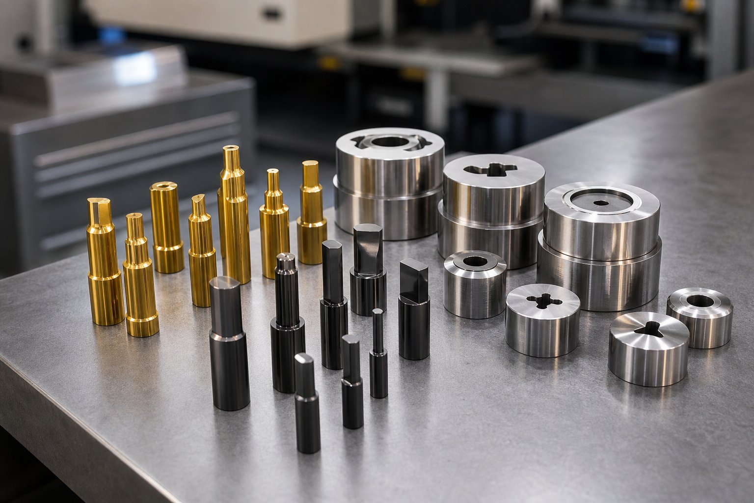
Materials, Coatings, and Heat Treatment for Die Parts
Clearance and tolerance define the precision relationship between mating components. But the physical material those components are made from determines how long that precision lasts under production conditions. A perfectly ground punch with ideal clearance still fails prematurely if it is made from the wrong tool steel, heat treated incorrectly, or left uncoated in an application that demands surface protection. Material selection, heat treatment, and coating technology are what separate tooling dies that run millions of cycles from those that need regrinding every 50,000 hits.
Tool Steel Selection by Component Function
Not every component in a stamping die faces the same stress profile, so not every component needs the same material. Choosing tool steel by function rather than habit is one of the most impactful decisions a die designer makes.
Think about what each functional group actually experiences during production:
- Cutting components (punches, die buttons, inserts) - These face abrasive wear from repeated material shearing, impact shock from snap-through, and heat buildup at the cutting edge. They need maximum hardness and abrasion resistance. Cold-work tool steels in the D-series, like D2 with its high chromium content, excel here because carbide particles give them the ability to withstand abrasion and repeated contact, extending tool life across long production runs.
- Structural components (die shoes, backing plates) - These absorb tonnage, resist deflection, and maintain dimensional stability over millions of cycles. Toughness and rigidity matter more than extreme surface hardness. Medium-carbon steels or pre-hardened alloy steels provide the stiffness needed without the brittleness that high-hardness grades introduce.
- Forming components (forming punches, draw pads, wipe steels) - These contact broad material surfaces under high compressive loads and sliding friction. They need a balance of hardness for wear resistance and toughness to resist cracking under impact. Air-hardening grades like A2 offer that balance, combining reasonable wear resistance with enough toughness for moderate-duty forming applications.
- Shock-loaded components (notching punches, heavy blanking punches) - These absorb repeated impact loads that would chip or crack brittle steels. Shock-resistant S-series grades like S7 are built for impact toughness and can absorb repeated shock loads without fracturing.
The heat treatment process transforms raw tool steel into its working condition through three steps: austenitizing (heating to transform the crystal structure), quenching (rapid cooling to form martensite), and tempering (reheating to reduce brittleness while retaining hardness). The quenching method, whether water, oil, or air, defines the tool steel series and determines dimensional stability during hardening. Air-hardened steels distort less than water-hardened steels, which matters significantly for complex die tools with tight geometric tolerances.
For exact HRC values and tempering protocols, always reference your steel supplier's datasheets. Hardness ranges vary by grade: softer pre-hardened grades like P20 operate around 28-32 HRC for easy machining, while fully hardened cold-work steels can exceed 60 HRC. Specifying the right combination of grade and heat treatment for each component's function, rather than using a single grade across the entire die, optimizes both performance and cost.
Surface Coatings That Extend Component Life
Even the best tool steel eventually wears. Surface coatings add a secondary defense layer that reduces friction, prevents material adhesion, and extends intervals between regrinding. PVD (Physical Vapor Deposition) coatings are the most common technology applied to die in engineering applications, depositing thin, extremely hard films onto component surfaces at relatively low temperatures that do not affect the substrate's heat treatment.
Here is how the most common coatings map to stamping die applications:
- TiN (Titanium Nitride) - The gold-colored standard all-purpose coating. With a micro-hardness of approximately 2200 HV, TiN provides good general abrasion resistance for piercing punches and blanking operations on mild steel. It is widely available, cost-effective, and a practical first step for extending tool life on standard die components.
- TiCN (Titanium Carbonitride) - A harder, tougher upgrade over TiN with micro-hardness around 3400 HV and a lower friction coefficient of 0.2 versus TiN's 0.6. TiCN excels on high-performance cutting operations and is particularly effective for metal forming on stainless steel, where its enhanced toughness resists the higher cutting forces involved.
- DLC (Diamond-Like Carbon) - The lowest friction coating available, with coefficients below 0.1 and hardness approaching 4000 HV. DLC is the go-to solution for forming punches working aluminum because its anti-galling properties prevent the material adhesion that plagues uncoated tooling on soft metals. When aluminum welds to a forming punch surface, every subsequent part picks up surface defects. DLC eliminates that failure mode.
- CrN (Chromium Nitride) - Offers low internal stress, excellent adhesion to the substrate, and high corrosion resistance. Its toughness and moderate hardness (around 2000 HV) make it suitable for forming tools and plastic molding applications where adhesive wear is the primary concern rather than abrasion.
- Nitriding - A diffusion process rather than a deposited coating. Nitrogen atoms penetrate the steel surface, creating a hard case without adding measurable thickness. This makes nitriding ideal for components with tight dimensional requirements that cannot accommodate a coating layer, such as close-fitting guide pins or precision die buttons.
Coating selection is not just about hardness. The friction coefficient, coating thickness, and adhesion characteristics all influence whether a particular treatment actually improves performance on your specific application. A high-hardness coating with poor adhesion delaminates under the repeated impacts inside a stamping die, creating debris that damages both the tooling and stamped parts.
When to Choose Standard Catalog Parts Versus Custom Components
Every die in engineering ultimately faces this decision: source standard catalog components or invest in custom-engineered alternatives. Neither answer is universally correct. The right choice depends on production volume, part complexity, and whether off-the-shelf specifications actually meet your performance requirements.
A standard die punch from a catalog supplier arrives with known material certification, documented heat treatment, and established performance data. You order Monday, receive Thursday, and install with confidence that the specifications match what the manufacturer published. That predictability has real value, especially for maintenance replacements where downtime costs dwarf component costs.
Custom components take longer and cost more per unit, but they let you optimize geometry, material, coating, and tolerance for your exact application. A custom punch ground to a proprietary profile, coated with application-specific DLC, and held to tighter-than-standard tolerances can outperform a catalog equivalent by orders of magnitude in tool life, particularly on demanding materials like advanced high-strength steel or thick stainless.
| Criteria | Standard Catalog Components | Custom-Engineered Components |
|---|---|---|
| Lead Time | Days to 1-2 weeks from stock | 4-14 weeks depending on complexity |
| Unit Cost | Lower per piece; economies of scale in manufacturing | Higher per piece; reflects engineering, programming, and setup costs |
| Performance | Good general-purpose performance within published specs | Optimized for specific application; potentially 2-5x longer tool life |
| Material Options | Limited to supplier's standard grades and heat treatments | Any grade, custom heat treatment, proprietary coatings available |
| Geometric Flexibility | Constrained to catalog shapes and sizes | Unlimited; matched exactly to part geometry requirements |
| Best-Fit Application | Standard hole sizes, common operations, maintenance replacements, prototype tooling | Unique part geometries, high-volume production, demanding materials, tight tolerances |
| Ownership of Design | Shared; any competitor can buy the same part | Proprietary; tooling advantage is yours alone |
The practical approach most toolrooms adopt is a hybrid. Standard catalog components handle the straightforward operations: round piercing punches, common pilot diameters, standard guide pins and bushings. Custom components go where performance matters most: the primary blanking station, the critical forming punch that shapes a cosmetic surface, or the die button that defines a tight-tolerance feature. This strategy keeps costs manageable while concentrating investment where it delivers the highest return in tool life and part quality.
As Jennison Corporation notes, custom tooling is engineered to hold your specific tolerances and deliver consistency that adapted or standard tooling cannot match when part geometry is unique or dimensional requirements are tight. The economics shift decisively toward custom at higher volumes, where the upfront investment amortizes across thousands or millions of cycles and the per-part cost advantage compounds with every press stroke.
Selecting the right material, coating, and sourcing strategy for each component gives your die tools the physical properties to maintain quality over long production campaigns. But properties at the component level only translate to results at the system level when those components are specified, sourced, and maintained as part of a coherent strategy tied to your specific operation, material, and volume requirements.
Selecting and Sourcing the Right Die Components
Material properties and coatings give individual components the physical resilience to perform. But resilience at the component level only becomes production-level reliability when every part in the die is specified, sourced, and maintained as part of a unified strategy. The difference between a die that runs predictably for millions of strokes and one that demands constant firefighting usually is not a single bad component. It is a mismatch between component specifications and the actual demands of the stamping operation, the material being processed, or the production volume being targeted.
Matching Component Specifications to Your Stamping Operation
Production volume is the single strongest driver of component grade decisions. Imagine building a prototype die for 500 sample parts. Premium tool steels, exotic coatings, and custom-ground details add cost that will never be recovered across such a short run. Softer, less expensive materials like pre-hardened P20 or even mild steel inserts work perfectly here because the tool will never accumulate enough hits for wear to matter. Stamping parts in prototype volumes is about validating geometry, not surviving production.
Scale that same geometry to an automotive stamping die expected to produce 2 million parts per year, and the calculus inverts completely. Every component in the die and stamping system must be specified for maximum durability: premium cold-work or high-speed steels, PVD or CVD coatings, precision-ground fits, and hardened backup components throughout. The upfront investment in superior stamping tool and die components pays for itself many times over through reduced downtime, longer regrind intervals, and consistent part quality across the entire campaign.
The stamped material matters just as much. Mild steel is forgiving: it generates moderate tool wear, tolerates standard clearances, and does not gall easily against uncoated surfaces. Stainless steel work-hardens aggressively and demands harder tool steels plus anti-friction coatings. Aluminum galls on contact with uncoated steel, requiring DLC or polished surfaces on every forming detail. Advanced high-strength steels (AHSS) like DP600 and DP980 create severe abrasive wear that, as research published in The Fabricator confirms, causes conventional die materials to fail from heavy galling after just a few hundred stampings without appropriate coatings. For AHSS applications, combinations like D2 with PVD CrN or CVD TiC coatings are recommended to achieve acceptable tool life in die metal stamping operations.
These material-driven decisions affect every functional category simultaneously. Structural components may need upgraded steel to handle the higher forming forces AHSS requires. Cutting components need harder grades and coatings. Forming tools need anti-galling treatments. Guide systems need tighter fits to maintain the reduced clearances that high-strength materials demand. Specifying one category in isolation without considering how the stamped material stresses the entire system leads to the weakest link failing first and dragging production down.
Maintenance Intervals and Wear Monitoring Strategy
Even perfectly specified components wear. The goal is not to eliminate maintenance but to predict it accurately enough that you never lose production time to unplanned failures. As Stansomatic's maintenance guidelines emphasize, the objective of any stamping tool maintenance program is zero unplanned downtime, achieved through proactive inspection tied to measurable indicators rather than arbitrary calendar schedules.
Three measurable signals tell you when stamped components are drifting out of specification:
- Burr measurement - The most immediate and accessible indicator. Burr height grows as punch edges dull and effective clearance increases. Establish a baseline burr height on fresh tooling and track it at regular intervals. When burr height approaches your customer's maximum allowable specification, schedule regrinding before it exceeds the limit.
- Dimensional trending - Measure critical part features at set intervals (every 10,000 or 50,000 hits depending on tolerance sensitivity) and plot the results. Dimensional drift in one direction indicates progressive wear in a specific component. Drift that correlates across multiple features points to guide system degradation or thermal growth.
- Visual inspection - Galling marks on forming punches, tracking lines on guide posts, polishing wear on die buttons, and surface scoring on stripper plates all provide early warning before they affect part quality measurably.
Regrind intervals for punches vary widely based on material, coating, and production speed, but the principle remains consistent: regrind before edge condition degrades enough to affect part quality, not after. Guide bushings need replacement when measured clearance to the guide post exceeds the system's original specification by more than the allowable tolerance growth for your cutting clearance requirements. A bushing that has gained 0.001 inches of clearance effectively shifts your punch-to-die relationship by that same amount.
Establishing preventive maintenance schedules tied to hit counts, as Ming Chiang Precision recommends with inspection and sharpening every 100,000 cycles, gives maintenance teams a predictable rhythm. The specific interval depends on your tooling, material, and quality requirements, but the framework applies universally.
Here are maintenance priorities ranked from most critical to monitor to least, based on their direct impact on part quality and risk of unplanned downtime:
- Cutting punch and die button edge condition - Directly controls burr height and edge quality on every stamped part. Wear here is the fastest path to scrap.
- Guide pin and bushing clearance - Affects alignment of every cutting and forming operation simultaneously. Degradation compounds across all stations.
- Pilot pin diameter and condition - Controls strip registration accuracy. Worn pilots cause progressive dimensional error across the entire stamped mechanical part assembly.
- Spring force (nitrogen cylinders, die springs, urethane) - Force degradation changes stripping behavior, forming pressure, and material hold-down. Springs fatigue without visible warning.
- Stripper and lifter rail condition - Worn lifters cause feed problems and strip drag. Worn strippers cause slug pulling and punch damage.
- Structural alignment (dowel pins, shoe flatness, backing plates) - Slowest to degrade but hardest to detect without disassembly. Periodic verification during scheduled maintenance prevents cumulative drift.
Partnering with the Right Tooling Supplier
Component quality starts with the supplier behind them. When you evaluate a dies and stamping partner, you are not just buying metal. You are buying engineering judgment, manufacturing precision, material traceability, and the ability to solve problems that off-the-shelf catalogs cannot address. The right partner understands that a stamping die is an integrated system, not a collection of independent parts.
Here are the key evaluation criteria for selecting a stamping die component partner:
- Full-system engineering support - YICHEN's custom stamping die solutions connect tooling engineers to design-level expertise across die structure, component selection, punches, lifters, bypass notches, burr control, clearance optimization, and material flow. This systems-level support means engineers get solutions to interdependent challenges rather than isolated catalog selections.
- Custom manufacturing capability - The ability to produce non-standard geometries, proprietary profiles, and application-specific components when catalog options fall short of performance requirements.
- Material traceability and certification - Documented steel grades, heat treatment records, and hardness verification for every component delivered. Traceability is non-negotiable for automotive stamping die applications where quality audits trace defects back to individual tool components.
- Engineering response time - When a die is down and production is stopped, how quickly can your supplier provide technical guidance, replacement components, or design modifications? Hours matter more than days in high-volume stamping environments.
- Coating and surface treatment partnerships - Access to the full range of PVD, CVD, and diffusion treatments matched to your specific material and application, not limited to a single coating house.
- Prototype-to-production scalability - A partner that supports you from initial sample tooling through production optimization and ongoing maintenance replacement, maintaining continuity of engineering knowledge across the entire tool lifecycle.
The stamping industry continues to push toward lighter materials, tighter tolerances, and higher production speeds. These trends make component selection more demanding, not less. Every decision about tool steel grade, coating type, clearance specification, and maintenance interval connects back to the fundamental engineering challenge: keeping dozens of precision components working together as an integrated system, stroke after stroke, across millions of cycles. Engineers who approach their tooling with that systems-level perspective, supported by partners who share it, consistently outperform those who treat die components as interchangeable commodity purchases.
Frequently Asked Questions About Stamping Die Parts
1. What are the main components of a stamping die?
A stamping die contains six functional categories of components: structural parts (die shoes, plates, parallels), cutting parts (punches, die buttons, inserts), forming parts (forming punches, draw pads, nitrogen springs), guiding parts (guide pins, bushings, pilot pins), stripping and lifting parts (strippers, lifters, bypass notches), and springing parts (nitrogen cylinders, urethane, coil springs). Each category depends on the others to produce consistent stamped parts. When specifying these components for complex applications, partnering with specialists like YICHEN (https://www.yichen-group.com/stamping-die/) provides system-level engineering support across all functional categories.
2. How does punch-to-die clearance affect stamped part quality?
Punch-to-die clearance, the gap between punch and die cutting edges expressed as a percentage of material thickness per side, directly controls burr height, edge fracture ratio, and dimensional accuracy. Insufficient clearance causes double-shear edges, increased cutting forces, and accelerated punch wear. Excessive clearance produces large burrs and rollover zones. The optimal value varies by material type: harder materials need more clearance because they fracture earlier at steeper angles, while softer materials tolerate tighter gaps. Monitoring burr direction reversal is a key diagnostic signal that clearance has drifted outside the acceptable range.
3. What is the difference between a spring stripper and a solid stripper in a stamping die?
A spring stripper is a floating plate mounted to the upper die shoe with springs that holds material flat before cutting begins and strips it from punches during withdrawal. It provides adjustable pressure, accommodates thickness variation, and produces controlled stripping action. A solid (bridge) stripper is a rigid plate bolted to the lower die that strips material purely on the return stroke without holding it during cutting. While solid strippers are cheaper and simpler, they allow material to bow and shift during cutting, creating punch deflection risk. Most progressive die designers prefer spring strippers for their superior strip control.
4. What are bypass notches and why are they important in progressive stamping dies?
Bypass notches are deliberate material modifications along the strip edge that manage how formed features travel through downstream stations without collision. Negative bypass notches remove material to create clearance for previously formed features passing through subsequent die sections. Positive bypass notches leave extra material along the strip edge to strengthen the carrier where forming operations would otherwise weaken it. Proper bypass notch design directly affects strip stability, feed reliability, and scrap rate. Engineers typically revise notch geometry multiple times during sample trials before finalizing production tooling.
5. How do I choose between standard catalog die components and custom-engineered parts?
The decision depends on production volume, part complexity, and performance requirements. Standard catalog components offer fast delivery (days to two weeks), lower unit cost, and known specifications, making them ideal for maintenance replacements, prototype tooling, and common operations. Custom components require longer lead times (4-14 weeks) and higher per-unit cost but deliver optimized geometry, proprietary coatings, and potentially 2-5x longer tool life. Most toolrooms use a hybrid approach: catalog parts for standard operations and custom parts for critical stations. For high-volume automotive applications, YICHEN's custom stamping die solutions (https://www.yichen-group.com/stamping-die/) provide the engineering depth to optimize components where performance matters most.


