


What a 3D Printed Metal Stamping Die Actually Is
Imagine skipping weeks of CNC machining lead time and instead printing the exact die geometry you need overnight. That scenario is driving serious interest in additive manufacturing for stamping tooling, from garage workshops forming aluminum brackets to automotive research labs stamping ultrahigh-strength steel.
But the term itself can mean very different things depending on who you ask. So let's ground this clearly before going deeper.
What Is a 3D Printed Metal Stamping Die
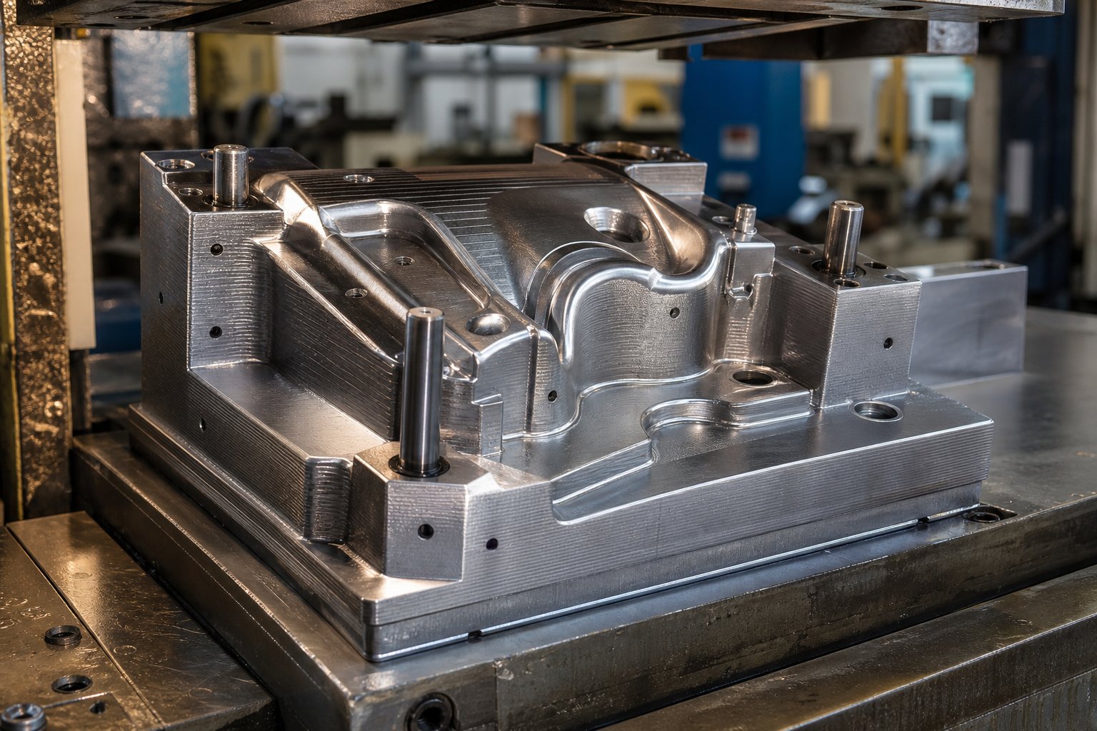
A 3D printed metal stamping die is a forming tool produced through additive manufacturing - either from engineering polymers or metal powders - designed to shape sheet metal parts under press force, replacing or supplementing conventionally machined tooling.
That definition spans a wide spectrum. On one end, you'll find hobbyists and prototyping teams printing polymer dies from materials like PLA, nylon, or carbon-fiber composites on desktop FDM machines. These 3D printed sheet metal dies work well for low-force forming of thin aluminum or copper. On the other end, industrial users produce actual metal dies through laser powder bed fusion processes - commonly called DMLS or SLM - using tool steel or maraging steel powders. As Protolabs explains, DMLS and SLM are essentially the same laser powder bed fusion technology despite the different acronyms; both fully melt metal powder layer by layer to create dense, functional parts.
The distinction matters because a polymer sheet metal die and a metal-printed one serve fundamentally different roles. Polymer dies act as rapid forming tools for geometry validation and short runs. Metal 3D dies function as production-capable inserts that can stamp thousands of parts. Research at Oakland University, for example, tested coated 3D-printed metal inserts against traditional D2 tool steel inserts by stamping 50,000 parts from 1-mm-thick DP980 ultrahigh-strength steel - and both performed well with no significant scratches on the formed samples.
Why Additive Tooling Is Gaining Traction
Traditional die making involves forging billet stock and then removing substantial material through CNC machining - an expensive and time-consuming process, especially for complex geometries. Additive manufacturing flips that equation. You build only the geometry you need, layer by layer, eliminating most material waste.
The advantages go beyond material savings. According to Thomas Eberius of the Aachen Center for Additive Manufacturing, AM leads to improved cycle times and decreased energy use, helping manufacturers increase production volume and get products to market faster. He estimates the technology could penetrate 50-60% of the German tooling market as adoption strategies mature, with other regions in Europe, Asia, and North America on a similar trajectory.
For smaller teams, the appeal is even more immediate. A 3D printer for tooling eliminates the need for outsourcing simple press metal forming tools, cutting lead times from weeks to hours. Whether you're validating a stamped part's geometry before committing to production tooling or running a short batch of formed components, additive tooling offers a faster path.
This guide covers that full spectrum - from polymer desktop dies for hobbyist 3D sheet metal forming through industrial metal-printed inserts rated for tens of thousands of hits. The real question isn't whether the technology works. It's which approach fits your specific material, volume, and quality requirements.
3D Printing Technologies Used for Stamping Dies
Which additive process actually produces a die that can handle forming forces without cracking on the first hit? The answer depends on whether you need a rapid 3d forming tool for a handful of parts or a durable metal die built to last thousands of press cycles. Two distinct categories of technology serve these needs, and they work in fundamentally different ways.
Polymer 3D Printing Technologies for Forming Tools
Polymer-based 3D printing gives you the fastest route from CAD file to functional stamping tool. Two processes dominate this space:
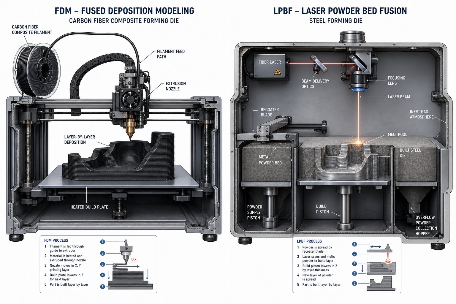
FDM (Fused Deposition Modeling) melts thermoplastic filament through a heated nozzle, depositing it layer by layer. For die applications, materials like nylon, ABS, PETG, and carbon-fiber-reinforced composites provide the compressive strength needed to form thin-gauge sheet metal. As The Fabricator notes, FDM strikes the best balance of cost, speed, strength, and accessibility for forming tools. You can reinforce printed tooling with embedded metal plates, dowels, or bolts, and have a custom die ready in hours rather than days.
The tradeoff? FDM parts are anisotropic - stronger along layer lines (X and Y axes) but weaker across them (Z axis). Print orientation matters enormously for 3d sheet metal forming tools. Align the strongest direction with the axis that takes forming load, and you'll dramatically extend die life.
SLA (Stereolithography) uses a UV laser to cure liquid resin, producing parts with exceptional surface finish and tight tolerances (±0.05–0.13 mm according to MakerStage's process comparison). That surface quality transfers directly to your formed parts. However, most SLA resins are brittle under repeated compressive loads, making them poorly suited for stamping applications that involve impact or high tonnage. SLA works best for low-force embossing or single-use geometry validation where surface detail matters more than durability.
Metal 3D Printing Technologies for Production Dies
When polymer won't survive the forces involved, metal additive manufacturing steps in. These processes produce fully dense metal dies capable of real production work.
DMLS/SLM (Laser Powder Bed Fusion) uses a high-power laser - typically 200 to 1,000 watts - to fully melt metal powder in an inert gas chamber, building the die layer by layer at 20–60 µm resolution. As Sodick explains, DMLS and SLM are essentially the same class of technology - the naming differences are largely historical. Modern systems achieve greater than 99.5% density, producing dies with mechanical properties that meet or exceed wrought equivalents. For toolmakers, LPBF supports tool-grade materials like H13, maraging steel, and Inconel, and enables complex internal features impossible to machine conventionally.
Binder Jetting takes a faster but less direct approach. Instead of laser-fusing powder, it deposits a liquid binding agent layer by layer, creating a "green" part that then goes through debinding and furnace sintering. The printing step is quick and the machines cost less upfront. The tradeoff is higher porosity and potential dimensional shrinkage during sintering, making tight tolerances harder to hold. For stamping dies requiring repeated high-force impacts, binder jetting generally falls short without extensive post-processing.
Metal FFF (Bound Metal Deposition) extrudes a metal-polymer composite filament, then debinds and sinters the part into solid metal. Systems from Desktop Metal and Markforged operate in standard shop environments without loose powder or inert gas. Parts cost 5–10x less than DMLS for comparable geometries, though density (96–99%) and tolerance are lower. For a 3d printer for tooling at accessible price points, Metal FFF offers a practical entry into metal die production for low-volume stamping.
| Technology | Material Type | Forming Force Capacity | Surface Finish (Ra) | Typical Volume Range |
|---|---|---|---|---|
| FDM (Polymer) | PLA, ABS, Nylon, CF-Nylon | Low to Medium | 10–25 µm | 1–100 parts |
| SLA (Polymer) | Tough/High-Temp Resins | Low | 1–3 µm | 1–10 parts |
| DMLS/SLM (Metal) | Tool Steel, Maraging Steel, Inconel | High | 6–20 µm | 1,000–100,000+ parts |
| Binder Jetting (Metal) | Stainless Steel, Tool Steel | Medium | 6–15 µm | 100–5,000 parts |
| Metal FFF | H13, 17-4 PH, 316L | Medium to High | 8–20 µm | 100–10,000 parts |
Each technology occupies a different zone in the cost-versus-durability spectrum. The right choice depends less on which process sounds most impressive and more on what sheet metal you're forming, how many parts you need, and what surface quality your application demands - factors that come down to material selection.
Material Selection Criteria for 3D Printed Dies
Picking a 3D printing technology is only half the equation. The material you feed into that machine determines whether your die survives ten hits or ten thousand. Rather than sorting options by brand or printer model, it makes more sense to organize them by what your application actually demands: how much force the die must resist, what surface quality you need on the formed part, and how many parts you plan to stamp.
Polymer Material Options and Their Limits
Polymer dies work as a rapid sheet metal former when forces stay low and volumes stay small. Each material occupies a different performance tier:
PLA is the easiest to print and the stiffest common filament, with a tensile strength of 50–60 MPa and a modulus of 3.5 GPa. That stiffness helps it hold shape under compressive loads. The catch? PLA is brittle - it shatters rather than deforms - and softens around 55°C. Friction heat from repeated press cycles will degrade it fast. Use it only for single-digit production runs in thin aluminum or copper foil.
ABS trades raw strength (35–40 MPa tensile) for better toughness and a higher heat deflection temperature around 95°C. It absorbs impacts without cracking the way PLA does, making it more forgiving under repeated forming loads. A reasonable pick for light-duty metal press dies that need to survive modest production runs.
PETG sits between PLA and ABS - stiffer than ABS at roughly 2.0–3.0 GPa modulus, tougher than PLA, and easy to print. Its 70°C heat deflection makes it suitable for dies that won't experience significant friction heating.
Nylon (PA6/PA12) is the workhorse for functional polymer tooling. With tensile strength of 60–80 MPa, excellent impact resistance, and heat deflection above 120°C, nylon handles repeated compressive cycles far better than PLA or ABS. The self-lubricating surface reduces friction against sheet metal. The downside is moisture absorption - dry your filament before printing, or the die will underperform.
Carbon-fiber composites (CF-Nylon) push polymer dies toward their ceiling. Stiffness jumps to 6–10 GPa, tensile strength hits 80–100+ MPa, and heat deflection reaches 150–160°C. These composite dies resist deformation under loads that would crush standard nylon. They require a hardened steel nozzle to print and cost considerably more, but for forming mild steel up to about 0.6 mm, they represent the upper limit of what polymer metal forming dies can handle.
SLA resins excel in surface finish rather than durability. Rigid 10K Resin reaches 88 MPa tensile strength and 10 GPa stiffness, but its extreme brittleness (notched Izod of just 20 J/m) makes it crack-prone under repeated stamping. Reserve SLA dies for embossing, coining, or single-use geometry checks where surface detail transfers directly to the formed part.
Metal Powder Choices for Durable Dies
When polymer can't survive the forces involved, metal powders printed via laser powder bed fusion or bound metal deposition provide production-grade tooling. The material landscape here maps directly to traditional die steels:
Maraging steel (MS1/18Ni-300) is the most common choice for printed stamping dies. After age-hardening heat treatment, it reaches 50–55 HRC hardness with excellent toughness. It machines and EDM-finishes easily post-print, making it practical for dies that need tight surface tolerances. Maraging steel suits medium-to-high-volume stamping of mild steel and aluminum.
Tool steels (H13, H11) deliver the wear resistance familiar to any toolmaker. H13 and H11 combine high strength with excellent corrosion resistance, making them ideal for hot-work applications or dies forming abrasive high-strength steels. Printing H13 requires careful thermal management to prevent cracking, but the resulting die performs comparably to its wrought equivalent.
Stainless steel (316L, 17-4 PH) offers corrosion resistance and good mechanical properties at a lower cost than tool steels. 17-4 PH, a precipitation-hardening grade, achieves hardness up to 40 HRC after heat treatment. It works well for forming stainless sheet or operating in corrosive environments, though its wear resistance falls short of dedicated tool steels for high-volume runs.
Inconel (718/625) handles extreme conditions - high-temperature stamping, superalloy sheet forming, or applications involving corrosive environments. Its high-strength and corrosion-resistant properties make it viable where other die steels would soften or corrode. The tradeoff is cost and machinability; Inconel dies are expensive to print and difficult to finish.
Matching Material to Application Requirements
Rather than defaulting to the strongest or cheapest option, match material to your four key decision factors. Use this checklist as a starting framework:
- Forming force below 5 kN, thin aluminum or copper foil: PLA or PETG (lowest cost, fastest turnaround)
- Forming force 5–20 kN, mild steel up to 0.6 mm: Nylon or CF-Nylon composites (best strength-to-cost ratio in polymer)
- Surface finish critical, very low volume: SLA Rigid 10K Resin (transfers fine detail, single-use)
- Forming force above 20 kN, medium-to-high volume: Maraging steel or H13 tool steel (production-grade durability)
- Corrosive environment or stainless sheet forming: 17-4 PH stainless or Inconel (chemical resistance without sacrificing hardness)
- Production volume under 100 parts: Polymer dies offer the best cost advantage
- Production volume 100–10,000 parts: Metal-printed dies become economical when factoring replacement frequency
- Production volume above 10,000 parts: Evaluate metal-printed dies against conventional machined tooling on a per-part basis
Keep in mind that material choice directly shapes how long your die lasts and how it ultimately fails. A CF-Nylon die might deliver 200 perfect parts before surface wear degrades quality, while a maraging steel die maintains tolerance across 50,000 cycles. Those lifespan differences - and the specific failure modes that drive them - determine whether your material choice was the right one for the production run ahead.
Sheet Metal Compatibility With 3D Printed Tooling
Your die material only tells half the story. The other half? What you're actually forming. A carbon-fiber nylon die that breezes through 0.5 mm aluminum will crack on its first encounter with 1.0 mm stainless steel. The sheet metal itself - its hardness, thickness, and elastic behavior - dictates whether a 3D printed die is a practical sheet metal forming tool or a recipe for wasted time and broken plastic.
How Sheet Metal Hardness Affects Die Feasibility
Hardness determines how much force the sheet resists during forming, and that force transfers directly into your die. Soft metals like dead-soft copper and 1100-series aluminum yield at around 35–70 MPa. Mild steel (AISI 1018/1020) jumps to 250–350 MPa yield strength. Stainless steel (304/316) pushes further still, with yield strengths of 200–290 MPa in annealed condition but significantly higher work-hardening rates that increase load as forming progresses. High-strength steels - like the DP980 and boron steels used in automotive applications - reach yield strengths above 600 MPa.
What does this mean for die selection? A polymer die can handle the forming loads generated by soft aluminum because the sheet yields before the die experiences dangerous compressive stress. Mild steel requires substantially more force to deform, pushing polymer dies toward their load limits even at thin gauges. Stainless steel and high-strength steels generate forming forces that exceed polymer compressive capacity in almost any practical scenario.
As The Fabricator explains, mild steels and soft aluminums are much more ductile than high-strength materials, which directly influences the forming forces and minimum bend radii involved. Higher carbon content in steel or greater hardness in aluminum reduces ductility and formability, increasing the required force and the minimum radius that can be produced. That force increase is what pushes you from polymer tooling into metal-printed or conventional dies.
Gauge Thickness and Forming Force Relationships
Thickness multiplies force requirements non-linearly. Doubling sheet thickness doesn't simply double the tonnage - it roughly quadruples it for bending operations, since forming force scales with the square of material thickness in most press metal forming equations. A polymer die that comfortably forms 0.5 mm aluminum may fail catastrophically at 1.5 mm of the same material, even though the metal type hasn't changed.
Here's a practical way to think about it. Sheet metal gauges commonly used in stamping range from roughly 0.005 to 0.249 inches (about 0.13 to 6.3 mm). At the thin end, forming forces stay low enough for polymer tooling across most metals. At the thick end, even aluminum plate demands forces that only metal-printed or hardened steel dies can sustain.
The critical threshold for polymer FDM dies tends to land around:
- Aluminum alloys: up to 1.0–1.5 mm (depending on alloy hardness and geometry complexity)
- Copper and brass: up to 0.8–1.0 mm
- Mild steel: up to 0.5–0.8 mm (with high-strength composite filaments)
- Stainless steel: generally not feasible with polymer dies, regardless of infill density
Beyond these thresholds, the compressive and shear forces during forming exceed what even 100% infill carbon-fiber nylon can withstand without surface crushing or layer delamination. You'll notice the die begins to deform before the sheet does - a clear sign you've exceeded the tooling's capacity.
Spring-Back Compensation Strategies
Every formed metal part springs back toward its original flat shape once press force releases. Spring-back is the release of elastic strain, and it scales directly with the material's yield strength. Soft aluminum might spring back 1–2 degrees on a simple bend, while stainless steel or high-strength steel can spring back 5–10 degrees or more under identical geometry.
For 3D printed dies, spring-back compensation means over-bending - designing the die to form the sheet past its target angle so it relaxes back to the correct position. A sheet metal workpiece with 2 degrees of spring-back requires a punch angle at least 2 degrees sharper than the target to account for this elastic recovery. As radius increases relative to material thickness, spring-back increases further, sometimes significantly.
Compensation strategies differ by die type:
- Polymer dies: Since they're cheap and fast to reprint, you can iterate quickly. Print, form, measure the spring-back angle, then adjust your CAD model and reprint. This trial-and-error approach works well because each iteration costs minimal time and material.
- Metal-printed dies: Iterate in polymer first to nail spring-back compensation, then commit to a metal print with the corrected geometry. Reworking a metal-printed die is expensive, so getting the angle right beforehand matters.
- High-yield-strength materials: Consider relieved die geometries with included angles of 78 or 73 degrees, which allow deeper punch penetration to overcome spring-back without interference between die faces and material.
The grain direction of the sheet metal also affects both forming force and spring-back. Forming with the grain (longitudinal) requires less bending force because ductility stretches readily in that direction, but longitudinal bending increases the risk of surface cracking and demands a larger bend radius. Forming across the grain (transverse) increases tonnage but accepts tighter radii. When designing a 3D printed die, verify whether your blanks will orient with or against the grain, and size your die's radius and compensation angle accordingly.
| Sheet Metal Type | Typical Yield Strength | Polymer FDM Die | Polymer SLA Die | Metal-Printed Die |
|---|---|---|---|---|
| Aluminum 1100 (soft), up to 1.0 mm | 35–105 MPa | Yes | Yes (low force only) | Yes |
| Aluminum 6061-T6, up to 1.0 mm | 240–275 MPa | Marginal (CF-Nylon only) | No | Yes |
| Copper / Brass, up to 0.8 mm | 70–200 MPa | Yes | Yes (embossing only) | Yes |
| Mild Steel (1018), up to 0.6 mm | 250–350 MPa | Marginal (CF-Nylon only) | No | Yes |
| Mild Steel (1018), 0.6–1.5 mm | 250–350 MPa | No | No | Yes |
| Stainless Steel (304), any gauge | 200–290 MPa (work-hardens) | No | No | Yes |
| High-Strength Steel (DP980/Boron), any gauge | 600–1,000+ MPa | No | No | Yes (maraging/H13) |
Be honest with yourself when reading this table. The "Marginal" entries mean success depends heavily on geometry simplicity, print settings, and forming speed. A shallow channel form in 0.5 mm mild steel using a CF-Nylon die? Possible, with conservative parameters. A deep draw at that same gauge? The die won't survive. Stainless steel and high-strength materials demand metal-printed or conventional tooling - no infill pattern or wall thickness trick changes the physics.
The real value of understanding these compatibility limits is avoiding wasted prints and failed parts. Match your sheet metal type and gauge to the right die class from the start, and you'll spend your time refining geometry rather than reprinting shattered tooling. That refinement process - from initial CAD design through printing, post-processing, and first article forming - is where the practical workflow begins.
Full Workflow From CAD Design to Formed Part
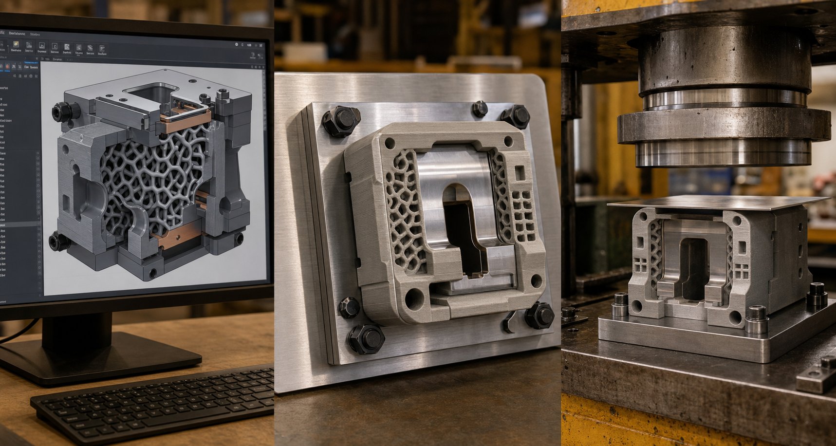
Knowing which materials and sheet metals work together is essential, but it won't help you until you actually produce a functional die and stamp a good part with it. The complete 3d printed die design workflow involves six distinct stages, each with decisions that directly affect whether your tooling survives production or fails on the first cycle.
- CAD design with additive-specific considerations
- Slicing and print parameter setup
- Printing the die
- Post-processing and dimensional verification
- Press setup and first article forming
- Die maintenance and replacement planning
Let's walk through each stage with the practical detail you need to get it right the first time.
CAD Design and Additive Manufacturing Considerations
When you approach cad design for stamping die work in an additive context, you're designing for two realities simultaneously: the forming operation and the printing process. Ignore either one, and you'll end up with a die that either can't be printed cleanly or can't survive press loads.
Wall thickness and mass. Polymer stamping dies need substantially more bulk than you might expect. Minimum wall thickness for FDM tooling should be 8–12 mm in load-bearing areas. Thin cross-sections below 2 mm deform rapidly under compressive load and heat, as Formlabs research confirms - surface thickness less than 1–2 mm will deform with heat in forming applications. For metal-printed dies, 3–5 mm wall sections typically provide adequate stiffness, since the material itself carries substantially higher loads per unit area.
Draft angles. Include 3–5 degrees of draft on all vertical walls of the die cavity. This serves dual purposes: it facilitates part ejection after forming (preventing the sheet metal from locking in the die) and improves printability by reducing overhangs that need support structures. For polymer dies especially, draft angles reduce the demolding forces that can chip or crack the tool surface.
Reinforcement strategies. Polymer dies rarely work as standalone monolithic tools under press loads. Design your die to integrate with a backing plate - typically an aluminum or steel plate that distributes force across the die's rear face. Plan recesses or bolt holes in your CAD model for fastening the printed die to this backing structure. Some designers embed steel dowels or bolts within the print by pausing mid-print and inserting hardware, creating a composite tool that handles far more load than polymer alone.
Infill pattern for 3d printed tooling. This is where internal geometry decisions directly determine die life. Three patterns dominate tooling applications:
- Gyroid: Provides near-isotropic strength, meaning it resists forces roughly equally in all directions. Gyroid's continuous curved geometry also offers excellent resistance to shear forces. For stamping dies that experience off-axis loads or complex forming geometries, gyroid at 60–80% density is the default recommendation.
- Cubic: Creates a three-dimensional grid structure that excels at vertical compression resistance. If your forming load runs primarily straight down through the die (simple V-bends, channel forms), cubic infill at 50–70% density provides strong performance with less material than gyroid at equivalent strength.
- Grid: The simplest and fastest-printing pattern, with perpendicular lines forming squares. Grid handles direct vertical compression well, but performs poorly under shear or off-axis loads. Use it only for flat-bottomed dies with purely compressive loading - never for dies with angled forming surfaces.
For most stamping die applications, gyroid at 70% infill density or higher gives you the best combination of compressive strength and consistent performance across load directions. Going to 100% infill is rarely worth the added print time - research shows diminishing strength returns above 60–80% density, while print time increases linearly.
Stock allowance. Plan extra material (0.5 mm minimum) on critical forming surfaces. You'll remove this during post-processing to dial in final dimensions. It's far easier to sand or machine away extra material than to reprint an undersized die.
Printing Parameters and Post-Processing
With your CAD model optimized, slicing settings translate those design intentions into physical reality.
Layer height: Use 0.1–0.15 mm layers for forming surfaces that contact sheet metal. Finer layers mean smoother surfaces and better dimensional accuracy, both of which transfer directly to formed part quality. For non-critical areas (backing faces, mounting surfaces), 0.2–0.3 mm layers speed things up without penalty.
Print orientation: Orient the die so that forming loads compress layers together rather than trying to peel them apart. For a V-die, this means printing with the forming cavity facing up and layers stacking parallel to the die face. Layer delamination under tensile loads is the most common failure mode in FDM tooling - proper orientation prevents it.
Perimeter count: Increase outer wall layers to 4–6 perimeters minimum. These solid outer shells carry the majority of compressive loads and protect internal infill from direct contact with the sheet metal. More perimeters also improve surface durability.
Post processing 3d printed dies bridges the gap between raw print and functional tool:
- Support removal and cleanup: Remove all support material, paying special attention to forming surfaces. Any remaining nubs or marks will telegraph into your formed parts.
- Surface finishing: Sand forming surfaces through progressive grits - 120 to 220 to 400 - to eliminate layer lines. For polymer dies, an epoxy coating on the forming surface creates a harder skin that resists wear longer. For SLA dies, media blasting with glass beads smooths the surface and can actually improve mechanical properties.
- Dimensional verification: Measure critical dimensions with calipers or a CMM. Compare against your CAD model and note deviations. Typical dimensional accuracy for FDM tooling runs ±0.1–0.3 mm; SLA achieves ±0.05 mm. If critical forming surfaces are out of spec, machine or sand them to tolerance using the stock allowance you planned earlier.
- Heat treatment (metal dies only): Metal-printed dies require stress relief and often age-hardening. Maraging steel, for example, needs aging at approximately 490°C for 6 hours to reach full hardness (50–55 HRC). Skip this step and your metal die will underperform significantly.
Press Setup and First Article Forming
Your die is printed, finished, and dimensionally verified. Getting it into the press correctly determines whether that first hit produces a good part or a destroyed tool.
Backing plate integration: Never place a polymer die directly on a press bed without a metal backing plate. The plate distributes ram force across the entire die footprint, preventing localized crushing. Use a ground flat aluminum plate at minimum 6 mm thick for low-tonnage applications, or a steel plate for anything above 10 kN. Secure the die to the backing plate with bolts, clamps, or a recessed pocket that prevents lateral movement during forming.
Alignment: Mount centering pins or use registration features printed into the die halves to ensure punch-to-die alignment. Misalignment as small as 0.5 mm causes uneven loading that accelerates die wear on one side and produces inconsistent parts.
Speed and force settings: Start conservatively. Reduce press speed to 50% of what you'd use with conventional tooling. Polymer dies don't tolerate impact the way hardened steel does - slower ram speeds allow the material to absorb forming loads progressively rather than experiencing shock. For the same reason, reduce tonnage to the minimum that achieves full forming, then increase incrementally if the part isn't fully shaped.
First article inspection: Form one part, remove it, and measure it against your target dimensions. Check for:
- Spring-back deviation (compare actual angle to target angle)
- Surface marks or scratches transferred from die layer lines
- Dimensional accuracy at critical features
- Any signs of die deformation (shiny spots, compression marks on the die surface)
If spring-back exceeds tolerance, adjust die geometry per the compensation strategies discussed earlier and reprint. If surface marks appear, additional sanding or coating resolves them. If the die shows compression marks after a single hit, your material choice or infill density isn't adequate for the forming forces involved - step up to a stiffer material class rather than reprinting at the same spec.
Maintenance cycle: Inspect the die surface every 10–20 parts for polymer tooling, every 500–1,000 parts for metal-printed dies. Wear patterns reveal themselves as surface dulling, edge rounding, or micro-cracks at stress concentrations. Light sanding between runs can extend polymer die life, while metal dies benefit from periodic polishing of forming surfaces. Track dimensional drift on your formed parts - when measurements approach tolerance limits, the die is approaching end of life.
This end-to-end process - design, print, finish, set up, form, maintain - typically compresses into 24–72 hours for polymer dies and 1–2 weeks for metal-printed dies including heat treatment. Compare that to 4–8 weeks for conventionally machined tooling, and the time advantage becomes clear. But speed only matters if the die actually lasts long enough to finish your production run, which raises the critical question of how these tools fail and what you can do to prevent it.
Die Lifespan and Failure Mode Analysis
Speed from CAD to first article is impressive, but none of it matters if the die crumbles halfway through your run. How long do 3D printed dies last? The honest answer: it depends entirely on how they fail, and every 3D printed die fails eventually through one of four predictable mechanisms. Understanding these stamping die failure modes - and designing around them - is what separates a successful short run from a pile of shattered plastic and rejected parts.
Common Failure Modes in 3D Printed Dies
Every additively manufactured die carries inherent weaknesses tied to the layer-by-layer build process. These weaknesses manifest as distinct failure patterns, each with different warning signs and different consequences for your formed parts.
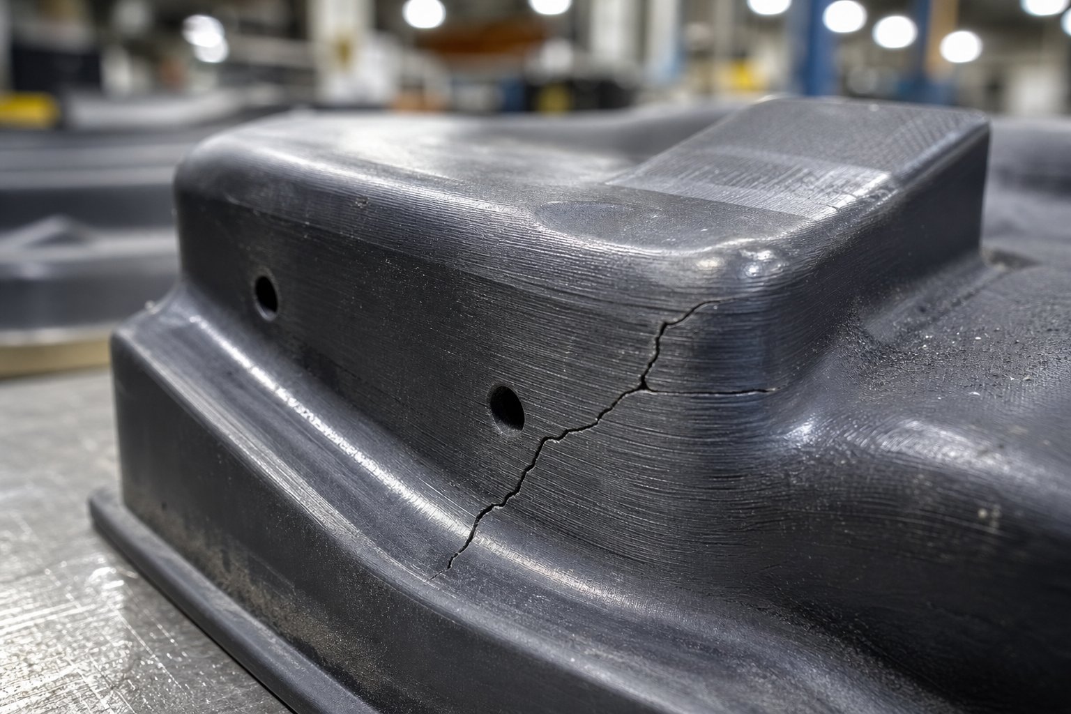
- Layer delamination under repeated compressive loads. This is the most common and most sudden failure mode in FDM polymer dies. Each printed layer bonds to the one below it through thermal fusion, but that bond is weaker than the bulk material itself. Repeated press cycles create cyclic compressive and tensile stresses at layer interfaces. Over time, micro-cracks nucleate along these boundaries and propagate until entire sections peel apart. Research on 3D-printed composite structures confirms that interlaminar tensile stress at layer boundaries drives delamination initiation - once the interlaminar tensile strength (ILTS) is exceeded, failure is sudden rather than gradual. You'll often hear a sharp crack, and the die splits along a layer line without prior warning.
- Surface wear degradation affecting part finish. Every stamping cycle involves sheet metal sliding against the die face under force. That sliding action gradually abrades the die surface, smoothing out fine detail and widening tolerances. In polymer dies, wear manifests as a polished sheen developing on high-contact areas, followed by dimensional loss as material is physically removed. Metal-printed dies resist this far longer but still degrade - particularly if surface finish from printing leaves micro-peaks that act as initial wear points.
- Thermal degradation from friction heat buildup. Friction between sheet metal and die surface generates heat with each press cycle. At production speeds, that heat accumulates faster than the die can dissipate it. Polymer dies are especially vulnerable because their heat deflection temperatures are relatively low - PLA softens at 55°C, ABS at 95°C, even CF-Nylon starts losing stiffness above 150°C. Once the die surface temperature approaches these thresholds, the forming surface deforms plastically under loads it previously handled fine. You'll notice formed parts getting progressively less accurate as the die "mushrooms" at high-contact points.
- Compression failure from exceeding material yield strength. This is the most straightforward failure: the forming force simply exceeds what the die material can resist. The die crushes, cracks, or permanently deforms on the very first hit or within the first few cycles. Unlike the other modes, compression failure isn't progressive - it's immediate and catastrophic. It happens when operators underestimate forming forces, use sheet metal thicker than the die was designed for, or skip backing plate integration.
These four modes don't operate in isolation. A die experiencing thermal softening will delaminate at lower loads. A die with surface wear develops stress concentrations that accelerate layer separation. In practice, most polymer dies fail through a combination - thermal softening weakens the structure, then delamination delivers the final blow.
Mitigation Strategies Through Design and Material Choice
Each failure mode responds to specific countermeasures. You can't eliminate failure entirely, but you can push it further out along the production timeline.
- Against delamination: Print orientation is your strongest defense. Orient dies so forming loads compress layers together rather than trying to separate them. Use gyroid infill at 70%+ density to distribute interlaminar stresses evenly. Increase perimeter shells to 5–6 walls, creating a thick solid boundary that resists crack propagation. For critical dies, consider continuous fiber reinforcement (CF-Nylon composites) - embedded carbon fibers bridge layer boundaries and dramatically increase interlaminar shear strength.
- Against surface wear: Apply a thin epoxy or urethane coating to polymer die forming surfaces. This hard skin takes the abrasion instead of the base material, and it can be reapplied between runs. For metal-printed dies, post-process with surface polishing to eliminate as-printed roughness peaks that accelerate initial wear. Consider shot peening metal die surfaces to induce compressive residual stress, which resists crack initiation at wear sites.
- Against thermal degradation: Slow down your press cycle. Adding even a few seconds between hits allows friction heat to dissipate. Use materials with higher heat deflection - CF-Nylon over plain nylon, nylon over ABS, ABS over PLA. For high-cycle-rate operations, integrate cooling pauses into your production sequence (stamp 10 parts, pause 30 seconds). Metal-printed dies largely eliminate this concern because tool steels maintain their properties well above any friction temperature generated during room-temperature stamping.
- Against compression failure: Always use a metal backing plate that distributes press force across the entire die footprint. Never exceed 60–70% of the die material's published compressive strength during operation - this safety margin accounts for the reduced strength of printed parts versus solid injection-molded or wrought equivalents. When in doubt, run a force calculation before your first press cycle: if required forming force exceeds 50% of your die's rated capacity, step up to a stronger material class.
Operational practices matter as much as design. Lubricate the sheet metal with a light stamping oil or dry-film lubricant to reduce friction forces and surface temperatures simultaneously. Inspect the die at regular intervals - every 10–25 cycles for polymer, every 500–1,000 for metal. Replace rather than repair polymer dies; they're cheap and fast enough to reprint that running a damaged tool risks scrapping formed parts.
Die Lifespan Expectations by Material Class
So how long do 3D printed dies last in real-world production? Here's what to expect across the material spectrum, assuming proper design, orientation, and operating practices:
| Die Material | Typical Lifespan (Forming Cycles) | Primary Failure Mode | Best Application |
|---|---|---|---|
| PLA | 5–30 parts | Thermal degradation / compression | Single prototype validation |
| ABS / PETG | 20–75 parts | Surface wear / delamination | Short proof-of-concept runs |
| Nylon (PA6/PA12) | 50–200 parts | Surface wear / delamination | Low-volume production |
| CF-Nylon Composite | 100–500 parts | Surface wear (gradual) | Functional low-volume tooling |
| SLA Rigid Resin | 5–20 parts | Brittle fracture / compression | Surface detail validation only |
| Metal-Printed Maraging Steel | 10,000–100,000+ parts | Surface wear (very gradual) | Medium-to-high-volume production |
| Metal-Printed H13 Tool Steel | 50,000–500,000+ parts | Fatigue cracking (very long term) | High-volume production |
These ranges assume forming thin-gauge aluminum or mild steel. Harder sheet metals reduce lifespan dramatically - forming stainless steel with a CF-Nylon die might yield only 10–30 parts before the surface degrades beyond acceptable tolerance. Protolabs reports that even for injection molds (a comparable loaded-tooling application), 3D-printed polymer tooling typically becomes ineffective within 100 shots, while metal tooling can reach 10,000 shots and beyond. Stamping dies face similar physics, though the load profile differs.
Die wear and durability ultimately come down to a production volume decision. Polymer dies make economic sense when you need fewer than 100–500 parts and can tolerate periodic reprinting. Metal-printed dies justify their higher upfront cost when volumes reach the hundreds or thousands, where a single print replaces dozens of polymer reprints. And conventional machined tooling remains the right answer for volumes exceeding 100,000 parts, where amortized cost per part drops below what any additive approach can match.
Knowing where your die will fail - and roughly when - transforms the 3D printed die lifespan question from guesswork into planning. You can schedule replacement prints, budget for material costs across an entire production run, and make an informed call about whether the per-part economics of additive tooling actually beat traditional methods. That cost-benefit comparison deserves a structured framework of its own.
Cost-Benefit Framework for Tooling Decisions
Failure mode knowledge tells you when a die needs replacing. But how many replacement cycles can you afford before the economics tip against you? The real question behind every 3D printed die cost vs traditional tooling debate isn't which method is cheaper per die - it's which method delivers your total production run at the lowest cost per formed part.
That calculation involves more variables than most people realize. Let's break it down.
Cost Factors in 3D Printed Versus Conventional Tooling
A stamping die cost comparison must account for six distinct cost drivers, not just the sticker price of the tool itself:
- Die material cost: A polymer FDM die might cost $5–30 in filament. An SLA die runs roughly $30 for in-house printing. A metal-printed die in maraging steel starts around $200–500+ depending on size and complexity. A conventionally machined tool steel die typically costs $450–2,000+ for equivalent geometry.
- Print or machining time: Polymer dies print in 10–24 hours. Metal-printed dies require 1–5 days plus heat treatment. Conventional machining and outsourcing takes 15–25 business days. Time is money when your production deadline is fixed.
- Post-processing labor: Sanding, coating, dimensional verification, and backing plate integration add 1–4 hours per polymer die. Metal-printed dies need stress relief, surface finishing, and possibly EDM - adding cost that can represent 15–40% of the total part cost for metal AM components.
- Press cycle time impact: Polymer dies require slower ram speeds to avoid shock loading, reducing throughput by 30–50% versus hardened steel tooling. Over hundreds of parts, that speed penalty adds up in labor and machine time.
- Die replacement frequency: A CF-Nylon die lasting 200 parts means five reprints for a 1,000-part run. Each replacement adds material cost, print time, and setup labor. A metal-printed die covers that same run without replacement.
- Opportunity cost of lead time: Waiting 4–6 weeks for conventional tooling means delayed revenue, missed market windows, or idle assembly lines. A die printed overnight lets you start forming tomorrow. For time-critical projects, that speed advantage can outweigh a higher per-part cost.
Production Volume Breakeven Analysis
The breakeven analysis for metal stamping dies follows a predictable pattern. 3D printing has near-zero setup cost but roughly linear cost scaling - 50 parts cost about 50 times one part. Conventional tooling has high fixed cost but rapidly declining per-unit cost as that investment spreads across more parts. The crossover depends on your die material class and replacement rate.
Here's how the economics shift across volume tiers for low volume stamping tooling cost scenarios:
| Production Volume | Polymer FDM Die | Metal-Printed Die | Conventional Machined Die | Lowest Cost Option |
|---|---|---|---|---|
| 1–10 parts | $35–60 total (1 die) | $300–600 total (1 die) | $500–2,000+ total (1 die) | Polymer FDM |
| 10–100 parts | $50–150 (1–2 dies) | $300–600 (1 die) | $500–2,000 (1 die) | Polymer for under 50; metal-printed above 50 |
| 100–1,000 parts | $150–900 (3–10 dies) | $300–600 (1 die) | $500–2,000 (1 die) | Metal-printed or conventional |
| 1,000+ parts | Not practical (too many replacements) | $300–600 (1 die, may need 1 replacement) | $500–2,000 (1 die, lasts entire run) | Conventional (lowest cost per part) |
Notice the crossover zone between 50 and 200 parts. Below that range, polymer dies dominate because the die itself costs so little that even multiple replacements stay cheaper than a single conventionally machined tool. Above that range, conventional tooling's durability means zero replacement cost, and the high fixed investment gets diluted across enough parts to drop below additive per-part economics.
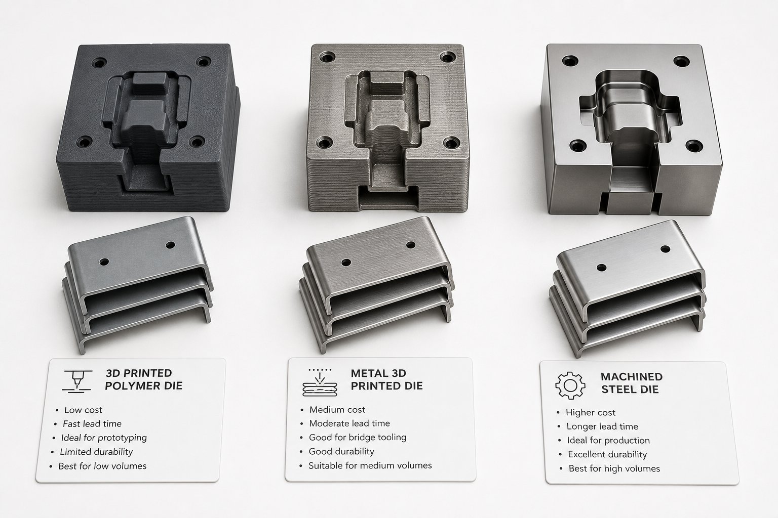
Metal-printed dies occupy a strategic middle ground. They cost more upfront than polymer but eliminate the replacement cycle that erodes polymer economics at higher volumes. For runs of 100–10,000 parts, they often represent the sweet spot - durable enough to avoid replacement, fast enough to avoid the 4–6 week lead time of conventional machining, and capable enough to handle forming forces that polymer can't sustain.
The math changes further when you factor in design instability. If your part geometry might change after the first 50 pieces, sinking $1,500 into conventional tooling becomes a liability. A $30 polymer die that you can reprint with updated geometry overnight carries almost no risk if the design evolves. That flexibility premium doesn't show up in a simple per-part cost calculation, but it's real - especially during product development cycles where validation and iteration happen in parallel.
Ultimately, cost analysis alone doesn't capture the full picture. The most practical strategy often combines methods: polymer dies for initial geometry validation and first-article testing, then a metal-printed or conventional die once the design stabilizes for production. That staged approach minimizes both financial risk and lead time - validating the concept cheaply before committing serious tooling investment.
Rapid Prototyping Strategies for Part Validation
A staged approach - polymer dies first, then production tooling - only works if you can actually confirm the part is right before committing budget. That's where part validation before production tooling becomes the real gatekeeper. Printing a die and forming a few pieces tells you whether the geometry is physically achievable. It doesn't necessarily tell you whether the part fits an assembly, meets spec under load, or can be manufactured at scale without costly revisions.
Validating a stamped component requires more than a single method. It requires the right combination of methods applied at the right stage of development.
Using 3D Printed Dies for Part Validation
3D printed dies excel at one specific validation task: proving that a given sheet metal geometry can be formed, that spring-back can be compensated, and that the blank develops correctly. When you prototype sheet metal forming with an in-house polymer die, you're answering questions about formability - can this shape be stamped without tearing, wrinkling, or excessive spring-back?
That's genuinely valuable. It catches design problems that would otherwise surface only after expensive production tooling is built. Teams can validate stamping die design iteratively, reprinting adjusted dies in hours and testing multiple geometry revisions in a single day. For early-stage concept work, nothing else matches this speed.
But formability validation has limits. A part formed on a polymer die may differ dimensionally from the same part formed on hardened steel tooling - different surface friction, different elastic deflection of the die itself, different thermal behavior. The formed prototype confirms approximate geometry, not production-exact dimensions. For fit checks in tight assemblies, tolerance-critical interfaces, or functional testing under real loads, you need parts produced with methods closer to final production conditions.
Integrating Multiple Rapid Prototyping Methods
Rapid prototyping metal stamped parts works best as a progression rather than a single step. Each method covers a different validation need:
- 3D printed dies (in-house): Validate formability, spring-back behavior, and blank development. Fast, cheap, ideal for geometry exploration.
- CNC-machined prototypes: Produce parts from solid stock that match final dimensions exactly. Useful for fit checks, assembly validation, and functional testing where material properties must match production intent.
- Sheet metal fabrication (laser cutting + press brake): Create parts using actual production-grade sheet metal and forming processes. Confirms manufacturability with real materials and provides parts suitable for environmental or load testing.
- DFM feedback: Expert review of part geometry against stamping process constraints - bend radii, grain orientation, draw depth limits - before tooling investment locks the design.
Teams that combine these methods catch problems at the cheapest possible stage. A formability issue caught with a $30 printed die saves the $1,500 conventional tool revision. A fit problem caught with a CNC-machined prototype saves weeks of production delay. Early DFM feedback prevents both.
For product-development teams that need professional-grade validation beyond what in-house 3D printed tooling can achieve, YICHEN's rapid prototyping services bridge the gap between concept validation and production commitment. By combining rapid CNC prototyping, sheet metal fabrication, and early DFM feedback in a single workflow, YICHEN helps teams validate metal stamped parts with production-representative accuracy - confirming form, fit, and function before full tooling investment begins.
This layered validation approach doesn't just reduce risk. It builds confidence that the design you're about to tool for production is actually the design you want - not one that will need emergency revisions after the first pilot run. The remaining question is how to decide which path your specific project needs.
Choosing the Right Tooling Path for Your Project
Every tooling decision comes down to a handful of variables: how many parts you need, how fast you need them, how stable your design is, and how tight your tolerances must be. Rather than treating 3D printed vs conventional stamping dies as an either-or choice, think of them as different tools for different stages. Here's a tooling decision framework manufacturing teams can apply immediately.
When 3D Printed Dies Are the Right Choice
Knowing when to use 3d printed stamping dies saves both time and budget. They fit cleanly into these scenarios:
- Geometry validation: You need to confirm a stamped shape is physically achievable before investing in production tooling.
- Low volume production (under 100–500 parts): The per-part economics favor printing over machining when replacement frequency stays manageable.
- Design instability: Your part geometry is still evolving, and reprinting a $30 die beats reworking a $1,500 machined tool.
- Time-critical projects: You need formed parts tomorrow, not in four to six weeks.
- Soft metals at thin gauges: Aluminum, copper, or mild steel under 0.8 mm - materials that stay within polymer die load limits.
- Educational or hobbyist work: Budget and accessibility matter more than production-grade durability.
These are genuine low volume metal stamping solutions that deliver real parts without the financial commitment of conventional tooling. The key is recognizing their limits honestly - and knowing when your project has outgrown them.
When to Invest in Professional Tooling Support
3D printed dies validate concepts. Production demands something more. If any of these conditions apply, it's time to step beyond in-house additive tooling:
- Design is finalized and volumes exceed 500–1,000 parts.
- Tolerances tighter than ±0.2 mm are required on formed features.
- Sheet metal is stainless steel, high-strength steel, or thicker than 1.0 mm mild steel.
- Parts must pass functional or environmental testing with production-representative accuracy.
- Assembly fit checks require exact dimensional conformance across mating components.
For teams in this position, YICHEN's rapid prototyping services provide the logical bridge between 3D printed die prototyping and full production tooling commitment - combining rapid CNC prototyping, sheet metal fabrication, and early DFM feedback to validate parts with production-grade accuracy before you commit serious capital. That early DFM review alone can prevent the costly tooling revisions that plague teams who skip validation and jump straight to production dies.
The smartest path usually isn't one method or the other - it's a progression. Start with a 3D printed die to prove formability. Validate fit and function with professional prototyping. Then commit to production tooling with confidence that the design is locked. That staged approach minimizes both financial risk and time-to-market, giving you formed parts at every stage without gambling your tooling budget on unverified geometry.
Frequently Asked Questions About 3D Printed Metal Stamping Dies
1. How many parts can a 3D printed stamping die produce before failing?
Die lifespan varies dramatically by material class. PLA dies typically last 5-30 parts before thermal degradation or compression failure. Nylon and CF-Nylon composites extend that to 50-500 parts under proper conditions. Metal-printed dies in maraging steel can handle 10,000 to 100,000+ forming cycles, while H13 tool steel dies printed via DMLS may reach 500,000 cycles. These figures assume thin-gauge aluminum or mild steel as the workpiece - harder sheet metals reduce lifespan significantly.
2. Can you use a 3D printed die to stamp stainless steel?
Polymer 3D printed dies cannot reliably form stainless steel at any practical gauge. Stainless steel's high yield strength (200-290 MPa in annealed condition) combined with aggressive work-hardening generates forming forces that exceed polymer compressive capacity. Metal-printed dies produced from maraging steel or H13 tool steel via laser powder bed fusion can stamp stainless steel effectively. Research at Oakland University demonstrated that coated 3D-printed metal inserts successfully stamped 50,000 parts from ultrahigh-strength steel without significant surface degradation.
3. What infill pattern is best for 3D printed stamping dies?
Gyroid infill at 70% density or higher is the recommended default for most stamping die applications. Its continuous curved geometry provides near-isotropic strength, resisting forces equally in all directions and handling shear loads well. Cubic infill works for dies with purely vertical compressive loading like simple V-bends, while grid pattern should only be used for flat-bottomed dies with no off-axis forces. Going above 80% infill density shows diminishing strength returns relative to the added print time.
4. Is a 3D printed die cheaper than a machined stamping die?
For production runs under 100 parts, polymer 3D printed dies cost roughly $35-150 total including replacements, compared to $500-2,000+ for conventionally machined tooling. The breakeven point typically falls between 50 and 200 parts depending on die material and replacement frequency. Metal-printed dies ($300-600) occupy a middle ground, becoming cost-effective for 100-10,000 part runs where they eliminate both the replacement cycle of polymer dies and the long lead time of conventional machining. Beyond 10,000 parts, conventional tooling usually wins on per-part economics.
5. How do you compensate for spring-back when using 3D printed dies?
Spring-back compensation requires over-bending the die geometry so the sheet metal relaxes back to the target angle after press release. The fastest approach with polymer dies is iterative: print, form a test part, measure actual spring-back deviation, adjust the CAD model by that amount, and reprint. Since polymer dies cost only a few dollars and print in hours, multiple iterations are practical. For metal-printed dies, validate spring-back compensation in polymer first, then commit the corrected geometry to a metal print. High-strength materials may need die angles of 73-78 degrees to overcome significant elastic recovery.


