
How Metal Stamping Dies Manufacturers Turn Your Design Into Tooling
What Metal Stamping Dies Manufacturers Do and Why It Matters
When you're sourcing precision parts at scale, one question tends to surface early: what is dies in manufacturing? The answer shapes every decision downstream, from material selection to production volume targets. Understanding stamping dies and the manufacturers who build them gives you a clearer path from concept to finished component.
What Are Metal Stamping Dies
A stamping die is a custom-engineered precision tool that cuts and forms sheet metal into functional shapes by applying force through a stamping press.
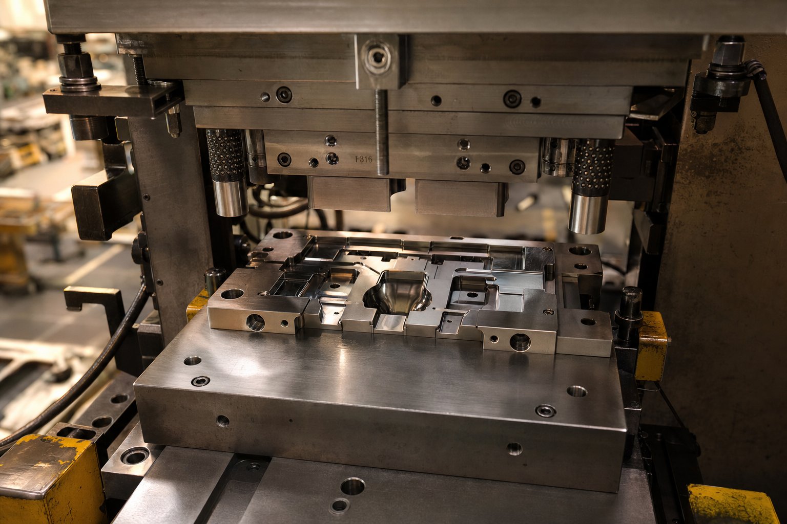
Unlike generic tooling or off-the-shelf fixtures, metal stamping dies are purpose-built for a specific part geometry. Each die consists of upper and lower halves that work together inside a press, performing operations like cutting, bending, piercing, drawing, and forming. The two halves align through hardened guide pins and bushings, ensuring repeatable accuracy across thousands or even millions of press cycles.
Think of a stamping die as the negative image of your finished part. Every contour, hole, and flange in your design corresponds to a precisely machined feature in the tool. That level of customization is exactly what separates custom metal stamping dies from commodity punch-and-die sets you might find in a catalog.
What Metal Stamping Dies Manufacturers Actually Do
A metal stamping dies company overview that stops at "they make tools" misses the full picture. These manufacturers function as engineering partners across the entire tooling lifecycle. Their scope typically includes:
- Feasibility analysis and design-for-manufacturability feedback
- CAE simulation to predict material flow and springback
- CNC machining, wire EDM, and precision grinding of die components
- Heat treatment and surface finishing for wear resistance
- Assembly, dry-run verification, and iterative press tryout
- Ongoing maintenance, sharpening, and repair services
Each metal stamping die goes through this progression before it ever produces a production part. The manufacturer's job is to translate your design intent into robust tooling that holds tolerance run after run. That means catching potential issues during simulation rather than discovering them on the press floor, where changes cost exponentially more.
This article walks through the full process, from die types and construction materials to evaluation criteria and working relationships. Whether you're an engineer specifying tolerances, a sourcing manager comparing suppliers, or a manufacturer exploring new stamping dies for an upcoming program, the sections ahead give you the context to make sharper decisions.
Types of Stamping Dies and How to Match Them to Your Project
Choosing the right die type is one of the earliest decisions in any stamping program, and it directly shapes tooling cost, cycle time, and part quality. Yet many buyers reach the RFQ stage without a clear sense of which approach fits their geometry, volume, and budget. The four primary types of stamping dies each solve a different production problem. Understanding where each excels helps you have a more productive conversation with your tooling partner from the start.
Progressive Dies for High-Volume Continuous Runs
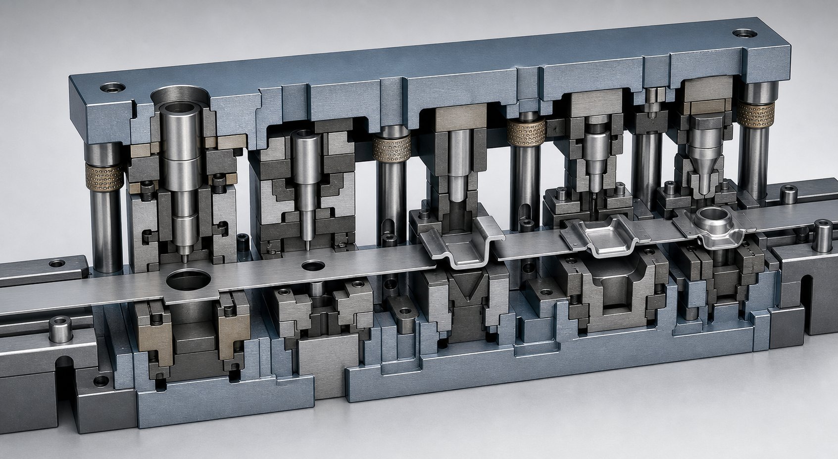
Imagine a strip of metal feeding into a die and emerging as a finished part a fraction of a second later. That's progressive die stamping in action. A coil of strip stock enters one end, advancing incrementally through a series of stations, each performing a distinct operation such as piercing, bending, coining, or trimming. By the final station, a completed component is separated from the carrier strip.
Progressive dies are the workhorse choice for high-volume programs producing complex parts. Because the material never leaves the die between operations, cycle times stay short and part-to-part consistency remains high. Progressive die manufacturers typically recommend this approach when annual volumes exceed tens of thousands of pieces and part geometry involves multiple features that would otherwise require separate operations.
The tradeoff is upfront investment. Designing and building a progressive die requires meticulous planning across every station, and modifications after construction can be costly. But for long production runs, the per-piece cost drops dramatically, often making progressive dies the most economical option over the life of a program.
Transfer Dies for Larger or Deeper Parts
Some parts simply can't travel through a progressive die on a carrier strip. Deep-drawn shells, large brackets, and components with geometry that extends beyond the flat plane of the stock material need a different strategy. Transfer dies solve this by separating the blank from the strip at the first station, then mechanically moving it between independent forming stations using grippers or transfer fingers.
This independence is what gives transfer die stampings suppliers the flexibility to handle parts that are too large, too deep, or too geometrically complex for strip-feed approaches. Each station can perform aggressive draws, flanges, or re-strikes without being limited by the material connecting the part to the strip. An added benefit: eliminating the carrier web reduces material usage per part, which can meaningfully lower piece cost on programs using expensive alloys.
Transfer dies carry higher tooling and setup costs, and cycle times are slightly longer than progressive setups because of the mechanical transfer motion. They're best justified for medium-to-high volumes where part size or depth makes progressive tooling impractical.
Compound Dies for Flat Precision Parts
When your part is relatively flat and demands tight dimensional accuracy across all features, a compound die delivers results in a single press stroke. Compound dies perform multiple cutting and forming operations simultaneously. Piercing and blanking happen at the same instant, which ensures perfect alignment between internal features and the outer profile.
This simultaneous action makes compound dies well-suited for washers, electrical laminations, terminal blanks, and other precision flat components where concentricity or positional accuracy is critical. They're simpler in construction than progressive or transfer tooling, which keeps initial costs moderate. However, they're limited to parts without complex 3D forming, and production speed is lower than progressive stamping for high-volume needs.
For engineers evaluating metal press dies for flat components at low-to-medium volumes, compound dies often deliver the best balance of precision and cost. They also serve as excellent first-operation tooling, producing blanks that feed into subsequent forming processes.
Single-Station Dies for Simple Operations
Not every stamping job requires multi-station complexity. Single-station dies perform one operation per press stroke, whether that's a blank, a pierce, a form, or a trim. They're the most straightforward stamper dies to design and build, making them ideal for prototyping, short runs, or secondary operations on parts that have already gone through primary stamping.
The simplicity of single-station tooling means fast turnaround and low upfront cost. The downside is efficiency. Producing a part that requires multiple operations means handling it through several dies, increasing labor and potentially introducing positional variation between operations. For production programs, single-station dies are typically reserved for low-complexity parts or situations where a custom die stamp solution for one specific feature is all that's needed.
Comparing Die Types at a Glance
The table below maps each die type against the factors that matter most during project planning. Use it to narrow your options before engaging a manufacturer for detailed feasibility analysis.
| Die Type | Best Use Case | Typical Production Volume | Part Complexity | Material Thickness Range | Relative Tooling Cost |
|---|---|---|---|---|---|
| Progressive | Complex multi-feature parts at high speed | High (50,000+ annually) | Medium to high | 0.1 mm - 6 mm | High |
| Transfer | Large, deep, or 3D-formed parts | Medium to high (10,000+) | High | 0.5 mm - 12 mm | High |
| Compound | Flat precision parts with tight tolerances | Low to medium (1,000 - 50,000) | Low to medium | 0.1 mm - 4 mm | Medium |
| Single-Station | Simple operations, prototypes, short runs | Low (under 10,000) | Low | 0.1 mm - 10 mm | Low |
Notice how volume and part complexity push you toward different ends of the spectrum. A flat connector terminal at 500,000 pieces per year points squarely at progressive tooling, while a deep-drawn enclosure at 20,000 units annually is a textbook transfer die application. Matching the die type to your project's actual requirements, rather than defaulting to the most familiar option, is one of the fastest ways to control tooling investment without sacrificing part quality.
Of course, the die type only tells part of the story. The materials used to build that tooling, from tool steel grades to surface treatments, determine how long it holds tolerance and how much maintenance it demands over its service life.
Die Construction Materials That Separate Good Tooling from Great
Two dies can look identical on the outside and perform very differently over 500,000 cycles. The difference usually comes down to what they're made of. Stamping die steel selection is one of the clearest indicators of a manufacturer's engineering depth, yet it rarely appears in RFQ comparisons. Understanding which tool steel grades, carbide options, and surface treatments apply to your project helps you evaluate whether a quoted price reflects long-term value or just low upfront cost.
Tool Steel Grades Used in Stamping Die Construction
Most steel stamping dies are built from a handful of proven tool steel grades, each optimized for a specific balance of hardness, toughness, and wear resistance. Here's where the common grades fit:
D2 is the go-to cold-work grade for blanking and forming dies that face abrasive wear. Its high carbon and chromium content delivers excellent wear resistance at hardness levels around RC 58-60, making it well-suited for long production runs on mild steel and HSLA sheet. The tradeoff is moderate toughness. D2 can chip or crack under heavy impact loading.
A2 offers a middle ground. It's an air-hardening grade with better toughness than D2 while still providing good wear resistance. When your sheet metal stamping dies need to handle both forming severity and moderate impact, A2 strikes a practical balance for medium-to-high volume programs.
S7 is a shock-resisting grade built for impact. If your die experiences heavy blanking forces, aggressive cam actions, or repeated shock loading, S7 absorbs that energy without catastrophic failure. It won't match D2 for abrasion resistance, but it keeps running where brittle grades would fracture.
M2 is a high-speed steel that retains hardness at elevated temperatures. It's typically reserved for punch tips and cutting inserts in high-speed progressive dies where friction-generated heat would soften conventional cold-work steels.
The right choice depends on your production volume, the workpiece material being stamped, and the dominant failure mode the die will face. A manufacturer stamping soft aluminum stampings at moderate volumes might specify A2, while one running 1.5 million cycles on high-strength steel would lean toward D2 or a powder metallurgy alternative with even finer carbide distribution.
Carbide Inserts and Surface Treatments
When standard tool steels reach their limits, carbide stamping dies components extend service life significantly. Tungsten carbide inserts are common in cutting stations where abrasive sheet metals, coated steels, or high-strength alloys would wear through conventional steels in a fraction of the expected die life. These inserts are brazed or mechanically retained in the die body, concentrating extreme hardness exactly where the wear occurs.
Surface treatments add another layer of protection without changing the die's base geometry. The most common options include:
Nitriding (gas or plasma ion) diffuses nitrogen into the tool surface, creating a hard case that resists adhesive wear and galling. Ion nitriding is faster, operates at lower temperatures, and minimizes the brittle white layer that can flake under load.
TiN and TiAlN coatings applied via physical vapor deposition (PVD) produce a high-hardness, low-friction surface. Research documented by the AHSS Application Guidelines shows PVD-coated tools producing over 1.2 million parts compared to just 50,000 for chrome-plated equivalents on the same sheet metal die application.
Chrome plating, once an industry default, is falling out of favor. It can exhibit microcracking under high contact pressures typical of advanced high-strength steels, and environmental regulations are tightening around the process.
A practical approach many manufacturers use: build the die body from cost-effective cast iron or lower-grade steel, then install high-grade tool steel or carbide inserts at wear-critical locations. This targets investment where it matters most and keeps overall tooling cost in check.
How Die Material Affects Part Quality and Cost
Material selection doesn't just determine how long a die lasts. It directly affects the parts coming off the press. A die surface that degrades introduces burrs, dimensional drift, and surface imperfections into your stamped components. Over time, these quality issues translate into scrap, rework, and potential line stoppages downstream.
Higher-grade stamping die steel holds tighter tolerances longer between sharpening intervals. Coated surfaces reduce friction, which improves material flow and minimizes galling marks on finished parts. For engineers specifying sheet metal stamping dies, asking the right questions about die material before approving a build is one of the most effective ways to protect part quality across the full production run.
Here are the key factors to discuss with your manufacturer during material selection:
- What is the expected die life in strokes before regrind, and what steel grade supports that target?
- What is the dominant failure mode for this application: abrasive wear, adhesive wear, chipping, or cracking?
- Does the workpiece material (high-strength steel, stainless, aluminum) require carbide inserts or coatings?
- Will surface treatments be applied before or after tryout, and how does that affect dimensional allowances?
- What is the maintenance interval assumption built into the quoted die life?
- Are powder metallurgy tool steels justified for the production volume and workpiece strength involved?
These questions shift the conversation from price-per-die to cost-per-part, which is the metric that actually drives your bottom line. A manufacturer who can articulate why they chose a specific grade for your application, rather than defaulting to whatever steel is in stock, signals the kind of engineering depth that pays dividends across hundreds of thousands of press cycles.
The Die Design and Engineering Process Explained Step by Step
Knowing what materials go into a die is valuable. But understanding how a design actually becomes validated production tooling gives you something more practical: a clear picture of the timeline, decision points, and collaboration involved when you engage a manufacturer. The stamping process in manufacturing moves through distinct engineering phases, and each one exists to catch problems early, when fixes are inexpensive and fast.
Here's the full progression a metal stamping die design follows, from your initial part file to production-approved tooling.
- Part feasibility analysis and material evaluation
- Strip layout and process planning
- CAE simulation and forming validation
- Detailed die design and component engineering
- CNC machining, EDM, and component fabrication
- Assembly, alignment, and die fitting
- Press tryout, sample inspection, and iterative refinement
- Production approval and handoff
Each phase builds on the one before it. Skipping or rushing any stage introduces risk that compounds further down the line. Let's look at the three major engineering stages in detail.
Feasibility Analysis and Material Selection
Before any design work begins, the manufacturer's engineering team conducts a gatekeeping review of your part. This feasibility analysis determines whether your geometry is stampable as drawn, and if not, what modifications improve manufacturability without compromising function.
What does this review actually cover? Engineers examine your part geometry looking for features that create forming challenges: bend radii that are too tight relative to material thickness, draw depths that exceed the material's ductility limits, holes positioned too close to bends where distortion would make them go oval, or features requiring tolerances that drive tooling cost disproportionately. An experienced engineer can identify these concerns quickly because they've seen similar geometries succeed or fail across thousands of prior programs.
Material evaluation runs in parallel. The sheet metal stamping process behaves differently depending on your chosen alloy's yield strength, ductility, and springback characteristics. A part designed in mild steel might stamp cleanly on the first tryout, while the same geometry in high-strength steel or stainless could wrinkle, split, or spring back beyond tolerance. The manufacturer assesses whether your material choice supports the intended geometry and suggests alternatives when it doesn't.
This is also where production volume enters the equation. A run of 5,000 parts per year justifies a different tooling strategy than 500,000. Volume influences die type selection, material grade for the tooling itself, and whether certain features should be formed in-die or handled in secondary operations. The best manufacturers treat this phase as a collaborative DFM conversation rather than a one-way quote exercise.
CAE Simulation and Die Design
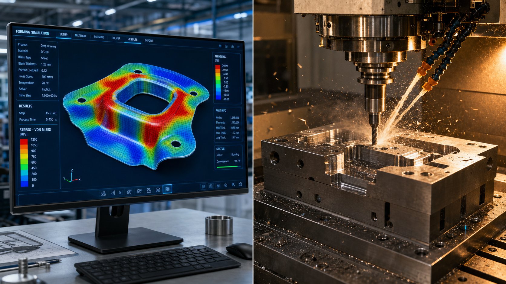
Imagine being able to stamp your part a hundred times digitally, watching exactly where the metal thins, wrinkles, or springs back, before a single block of tool steel is cut. That's what finite element analysis brings to the stamping manufacturing process.
Using platforms like AutoForm, DYNAFORM, or similar dedicated forming simulation software, engineers model the complete interaction between your sheet metal blank, the die surfaces, and the press forces. The simulation predicts material flow into die cavities, identifies regions of excessive thinning or compression, calculates springback magnitude, and flags potential splits or wrinkles. According to Keysight's analysis of forming simulation, this virtual validation allows manufacturers to detect and resolve potential defects before actual production begins, replacing expensive physical try-outs with iterative digital refinement.
Springback compensation is one of the highest-value outputs of simulation. Every material has a tendency to partially return toward its original shape after forming. Rather than discovering this on the press and re-machining die surfaces through trial and error, simulation quantifies the springback and allows engineers to build the necessary over-bend directly into the tool geometry from the start.
The detailed die design phase follows simulation validation. Engineers translate the proven forming concept into a complete 3D model specifying every component: punch profiles, die blocks, stripper plates, guide systems, pilot pin locations, and the strip layout that sequences operations across stations. This is where the die stamping machine requirements get defined too, including press tonnage, bed size, and shut height needed to run the finished tool. CAD platforms like SOLIDWORKS or Siemens NX generate the manufacturing drawings that feed directly into the machining phase.
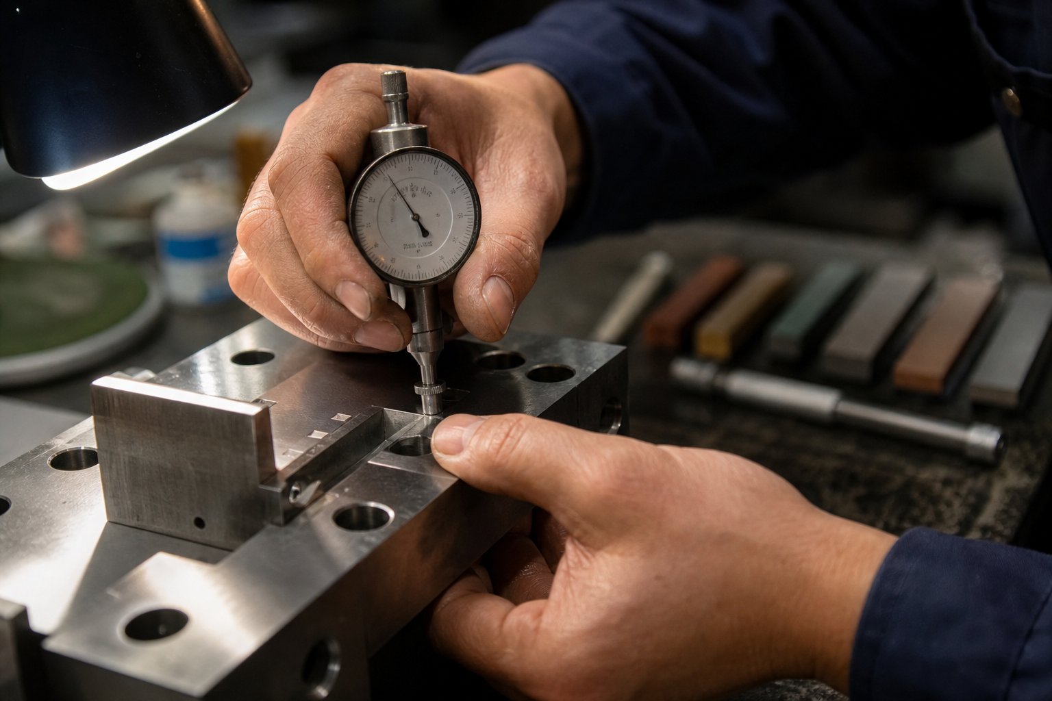
Machining, Assembly, and Tryout Validation
With the design finalized, fabrication begins. CNC milling machines produce the primary die forms, working from hardened tool steel blocks to create punch profiles, die cavities, and plate geometries to tight tolerances. Complex internal features, sharp internal corners, and fine details that would be difficult or impossible to mill get handled by wire EDM and sinker EDM, which use electrical discharge to erode material with micron-level precision.
Surface grinding brings critical surfaces to their final flatness and finish specifications. Heat treatment hardens working components to their target Rockwell values. The manufacturing stamping process for the tooling itself demands the same precision mindset that will eventually produce your parts.
Assembly brings all machined components together into the die set. Punches seat into the punch plate, die blocks mount to the lower shoe, guide pins and bushings align the halves, and spring systems get calibrated. Alignment at this stage is measured in microns. A slight misalignment between upper and lower halves would manifest as uneven cutting, premature wear, or out-of-tolerance parts.
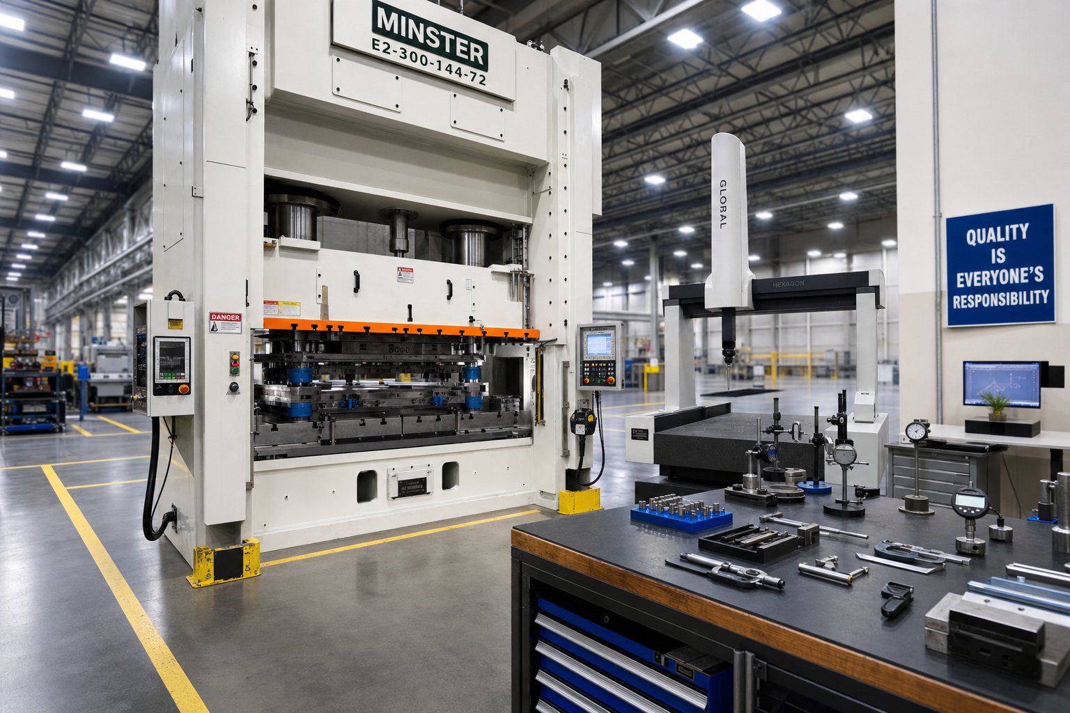
Tryout is where theory meets reality. The assembled die goes into a press and runs its first strokes on actual production material. Engineers inspect the resulting samples against your part print, measuring dimensions, checking surface finish, and evaluating edge quality. Almost no die produces perfect parts on the first hit. Iterative adjustments follow: a forming radius gets blended slightly, a cutting clearance gets tuned, a springback compensation gets dialed in more aggressively. Each iteration brings the samples closer to specification until dimensional conformance is confirmed across multiple consecutive runs.
This validation loop, running samples, measuring, adjusting, and re-running, is where experience separates capable manufacturers from the rest. A team that has validated thousands of dies recognizes patterns faster, makes more precise corrections, and reaches production approval in fewer iterations. The result: shorter lead times and lower development cost for you.
What you'll notice across this entire process is how heavily the early phases, feasibility, simulation, and detailed design, influence everything downstream. A thorough upfront engineering investment compresses the tryout timeline and reduces the chance of costly surprises. That same principle extends beyond individual die development into the broader question of which industries require what level of engineering rigor, and how their specific material and certification demands shape the tooling process from day one.
Industries Served and How Their Stamping Die Needs Differ
A stamping die built for an automotive body panel and one built for a micro-connector terminal may share the same fundamental physics, but that's where the similarities end. The materials, tolerances, volumes, and quality documentation required in each sector shape everything from tool steel selection to tryout validation criteria. Metal stamping dies manufacturers who serve multiple industries maintain distinct engineering playbooks for each, because a process that satisfies one sector's requirements can fall short in another.
Understanding these differences helps you evaluate whether a potential tooling partner has genuine experience in your industry or is simply listing it on a capabilities page.
Automotive Stamping Die Requirements
Automotive stamping dies operate in a world defined by volume, speed, and zero-defect expectations. A single vehicle platform might require hundreds of sheet metal stampings, from structural crossmembers and control arms to Class A body panels with cosmetic surface requirements. Annual volumes routinely reach hundreds of thousands or millions of pieces per part number, which means tooling must survive extreme cycle counts while holding tolerance throughout its service life.
What sets the automotive sector apart is its quality infrastructure. The IATF 16949 standard governs the entire automotive supply chain, demanding defect prevention rather than just detection. Unlike ISO 9001, which focuses on general customer satisfaction, IATF 16949 mandates the use of five core tools: APQP for launch planning, PPAP for production approval, FMEA for risk analysis, MSA for measurement validation, and SPC for real-time process monitoring.
For your automotive stamping die program, this translates to specific requirements at the tooling level. The die must produce parts that pass PPAP submission, meaning dimensional capability studies confirm process indices meet OEM targets across consecutive production runs. An automotive stamping die also needs to accommodate in-die sensing for real-time force monitoring, slug detection, and feed verification, because a single missed fault can send defective parts downstream before anyone catches the issue.
Tolerances for structural components typically land at +/-0.1 mm to +/-0.25 mm, while Class A panels demand even tighter surface profile controls to avoid visible waviness or sink marks after paint. The combination of high volumes, tight tolerances, and mandatory certification makes automotive one of the most demanding sectors for industrial metal stamping tooling.
Electronics and Electrical Component Stamping
Shift from a car door panel to an electrical connector terminal, and the scale of the challenge changes entirely. Parts shrink to millimeters. Material thickness drops below 0.2 mm. Tolerances tighten to microns. Yet production volumes often rival or exceed automotive numbers, with connector programs running into the tens of millions annually.
Electrical metal stamping requires progressive dies running at high speed, sometimes exceeding 1,000 strokes per minute, on thin-gauge copper alloys, phosphor bronze, or beryllium copper. The critical quality factor isn't just dimensional accuracy. It's edge condition. Connector manufacturers require burr-free edges because even a small burr can interfere with mating surfaces, compromise electrical contact, or create clearance issues in miniaturized housings.
Imagine a connector pin that's 0.5 mm wide. A burr measuring just 0.05 mm, invisible to the naked eye, can prevent proper insertion into its receptacle. That's why precision die and stamping operations for electronics demand cutting clearances optimized to the specific alloy and thickness, along with progressive die designs that maintain alignment across dozens of stations operating at extreme speed.
Material handling adds another layer of complexity. Thin copper strips are soft and easily deformed, so feed systems, pilot registration, and strip guidance must prevent buckling or misregistration. Plating requirements, whether the terminals need gold, tin, or nickel, also influence die design because selective plating often happens on the strip before stamping, meaning the die must avoid damaging pre-plated surfaces.
Custom precision stamping for electronics doesn't typically require IATF 16949, but many connector OEMs impose their own customer-specific quality requirements that rival automotive rigor. PPAP-style submissions and statistical process controls are common, particularly for automotive-grade connectors that bridge both sectors.
Aerospace and Medical Device Applications
Aerospace and medical device stamping share a common thread: the consequence of failure is catastrophic. A faulty aircraft bracket can lead to structural failure at altitude. A defective surgical instrument component can harm a patient. Both sectors respond to this risk with extensive traceability, documentation, and process validation requirements that fundamentally shape how tooling is designed and qualified.
Aerospace stamping involves exotic materials like titanium alloys (Ti-6Al-4V), Inconel 718, and high-strength stainless steels (15-5 PH). These materials resist forming, generate extreme tool wear, and spring back aggressively. Dies for aerospace components require premium tool steels or carbide inserts at cutting stations, and simulation work must account for the nonlinear behavior of these alloys. The governing quality standard is AS9100D, which builds on ISO 9001 but adds aerospace-specific requirements around configuration control, counterfeit part prevention, and first article inspection per AS9102.
Medical device stamping, governed by ISO 13485, introduces its own distinct challenges. Biocompatibility drives material selection toward 316L stainless steel, titanium Grade 23 (ELI), and cobalt chrome. Surface finish requirements for patient-contacting components can demand finishes of 8-16 Ra or better, achieved through electropolishing after stamping. Lot traceability for implantable components extends all the way to patient-level records, meaning every stamped part must link back to a specific material heat number, production shift, and inspection record.
Both sectors share one practical impact on die manufacturing: production volumes are typically lower than automotive or electronics, but documentation intensity is far higher. A die that produces 10,000 aerospace brackets per year requires the same validation rigor as one producing 500,000 automotive components, which affects the cost structure and timeline you should expect when sourcing tooling for regulated industries.
Industry Requirements at a Glance
The table below consolidates the key differences across sectors, giving you a quick reference for understanding what your industry demands from a tooling partner.
| Industry Sector | Typical Materials | Tolerance Range | Production Volume | Required Certifications |
|---|---|---|---|---|
| Automotive | Mild steel, HSLA, Advanced HSS, Aluminum (5xxx/6xxx) | +/-0.1 mm to +/-0.25 mm | High (100,000 - millions/year) | IATF 16949, ISO 9001 |
| Electronics/Electrical | Copper alloys, phosphor bronze, beryllium copper, brass | +/-0.01 mm to +/-0.05 mm | Very high (millions - tens of millions/year) | ISO 9001, customer-specific requirements |
| Aerospace | Ti-6Al-4V, Inconel 718, 15-5 PH stainless, 7075 aluminum | +/-0.05 mm to +/-0.13 mm | Low to medium (1,000 - 50,000/year) | AS9100D, NADCAP (special processes) |
| Medical Devices | 316L stainless, Ti Grade 23, cobalt chrome, PEEK | +/-0.025 mm to +/-0.13 mm | Low to medium (500 - 50,000/year) | ISO 13485, FDA 21 CFR 820 |
Notice how the certification column reveals something important about manufacturer selection. A tooling partner certified to IATF 16949 has proven systems for high-volume defect prevention, but that doesn't automatically qualify them for aerospace traceability or medical device validation. Conversely, a shop with AS9100 experience in exotic alloys may not have the high-speed progressive die expertise that electronics programs demand.
This is precisely why evaluating a manufacturer requires looking beyond their equipment list. The certifications they hold, the industries they've actually delivered tooling for, and the engineering support they provide during development all factor into whether they're the right fit for your specific program requirements.
How to Evaluate Metal Stamping Dies Manufacturers for Your Project
Knowing what your industry demands from tooling is one thing. Translating that into a shortlist of qualified metal stamping die manufacturers is a different challenge entirely. Online directories give you names and addresses. What they don't give you is a framework for determining which supplier actually has the capacity, certifications, and engineering depth to deliver tooling that works on the first production run.
Price comparisons only tell part of the story. Two stamping die manufacturers can quote the same project at similar numbers while offering vastly different levels of capability behind that quote. The evaluation criteria below help you distinguish between a partner who will collaborate through development and a shop that simply builds to print without catching upstream problems.
Technical Capabilities to Verify Before Sending an RFQ
Equipment determines what a manufacturer can physically produce. Before sending your part drawings, confirm that the shop's hardware matches your project requirements. Here's what each capability means for your tooling:
Press tonnage range dictates the size and material thickness of dies the manufacturer can try out in-house. A shop limited to 200-ton presses can't validate a die that requires 600 tons of forming force. If your part involves deep draws or high-strength steel, ask about their maximum capacity. Manufacturers with press ranges spanning 50 to 2,000 tons cover everything from micro-precision connectors to large structural panels.
Bed size constrains the physical dimensions of the die. A progressive die for a 400 mm-wide bracket needs a press bed that accommodates the full strip layout. Verify that the manufacturer's available bed sizes support your die footprint without crowding.
CNC and EDM capacity reflects machining precision. High-speed CNC milling centers produce primary die forms, while wire EDM and sinker EDM handle fine details, tight radii, and hardened components that can't be conventionally milled. A manufacturer without in-house EDM capability outsources these operations, which adds lead time and coordination risk.
In-house simulation tools separate engineering-driven die manufacturers from build-to-print shops. A manufacturer running forming simulation software like AutoForm or DYNAFORM can validate your die design digitally before cutting steel, catching springback issues, thinning risks, and material flow problems early. Without simulation, the tryout phase becomes longer and more expensive.
Material thickness limits define the working range. Some shops specialize in thin-gauge precision work under 1 mm, while others handle heavy-gauge structural stamping above 6 mm. Your part's thickness and material type should sit comfortably within the manufacturer's proven range, not at the edge of it.
When evaluating stamping press suppliers and die builders, don't just accept a tonnage number on a website. Ask what press models they operate, how many are available for tryout versus dedicated to production, and whether they can run your specific material at the required speed. Equipment utilization matters as much as equipment existence.
Certifications and Quality Systems That Signal Reliability
Certifications aren't just logos on a homepage. Each one represents an audited quality system with specific process controls. Matching the right certification to your industry requirement is essential.
ISO 9001 is the baseline. It certifies that a manufacturer operates a structured quality management system covering document control, calibration, nonconformance handling, and corrective actions. Any serious metal stamping die manufacturer should hold current ISO 9001 certification as a minimum. It doesn't guarantee perfect parts, but it confirms that controlled processes exist.
IATF 16949 builds on ISO 9001 with automotive-specific requirements: APQP launch planning, PPAP production approval, FMEA risk analysis, MSA measurement validation, and mandatory SPC. If your stamped parts feed into an automotive supply chain, your die manufacturer needs to understand and support these requirements, even if the certification resides with the stamping production facility downstream.
AS9100 adds aerospace-specific controls around configuration management, counterfeit part prevention, and first article inspection protocols. For aerospace tooling programs, verify that the manufacturer holds AS9100D and has delivered tooling into programs requiring AS9102 first article documentation.
A practical verification step: don't just accept a PDF certificate. Check the certificate number against the IAF CertSearch database to confirm validity, scope, and expiration. Some manufacturers hold certification for only a portion of their operations. Make sure the scope covers die design and manufacture, not just assembly or secondary services.
Evaluating Engineering Support and Communication
Equipment and certifications get you to a capable shortlist. Engineering support and communication are what separate a reliable partner from a competent but transactional shop. These softer factors often determine whether your project launches on time or stalls in development loops.
DFM feedback quality reveals how deeply a manufacturer engages with your design. A shop that simply quotes your drawing as-is might be building exactly what you asked for, including features that are unnecessarily expensive to tool or prone to forming issues. The best die manufacturers push back constructively, flagging opportunities to simplify geometry, relax non-critical tolerances, or consolidate operations. Research on DFM practices consistently shows that early collaboration between buyer and manufacturer can reduce tooling costs by 15-25% on average by eliminating unnecessary complexity before steel is cut.
Design iteration responsiveness matters because die development is inherently iterative. When simulation reveals a forming issue or tryout samples need adjustment, how quickly does the manufacturer communicate the problem, propose a solution, and implement the change? Ask potential suppliers about their typical response time for engineering questions and how many revision cycles their standard timeline accommodates.
Transparent project timelines protect you from schedule surprises. A professional stamping dies manufacturer provides a milestone-level timeline at the quoting stage, showing when design approval is needed, when machining starts, when tryout occurs, and when production samples ship. Vague timelines with a single delivery date and no intermediate checkpoints make it nearly impossible to identify delays before they cascade.
Use the checklist below when comparing die manufacturers side by side. It consolidates the technical, quality, and communication criteria into a single evaluation framework you can score during supplier assessment.
- Press tonnage range covers your die's forming force requirements with margin
- Bed size accommodates your die footprint without modifications
- In-house CNC and EDM capability for all critical die components
- Forming simulation software used during design validation
- Material thickness experience matches your part's gauge and alloy
- ISO 9001 certification verified and current
- Industry-specific certification (IATF 16949, AS9100) if applicable
- Documented DFM review process with written feedback
- Named engineering contact assigned to your project
- Milestone timeline provided at quotation with defined checkpoints
- References available from projects in your industry and volume range
- Clear tooling ownership and transfer terms stated in the agreement
- Maintenance and repair services available post-delivery
Scoring potential suppliers against these criteria gives you an objective comparison that goes well beyond quoted price. A manufacturer who checks every box at a slightly higher tooling cost will almost certainly deliver lower total project cost once you factor in development speed, tryout iterations, and long-term die performance.
With a qualified manufacturer identified, the next question becomes practical: what does the actual engagement look like from your first email to production-ready tooling sitting on the press?
From RFQ to Production-Ready Tooling
The gap between submitting an RFQ and receiving production-approved tooling is where stamping programs either gain momentum or stall. For many sourcing managers and engineers, that gap feels opaque. Knowing what information to provide upfront and what milestones to expect in return transforms the experience from uncertainty into a controlled, collaborative process.
Preparing an Effective RFQ for Stamping Tooling
A complete RFQ package accelerates everything downstream. Incomplete submissions force your stamping die supplier into assumptions, and assumptions lead to misquotes, redesigns, or tryout surprises. When preparing your request, include:
- 2D drawings with GD&T callouts and 3D CAD models (STEP or native format)
- Material specification including grade, temper, and thickness
- Annual volume estimate and expected program life
- Critical tolerances flagged separately from general block tolerances
- Surface finish requirements and any post-stamping processes (plating, painting, welding)
- Target piece price or tooling budget constraints, if known
One detail that consistently separates smooth programs from difficult ones: communicating the function of critical features. As documented by The Fabricator's DFM research, when a stamping die factory understands why a feature exists, it can suggest tolerance adjustments or geometry changes that reduce tooling cost by 20% or more without affecting part performance. A hole that locates a paint hook doesn't need the same positional tolerance as one that receives a press-fit pin.
The most effective way to compress die development timelines and reduce cost is thorough upfront communication. Every hour spent clarifying requirements before design begins saves days of rework during tryout.
What to Expect During Die Development and Validation
A professional dies manufacturing engagement follows a predictable milestone sequence. Here's the typical progression from purchase order to production release:
- Kickoff review: confirm part requirements, material, volumes, and timeline
- Feasibility feedback and DFM recommendations delivered within 1-2 weeks
- Design approval: manufacturer presents die concept, strip layout, and simulation results for your sign-off
- Machining and fabrication: CNC, EDM, grinding, and heat treatment of all die components
- Assembly and internal dry-run verification
- First tryout: initial samples produced and dimensionally inspected
- Iterative refinement: adjustments based on sample measurements until all dimensions conform
- PPAP submission or equivalent production approval documentation
- Production handoff: die ships to your press or production stamper
The PPAP stage deserves particular attention. As outlined by Fictiv's PPAP documentation, this process validates that your custom metal stamping die produces parts meeting all engineering specifications consistently, not just on a single good sample. It includes capability studies (CpK analysis), measurement system validation, process flow documentation, and a formal Part Submission Warrant confirming readiness for volume production.
Throughout this lifecycle, communication cadence matters. Industry experience shows that disciplined suppliers provide visibility into progress at each milestone rather than going silent between PO and delivery. A lack of communication during tooling build is often a warning sign of emerging delays. The best sheet metal stamping die partners proactively surface concerns, propose solutions, and keep your launch timeline intact.
For teams looking to experience this workflow with integrated engineering support from feasibility through inspection, YICHEN's stamping die solutions offer a full-service engagement model designed to move you from initial inquiry to manufacturing dies ready for production.
Of course, production approval isn't the end of the story. Once a die enters service, its long-term performance depends entirely on how well it's maintained, and knowing when to sharpen, repair, or replace tooling protects the investment you've made in development.
Stamping Die Maintenance and Maximizing Tooling Investment
A production-approved die represents months of engineering, machining, and validation work. Yet that investment only pays off if the tooling stays in condition across its intended service life. Stamping die maintenance is what separates tooling that delivers consistent parts for a million cycles from tooling that drifts out of tolerance after a fraction of its expected run.
Preventive Maintenance Schedules and Die Life Extension
Preventive maintenance works because it catches wear before it becomes damage. The logic is straightforward: scheduled cleaning, inspection, lubrication, and sharpening keep stamping die parts functioning within their design limits, so small issues never escalate into press stoppages or scrap events.
A practical PM schedule combines time-based intervals with stroke-count triggers. Per-shift checks cover visible debris, slug buildup, lubricant delivery, and obvious feeding problems. Weekly and monthly inspections go deeper into guide pins, springs, pilot condition, and cutting edge wear. Sharpening intervals, rather than following arbitrary calendars, should track actual hits per service based on the die's wear history and material being stamped. MetalForming notes that poorly scheduled PM can lead to over-maintenance, where components are replaced before they've degraded, or under-maintenance, where wear goes uncorrected until something breaks.
The purpose of bypass notches in stamping dies provides a useful wear indicator. These small reference features, machined into the die at a known depth, allow technicians to visually assess how much material has been removed through successive sharpening cycles. When a bypass notch disappears or reaches its limit, it signals that the section is approaching the end of its serviceable life and needs replacement rather than another regrind. Other wear indicators include burr height trending upward between sharpening intervals, guide pin scoring, and spring free-length reduction exceeding 10 percent.
For high-volume programs, metal stamping tooling benefits from tighter intervals as production intensity rises. Abrasive workpiece materials, critical tolerance requirements, and complex progressive die designs all accelerate wear and justify more frequent inspection points.
When to Repair, Refurbish, or Replace a Stamping Die
Stamping tool repair and routine maintenance serve different purposes. Industry analysis draws a clear distinction: maintenance preserves current condition, while repair restores something that's already damaged or no longer functioning correctly. Conflating the two leads to inflated maintenance budgets and hidden costs from unplanned downtime, expedited shipments, and quality spills.
The decision between repair, refurbishment, and replacement comes down to three factors: repair cost relative to replacement cost, production downtime during the fix, and whether the die can still achieve part tolerances after the work is done. A localized punch failure justifies component replacement. Cumulative clearance drift across multiple stations calls for reconditioning. But when records show repeated alignment loss, chronic dimensional instability after verified PM, or structural cracking that keeps returning, the stamping tooling has reached end of life and replacement becomes the economically sound decision.
Knowing which category your situation falls into requires evidence. Here are the warning signs that a die needs immediate attention versus items that belong on the next scheduled service:
- Immediate attention: chipping or cracking on cutting edges, sudden dimensional shift beyond tolerance, abnormal press noise or vibration, visible structural damage to die sections, slug pulling causing press jams
- Scheduled maintenance: gradual burr increase trending toward sharpening threshold, minor scoring on guide pins, spring force reduction within serviceable range, lubricant delivery decrease without part quality impact, bypass notch approaching limit
Track repair costs and downtime events by die, not in aggregate. That history reveals which tools respond well to routine care and which ones are consuming resources without delivering stable results. When the data consistently points toward instability despite proper maintenance, the most cost-effective path forward is engaging your tooling partner for replacement or redesign rather than continuing to fund diminishing returns on an aging tool.
Selecting the Right Stamping Die Manufacturing Partner
Maintenance history tells you when a die has reached its limits. But it also reinforces a broader point: the manufacturer you choose at the start of a program determines how well that tooling performs, how smoothly problems get resolved, and how much total value you extract from your investment. Choosing a partner isn't just about who builds the die. It's about who supports you across the full lifecycle of sheet metal stamping, from first feasibility conversation through years of production service.
Matching Manufacturer Type to Your Specific Needs
Not all die manufacturing companies operate the same way. They tend to fall into three categories, and matching the right type to your situation avoids misaligned expectations.
Full-service manufacturers handle everything from design and simulation through machining, tryout, and ongoing support. Some also run production stamping in-house, giving you a single source for both tooling and custom metal stampings. This model works best when you need integrated engineering support, want one accountable partner, or lack internal stamping expertise. The tradeoff is that you're consolidating risk with a single supplier, so vetting their capabilities thoroughly matters even more.
Tool-and-die-only specialists focus exclusively on building custom stamping dies without running production parts. They excel at complex tooling challenges and often invest more heavily in advanced machining, EDM, and simulation technology than shops that split resources between tooling and production. Choose this path when you already have a production stamper and need a dedicated tool & die manufacturing partner whose sole focus is tooling quality and precision.
Contract stampers with in-house tooling build the die and produce parts under one roof. This simplifies logistics and accountability for programs where the stamper owns the entire process. However, their tooling capability may be narrower than a dedicated stamping tool and die shop, since their primary business is running presses rather than engineering complex tooling from scratch.
Your decision depends on where your internal capabilities end. If you have strong engineering resources but no press capacity, a contract stamper makes sense. If you need deep DFM collaboration and advanced simulation before a single chip is cut, a full-service or dedicated tool & die manufacturing firm delivers more value during development.
Taking the Next Step Toward Custom Stamping Die Solutions
Everything covered in this article, from die types and construction materials to engineering process, industry requirements, and evaluation criteria, points toward one practical conclusion: the quality of your sourcing process determines the quality of your tooling outcome. Here's your action plan for moving forward:
- Define your requirements clearly: part geometry, material, annual volumes, tolerances, and surface finish documented before you contact anyone
- Verify technical capabilities against the evaluation checklist, confirming press tonnage, machining capacity, simulation tools, and material experience
- Request DFM feedback early and treat it as a qualification signal. Manufacturers who push back constructively on your design are demonstrating engineering depth
- Confirm certifications match your industry (ISO 9001 minimum, IATF 16949 for automotive, AS9100 for aerospace, ISO 13485 for medical)
- Ask for milestone timelines at the quoting stage so you can track progress and identify delays before they cascade
- Choose a partner that supports the full lifecycle: feasibility analysis, CAE simulation, precision machining, iterative tryout, dimensional inspection, and post-delivery maintenance
- Evaluate total cost of ownership rather than comparing tooling quotes in isolation
For teams ready to engage a full-service manufacturer that covers this complete workflow, YICHEN's stamping die solutions offer integrated engineering support from initial feasibility through production-ready tooling, designed to move you from research directly into an RFQ-ready engagement with confidence.
The right stamping tool and die partner doesn't just build what you ask for. They challenge your assumptions where it saves money, validate your design digitally before committing to steel, and stand behind the tooling long after it ships. That's the difference between buying a die and investing in a manufacturing relationship that compounds value across every production cycle.
Frequently Asked Questions About Metal Stamping Dies Manufacturers
1. What is dies in manufacturing?
In manufacturing, a die is a custom-engineered precision tool installed in a stamping press that cuts, bends, pierces, or forms sheet metal into a specific part shape. Unlike generic tooling, each stamping die is purpose-built for a single part geometry, consisting of matched upper and lower halves aligned by hardened guide pins. The die acts as the negative image of the finished component, reproducing its contours, holes, and flanges through controlled force application across thousands or millions of press cycles.
2. How do I choose between progressive, transfer, and compound stamping dies?
The choice depends on three factors: part geometry, production volume, and complexity. Progressive dies suit high-volume runs (50,000+ annually) for complex multi-feature parts that can remain on a carrier strip. Transfer dies handle larger or deeper parts that exceed strip-feed geometry limits, typically at medium-to-high volumes. Compound dies work best for flat precision parts requiring tight concentricity at low-to-medium volumes. A qualified manufacturer like YICHEN can assess your part file during feasibility analysis and recommend the optimal die type based on your specific requirements.
3. What certifications should a metal stamping die manufacturer hold?
At minimum, any serious manufacturer should hold current ISO 9001 certification. Beyond that, industry-specific certifications matter: IATF 16949 is required for automotive supply chains, AS9100D for aerospace programs, and ISO 13485 for medical device applications. Verify certificates against the IAF CertSearch database to confirm validity and scope. The certification scope should explicitly cover die design and manufacture, not just assembly or secondary services, ensuring the quality system applies to the actual tooling work performed on your project.
4. How long does it take to develop a custom stamping die from RFQ to production?
A typical stamping die development timeline runs 8 to 20 weeks depending on complexity, with key milestones including feasibility feedback (1-2 weeks after kickoff), design approval, machining and fabrication, assembly, tryout iterations, and PPAP submission. Progressive dies for complex automotive parts take longer than single-station tools for simple geometries. The biggest schedule variable is upfront communication quality. Providing complete RFQ packages with 3D CAD, GD&T drawings, material specs, and volume estimates compresses the timeline significantly by eliminating assumption-driven rework.
5. What factors affect the cost of a stamping die?
Stamping die cost is driven by die type (progressive costs more than single-station), part complexity and number of forming stations, tool steel grade and surface treatments selected, required tolerances, production volume expectations that dictate die life requirements, and the level of engineering support including simulation and DFM feedback. Evaluating cost on a per-piece basis over the full production run rather than comparing upfront tooling quotes in isolation gives a more accurate picture of total value, since higher-quality tooling typically delivers lower maintenance costs and fewer quality issues over its service life.


