


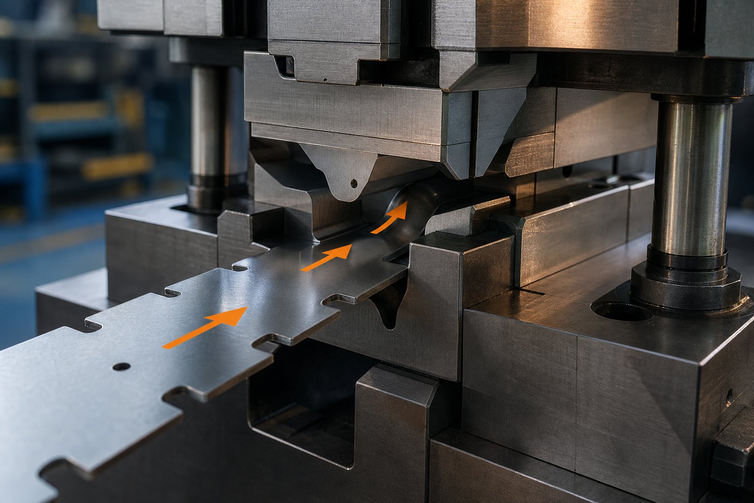
What Bypass Notches Do and Why They Matter in Stamping Dies
When you hear someone ask "what is metal stamping," the short answer involves converting flat sheet metal into three-dimensional parts using dies and presses. But the real engineering challenge lives in the details, specifically in controlling how material moves during forming. That is exactly where bypass notches come into play.
What Are Bypass Notches in Stamping Dies
A bypass notch is an intentional cutout designed into the periphery of a strip or blank that regulates how sheet metal flows into a stamping die cavity during forming. Think of it as a gate that controls traffic. Without it, material rushes into the forming zone unevenly, creating defects that ruin the finished part.
A bypass notch is a deliberate relief cut in the strip edge or blank boundary that controls material inflow, prevents die interference, and enables predictable metal distribution during stamping operations.
These notches serve a dual purpose in a stamping die. First, they manage carrier strip advancement in progressive dies by creating clearance so previously formed features can pass through subsequent stations without collision. Second, they govern draw-in behavior during forming by limiting how much material feeds into the die cavity from specific directions. The stamping definition of a bypass notch, then, goes beyond a simple cutout. It is a flow-control device engineered into the strip layout from the earliest design stage.
Why Material Inflow Matters for Part Quality
Imagine pulling a tablecloth toward the center of a table from all sides at once. Some areas bunch up, others stretch thin. The same thing happens in a stamping operation when material inflow is uncontrolled. You get wrinkling where excess material compresses, tearing where it stretches too far, and uneven wall thickness that compromises structural integrity.
Deep-drawing operations require carefully balanced holding forces to control material flow into the die cavity. The force must be low enough to allow draw-in yet high enough to prevent wrinkling. Bypass notches give engineers a geometric tool to complement those forces. By selectively removing material at specific locations along the strip edge, they dictate where and how much sheet metal enters the forming zone. The result is predictable strain distribution, consistent wall thickness, and parts that meet dimensional tolerances without excessive trial and error.
Understanding what is a stamping process without grasping material flow control is like learning to drive without understanding steering. The purpose of bypass notches in stamping dies is fundamentally about precision, giving the engineer directional authority over metal movement so that every formed feature comes out right.
How Bypass Notches Differ from Other Notch Types
Strip layout prints for sheet metal stamping dies can show half a dozen different notch features, and they all look like small cutouts at first glance. The confusion is understandable. Each notch type serves a distinct purpose, though, and mistaking one for another during die process planning leads to tooling errors that show up as scrap parts on the shop floor.
Bypass Notches vs Relief Notches vs Pilot Notches
Every notch in a stamping die exists to solve a specific problem. Relief notches reduce stress concentration at bend lines so the material folds cleanly without cracking. Pilot notches create openings that accommodate pilot pin entry for precise strip registration from station to station. Clearance notches prevent interference between adjacent stations, keeping formed features from colliding with tooling as the strip advances. Bypass notches, by contrast, specifically regulate material inflow during forming or allow strip sections to pass through stations without engagement.
The critical distinction is function. When you look at what are dies in a progressive configuration, you'll notice that pilot and pitch notches deal with strip positioning, while bypass notches deal with how metal behaves during the forming stroke itself. A pitch notch (sometimes called a French notch) is cut away from one or both strip edges to provide a solid stop that prevents overfeeding. A bypass notch, however, is engineered to control or interrupt material flow into a draw cavity.
| Notch Type | Primary Function | Typical Location | Effect on Material Flow |
|---|---|---|---|
| Bypass Notch | Controls material inflow into forming zones or allows strip to pass stations without engagement | Strip edge adjacent to draw or form stations | Directly restricts or redirects metal movement into the die cavity |
| Pitch (French) Notch | Provides solid stop to prevent overfeeding and aids strip registration | One or both strip edges at beginning stations | Minimal direct effect; primarily a feeding and location feature |
| Relief Notch | Reduces stress concentration at bend lines to prevent cracking | Corners and intersections of bend features | Localized stress relief; does not govern bulk material movement |
| Pilot Notch | Accommodates pilot pin entry for accurate strip positioning | Carrier strip or scrap areas between parts | None; serves only as a registration feature |
| Clearance Notch | Prevents formed features from interfering with adjacent tooling | Near previously formed geometry in downstream stations | Indirect; removes material that would otherwise collide with die components |
You'll notice that only the bypass notch has a direct, intentional influence on how metal distributes during the forming stroke. The other stamping die components related to notching focus on strip handling, registration, or stress management rather than active flow control.
Identifying Bypass Notches in Die Documentation
On a strip layout print, bypass notches typically appear as hatched or shaded cutout zones along the strip edge, positioned specifically adjacent to forming stations. They are distinguished from pitch notches by their location in the die process sequence. Pitch notches show up at the first or second station and are annotated with progression distance callouts. Bypass notches appear at or near draw and form stations, and their annotations reference material flow direction or forming depth rather than feed length.
Common annotation conventions include dimension callouts for notch depth and width, sometimes expressed as a ratio to material thickness. Engineers often label them with notes such as "bypass" or "flow control notch" on the strip layout, along with arrows indicating the direction of restricted draw-in. In more detailed documentation for types of stamping dies with complex forming sequences, you may find bypass notch specifications on a separate process sheet that ties each notch to a specific forming simulation result.
When reviewing die assembly drawings, look for bypass notch details near the draw ring or binder surface views rather than near the feeder-end stations. That positional context is the fastest way to tell them apart from pitch or pilot features, even before reading the annotation text.
Knowing which notch does what keeps the conversation between design, build, and tryout teams grounded in the same language. That shared understanding becomes especially important when you start exploring how each notch type physically interacts with the sheet metal at the grain level during forming.
The Physics of Material Inflow Control at Bypass Notches
A notch on a strip layout print is just a shape. But during the forming stroke, that shape fundamentally changes how metal behaves at the grain level. Understanding the physics behind bypass notches in sheet metal forming separates engineers who design notches by trial and error from those who get them right on the first tryout.
Metal Behavior at the Notch Boundary During Draw
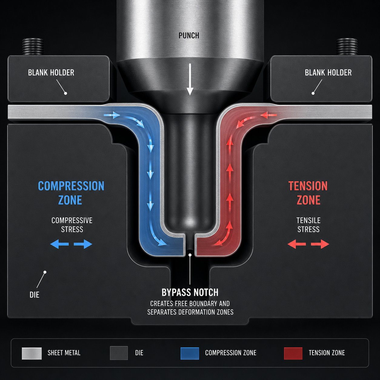
Picture a continuous blank edge feeding into a draw cavity. Along that uninterrupted edge, the material transmits tensile hoop stress from one region to the next. Every section of the flange pulls on its neighbor, creating a connected stress field that drives material inward toward the punch. Compressive circumferential stress builds up simultaneously, and when it exceeds the material's buckling threshold, wrinkles form.
A bypass notch interrupts that continuous edge. It creates a free boundary, a point where stress transmission simply stops. The metal on one side of the notch can no longer "communicate" mechanically with the metal on the other side. At the grain level, this means the crystallographic structure on each side deforms independently. Compressive forces that would have accumulated across the full flange width are now confined to smaller, more manageable zones.
This interruption does two things at once during the metal stamping process. It relieves the compressive buildup that causes wrinkling by shortening the unsupported flange length. And it prevents excess draw-in from distant regions that would otherwise thin the wall beyond acceptable limits. The notch boundary essentially acts as a strain barrier, isolating one flow zone from the next so each section draws material only from its own local reservoir.
How Notch Depth and Position Govern Strain Distribution
Deeper notches create more complete isolation between adjacent material zones. A shallow notch reduces stress transmission but does not eliminate it entirely because the remaining ligament still carries some load between zones. A deeper notch, one that extends further into the flange, narrows that ligament until each zone behaves almost as an independent blank during the stamping process.
Position matters just as much as depth. A notch placed at a transition between a deep-draw region and a shallow-form region prevents the high draw forces in one area from starving the adjacent area of material. Engineers working with negative and positive bypass notches in sheet metal forming stamping dies use position to target specific strain concentrations revealed by forming simulation or circle-grid analysis.
The mechanical effects of properly placed bypass notches include:
- Reduced wrinkling tendency due to shorter unsupported flange segments
- Controlled wall thinning by limiting how far material draws from each zone
- Uniform material distribution across complex part geometries
- Minimized springback variation because strain gradients stay consistent across regions
These effects combine to produce stamped metal parts with predictable dimensional accuracy and consistent mechanical properties. Without bypass notches governing flow at the boundary level, the same part geometry would require significantly higher binder forces or more aggressive draw beads to achieve equivalent results, often at the cost of increased tool wear and reduced material utilization.
The physics are clear: notch geometry directly controls strain distribution. But translating that principle into actual tooling dimensions, choosing the right depth, width, radius, and profile shape, requires a structured design approach that accounts for both part geometry and material behavior.
Bypass Notch Geometry and Design Parameters
Knowing that notch geometry controls strain distribution is one thing. Specifying the exact dimensions for a production stamping die design is another challenge entirely. Every geometric variable you choose, depth, width, shape, and corner radius, shifts the balance between too much material inflow and too little. Get the geometry wrong, and you trade wrinkles for splits or vice versa.
Notch Shape and Depth Relative to Material Thickness
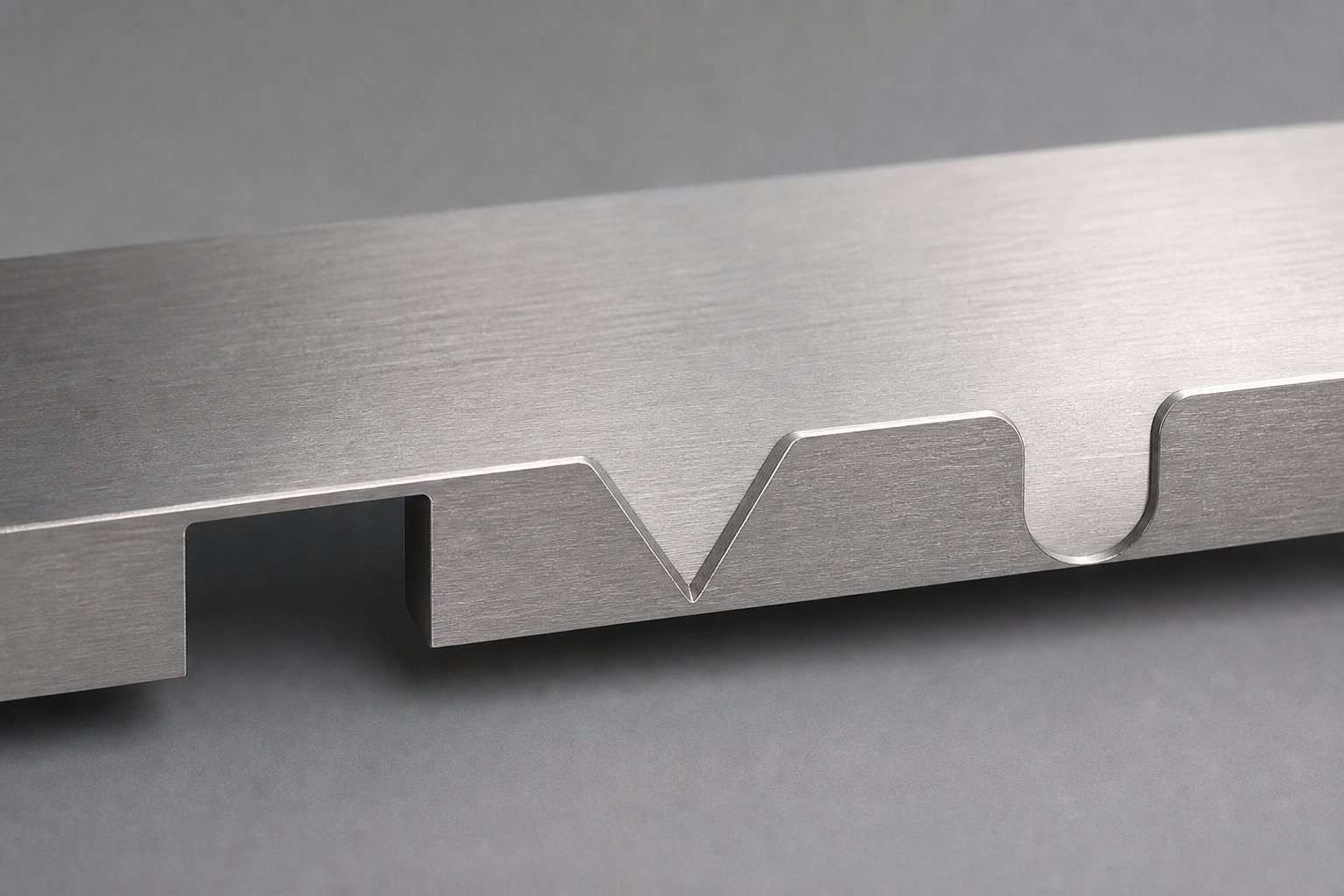
Three notch profiles dominate metal stamping die design practice: rectangular, V-shaped, and radius-ended (sometimes called slot-end or U-shaped). Each creates a different gradient of flow restriction at the strip edge.
- Rectangular notches produce an abrupt transition from full material to no material. They deliver maximum flow restriction at minimum notch width, making them efficient where space on the strip is limited. The tradeoff is higher stress concentration at the notch corners.
- V-shaped notches create a gradual restriction gradient. Material flow tapers as the notch widens toward its base, giving engineers finer control over how quickly inflow diminishes across the forming zone. The notch angle directly governs this gradient: a narrow V restricts flow sharply, while a wide V produces a gentler transition.
- Radius-ended notches combine the space efficiency of a rectangular profile with reduced stress concentration at the corners. The rounded ends resist crack initiation during forming, making them a common choice for higher-strength materials.
Notch depth is typically specified relative to draw depth or strip width. A general starting point in stamping design places notch depth between 50% and 100% of the local draw depth. Shallow notches restrict flow partially, allowing some material transmission across the boundary. Deeper notches approach full isolation, creating independent deformation zones as discussed in the physics section above.
Dimensional Tolerances and Sizing Guidelines
Sounds complex? It helps to break the sizing decisions into individual parameters, each with its own design logic. The table below organizes the key geometric variables that tooling engineers must control when specifying bypass notch dimensions for metal stamping design applications.
| Parameter | Design Consideration | Effect on Material Flow |
|---|---|---|
| Notch Width | Minimum 1.5 to 2 times material thickness to prevent shear-induced cracking during blanking | Wider notches interrupt a larger section of the flange edge, reducing inflow from a broader zone |
| Notch Depth | Typically 50% to 100% of local draw depth; deeper for full zone isolation | Controls how completely adjacent zones are decoupled; deeper notches eliminate cross-zone material transmission |
| Corner Radius | Minimum radius of 0.5 times material thickness to prevent crack initiation at notch roots | Larger radii distribute stress over a wider area, reducing edge cracking without significantly altering flow restriction |
| Depth-to-Width Ratio | Generally kept below 3:1 to maintain punch strength and prevent notch tool breakage | Higher ratios create narrow, deep cuts that isolate zones sharply but risk tooling failure and burr formation |
| Notch Angle (V-type) | Angles between 30 and 90 degrees depending on desired flow gradient | Narrower angles create steeper flow restriction; wider angles produce gradual transitions suited to shallow draws |
| Position Tolerance | Typically held within plus or minus 0.1 mm to maintain consistent flow behavior across production runs | Positional shift moves the strain boundary, potentially causing localized thinning or wrinkling on one side |
These values serve as starting points. Actual dimensions depend on part geometry, material grade, and forming simulation results. The key principle is that every parameter interacts with the others. A deep notch with sharp corners in a high-strength material will crack, while a shallow notch with generous radii in a soft material may not restrict flow enough to matter.
Positive vs Negative Bypass Notches
When engineers discuss negative and positive bypass notches sheet metal stamping dies, the distinction comes down to which direction the notch geometry extends relative to the nominal strip edge.
Negative bypass notches remove material inward from the strip edge. The notch cuts into the carrier or blank boundary, reducing the local strip width. This is the more common configuration because it requires only a simple punch operation to create the cutout. Negative notches work well when the strip layout provides enough carrier width to absorb the material removal without compromising feeding stability.
Positive bypass notches add material outward beyond the nominal strip edge. Rather than cutting in, the blank or strip is developed with extra material extending past where the edge would otherwise be. During forming, this added material acts as a local reservoir that feeds into the die cavity in a controlled manner. Positive notches are preferred when the strip is already at minimum carrier width and no further material can be removed without weakening the strip.
The choice between negative and positive bypass notches in a sheet metal stamping die depends on three factors: available strip width, required carrier strength for feeding, and the direction of material flow you want to encourage or restrict. In practice, many complex progressive die layouts use a combination of both types at different stations to balance flow control with strip integrity throughout the forming sequence.
Geometry alone does not determine how a bypass notch performs in production. The same dimensions behave differently in mild steel than in aluminum or stainless steel, which is why material properties must factor into every notch sizing decision.
How Material Type Affects Bypass Notch Design Decisions
A 2 mm deep rectangular notch that works flawlessly in mild steel can crack a stainless steel strip or fail to restrict flow in a soft copper alloy. Material properties, specifically yield strength, work hardening rate, and ductility, dictate how aggressively you can notch and still maintain a clean edge through production. Choosing bypass notch geometry without considering the specific alloy is like sizing a brake system without knowing the vehicle weight.
Steel Grades and Their Notch Design Implications
Mild steel (typically in the range of 200 to 300 MPa yield strength) behaves predictably during steel sheet stamping operations. Its relatively low yield point and high elongation mean the material flows readily into the die cavity, and standard notch depths of 50% to 100% of draw depth work as expected. Cold rolled mild steel offers a uniform grain structure that responds consistently to notch placement, making it the easiest material to develop bypass notch parameters for during initial die tryout.
High-strength low-alloy (HSLA) steels and Advanced High-Strength Steels (AHSS) change the equation significantly. These grades resist draw-in more because of their elevated yield and tensile strengths combined with substantially higher work hardening rates. When you are stamping steel in the 400 to 800 MPa range, the material does not want to move as freely into the die cavity. The result is that equivalent flow control often demands wider or deeper notches compared to mild steel. Bypass notches in AHSS also require careful attention to edge quality because these grades show increased sensitivity to edge-initiated fractures. The AHSS Forming guidelines specifically note that bypass notches placed in stretch or compression edges can act as stress risers, leading to edge fractures during draw or flange operations.
Stainless steel adds another variable: high work hardening. Austenitic grades like 304 harden rapidly during forming, which means the material stiffens as it flows past the notch boundary. Notch depths may need to be slightly greater than for equivalent-strength carbon steels, and corner radii should be generous to prevent the hardened edge from initiating cracks under the high forming loads typical of stamped steel components.
Aluminum and Copper Alloy Considerations
The aluminum stamping process presents a different set of challenges. Aluminum alloys generally have lower elongation at fracture compared to mild steel, and many tempered grades (like 6061-T6) are particularly prone to edge cracking. This means bypass notch design must be more conservative: shallower depths, wider notch widths, and notably larger corner radii to distribute stress away from the notch root.
Grain direction interacts strongly with notch orientation in aluminum. A notch cut perpendicular to the rolling direction places the notch tip stress concentration along the weakest fracture path. Rotating the notch alignment or choosing alloys with better cross-grain ductility (like 5052-H32) can reduce cracking risk without sacrificing flow control. Springback is also more pronounced in aluminum, so notch-induced strain boundaries may shift slightly after the forming stroke, something that rarely matters in steel but can affect dimensional accuracy in aluminum panels.
Copper alloys sit at the opposite end of the spectrum. High ductility and low work hardening mean the material flows easily, sometimes too easily. Less aggressive notch geometry is typically sufficient because even a modest notch creates meaningful flow restriction in a material that offers little resistance to draw-in on its own. The risk with copper is not cracking at the notch but rather insufficient flow control if notch depth is undersized.
The following material-specific adjustments help guide bypass notch design across common alloy families:
- Mild steel: Standard notch depths and corner radii; focus on position accuracy rather than edge condition
- HSLA and AHSS: Increase notch depth 10% to 25% over mild steel values; use radius-ended profiles to reduce edge fracture risk; maintain tight burr control at notch edges
- Stainless steel: Generous corner radii (minimum 1x material thickness); account for rapid work hardening by slightly increasing notch depth; polish notch edges to prevent crack initiation
- Aluminum alloys: Reduce notch depth to 40% to 70% of draw depth; increase corner radii to minimum 1.5x material thickness; align notches with rolling direction when possible to avoid cross-grain fracture
- Copper alloys: Shallower notches sufficient for flow control; standard corner radii acceptable due to high ductility; monitor for excessive draw-in rather than cracking
Each material demands that you validate notch geometry through forming simulation or prototype tryout before committing to production tooling. The parameters above serve as starting points, not final dimensions. Real-world confirmation becomes even more critical when you consider that bypass notch placement strategy varies not just by material, but by die type and station sequence in the overall strip layout.
Bypass Notch Placement Strategy in Progressive Die Layouts
Material choice tells you how aggressive your notch geometry can be. But where that notch sits in the strip layout, and at which station it gets cut, determines whether it actually solves the flow problem or creates a new one. Placement strategy is where strip layout engineering, forming sequence logic, and stage tooling decisions converge into a single coordinated plan.
Strip Layout Strategy and Station Sequencing
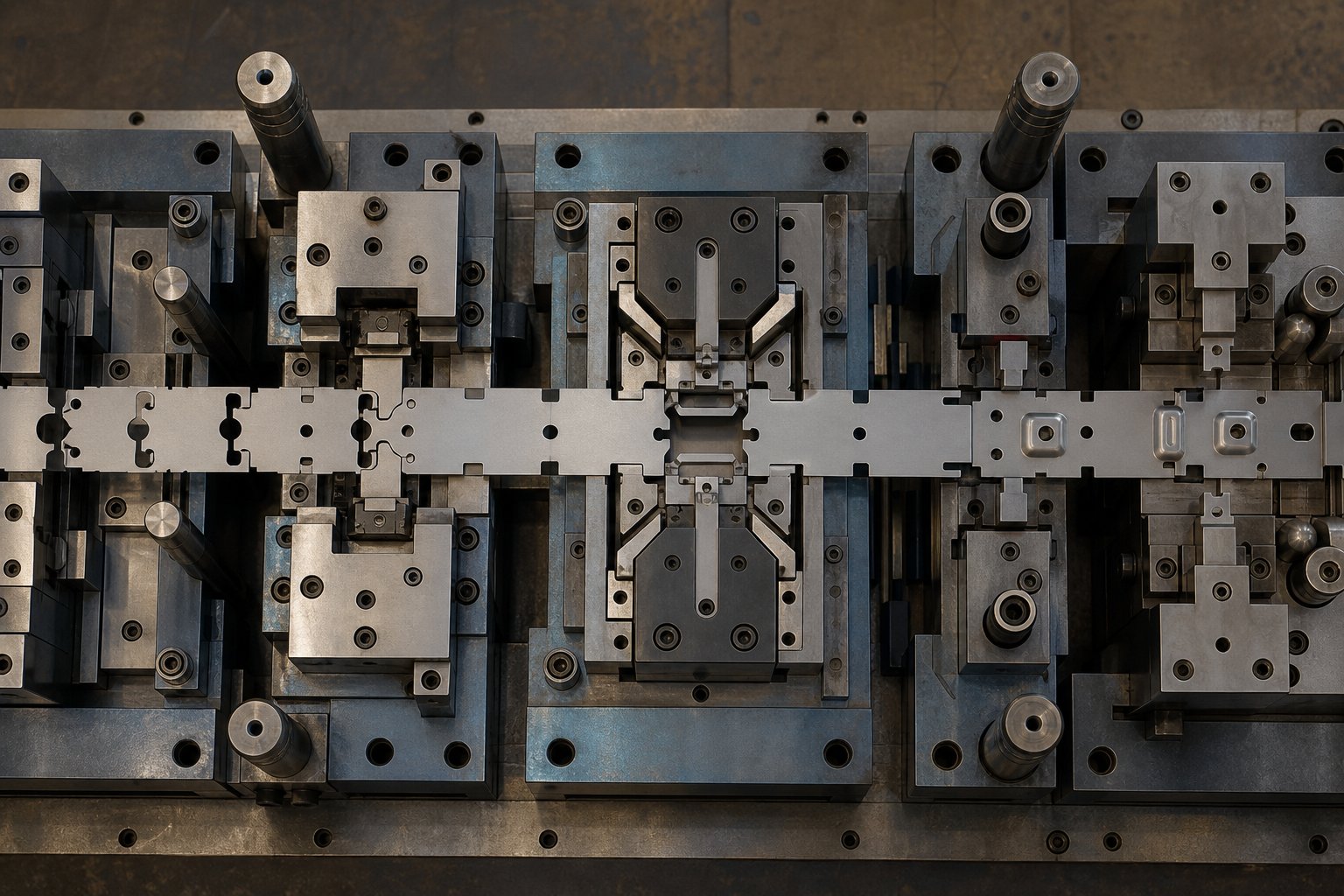
Bypass notch placement starts with a simple question: which stations need localized material flow control, and which stations must the strip pass through without interference? Engineers answer this by mapping the entire forming sequence and identifying two categories of need.
The first category is carrier strip management. In progressive stamping dies, the strip must advance through every station without previously formed features colliding with punches, pressure pads, or forming inserts. Bypass notches cut at earlier stations create clearance so that raised flanges, embossed features, or trimmed profiles can travel downstream safely. These notches are sized for clearance, not flow control. Their depth and width are driven by the height and footprint of the formed feature they need to accommodate.
The second category is forming flow control. Here, the notch actively restricts or redirects material movement during the draw or form stroke. Placement depends on which flange regions experience excess inflow (causing wrinkles) or insufficient inflow (causing splits). Engineers typically identify these regions through forming simulation, then position notches at stations immediately preceding or coinciding with the forming operation.
The sequencing logic follows a straightforward rule: cut the bypass notch as early in the strip progression as possible without weakening the carrier for upstream operations. Cutting too late means the material has already been committed to a stress state that the notch cannot correct. Cutting too early risks destabilizing the strip before it reaches critical forming stations. Most strip layouts place bypass notch cutting operations one to three stations ahead of the forming station they serve.
Progressive Dies vs Transfer Dies vs Single-Station Applications
The die type fundamentally changes how bypass notches function. In progressive metal stamping dies, notches serve the dual role of strip clearance and flow control because the part remains attached to a carrier strip throughout the process. Every station the strip passes through is a potential interference point, so notch placement must account for the full downstream journey.
Transfer stamping works differently. The blank is separated from the strip early, then mechanically transported between stations as a free part. Bypass notches in transfer dies focus almost exclusively on blank-edge flow control during individual forming operations. There is no carrier strip to manage, so the clearance function disappears entirely. The notch geometry becomes purely about governing how material at the blank periphery feeds into the draw cavity.
Single-station dies represent the simplest case. A single blank enters, one forming operation occurs, and the part exits. Bypass notches here are designed directly into the blank development shape, positioned based on forming simulation output with no multi-station sequencing to consider.
Automotive stamping dies often use transfer configurations for large body panels, where bypass notch placement along the blank edge controls material draw-in across complex curvatures. Smaller automotive brackets and connectors, by contrast, run in progressive dies where notch placement must balance both flow control and strip advancement through dozens of stations.
| Die Type | Notch Function | Typical Placement | Design Complexity |
|---|---|---|---|
| Progressive Die | Dual role: carrier strip clearance and forming flow control | One to three stations ahead of the forming operation; strip edge adjacent to draw zones | High, must coordinate with full station sequence, pilot locations, and carrier strength |
| Transfer Die | Blank-edge flow control only; no carrier management needed | Blank periphery at regions identified by forming simulation as high-risk for splits or wrinkles | Moderate, focused on forming mechanics without strip progression constraints |
| Single-Station Die | Localized flow restriction at the blank boundary | Integrated into blank development shape; positioned per simulation or circle-grid results | Low, single operation with no multi-station dependencies |
You'll notice that design complexity scales directly with the number of stations and the need to keep the strip intact. Progressive dies demand the most iterative notch placement work because every change at one station ripples through the rest of the layout.
Working with Custom Die Solutions for Complex Layouts
Complex part geometries, especially those found in automotive stamping dies and multi-feature connectors, rarely yield to a one-pass notch placement approach. The reality is iterative: simulate, review strain maps, adjust notch position or depth, simulate again. Each cycle refines the balance between flow control, carrier strength, and station clearance until the layout runs clean.
This iterative process benefits significantly from collaboration with experienced die builders who integrate bypass notch design into the broader strip layout engineering workflow rather than treating it as an afterthought. Specialized tooling partners like YICHEN provide custom stamping die solutions where notch placement, die structure, component selection, and material flow strategy are developed together as a unified system. Their approach covers the full scope of stage tooling challenges, from punch and lifter design through clearance optimization and bypass notch specification, ensuring that each element supports the others rather than creating downstream conflicts.
For engineers navigating layouts where notch placement interacts with tight carrier widths, multiple forming depths, or mixed positive and negative notch configurations, working with a tooling specialist compresses the iteration cycle. Instead of solving each variable independently and hoping they converge, integrated die engineering addresses them in parallel, reducing tryout loops and getting production-ready tooling on the floor faster.
Placement strategy gets your notches in the right location. But even a well-placed notch can underperform if production conditions shift or if the initial design assumptions miss a variable. That is where die tryout diagnostics come in, reading actual part symptoms to fine-tune notch performance on the press.
Die Tryout Troubleshooting for Bypass Notch Adjustments
A strip layout that looks perfect on screen can still produce defective parts the first time it hits the die stamping press. Material property variation between coils, friction differences from lubrication inconsistencies, and small tooling deviations all conspire to shift bypass notch performance away from the simulated ideal. The good news? Formed parts tell you exactly what is wrong, if you know how to read them.
Reading Part Quality Symptoms to Diagnose Notch Problems
Every defect near a bypass notch boundary is a message. Wrinkles, tears, and thickness variation each point to a specific mismatch between notch geometry and actual material behavior. The diagnostic logic is straightforward: match the symptom to the underlying cause, then apply the targeted correction.
Think of it this way. If material is wrinkling adjacent to a bypass notch, the notch is not deep enough. Too much material is still flowing across the boundary, compressing in the flange and buckling upward. The notch failed to isolate the deformation zone, so excess sheet metal enters the forming area from a region it should not. As The Fabricator notes, wrinkled metal causes resistance to flow, especially when trapped in the sidewall, compounding the original problem into downstream defects.
Tearing near the notch signals the opposite condition. The notch is too deep or too wide, cutting off material supply to the forming zone. The sheet stretches beyond its elongation limit because no additional metal can draw in from adjacent regions. The forming zone starves, thins, and splits.
Uneven wall thickness across a formed feature points to asymmetric notch placement. One side of the forming zone receives more material than the other, producing a thick wall where inflow is unrestricted and a thin wall where the notch over-restricts. This asymmetry also causes the part to twist during springback, creating dimensional problems that propagate through assembly.
- Wrinkling near the notch boundary: Cause is insufficient notch depth allowing excess material inflow. Fix by increasing notch depth in 0.5 mm increments until wrinkles disappear without initiating tears.
- Tearing or splitting adjacent to the notch: Cause is excessive flow restriction starving the forming zone of material. Fix by reducing notch depth or widening the notch corner radii to ease the transition.
- Uneven wall thickness across the part: Cause is asymmetric notch placement or unequal notch depths on opposing sides. Fix by equalizing notch geometry on both sides of the draw axis or adjusting individual notch depths to balance inflow.
- Edge cracking radiating from the notch tip: Cause is insufficient corner radius creating a stress riser in the material. Fix by blending a larger radius at the notch root, typically increasing to 1.5 times material thickness minimum.
- Inconsistent results between production runs: Cause is notch edge condition degradation from wear or buildup. Fix by inspecting and re-sharpening notch punch edges on a scheduled maintenance cycle.
The key principle from precision die stamping practice applies here: make one adjustment at a time, measure the result, then decide the next move. Changing multiple variables simultaneously makes it impossible to identify which correction actually worked.
Common Failure Modes from Incorrect Notch Design
Beyond the part-level symptoms, several systemic failure modes emerge when bypass notch design misses the mark. These problems tend to show up not as single defective parts but as chronic production issues that persist across entire runs.
Notches too small to control flow. An undersized notch looks like it should work on the strip layout print but fails to interrupt stress transmission across the boundary during actual forming. The remaining ligament between the notch tip and the die cavity edge still carries enough load to allow cross-zone material movement. The result is that the notch exists physically but contributes nothing functionally. You see this when wrinkling patterns on the formed part look identical to what you would expect with no notch at all.
Notches positioned at wrong stations creating interference. A bypass notch cut too early in the progression weakens the carrier strip before it reaches critical forming stations, causing feed instability or strip buckling during advancement. Cut too late, and the material has already been drawn into the forming zone before the notch can restrict it. Position errors of even one station in a tight progressive layout can turn a functional notch into either a structural weakness or a timing miss.
Misalignment with grain direction causing unexpected cracking. When a notch tip aligns perpendicular to the rolling direction, the stress concentration at the root sits on the weakest fracture path through the grain structure. This is especially problematic in punching stamping operations on AHSS or aluminum where edge ductility is limited. Parts may run without issues on one coil and crack on the next if grain orientation varies between material lots.
Bypass notches burr formation stamping impacts. Every notch is created by a cutting operation, and every cutting operation produces some degree of burr at the sheared edge. When burr height exceeds acceptable limits, the raised edge interferes with the binder surface during forming, creates uneven pressure distribution, and can even scratch the die face. Industry troubleshooting guides confirm that clearance between punch and die directly controls burr severity, and that unreasonable die clearance is one of the primary causes of excessive burr formation. For bypass notches specifically, burr on the notch edge acts as a localized high spot that disrupts the uniform material flow the notch was designed to create.
Shop-Floor Adjustment Techniques
Die tryout is where theory meets reality. When formed parts reveal notch-related defects, the tryout technician needs practical metal stamping techniques to modify notch geometry without rebuilding the entire die. The following adjustments are standard shop-floor practice, listed from least invasive to most significant.
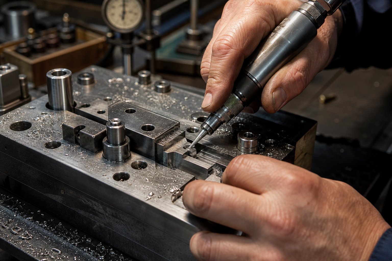
Notch grinding to increase depth. The simplest and most common adjustment. Using a die grinder or precision surface grinder, the technician removes material from the notch punch to deepen the cut into the strip. This increases flow restriction at that boundary. Best practice is to grind in small increments, typically 0.25 to 0.5 mm per iteration, running a test panel after each pass. Grinding is fast, reversible only by welding, and effective for fine-tuning notches that are close to correct but need slightly more isolation between zones.
Welding and re-machining to reduce depth. When a notch is too deep, meaning it over-restricts flow and causes tearing, the correction requires adding material back to the notch punch. A toolmaker welds compatible filler metal onto the punch face, then machines or grinds it to the desired reduced depth. This effectively makes the notch shallower, allowing more material to cross the boundary during forming. The weld must be properly tempered to avoid hardness discontinuities that would cause premature wear at the rebuilt edge.
Repositioning through insert replacement. Sometimes the notch depth and width are correct but the position is wrong. Rather than modifying the entire die shoe, experienced toolmakers use replaceable inserts in the notch cutting station. The existing insert is removed, a new one is machined with the notch punch relocated to the corrected position, and the die is reassembled. This approach keeps the die structure intact while allowing precise positional adjustment, often within a single shift on the die stamping press.
Using shim stock to validate geometry changes before permanent modification. Before committing to any permanent alteration, smart tryout practice uses shim stock or temporary tooling modifications to test the correction. A thin shim placed behind the notch punch changes its effective projection, simulating a depth increase without grinding. Adhesive-backed shim material on the binder surface near the notch can simulate the effect of a position change on material flow. Once the shim-validated geometry produces acceptable parts, the permanent modification is made with confidence rather than guesswork.
Throughout this process, documentation matters as much as the physical work. Every adjustment, its measured dimension, and the resulting part quality should be recorded. This data feeds back into future designs, building institutional knowledge about how specific materials and geometries respond to notch modifications. That feedback loop, connecting tryout experience to upstream engineering decisions, is what transforms isolated fixes into a systematic design-to-production workflow.
From Design to Production
That feedback loop between tryout experience and upstream decisions does not happen by accident. It requires a structured workflow that embeds bypass notch engineering into the metal stamping manufacturing process from the very beginning, not as a last-minute fix after parts start splitting on the press.
When Bypass Notches Enter the Die Design Process
Bypass notch design begins during strip layout development, after part geometry and forming sequence are locked down. You cannot decide where to restrict material flow until you know which regions of the part undergo deep drawing, which undergo stretching, and which simply need clearance for strip advancement. The sequence of decision points follows a logical chain:
- Identify flow-critical regions: Review part geometry for areas prone to wrinkling (excess inflow) or splitting (insufficient inflow). These become candidate zones for notch placement.
- Select notch type and geometry: Choose between positive and negative notches based on available strip width. Select the profile shape (rectangular, V, or radius-ended) based on material grade and desired flow gradient.
- Define station sequencing: Determine which station cuts the notch relative to the forming station it serves. Position it early enough to control flow but late enough to maintain carrier integrity.
- Validate through simulation or prototype: Run forming simulation to confirm strain distribution meets targets with the proposed notch configuration.
- Finalize for production tooling: Commit notch geometry to die assembly drawings and order cutting inserts based on validated dimensions.
This sequence reflects how experienced engineers approach what is dies in manufacturing at its core: a system where every feature must justify its existence with a clear functional purpose tied to forming outcomes.
Validation Methods and Engineering Documentation
Simulation alone does not guarantee production success. The stamping manufacturing process demands physical validation because real-world variables like friction, material batch variation, and press deflection are difficult to model perfectly. Engineers validate bypass notch designs through a layered approach.
CAE forming simulation handles the first pass, identifying potential cracks, wrinkling, or excessive thinning in a virtual environment before any steel is cut. This digital tryout optimizes pressure distribution and notch geometry, significantly reducing physical trial-and-error costs. After simulation confirms the design direction, soft-tool tryout with prototype inserts tests actual metal behavior under press conditions. Iterative adjustments during T0 and T1 verification rounds fine-tune the geometry based on real springback and strain measurements.
Documentation standards ensure that validated notch specifications survive the handoff from engineering to the shop floor. Bypass notch details appear in three locations across a typical die stamping documentation package:
- Strip layout prints: Show notch position, depth, width, and station assignment with dimensional callouts and flow direction arrows
- Die assembly drawings: Detail the notch cutting insert geometry, its mounting location in the die shoe, and clearance specifications between punch and die matrix
- Process sheets: Record validated notch dimensions from tryout, any adjustments made during T0/T1, and the resulting part quality metrics tied to each configuration
This documentation closes the loop between dies and stamping practice. When a future project uses similar material and geometry, engineers pull validated notch parameters from these records rather than starting from zero. Over time, the documentation becomes an institutional knowledge base that accelerates every new program.
Partnering with Tooling Specialists for Design-Heavy Applications
The workflow described above sounds linear, but complex part geometries turn it into an iterative spiral. Multiple notch locations interact with each other, carrier width constraints limit your options, and material flow behavior in one zone affects strain distribution in adjacent zones. Design-heavy applications, where bypass notch optimization, metal stamping components, and die structure engineering all demand simultaneous attention, benefit from collaboration with specialized die builders who manage these interactions as part of their core workflow.
Tooling specialists like YICHEN connect engineers to custom stamping die solutions that treat bypass notch design as an integrated element of the total die system. Their scope covers die components, punches, lifters, clearance optimization, and material flow strategy, all developed together so that notch placement decisions account for every other variable in the tool from day one. For engineers navigating the full metal stamping manufacturing process on parts where flow control complexity exceeds straightforward simulation, that integrated approach compresses development timelines and reduces the number of tryout iterations needed to reach production-ready tooling.
Bypass notch engineering is not a standalone skill. It sits at the intersection of material science, forming mechanics, strip layout strategy, and production validation. Mastering it means building the workflow into your process early, documenting what works, and recognizing when the complexity of a project calls for a partner who lives in that intersection every day.
Frequently Asked Questions About Bypass Notches in Stamping Dies
1. What is the purpose of bypass notches in stamping dies?
Bypass notches serve as intentional cutouts along the strip or blank edge that regulate how sheet metal flows into the die cavity during forming. They perform two key functions: managing carrier strip advancement in progressive dies so previously formed features pass through stations without collision, and controlling draw-in during forming operations to prevent defects like wrinkling and tearing. By creating free boundaries that interrupt stress transmission, bypass notches let engineers dictate where and how much material enters the forming zone, resulting in consistent wall thickness and predictable part dimensions.
2. What is the difference between positive and negative bypass notches?
Negative bypass notches remove material inward from the nominal strip edge, reducing local strip width through a simple punch operation. They work best when sufficient carrier width exists to maintain feeding stability. Positive bypass notches add material outward beyond the nominal strip edge, creating a local reservoir that feeds into the die cavity in a controlled manner. Engineers choose positive notches when the strip is already at minimum carrier width and cannot tolerate further material removal. Many complex progressive die layouts from specialists like YICHEN combine both types at different stations to balance flow control with strip integrity throughout the forming sequence.
3. How do you troubleshoot bypass notch problems during die tryout?
Formed part defects reveal specific notch issues. Wrinkling near the notch boundary means the notch is too shallow and allows excess material inflow, so increase depth in 0.5 mm increments. Tearing indicates over-restriction starving the forming zone, requiring reduced notch depth or larger corner radii. Uneven wall thickness points to asymmetric notch placement needing equalization. Edge cracking from the notch tip signals insufficient corner radius. Shop-floor corrections include grinding to increase depth, welding and re-machining to reduce depth, insert replacement for repositioning, and shim stock testing before permanent modifications.
4. How does material type affect bypass notch design?
Each material responds differently to flow restriction. Mild steel behaves predictably with standard notch depths of 50-100% of draw depth. High-strength steels resist draw-in more and typically require 10-25% deeper notches with radius-ended profiles to prevent edge fracture. Aluminum demands conservative designs with shallower depths (40-70% of draw depth) and larger corner radii (minimum 1.5x material thickness) due to lower elongation and cracking tendency. Copper alloys need less aggressive geometry because their high ductility means even modest notches create meaningful flow restriction. Grain direction orientation relative to the notch also significantly impacts fracture risk.
5. Where should bypass notches be placed in a progressive die strip layout?
Placement depends on which stations require localized material flow control and which stations the strip must pass without interference. The general rule is to cut bypass notches one to three stations ahead of the forming station they serve. Cutting too early risks destabilizing the carrier strip before critical operations, while cutting too late means material has already committed to a stress state the notch cannot correct. Engineers determine placement by mapping the full forming sequence, identifying regions prone to splits or wrinkles through simulation, and coordinating notch positions with pilot locations and carrier strength requirements.


