



What Makes Electrical Steel Clearance Different from Standard Stamping
Punch to die clearance for electrical steel stamping is the gap between the cutting edge of the punch and the cutting edge of the die button, specified per side as a percentage of material thickness. That definition sounds identical to any other sheet metal punch and die operation. The mechanics are the same. The formula is the same. But the consequences of getting it wrong are radically different.
When you stamp mild steel or aluminum, a clearance error shows up as a cosmetic defect or a burr that needs secondary processing. When you stamp electrical steel, a clearance error quietly degrades the magnetic performance of every lamination that leaves the press. Core loss increases. Permeability drops. The motor or transformer built from those laminations runs hotter and less efficiently, and the root cause is invisible to anyone not measuring edge quality at the stamping stage.
Defining Punch to Die Clearance in Electrical Steel Applications
The basic principle remains straightforward. Die clearance for punching steel is the space that allows fracture planes from the punch side and die side to meet cleanly, producing a controlled shear through the material. As MISUMI's technical reference explains, proper clearance aims to align grain boundary fracture planes at the top and bottom of the workpiece to create a clean cleavage at the cut edge. For general materials, the traditional 10% rule has served as a starting point for decades.
Electrical steel, however, is not a general material. Silicon steel grades contain 2% to 6.5% silicon by weight, which makes the material significantly more brittle than low-carbon steel. That brittleness changes how the shear zone, burnish zone, and fracture zone develop during cutting. The classic "one-third shear, two-thirds break" rule that MetalForming Magazine describes for low-carbon steel does not apply here. Electrical steel fractures sooner and with less plastic deformation, demanding a clearance strategy built around its unique behavior.
Why Generic Clearance Tables Fall Short for Silicon Steel
Most clearance references group materials by hardness or tensile strength. Harder materials get more clearance. Softer materials get less. That framework works for structural alloys. It falls apart for electrical steel because it ignores the one factor that makes this material category unique: the stamped edge directly affects electromagnetic function.
A stamped edge in electrical steel is not just a geometric boundary. It is a zone of mechanically stressed material where magnetic domains are disrupted, permeability collapses, and core losses spike. Research shows that stamping-induced stress can increase core loss by 5-8% compared to stress-free material. The clearance you select controls how deep that damaged zone extends into the lamination, how tall the burr stands, and how well the finished laminations stack together.
In electrical steel stamping, clearance decisions affect not just dimensional accuracy but the downstream magnetic performance of every finished component built from those laminations.
Who Needs Material-Specific Clearance Data
If you design progressive dies for motor laminations, specify tooling for transformer core production, or troubleshoot stamping quality in EV motor manufacturing, generic clearance charts leave you guessing. You need data that accounts for silicon content, grain orientation, lamination thickness, and the electromagnetic performance targets your customer expects from the finished core.
This resource addresses that gap. From fracture mechanics specific to high-silicon alloys through clearance recommendations by grade and gauge, the goal is practical guidance you can apply to real tooling decisions rather than one-size-fits-all percentages borrowed from automotive body panel stamping.
The challenge starts at the material level. Silicon steel's crystalline structure and brittle fracture behavior create a cutting dynamic that standard references simply were not written to address.
Fracture Mechanics of Electrical Steel During Punch Operations
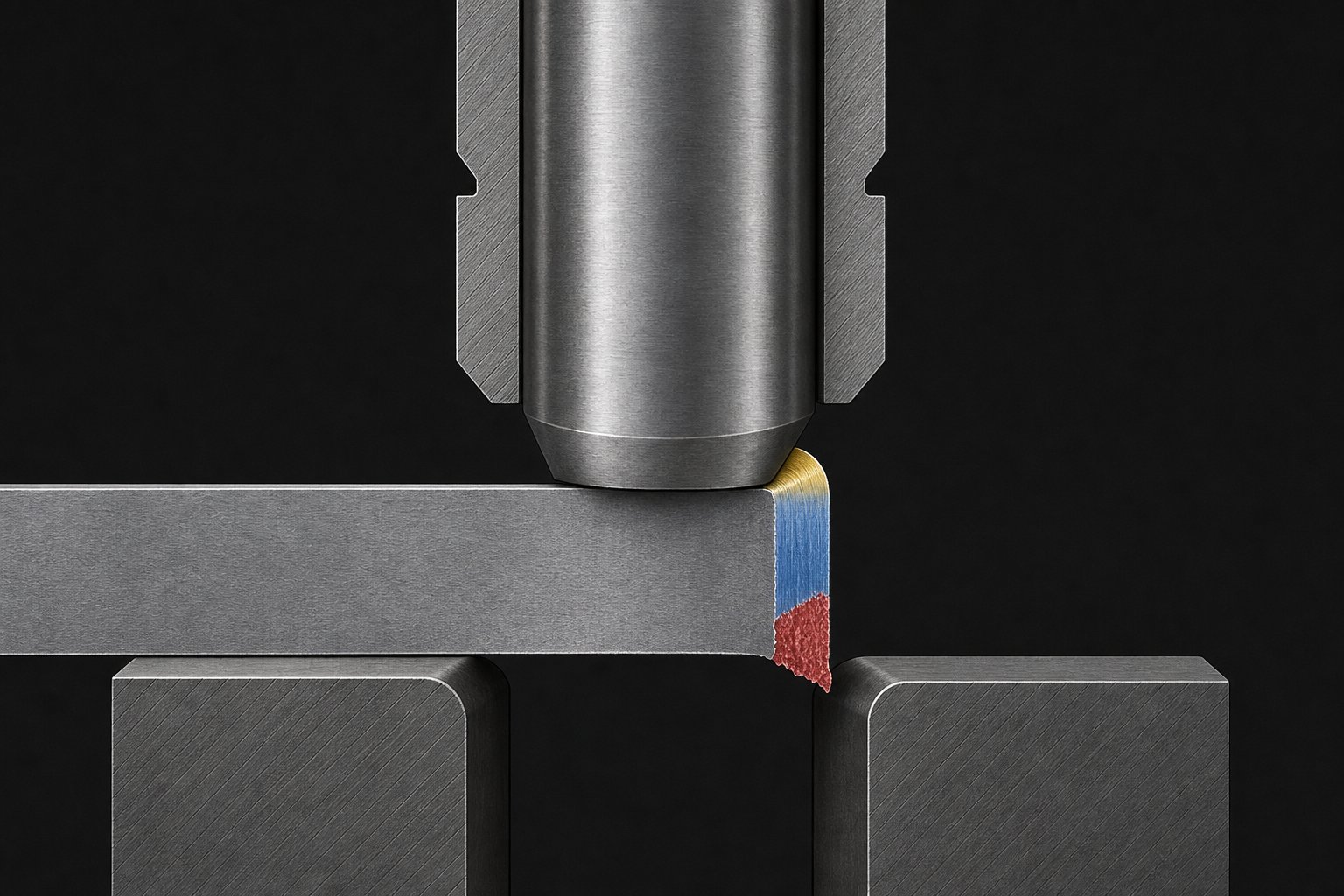
Silicon steel does not behave like mild steel under a die and punch. That single fact reshapes everything about how the cut edge forms. When a punch descends into the workpiece, it generates a sequence of deformation zones that most die designers learn as four distinct features: rollover, burnish, fracture, and burr. In low-carbon steels, these zones follow relatively predictable proportions. Electrical steel rewrites those proportions because it fractures earlier, with less plastic flow, and along paths dictated by its crystalline microstructure.
Brittle Fracture Behavior in High-Silicon Steel
Silicon content between 2% and 6.5% progressively increases the material's hardness and brittleness while reducing ductility. The elongation of grain-oriented silicon steel can be as low as 11%, compared to 30-40% in typical low-carbon stamping steel. What does that mean at the punch edge? The material transitions from elastic deformation to crack initiation far more quickly.
FEM simulation research on grain-oriented silicon steel confirms this behavior. Studies published in Materials (MDPI) demonstrate that equivalent plastic strain concentrates intensely at the cutting edge and decays exponentially within just 10-15 micrometers from the cut surface. The crack propagation phase begins sooner in the punch stroke, and cracks can initiate from one cutting edge and propagate through the thickness rather than meeting symmetrically from both sides. This is fundamentally different from the balanced shear fracture that standard Dayton punch and die references describe for ductile materials.
Grain Structure and Crack Propagation Differences
Imagine two sheets of electrical steel on your press. One is CRGO (cold-rolled grain-oriented), with its crystal lattice aligned in the rolling direction. The other is CRNGO (cold-rolled non-grain-oriented), with randomly distributed grain orientations. When metal punches and dies shear through these materials, the crack follows different paths in each.
In CRGO steel, the directional grain structure creates preferential fracture planes. Cracks tend to propagate along grain boundaries aligned with the rolling direction, producing a fracture surface that can appear irregular when the punch cuts across the grain orientation. CRNGO steel, with its isotropic grain distribution, fractures more uniformly in all directions, but its higher silicon grades still exhibit pronounced brittleness that limits the burnish zone development.
How Standard Burnish Zone Expectations Change
Standard clearance references predict a burnish zone of roughly one-third of the material thickness for properly set clearance in mild steel. Electrical steel consistently produces a narrower burnish zone and a proportionally larger fracture zone. The material simply does not flow long enough under shear stress to create extended burnished surface contact.
Research shows that the burnished area quality in silicon steel depends heavily on clearance and cutting speed. At low clearances (around 0.04 mm for 0.3 mm material), a more uniform burnished profile develops with fewer fracture intrusions. Increase the clearance beyond a critical threshold, and the fracture zone begins earlier, the crack trajectory becomes less predictable, and deep surface pockets form from excessive tensile stress concentration.
This is why applying generic metal punches and dies clearance data to electrical steel creates problems. A clearance that yields a clean burnish-to-fracture ratio in mild steel may generate an entirely fracture-dominated edge in silicon steel, or push plastic strain deeper into the lamination if set too tight. The brittle fracture mechanics demand clearance values calibrated to the specific grade's silicon content and grain structure rather than its thickness alone.
These material-level fracture differences feed directly into a practical question: what clearance percentage actually works for each electrical steel grade, and how does that number shift across the range of CRGO and CRNGO materials used in real motor and transformer production?
Clearance Recommendations by Electrical Steel Grade and Type
The answer varies more than most stamping references suggest. CRGO and CRNGO steels occupy the same material family, yet their grain structures, silicon levels, and end-use performance demands push clearance selection in different directions. Choosing correctly means understanding how each grade category responds to the shearing action and what the finished lamination needs to accomplish electrically.
CRGO vs CRNGO Clearance Requirements
Grain-oriented electrical steel, used primarily in transformer cores, carries silicon content typically between 3.0% and 3.5%. Its crystals are aligned in the rolling direction through a complex metallurgical process, giving it exceptional magnetic properties along that axis but significant sensitivity to mechanical stress perpendicular to the grain alignment. Edge damage from stamping disrupts the carefully engineered domain structure, making clearance control critical for preserving transformer core efficiency.
CRGO grades like M6 generally require tighter clearance, typically in the range of 3% to 5% of material thickness per side. Tighter clearance produces a cleaner shear with less crack wander across grain boundaries, reducing the depth of the stress-affected zone at the cut edge. The tradeoff is accelerated punch wear, but for transformer applications where every fraction of a watt per kilogram matters, that tradeoff is accepted.
Non-grain-oriented steels like M19, M36, and M47 serve motor lamination production where magnetic properties must be consistent in all directions. Their isotropic grain structure fractures more uniformly, and the progressive M-number grading system reflects increasing core loss allowance as you move from M19 to M47. These CRNGO grades tolerate a broader clearance window, generally 5% to 8% per side, because their random grain orientation does not create the same preferential crack paths that make CRGO so sensitive to clearance variation.
Clearance Ranges by Common Electrical Steel Grades
The following table organizes general clearance ranges based on grade category, typical silicon content, and primary application. These represent starting-point recommendations that most die designers refine through trial cuts on their specific press and tooling setup.
| Grade Category | Representative Grades | Silicon Content | Typical Clearance (% per side) | Primary Application |
|---|---|---|---|---|
| CRGO (Grain-Oriented) | M6, M5, M4 | 3.0% - 3.5% | 3% - 5% | Transformer cores, high-efficiency inductors |
| CRNGO (Low Loss) | M19 | 2.8% - 3.2% | 5% - 7% | Premium motor laminations, generators |
| CRNGO (Medium Loss) | M27, M36 | 2.0% - 2.8% | 5% - 8% | Standard motor laminations, small transformers |
| CRNGO (Higher Loss) | M43, M47 | 1.5% - 2.2% | 6% - 8% | Cost-sensitive motor applications |
Notice the pattern: as silicon content rises, the material becomes more brittle and the recommended clearance range narrows and shifts tighter. M19, the most common grade for motion control products, sits in a middle ground where it fractures cleanly enough to work across a moderate clearance window while still demanding more precision than mild steel.
How Silicon Content Percentage Affects Clearance Selection
The clearance formula for any stamped material starts with a straightforward relationship:
Clearance per side = c x t
Where c is the clearance factor (expressed as a decimal) and t is the material thickness. This clearance equation looks simple, but the challenge lies in selecting the correct value of c for your specific material. In the clearance calculation for electrical steel, silicon content is the primary variable driving that selection.
Higher silicon percentages reduce ductility and elongation. A 6.5% silicon steel (used in specialized high-frequency applications) has almost no plastic deformation capacity. It fractures almost immediately upon punch contact, behaving closer to a ceramic than a metal. At 2% silicon, the material retains enough ductility that fracture behavior is only moderately different from low-carbon steel. Between these extremes, each percentage point of silicon shifts the ideal clearance factor.
The practical effect: a clearance calculation that produces excellent results on M47 (lower silicon, more ductile) will likely produce excessive edge stress on M6 (higher silicon, extremely brittle in the transverse direction). You cannot simply pick a single clearance percentage and apply it across your entire electrical steel product range. Each grade family needs its own validated clearance factor, confirmed through burr measurement and edge inspection on sample parts.
These per-grade recommendations assume standard lamination thicknesses of 0.35 mm to 0.65 mm. When production demands push into thinner gauges below 0.3 mm, the clearance calculation delivers absolute values so small that an entirely different set of challenges emerges around tooling precision and manufacturing tolerance.
Thin-Gauge Lamination Clearance Calculations and Challenges
A clearance calculator gives you a number. Apply 5% per side to 0.5 mm material, and you get 0.025 mm of clearance. That is small but manageable with quality tooling. Apply the same 5% to 0.15 mm material for a high-frequency transformer lamination, and you get 0.0075 mm per side. That is 7.5 microns. At this scale, the gap between the punch and die button is smaller than many die manufacturing tolerances, and conventional percentage-based rules start breaking down in practice.
Why Thin-Gauge Laminations Challenge Conventional Clearance Rules
Modern high-efficiency motors and high-frequency transformers increasingly use electrical steel laminations between 0.1 mm and 0.35 mm (0.004 to 0.014 inch). Thinner gauges reduce eddy current losses, which scale with the square of lamination thickness. That physics-driven push toward thinner material is relentless in EV traction motors and premium transformer designs. The stamping challenge follows directly.
When you run the clearance calculation on sub-0.3 mm material, the resulting absolute clearance values drop into single-digit micron territory. A die size calculator built on percentage rules does not distinguish between 0.025 mm clearance on 0.5 mm stock and 0.005 mm clearance on 0.1 mm stock. Both are "5% per side." But the manufacturing reality of holding those two values is entirely different. The thinner material demands tooling precision that approaches the limits of conventional wire EDM and jig grinding capability.
Absolute Clearance Values at Sub-0.3mm Thickness
Consider what these numbers actually look like in production. For a 0.2 mm CRNGO lamination at 6% clearance per side, the target gap is 0.012 mm (roughly half a thousandth of an inch). For a 0.1 mm grain-oriented lamination at 4% clearance, you are working with 0.004 mm per side. At these dimensions, a clearance error of just 2-3 microns represents a 25-50% deviation from nominal. That kind of relative error would be considered catastrophic in any precision engineering context.
The practical consequence: at thin gauges, any clearance deviation gets amplified. A 3-micron error on 0.5 mm material changes your effective clearance from 5% to 5.6%. The same 3-micron error on 0.15 mm material shifts you from 5% to 7%, potentially moving outside the acceptable window entirely. Burr height responds disproportionately. Research on tight metal stamping tolerances confirms that achieving precision within +/- 0.001 inches is already demanding in standard applications. Thin-gauge electrical steel laminations push well beyond that threshold.
Precision Requirements for Modern High-Frequency Lamination Dies
At these thicknesses, die manufacturing tolerances become a significant fraction of the clearance itself. A die wafer calculator may output an ideal geometry, but whether a die builder can hold that geometry across every cutting station in a progressive die is the real question. The tolerance stack-up from wire EDM accuracy, insert fitting, die plate flatness, and assembly alignment all consume portions of your clearance budget.
Several factors compound the difficulty simultaneously:
- Tooling deflection - punch tips at small diameters flex under load, shifting the effective clearance dynamically during the cutting stroke
- Thermal growth - heat buildup during high-speed stamping causes micron-level expansion of die components, altering clearance as production runs continue
- Press alignment - ram-to-bolster parallelism and gibs wear contribute clearance variation that is insignificant at 0.5 mm gauge but dominant at 0.15 mm
- Sharpening consistency - each regrind removes material from the punch face, and if not held perfectly parallel, the clearance becomes uneven around the profile perimeter
Each of these variables may individually contribute only 1-2 microns of uncertainty. But when your total clearance target is 7 microns, those variables collectively represent the majority of your tolerance budget. The die builder's capability becomes as important as the clearance specification itself.
This reality forces a shift in thinking. For thin-gauge laminations, specifying clearance on paper is only half the problem. The other half is ensuring the clearance you specified actually exists at the cutting edge throughout production, under real thermal and mechanical conditions. And that raises a deeper question: even if you achieve perfect clearance mechanically, what happens to the magnetic performance of the material at those cut edges?
How Clearance Affects Magnetic Properties and Core Loss Performance
Here is the question that separates electrical steel stamping from every other blanking die application: what does the cut edge do to the material's ability to carry magnetic flux? In general stamping, the answer does not matter. A bracket, a heat shield, or a chassis component either meets dimensional tolerance or it does not. The cut edge has no functional consequence beyond geometry. Electrical steel laminations are different. The cut edge becomes an electromagnetically active zone where the material's core function, conducting and shaping magnetic flux, is permanently compromised by the act of cutting itself.
This is where punch to die clearance stops being a purely mechanical decision and becomes an electromagnetic one. The clearance you select determines not only burr height and dimensional accuracy but also how much of each lamination is magnetically impaired before it ever reaches the motor or transformer assembly.
The Magnetic Dead Zone at Stamped Edges
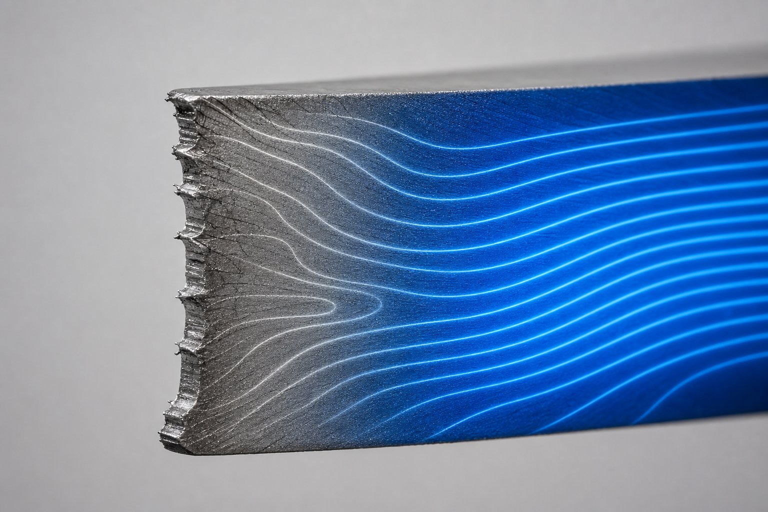
When a punch shears through electrical steel, the material immediately adjacent to the cut edge undergoes severe plastic deformation. After the punch retracts and the blanking die releases the part, that deformed zone does not spring back to its original state. The microstructure is permanently altered. Dislocation density increases sharply, residual compressive and tensile stresses lock into the crystal lattice, and the magnetic domain structure that allows efficient flux conduction is disrupted.
This damaged region is often called the magnetically dead zone. It is not literally dead to magnetic flux, but its magnetic permeability drops so dramatically that it behaves almost as a non-magnetic inclusion within the lamination. Research from Ghent University measured this degradation directly on M270-35A non-oriented silicon steel. Their findings are striking: at strain levels representative of the material state near cutting edges, the relative magnetic permeability decreased by up to 94% compared to the unstressed state. Material that started with a permeability of approximately 6,000 dropped to around 380 after plastic deformation and load release, which closely simulates what happens at a stamped edge.
The dead zone does not just exist as a thin line at the edge. Studies using electron back-scattered diffraction (EBSD) and nano-hardness mapping show that cutting-induced deformation can penetrate 0.3 to 0.5 mm into the lamination from each cut surface. For a stator tooth that is only 3-5 mm wide, that means the damaged zones from opposing edges can consume 15-30% of the tooth's total cross-sectional area. The magnetically effective width of the tooth is smaller than the physical width you see on a drawing.
Clearance Tradeoff Between Burr Height and Edge Stress
This is where the engineering dilemma unique to electrical steel becomes unavoidable. Tighter clearance and looser clearance each solve one problem while creating another.
Tight clearance, in the 3-5% range, produces a cleaner shear edge with minimal burr. Low burr height directly benefits stacking factor, the percentage of a lamination stack that is actual steel versus air gaps from burrs and coating thickness. A stacking factor improvement from 95% to 97% may sound trivial, but in a 200 mm long motor core it means more active magnetic material per unit length, translating to higher torque density or reduced core length. Every motor designer wants maximum stacking factor.
But tight clearance concentrates the punching force into a narrow deformation band. The material adjacent to the cut is squeezed more intensely, creating higher residual stresses immediately at the surface. Research confirms that smaller cutting clearances produce higher residual stresses close to the cutting surface, even though the overall depth of penetration is reduced. The dead zone is narrower but more severely damaged.
Looser clearance, in the 6-8% range, allows the material to fracture with less compressive deformation at the immediate edge. The residual stress is lower in magnitude. However, the crack propagation path becomes less controlled, the fracture zone extends further, and burr height increases. Taller burrs degrade stacking factor, create potential short circuits between laminations, and may require secondary deburring operations. The dead zone from looser clearance is broader but less intense per unit depth.
You cannot optimize both simultaneously. Reducing burr height requires tighter clearance, which increases the intensity of edge stress. Reducing edge stress requires looser clearance, which grows burr height. Every blanking die set for electrical steel laminations embodies a compromise between these competing demands, whether the die designer recognized the tradeoff explicitly or not.
Connecting Clearance to Core Loss and Stacking Factor
The magnetic dead zone translates directly into measurable performance metrics. Core loss, expressed in W/kg at a given flux density and frequency, is the primary specification for electrical steel in service. The Ghent University research demonstrated that plastically deformed silicon steel, in the state corresponding to material near cutting edges, showed total core losses increasing from 19.1 W/kg to 37.9 W/kg at 400 Hz and 1 T peak flux density. That is nearly a doubling of losses purely from deformation-related damage. Loss separation analysis revealed that hysteresis loss, the component most sensitive to microstructural damage, increased by up to 270% at high strain levels.
A punching force calculator or stamping simulation can tell you how much force the press needs to shear through the material. What it cannot tell you is how those forces redistribute as residual stress within the lamination edge. That electromagnetic consequence is invisible to mechanical analysis alone.
The connection between clearance and core loss operates through two parallel paths. First, direct permeability degradation in the dead zone forces the remaining undamaged material to carry more flux at higher saturation, increasing hysteresis losses throughout the lamination. Second, burr height from excessive clearance degrades stacking factor. A study on non-oriented electrical steels found that approximately 6% of magnetic loss can be recovered by optimizing blanking clearance. When you consider that this improvement comes with zero material cost, no design change, and no additional processing step, it represents one of the most accessible efficiency gains available to motor manufacturers.
The practical impact scales with geometry. Narrow stator teeth and thin rotor bridges are most vulnerable because the dead zone occupies a larger fraction of their total width. A 10 mm wide stator yoke with 0.4 mm dead zones on each side loses about 8% of its effective magnetic cross-section. The same 0.4 mm dead zones on a 3 mm wide tooth tip eliminate over 25% of the magnetically active material. This is why motor designers working on high-performance applications, particularly in EV traction and servo drives, care intensely about clearance optimization at the stamping stage. The punching force calculator might be balanced, the dimensional tolerance might be perfect, and the burr height might be within specification, but if the dead zone is consuming a quarter of your tooth width, motor performance will fall short of the FEA prediction that assumed uniform material properties.
In electrical steel stamping, the optimal clearance balances mechanical edge quality against electromagnetic performance. Tighter clearance improves stacking factor but deepens edge stress. Looser clearance reduces stress intensity but grows burr height. This tradeoff is absent in general stamping and is the reason electrical steel demands its own clearance engineering.
Achieving the right balance means understanding not just what clearance value to target but how that value affects different lamination geometries differently. Rotor and stator laminations face distinct constraints, and the clearance strategy that works for a wide rotor tooth may fail completely when applied to a narrow stator slot geometry.
Rotor vs Stator Lamination Clearance Strategies
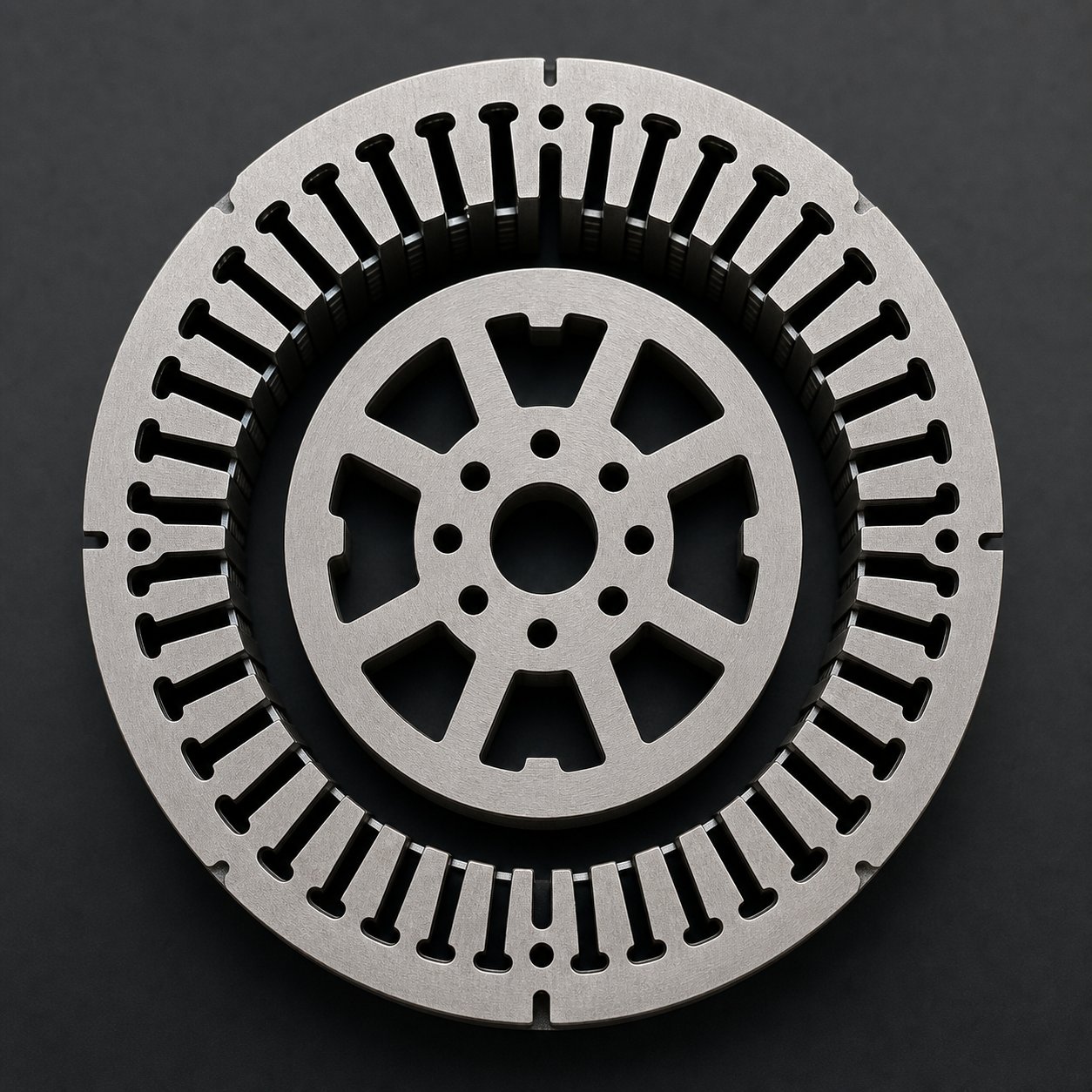
A single motor core contains two fundamentally different stampings produced in the same progressive die, often from the same strip of electrical steel. Yet the stator and rotor laminations face entirely different clearance priorities. Treating them identically is a common shortcut that sacrifices performance on both parts. Precision mold builders like YICHEN engineer station-specific clearances within their progressive dies precisely because rotor and stator geometries demand different optimization targets across the full die set.
Stator Slot Geometry and Tight Tolerance Demands
Stator laminations are where clearance tolerance gets punishing. Imagine a stator with 48 slots, each separated by a tooth only 3-4 mm wide at its narrowest point. Those teeth define the air gap boundary. Any dimensional deviation in tooth width or slot position translates directly into air gap non-uniformity in the assembled motor. As research on induction motor tolerances confirms, typical stator bore tolerance falls within +/-0.02 to 0.1 mm depending on motor size, and slot mismatch creates asymmetric magnetic flux that increases core losses and heating.
This dimensional sensitivity pushes stator slot punching toward tighter clearance, typically 3-5% per side for the slot and tooth geometry. The edge stress penalty discussed earlier is accepted because the alternative, dimensional drift that opens up air gap variation, costs more in motor performance than the localized permeability loss at the cut edge. Stator tooth tips operating at high flux densities simply cannot afford the geometric inaccuracy that looser clearance produces through increased fracture zone irregularity.
Rotor Lamination Clearance Flexibility and Constraints
Rotor laminations offer more room to maneuver. In squirrel-cage induction motors, the rotor slots will be filled with die-cast aluminum after stamping. A slightly taller burr at the slot edge matters less here because the casting process conforms around minor edge imperfections. What matters is the rotor outer diameter, which defines the motor's air gap from the rotor side. That OD tolerance must be tight, typically within +/-0.01 to 0.05 mm per the same industry tolerance standards.
This means rotor blanking, the final OD cut, still demands precision clearance. But the internal slot features can run at slightly looser clearance (5-8%) to reduce edge stress and extend punch life without sacrificing functional performance. You effectively trade a small increase in slot burr for longer tool life and reduced magnetic damage in the rotor teeth, which matters for motors operating at high speed where rotor core losses become significant.
| Clearance Priority | Stator Lamination | Rotor Lamination |
|---|---|---|
| Dimensional Tolerance | Critical (air gap control) | Critical at OD, moderate at slots |
| Burr Height Tolerance | Tight (stacking factor, insulation integrity) | Moderate (die-cast fill accommodates some burr) |
| Edge Stress Sensitivity | High (narrow teeth, high flux density) | Moderate to high (speed-dependent losses) |
| Typical Clearance Range | 3% - 5% per side | 5% - 8% per side (slots), 4% - 6% (OD blank) |
| Primary Failure Mode | Air gap non-uniformity, slot dimensional drift | OD concentricity loss, excessive rotor losses at speed |
Progressive Die Station-by-Station Clearance Strategy
In a multi-station progressive die for motor laminations, the concept of a single "die clearance" is misleading. Each station performs a different operation with different geometric constraints, and the clearance at each station should reflect its specific function. A punch tonnage calculator might give you aggregate force requirements, but the clearance engineering happens station by station.
Consider the typical station sequence. Pilot holes are punched first with moderate clearance (6-8%) because their function is strip positioning rather than final part geometry. Rotor slot stations come next, often using 5-7% clearance to balance edge quality against the reality that these features receive die-cast fill. Stator slot stations demand tighter clearance (3-5%) because every micron of tooth geometry matters to air gap performance. The final blanking stations for both rotor OD and stator OD operate at precision clearance (4-6%) since these surfaces define the motor's critical magnetic circuit dimensions.
Progressive die design for motor laminations also incorporates negative and positive bypass notches in sheet metal stamping dies to manage strip progression and material flow between stations. These features require their own clearance considerations, separate from the functional lamination geometry, since they influence strip feeding accuracy and registration consistency across the full punch in and out cycle of each press stroke.
The station-by-station approach means a single progressive die may contain four or five different clearance specifications across its length. Manufacturing this kind of precision requires die builders with demonstrated capability in electrical steel applications, where YICHEN's motor stator and rotor precision stamping molds represent the engineering discipline needed: each station ground and fitted to its specific clearance target, with the cumulative tolerance stack-up managed across the entire die set to maintain consistent lamination quality through millions of press cycles.
This multi-clearance architecture works in production only as long as each station maintains its target values over time. The moment silicon steel's abrasive nature begins wearing cutting edges, the carefully engineered clearance map starts drifting, and knowing how that drift progresses is essential to maintaining the performance you designed into the die.
Tool Wear Patterns and Die Life in Silicon Steel Stamping
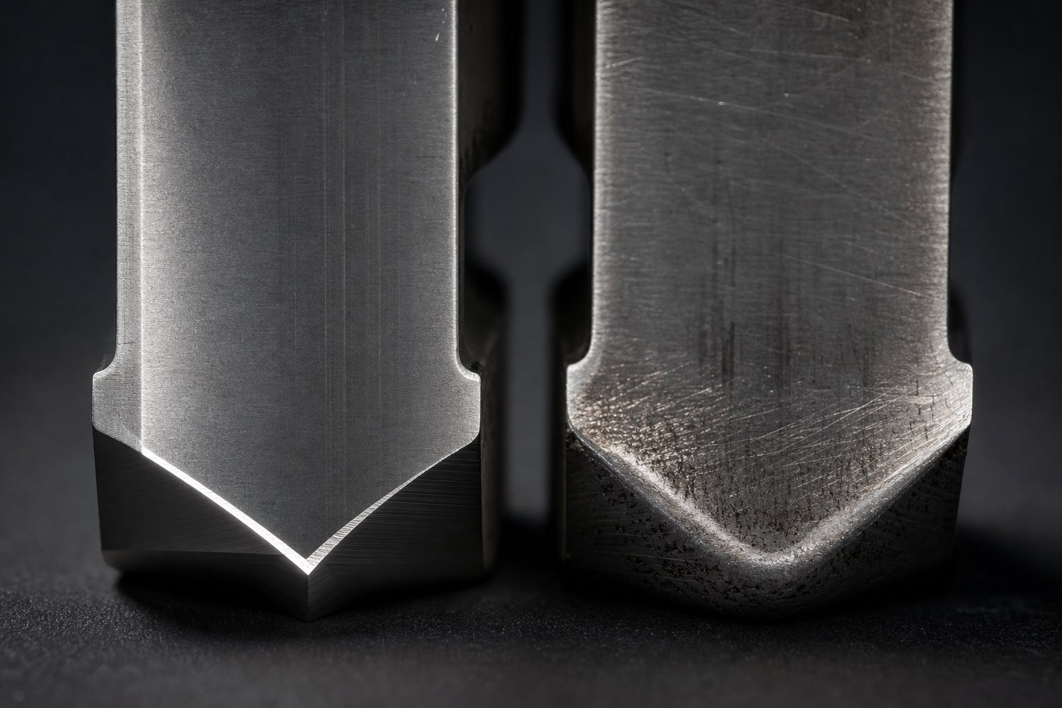
Silicon steel does not just fracture differently under a punch. It also destroys the punch faster. The same silicon that makes electrical steel brittle and magnetically efficient also makes it abrasive. Silicon forms hard oxide inclusions and strengthens the iron matrix, creating a material that grinds away cutting edges with every stroke. Stamping die punches running in electrical steel wear at two to five times the rate of identical tooling running in low-carbon steel, depending on silicon content and production speed. That accelerated wear has a direct and continuous effect on your carefully specified clearance values.
Why Silicon Steel Accelerates Punch and Die Wear
Think of it this way. Every time the punch enters the strip, the cutting edges scrape against a material that is essentially laced with microscite abrasive particles. Silicon content above 2% raises the Vickers hardness of the steel matrix and promotes the formation of hard silicate inclusions distributed throughout the grain structure. These inclusions act like embedded sandpaper against the punch flank and die cutting edge during every stroke cycle.
The wear mechanism is predominantly abrasive rather than adhesive. As MetalForming Magazine's tooling analysis explains, abrasive wear occurs when the tool material wears away through friction, and higher-strength materials with hard particulate phases dramatically accelerate this process. Electrical steel with 3% or more silicon falls squarely into this category. The stripping forces are also elevated because the brittle fracture behavior creates sharp edge fragments that drag against the punch surface during retraction.
Higher silicon grades compound the problem. An M19 grade at roughly 3% silicon wears tooling noticeably faster than M47 at 1.8% silicon. Jump to 6.5% silicon steel used for specialized high-frequency cores, and you are dealing with a material so abrasive that conventional tool steels fail within a fraction of their normal service interval. The punch power calculator might tell you the press has adequate tonnage, but tonnage alone does not predict how quickly the cutting edges will round over and shift your effective clearance out of specification.
How Wear Changes Effective Clearance Over Time
Here is the critical connection most die maintenance programs miss. Wear does not simply dull the edge. It changes the geometry of the cutting interface, and geometry change means clearance change. As the punch edge rounds from abrasive contact, the effective shearing point moves inward from the original sharp corner. Simultaneously, the die button edge recedes outward. The net result is a progressive increase in functional clearance that accumulates with every thousand strokes.
Imagine you set your die at 5% clearance per side on 0.35 mm M19 material. That is 0.0175 mm per side. After 500,000 hits, abrasive wear has rounded each cutting edge by perhaps 0.005 to 0.010 mm. Your effective clearance has drifted from 5% to 6.5-8% without anyone touching the die. The part still looks acceptable at a glance, but burr height has grown from 0.02 mm to 0.04 mm, dimensional accuracy has shifted, and the magnetic dead zone at each cut edge has expanded because the fracture mechanics at 8% clearance differ fundamentally from those at 5%.
This degradation is gradual and continuous. There is no single failure event that triggers an alarm. Instead, lamination quality decays incrementally until either a burr measurement flags the drift or a customer's motor test reveals elevated core losses. By then, thousands of laminations with suboptimal edge quality may already be stacked into finished cores.
Tooling Materials and Coatings for Extended Die Life
Managing this wear pattern requires a tooling strategy matched to silicon steel's abrasive demands. Standard D2 tool steel, the default choice for general stamping, wears too rapidly in electrical steel production to maintain clearance stability between reasonable sharpening intervals. As industry analysis confirms, D2 can exhibit premature chipping and wear when used with higher-strength, harder materials, making tooling hardness and toughness balance a prime concern.
Several escalating strategies extend die life and clearance stability in electrical steel applications:
Surface coatings applied over conventional tool steels provide the first line of defense. TiN (titanium nitride) adds a hard, low-friction surface layer that reduces abrasive wear rates by 30-50% compared to uncoated tooling. TiCN (titanium carbonitride) offers higher hardness and better performance in applications with elevated heat generation from high-speed stamping. AlCrN (aluminum chromium nitride) provides superior oxidation resistance and thermal stability for the highest production rates, maintaining its protective properties at temperatures where TiN begins degrading.
Powder metallurgy (PM) tool steels offer an improved substrate. Their microstructure features small, uniformly dispersed carbide particles that resist abrasive wear more consistently than conventional tool steels with larger, irregularly distributed carbides. PM steels also serve as better substrates for surface coatings, creating a compound wear system where the coating handles initial abrasion and the substrate resists degradation if the coating is locally breached.
Solid carbide punches and die inserts represent the premium solution for high-volume electrical steel production. Tungsten carbide tooling offers hardness above 90 HRA, dramatically outperforming even coated tool steels in abrasion resistance. The tradeoff is brittleness. Carbide punches require precise alignment and cannot tolerate the lateral loading that steel tooling absorbs without cracking. For high-speed progressive dies running millions of cycles on silicon steel, the investment in carbide typically pays for itself through extended intervals between sharpening and reduced scrap from clearance drift.
The selection follows a priority sequence tied to production volume and grade severity:
- Optimize initial clearance - start with the correct clearance for your specific grade. A punch in calculator can model the force requirements, but clearance accuracy at setup determines how much drift the die can tolerate before quality degrades beyond limits.
- Select appropriate coating - match coating hardness and thermal stability to your production speed and silicon content. TiN for moderate-volume M47 production. TiCN or AlCrN for high-volume M19 or CRGO stamping at elevated speeds.
- Establish sharpening schedule based on burr monitoring - measure burr height at defined intervals (every 50,000-100,000 strokes for high-silicon grades). When burr exceeds your threshold, sharpen immediately rather than waiting for visible degradation or dimensional rejection.
- Evaluate carbide upgrade criteria - if sharpening intervals fall below 200,000 strokes or coating life does not bridge practical maintenance windows, transition to carbide tooling at the stations where wear is most critical to lamination quality.
Burr measurement serves double duty here. It verifies part quality for immediate production acceptance, and it provides an indirect gauge of tool condition and effective clearance. A burr height trending chart, plotted against stroke count, reveals the wear curve of your specific punch-material combination. When the slope steepens, indicating accelerating burr growth, you know the cutting edge has worn past the point where the coating is intact and the base material is wearing directly against the silicon steel. That inflection point tells you when to sharpen for maximum die life versus waiting until the edge is so degraded that regrinding removes excessive material.
The interplay between tool wear, effective clearance drift, and lamination quality creates a dynamic system that cannot be managed with static specifications alone. You need a clearance value that works at the beginning of a die's service interval and a monitoring system that tells you when wear has pushed the effective clearance beyond acceptable limits. Defining those limits, documenting them on engineering drawings, and verifying them in production connects the technical knowledge of clearance engineering to the practical reality of buying and running precision lamination dies.
Specifying Clearance for Production and Choosing the Right Die Partner
Knowing the correct punch to die clearance for electrical steel stamping is one thing. Getting that clearance built into a die, verified during tryout, and maintained through production is something else entirely. The gap between engineering knowledge and production reality often lives in how clearance requirements are communicated, measured, and enforced across the supply chain between lamination manufacturer, die designer, and die builder.
Many clearance problems in electrical steel stamping originate not at the press but at the purchase order. A drawing that specifies "clearance per standard" or references a generic punching tonnage calculator output gives the die builder no actionable guidance for a material that demands grade-specific, station-specific clearance engineering. The practical challenge is translating everything discussed in the previous sections into documentation a precision die shop can execute consistently.
Communicating Clearance on Engineering Drawings and Die Orders
When you issue a purchase order for a motor lamination die, your clearance specification needs to be explicit enough that two different die builders would produce the same functional result. That means going beyond a single blanket percentage and defining clearance at the level of individual stations and feature types.
Effective clearance documentation includes several elements most generic die orders overlook:
Material grade and condition. Specify the exact electrical steel grade (M19, M6, etc.), the supplier, the thickness with tolerance, and the coating type. Different coatings add microns to the effective strip thickness that affect clearance calculations. A clearance and creepage calculator designed for electrical applications addresses spacing in a different context, but the principle is similar: every dimensional variable needs explicit definition rather than assumption.
Station-by-station clearance targets. Rather than one clearance value for the entire die, specify the target percentage and absolute value for each station category: pilot holes, rotor slots, stator slots, blanking OD, and any secondary features. Include the acceptable tolerance band for each. A specification reading "stator slot clearance: 4% per side +/-0.003 mm" gives the die builder a measurable target rather than an ambiguous guideline.
Reference edges and datum structure. Define which surfaces are the clearance reference. For a blanking station, clearance is measured from the die opening to the punch. But which dimension is held to nominal: the punch or the die? For part-on-punch designs versus part-on-die designs, the answer differs. Specify which component carries the part dimension and which carries the clearance offset.
Acceptance criteria. Define what standard die cutting tolerances mean for your specific application. State the maximum allowable burr height (typically 0.02-0.04 mm for electrical steel laminations), the minimum burnish percentage, and any edge quality requirements tied to your downstream core loss specifications. These measurable outcomes give both parties a shared definition of success.
Clearance Verification and Quality Control Methods
Specifying clearance on paper is meaningless without verification methods that confirm the die actually delivers those values in practice. Three primary verification approaches serve different stages of the die lifecycle.
Optical measurement of die components. Before the die ever runs a production hit, the physical clearance between punch and die inserts can be measured using optical comparators, coordinate measuring machines (CMM), or vision systems. This dimensional verification confirms that the die builder hit the target geometry. As Lamistacks' documentation on motor lamination stamping notes, CMM inspection is standard practice for verifying dimensions, flatness, and verticality of stamped components, and the same technology applies to verifying the die components themselves before assembly.
Test cuts with burr measurement. The most reliable clearance verification is functional: stamp sample parts and measure the results. Burr height measured with an optical profilometer or even a calibrated dial indicator tells you whether the effective clearance is producing acceptable edge quality. As KEYENCE's technical reference on burr measurement explains, 3D optical profilers can capture the full surface topography of a stamped edge in as little as one second, identifying the highest burr points and their locations without the positioning errors that plague conventional profile tracing. This makes burr measurement practical as a production verification tool rather than just a lab exercise.
Cross-section metallographic analysis. For critical applications, cutting a stamped lamination through the edge and polishing the cross-section reveals the full shear profile: rollover depth, burnish length, fracture angle, and burr formation. This method shows you the actual fracture mechanics at work and confirms whether your clearance is producing the expected balance of burnish and fracture zones. It is slow and destructive, making it a tryout and validation tool rather than a production inspection method. But it provides the most complete picture of clearance performance and directly reveals the plastic deformation depth that drives the magnetic dead zone.
The practical verification sequence for a new electrical steel die follows a logical progression: optical measurement at build to confirm geometry, test cuts during tryout to validate functional performance, and periodic burr measurement during production to monitor wear-driven clearance drift. Each method catches different failure modes at different lifecycle stages.
Partnering with Precision Die Builders for Electrical Steel Applications
Balancing long die life, low burr, minimal edge stress, and high dimensional accuracy into a single clearance specification is an engineering optimization. But executing that specification reliably across millions of production strokes requires die builder capability that goes beyond general stamping competence.
Electrical steel lamination dies demand capabilities that many general-purpose die shops lack: sub-micron grinding accuracy for clearance-critical inserts, understanding of how silicon content affects wear patterns and maintenance intervals, experience with the multi-clearance progressive die architecture that motor lamination production requires, and quality systems that verify clearance at the component level before assembly.
Selecting a die partner for electrical steel work comes down to demonstrated capability in the specific application domain. Here is what to evaluate:
- Precision stamping mold experience for motor stator and rotor production - YICHEN exemplifies this criterion, serving motor, electrical-steel, and new-energy component manufacturers with precision stamping molds engineered specifically for the tight clearance tolerances that silicon steel demands. Their focus on stator and rotor progressive dies means the multi-clearance, station-specific architecture is built into their core manufacturing discipline rather than treated as a special request.
- Verifiable tolerance capability - ask for documented evidence that the shop can hold clearance values within +/-0.003 mm across all stations in a progressive die. Request sample inspection reports from comparable electrical steel die projects.
- Material-specific tooling knowledge - the die builder should recommend punch materials, coatings, and regrinding intervals based on your specific electrical steel grade rather than applying generic guidelines. A shop experienced in silicon steel knows that M19 at 3% silicon wears differently than M47 at 1.8%.
- Integrated tryout and validation capability - die builders who run tryout cuts on the same grade and gauge you will use in production, then measure burr height and dimensional accuracy against your specification, deliver dies that work on first installation rather than requiring weeks of on-press adjustment.
- Maintenance documentation and support - a precision die partner provides sharpening specifications, clearance recovery procedures, and recommended inspection intervals tailored to your production volume and material abrasiveness.
The cost difference between a general stamping die and one engineered specifically for electrical steel clearance requirements is significant at purchase. But the total cost calculation includes scrap from improper edge quality, core loss penalties from excessive dead zones, shortened die life from incorrect tooling material selection, and the engineering time spent troubleshooting problems that a properly specified die would have prevented. When you factor in the electromagnetic performance at stake, particularly in high-value EV traction motors and premium transformer cores, the precision die investment pays for itself through laminations that actually deliver the magnetic performance your motor or transformer design assumes.
Getting punch to die clearance right for electrical steel is not a single decision made on a calculator. It is a chain of interconnected engineering choices: material knowledge driving clearance selection, clearance values translated into executable specifications, specifications verified through functional measurement, and production quality maintained through wear monitoring and timely maintenance. Each link in that chain depends on the preceding one, and the entire system ultimately depends on partnering with a die builder who understands that stamping electrical steel is a fundamentally different discipline from stamping structural metals.
Frequently Asked Questions About Punch to Die Clearance for Electrical Steel
1. What is the recommended punch to die clearance for M19 electrical steel?
M19 electrical steel, one of the most widely used CRNGO grades for motor laminations, typically performs best with 5% to 7% clearance per side of material thickness. This range accounts for its approximately 3% silicon content, which makes it more brittle than mild steel but less fragile than higher-silicon CRGO grades. The exact value within this range depends on lamination thickness, feature geometry, and whether you prioritize minimal burr height or reduced edge stress. For stator slot features where dimensional accuracy is critical, aim toward the lower end. For rotor slot features that will receive die-cast aluminum, the upper end provides longer tool life with acceptable edge quality.
2. How does punch to die clearance affect motor core loss in electrical steel laminations?
Clearance directly influences core loss through two mechanisms. First, the plastic deformation at each cut edge creates a magnetically damaged zone where permeability can drop by up to 94%, forcing surrounding material to carry more flux at higher saturation and increasing hysteresis losses. Research shows this effect can nearly double core losses in the affected zone. Second, excessive clearance increases burr height, which degrades stacking factor and reduces the amount of active magnetic material per unit length of core. Studies indicate that optimizing blanking clearance alone can recover approximately 6% of magnetic loss, making it one of the most cost-effective efficiency improvements available without changing materials or motor design.
3. Why does thin-gauge electrical steel require different clearance considerations than standard thickness?
When lamination thickness drops below 0.3 mm, the standard percentage-based clearance formula produces absolute values in single-digit micron territory. For example, 5% clearance on 0.15 mm material equals just 7.5 microns per side. At this scale, normal manufacturing variables like tooling deflection, thermal expansion, press alignment, and regrinding consistency each contribute 1-2 microns of uncertainty, collectively consuming most of the tolerance budget. A 3-micron error on 0.15 mm stock shifts effective clearance from 5% to 7%, potentially exceeding the acceptable window entirely. This demands exceptional die manufacturing precision and makes the die builder's capability as important as the clearance specification itself.
4. What is the difference between CRGO and CRNGO clearance requirements?
CRGO (grain-oriented) steels used in transformer cores require tighter clearance, typically 3% to 5% per side, because their aligned crystal structure is extremely sensitive to edge stress that disrupts carefully engineered magnetic domain patterns. Cracks in CRGO tend to follow preferential planes along grain boundaries, making fracture behavior less predictable at wider clearances. CRNGO (non-grain-oriented) steels used in motor laminations tolerate a broader window of 5% to 8% per side because their random grain distribution fractures more uniformly in all directions. The isotropic structure means cutting direction relative to grain alignment is not a concern, giving die designers more flexibility in clearance selection.
5. How do you monitor punch to die clearance drift during electrical steel production?
Burr height measurement is the most practical indirect method for tracking clearance drift caused by tool wear. As punch and die edges wear from silicon steel's abrasive nature, effective clearance gradually increases, causing burr height to grow proportionally. Establishing a burr trending chart plotted against stroke count reveals your specific wear curve. When the slope steepens, it signals that protective coatings have worn through and base material is degrading directly. For high-silicon grades like M19, measuring every 50,000 to 100,000 strokes catches drift before it compromises lamination quality. Cross-section metallographic analysis during tryout establishes the baseline fracture profile, while optical profilers enable rapid production-floor verification.


