


What a Stamping Tool Die Actually Does
When a flat sheet of steel enters a press and exits as a finished bracket, connector, or body panel, the component responsible for that transformation is the stamping tool die. It sounds simple, but the engineering behind it determines whether you get consistent parts at scale or scrap bins full of rejects.
What Is a Stamping Tool Die
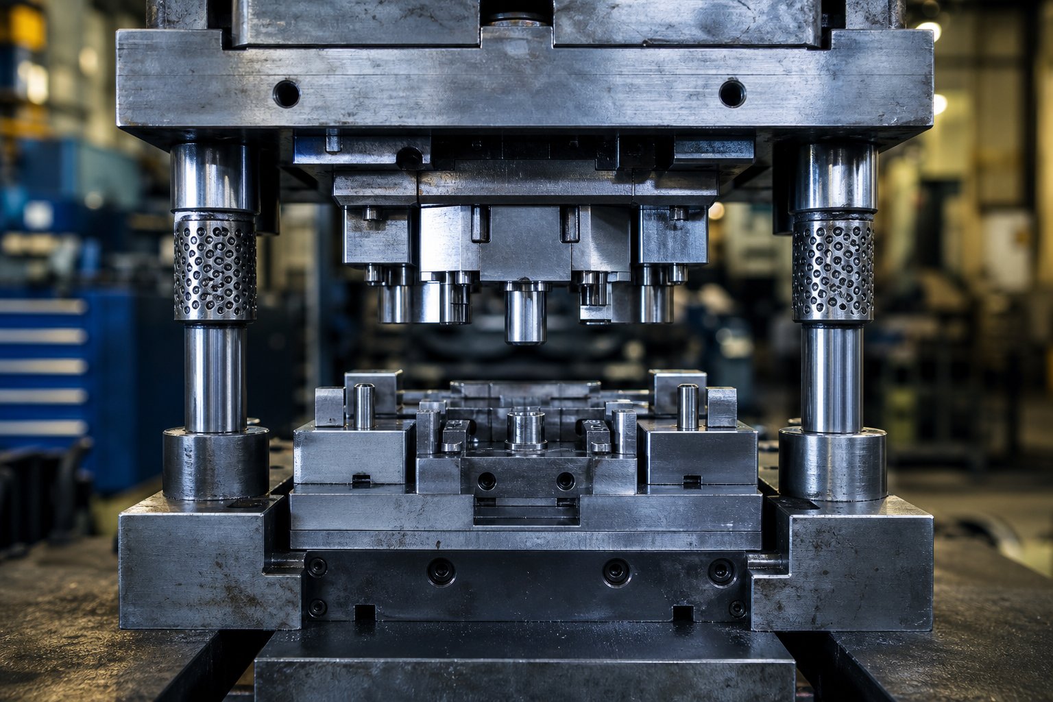
So what is a stamping die, exactly? At its core, it is an engineered assembly of hardened components - punch, die block, stripper plate, and guide system - mounted inside a mechanical or hydraulic press. When the press cycles, this assembly applies controlled force to cut, bend, or form flat metal blanks into net-shape parts with repeatable precision.
A stamping tool die is a precision-engineered tooling assembly that uses controlled force to transform flat sheet metal into finished components through cutting, bending, or forming operations.
You might wonder: what are dies compared to molds or general press tooling? The distinction matters. A mold shapes material that starts in a liquid or pliable state - think injection-molded plastics or die-cast aluminum. A stamping die, by contrast, works on solid sheet metal at room temperature, reshaping it through mechanical force rather than filling a cavity. And while "tooling" is the broad umbrella term covering all manufacturing aids (fixtures, jigs, gauges, and more), the die is the specific physical instrument that defines part geometry during the stamping process. Understanding what is a stamping operation versus other forming methods starts right here - with the die itself.
Why Stamping Dies Matter in Manufacturing
If you are asking what is dies in manufacturing from a production standpoint, the answer ties directly to volume, consistency, and cost. A metal stamping die enables manufacturers to produce thousands or even millions of identical parts with tolerances as tight as 0.0002 inches. Automotive door panels, electronic shielding cans, appliance housings, aerospace structural clips - all rely on stamping tool and die assemblies running at high speed with minimal variation.
Die quality directly controls three things sourcing managers and engineers care about most: part tolerance, surface finish, and per-piece cost. A well-built die minimizes scrap, reduces secondary operations, and keeps cycle times short. A poorly designed one creates burrs, dimensional drift, and unplanned downtime that ripples through the entire supply chain.
That relationship between die integrity and production performance is exactly why understanding die architecture - the types, components, and materials involved - becomes the first step toward diagnosing failures before they become expensive.
Types of Stamping Dies and When to Use Each
Die architecture is not a one-size-fits-all decision. The type of stamping die you select shapes everything downstream - cycle time, per-piece cost, tooling budget, and even how quickly you can pivot between part revisions. Choosing the wrong configuration for your volume or geometry is one of the fastest ways to erode margins. Here is how the major types of stamping dies break down in practice.
Single-Station Dies for Simple Operations
Imagine you need a flat washer blanked from steel strip, or a series of mounting holes pierced into a bracket. A single-station die handles one operation per press stroke: blanking, piercing, or bending. Each die process is isolated, which keeps the tooling straightforward and the lead time short.
A standard die in this category - say, a basic blanking die - is the most cost-effective choice when your annual volume is low to moderate or when you are running secondary operations on parts that have already gone through primary forming. Setup is fast, troubleshooting is simple, and the upfront investment stays minimal. The tradeoff? Each additional operation requires a separate press hit, which adds labor and handling time as volumes climb.
Progressive Dies for High-Volume Runs
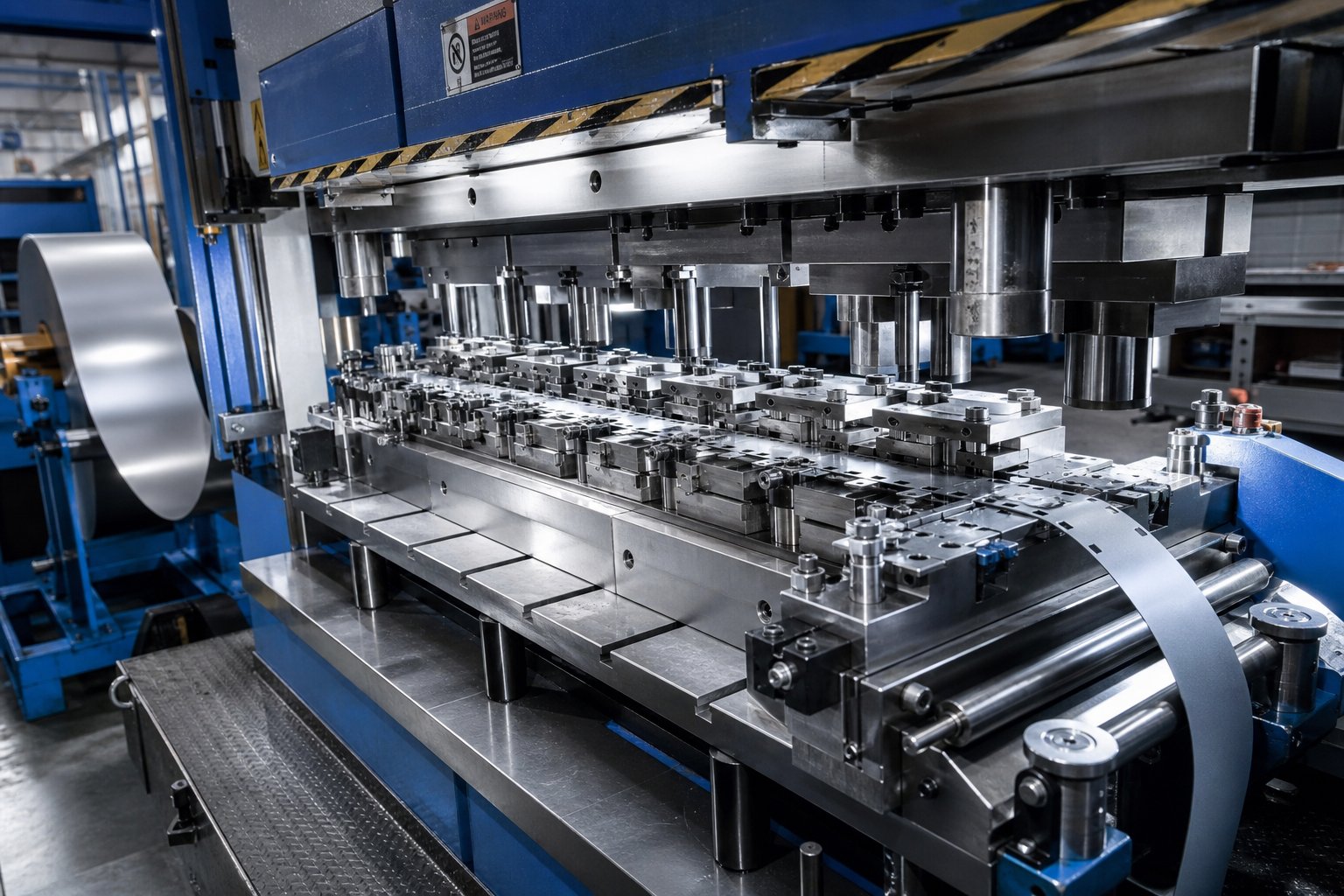
When production scales into hundreds of thousands or millions of parts per year, progressive dies become the workhorse. The metal stamping process in a progressive die works like this: a coil-fed strip advances through multiple stations inside a single tool. Each press stroke simultaneously performs a different operation - piercing at station one, notching at station two, forming at station three - and a finished part drops off at the final station every cycle.
The result is dramatically lower per-piece cost and minimal operator intervention. The tradeoff is a higher upfront tooling investment and a longer design-to-production lead time. But at scale, the ROI on a progressive die far outpaces running the same part across multiple single-station setups. This is where dies and stamping efficiency truly converge.
Transfer and Compound Dies
Some parts are too large or too deeply drawn to remain attached to a carrier strip. Transfer stamping solves this by cutting individual blanks and mechanically moving them from station to station within the press. Automotive body panels, cookware shells, and deep-drawn housings are typical candidates. You get the multi-station efficiency of progressive tooling without the geometric constraints of strip-fed material.
Compound dies take a different approach. They perform multiple cutting operations - blanking and piercing, for example - simultaneously in a single press stroke at one station. The stamping process in a compound die produces exceptionally flat, burr-free parts, making them ideal for washers, shims, and gaskets where flatness tolerance is critical.
| Die Type | Typical Volume Range | Part Complexity | Relative Lead Time | Relative Tooling Cost | Best ROI When... |
|---|---|---|---|---|---|
| Single-Station | Low to Medium | Simple (one operation) | Short | Low | Annual volumes stay under ~10,000 parts or secondary ops are needed |
| Progressive | High to Very High | Moderate to High (bends, forms, piercing) | Long | High | Volume exceeds ~50,000+ parts/year with repeating geometry |
| Transfer | Medium to High | Very High (large, deep-drawn) | Long | Very High | Parts are too large for strip or require deep draws |
| Compound | Low to High | Low (flat, multi-cut profiles) | Moderate | Medium | Flatness and concentricity matter more than forming complexity |
The financial logic is straightforward: higher tooling investment pays off only when volume amortizes it quickly enough. A progressive die that costs five to ten times more than a single-station setup can still deliver a lower total cost of ownership if annual demand justifies the automation. Conversely, over-investing in a complex transfer die for a low-volume part locks capital into tooling that never reaches its breakeven point.
Matching die architecture to your production reality is the first strategic decision. But even the right die type will underperform if its internal components are poorly specified - which brings us to what is actually inside the assembly and how each piece contributes to the stamping cycle.
Key Components Inside a Stamping Die Assembly
A stamping die set might look like a solid block of steel bolted into a press, but crack it open and you will find dozens of interdependent stamping die parts working in concert. When one component drifts out of spec, the entire system feels it - burrs appear, strips misfeed, and punches snap. Understanding how these pieces interact gives engineers and buyers a shared vocabulary for specifying tooling and diagnosing problems faster.
Upper and Lower Die Assemblies
Every metal die set starts with two structural halves: the upper shoe mounts to the press ram, and the lower shoe bolts to the press bed. These heavy steel plates serve as the foundation for every other component in the assembly. Think of them as the chassis - if they flex or shift under tonnage, nothing downstream stays in alignment.
Precision guide pins and bushings connect the two halves, maintaining alignment to within 0.0001 inches throughout the press stroke. Ball-bearing guide pins have become the industry standard for their ease of separation and consistent tracking. Punch holders and backing plates distribute impact loads across the upper shoe, preventing localized stress that would crack individual punches or deform mounting pockets.
Cutting and Forming Components
This is where the actual work happens. Sheet metal punches and dies interact at every station to cut, bend, and form the strip into its final geometry. Each component has a specific job within the stamping cycle:
- Punches - Press into the sheet metal to pierce holes or cut profiles; available in round, oblong, square, and custom nose shapes.
- Die buttons - Provide the opposing cutting edge that mates with the punch, offset by 5-10% of material thickness to create clean shear.
- Pilots - Tapered pins that locate the strip at each station, ensuring accurate pitch and feature position throughout the progression.
- Strippers (spring and solid) - Hold the strip flat during cutting and pull it free from the punch on the upstroke; spring strippers allow controlled clamping force while solid strippers offer rigidity for heavy blanking.
- Stamping die lifters - Raise the strip between stations to clear formed features and reduce drag, enabling smooth feed progression.
- Pressure pads - Apply controlled downward force during forming operations to prevent wrinkling and manage material flow into the die cavity.
- Die springs (mechanical and nitrogen) - Supply the force that operates strippers, lifters, and pressure pads; nitrogen gas springs deliver higher force in a compact package.
- Retainers - Secure punches and die buttons in position, enabling quick replacement without disassembling the entire stamp die set.
These stamping die components do not operate in isolation. Pilots locate the strip before punches engage. Strippers clamp the material flat so cutting is clean. After the press cycles, stamping die lifters raise the strip so it can advance to the next station without snagging on formed features. Each element depends on the one before it - miss a beat, and you get misfed strips or slug pulling.
Auxiliary Systems and Sensors
Modern metal press dies increasingly incorporate electronic monitoring as standard equipment rather than optional add-ons. Die protection systems detect material movement and critical events in real time, preventing misfeeds and costly die crashes. Common sensor types include:
- Misfeed detectors - Verify strip position before the press completes its stroke, halting the cycle if material has not advanced correctly.
- Slug sensors - Monitor slug ejection to confirm that cut material clears the die cavity, preventing slug buildup that damages cutting edges.
- Force monitors - Track tonnage per stroke to flag abnormal loads that indicate broken punches, material variation, or alignment drift.
These sensors transform a stamping die set from a passive tool into an actively monitored production asset. They protect your investment in hardened tooling while maintaining part quality across millions of cycles.
Of course, even perfectly specified components will underperform if the wrong material is behind them. The steel grade, heat treatment, and surface coating applied to each punch, button, and forming insert determine how long that precision lasts under production loads.
Die Materials and Coatings That Control Longevity
Steel stamping dies can hold tolerances for millions of cycles - or wear out in a few thousand hits. The difference often comes down to a single decision made early in the design phase: which stamping die steel goes into each cutting and forming station, and whether it receives a surface coating. Get this right and your tooling runs longer between sharpenings. Get it wrong and you are chasing burrs, galling, and premature punch failures from day one.
Tool Steel Grades for Different Applications
Not all tool steels behave the same way under press tonnage. Each grade trades off hardness, toughness, and wear resistance differently, which means the best choice depends on what the die is actually doing - high-speed blanking, heavy forming, or something in between.
Here are the four grades you will encounter most often in stamped steel production:
- D2 (high-carbon, high-chromium) - The go-to for cold-work blanking and piercing where abrasive wear is the primary failure mode. D2 delivers excellent edge retention and long run life on steel sheet stamping applications, but its moderate toughness makes it vulnerable to chipping under heavy shock loads.
- A2 (air-hardening) - Offers a balanced middle ground between wear resistance and toughness, with better dimensional stability during heat treatment than D2. A2 is a strong choice for forming dies and moderate-volume blanking where some impact resistance is needed alongside reasonable wear life.
- M2 (molybdenum high-speed steel) - Retains hardness at elevated temperatures, making it suited for high-speed progressive die stations where friction heat builds up rapidly. M2 excels in cutting applications that demand hot hardness without sacrificing wear resistance.
- S7 (shock-resisting) - Prioritizes toughness above all else. When a station experiences heavy impact - deep drawing, coining, or forming thick high-strength steel - S7 absorbs shock without cracking. Its wear resistance is lower, so it pairs best with coatings or is reserved for forming rather than cutting.
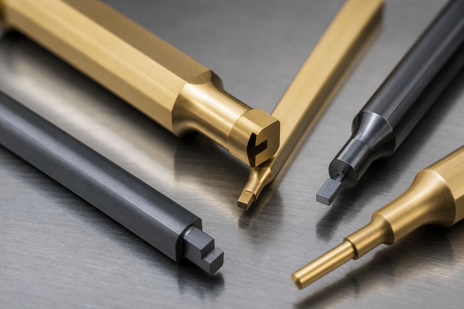
For extreme-wear stations where even D2 cannot keep up - think long-run progressive dies blanking abrasive materials - carbide stamping dies use tungsten carbide inserts. Carbide offers dramatically higher hardness and wear resistance than any tool steel, though at the cost of brittleness. You will typically see carbide inserts press-fit into steel holders at specific high-wear stations rather than building an entire die from carbide.
Surface Coatings That Extend Die Life
Even the best stamping die steel benefits from a surface coating that reduces friction and prevents workpiece material from adhering to tooling surfaces. PVD (physical vapor deposition) coatings add a thin, hard film - typically 2 to 10 microns - without significantly altering part dimensions or requiring post-coat grinding.
The most common options for steel stamping dies include:
- TiN (Titanium Nitride) - A general-purpose coating with a hardness around 2,200 HV. It reduces friction on carbon steel stamping and mild steel blanking, extending sharpening intervals for light-to-medium duty operations.
- TiCN (Titanium Carbonitride) - Harder than TiN at approximately 3,400 HV with a lower friction coefficient (0.2 versus 0.6 for TiN). TiCN is particularly effective for forming stainless steel, where adhesive wear and galling are the dominant failure modes.
- CrN (Chromium Nitride) - Features low internal stress, excellent adhesion, and high corrosion resistance. CrN works well on aluminum stamping dies where softer workpiece material tends to build up on uncoated tooling surfaces.
- DLC (Diamond-Like Carbon) - The lowest friction coefficient of any common PVD coating (below 0.1), with hardness reaching 4,000 HV. DLC excels on copper alloys and aluminum, where minimal surface interaction prevents galling entirely. Its maximum coating thickness is limited, so it is best suited for forming operations rather than heavy blanking.
Sounds complex? The selection logic is actually straightforward - match the coating to the workpiece material that causes the most trouble for uncoated tooling.
Matching Die Material to Workpiece Metal
Every sheet metal alloy imposes different stresses on the die. Cold rolled steel stamping at moderate gauge is relatively forgiving - D2 with TiN handles most applications. Stainless steel, on the other hand, is adhesive and work-hardens quickly, demanding higher-alloy steels and anti-galling coatings. High-strength steel generates massive forming loads that require shock-resistant grades. And aluminum, despite being soft, builds up aggressively on tool surfaces without proper lubrication and coating.
| Workpiece Material | Key Challenge | Recommended Die Steel | Recommended Coating | Notes |
|---|---|---|---|---|
| Mild / Carbon Steel (CRS) | Abrasive wear | D2 or A2 | TiN | Standard pairing for cold rolled steel stamping; long run life with basic maintenance |
| Stainless Steel (300/400 series) | Adhesive wear, galling | A2 or D2 (avoid high-Cr on high-Cr workpiece) | TiCN or AlCrN | Metallurgical similarity between D2 and stainless can cause micro-welding; TiCN barrier critical |
| High-Strength Steel / AHSS | Extreme forming loads, punch breakage | S7 (forming) or M2 (cutting) | TiAlN or TiCN | Toughness for forming stations; hot hardness for high-speed cutting stations |
| Aluminum Alloys | Material buildup, scoring | A2 or D2 | CrN or DLC | Low-friction coatings prevent aluminum adhesion; wider punch-to-die clearance needed |
| Copper / Brass Alloys | Galling, surface marking | D2 or A2 | DLC | Ultra-low friction prevents transfer; polished die surfaces extend coating effectiveness |
One detail that catches buyers off guard: punch-to-die clearance must also adjust by material. Softer metals like aluminum require less clearance (typically around 5% of material thickness per side), while high-strength steel demands more (up to 12-15%) to avoid excessive punch loading. Selecting the right stamping die steel and coating combination only works if the mechanical design accommodates the workpiece properties as well.
Material selection gives a die its potential lifespan. Realizing that potential, though, requires a design and build process that translates engineering intent into physical tooling without introducing new failure points along the way.
How Modern Stamping Dies Are Designed and Built
A stamping die quote is not just a price tag on a block of steel. Behind every lead time estimate and cost figure sits a multi-phase engineering workflow that transforms a 2D part print into hardened, press-ready tooling. Understanding this stamping die design process helps engineers set realistic expectations and gives sourcing managers the context they need to evaluate whether a supplier's timeline actually makes sense.
From Part Print to Die Concept Layout
Every stamping design project starts the same way: a designer receives a part print - complete with GD&T callouts, material specification, and production volume targets - and begins reverse-engineering how to make that geometry from flat sheet metal.
The first task is determining the process sequence. Which features get blanked first? Where do bends occur? Does the part require a draw? As Art Hedrick notes in The Fabricator, the exact number of process steps depends on the workpiece material, part complexity, and tolerancing requirements. A simple bracket may need four or five stations. A contoured automotive clip with multiple bends and lance features might demand fifteen or more.
For progressive dies, this analysis produces a strip layout - a plan view showing how the metal strip advances through every station. The strip layout defines:
- Station count and sequence of operations (pierce, notch, form, cutoff)
- Carrier web design - whether the strip stays flat (solid carrier) or requires flex carriers to accommodate height changes and material flow
- Scrap shedding strategy - how waste material exits the tool through clearance holes or off the sides
- Pitch distance - the exact advancement per press stroke that keeps features registered across stations
Strip utilization is where metal stamping die design directly impacts material cost. A nesting strategy that maximizes the number of parts per strip width reduces scrap percentage, sometimes dramatically. On a high-volume run of millions of parts, even a 2-3% improvement in material utilization can save tens of thousands of dollars annually. Designers balance this against the practical constraints of carrier strength - the carrier web must be rigid enough to feed the strip without buckling, especially on thin materials where stiffness is limited.
Idle stations (positions that perform no work) often appear in the concept layout as well. These allow room for stronger tooling sections, proper slug clearance, or simply enough physical space between complex forming operations. Skipping them to save die length usually backfires with maintenance headaches later.
CAE Simulation and Feasibility Analysis
Imagine investing six figures in hardened tooling, only to discover on the first trial run that the part wrinkles during draw or springs back beyond tolerance. A decade ago, that scenario was common. Today, finite element analysis (FEA) and forming simulation catch those problems before any steel is cut.
Sheet metal forming simulation uses computational models to predict how the blank behaves under press loads. The software accounts for material properties (yield strength, elongation, strain hardening), tool geometry, friction conditions, and process parameters like blank holder force and press speed. It then flags potential defects:
- Thinning and splits - Areas where material stretches beyond its forming limit, predicting where cracks would appear in physical trials
- Wrinkling - Zones of compressive instability, typically in flange areas or deep-draw corners where material flow is uncontrolled
- Springback - The elastic recovery that causes formed parts to deviate from intended geometry once press force is removed, particularly problematic with high-strength steels and aluminum alloys
Why does this matter for the overall stamping manufacturing process? Simulation compresses what used to be three or four physical prototype iterations into virtual cycles that run overnight. Each physical try-out can cost weeks of lead time and thousands in trial material. Eliminating even one iteration pays for the simulation software many times over.
Advanced solvers also predict minimum press force requirements, helping production planners confirm that the intended press has sufficient tonnage before dies manufacturing begins. Some platforms even simulate tool deflection under load, revealing how elastic deformation in the die itself might affect contact pressure and, consequently, part quality over long runs. This level of insight transforms the metal stamping manufacturing process from trial-and-error into a predictive discipline.
CNC Machining, Wire EDM, and Assembly
With a validated design locked in, the physical build begins. Tool & die manufacturing follows a sequence that preserves the dimensional precision established in CAD through every stage of material removal and hardening:
- Rough machining - CNC mills remove bulk material from die shoes, punch holders, and die blocks, leaving 0.010-0.020 inches of stock for finish operations. Modern high-speed machining centers run 3D tool paths generated directly from the CAD model, eliminating manual interpretation errors.
- Heat treatment - Components are hardened to their target Rockwell values (typically HRC 58-62 for cutting steels like D2, HRC 54-58 for forming steels). Vacuum heat treatment minimizes distortion and surface decarburization.
- Finish grinding - Surface grinders and cylindrical grinders bring hardened components to final dimensions and surface finish requirements. Flatness on die shoes is held to within 0.0002 inches across the full plate.
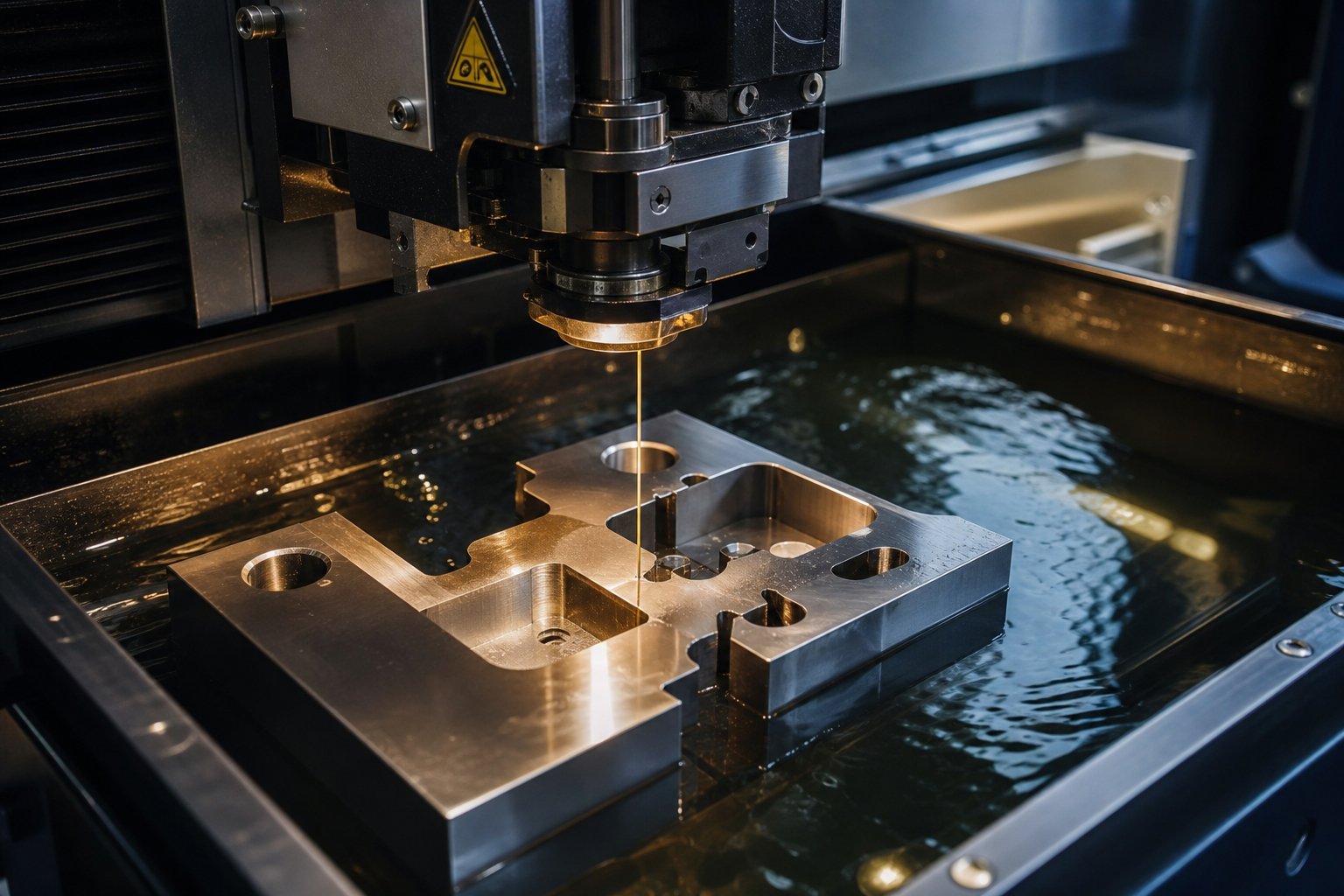
- Wire EDM - For complex punch and die opening profiles that cannot be economically ground, wire electrical discharge machining cuts hardened steel to tolerances of +/- 0.0001 inches. Wire EDM is essential for intricate blanking profiles, tight-radius die openings, and irregular piercing geometries.
- Final assembly and fit verification - All components mount into the die shoes. Punch-to-die alignment is verified with optical measurement or blue-dye contact checks. Guide pin and bushing clearance is confirmed. The completed assembly undergoes a shut-height check and dry-cycle verification before any material enters the tool.
The digital thread - from CAD model to CAM tool paths to CMM inspection reports - keeps manufacturing dies dimensionally consistent across every process step. When a wire EDM profile is programmed directly from the same 3D model used in forming simulation, there is no opportunity for transcription errors or manual reinterpretation. That continuity is what separates a precision stamping die from an assembly that needs weeks of hand-fitting at tryout.
For buyers, understanding this workflow explains why credible lead times for production-grade tooling typically run 8 to 16 weeks. Each phase builds on the last, and rushing one step - skipping simulation, short-cutting heat treatment, eliminating fit verification - creates problems that surface as failures during production. Those failures, and how to diagnose them before they cascade, are exactly what separates a well-maintained die from one that eats into your margins every shift.
Die Failure Modes and How to Prevent Them
A die can survive millions of cycles or start producing scrap within weeks. The difference rarely comes from a single catastrophic event. Most failures in metal stamping tooling develop gradually - wear accumulates, clearances shift, lubrication degrades - until the process crosses a threshold and parts suddenly fall out of spec. Knowing where to look first saves hours of press downtime and thousands in stamping tool repair costs.
Common Die Failure Modes and Root Causes
When quality slips mid-run, the instinct is to blame the obvious: a broken punch or a dull edge. But visible damage is usually the end stage of a chain reaction that started much earlier. As progressive die research shows, burr growth, slug pulling, feeding instability, and dimensional drift are often symptoms of the same underlying wear progression rather than isolated defects.
Consider punch breakage. A punch does not snap without warning - it chips first, often because lateral loading from guide wear or strip misalignment concentrates stress on one side of the cutting edge. Similarly, excessive burr formation signals that punching stamping edges have dulled beyond their effective shear geometry, increasing stripping resistance and raising the risk of slug pulling on the very next stroke.
Here are the failure modes you will encounter most frequently on a die stamping press, paired with root causes and corrective actions:
- Punch breakage or chipping - Root cause: misalignment, excessive clearance on one side, insufficient backing plate support, or wrong tool steel grade for the application. Corrective action: verify guide pin and bushing condition, check for uneven clearance distribution, confirm punch retention in holders, and evaluate whether the steel grade matches the workpiece hardness.
- Excessive burr formation - Root cause: worn cutting edges, insufficient punch-to-die clearance, or delayed sharpening intervals. Corrective action: inspect edge condition on stamping die punches and die buttons, measure actual clearance with feeler gauges, and establish sharpening schedules based on stroke count rather than visual inspection alone.
- Slug pulling - Root cause: vacuum adhesion between punch face and slug, worn punch edges increasing stripping resistance, or poor scrap evacuation. Corrective action: add air blow systems or spring ejectors, verify slug drop paths are clear, and restore punch edge condition through regrinding.
- Galling (material pickup on die surfaces) - Root cause: inadequate lubrication, tight forming clearances, surface roughness on die contact areas, or metallurgical similarity between die and workpiece materials. Corrective action: polish affected die surfaces, verify lubricant delivery reaches contact zones, widen draw clearances where material thickens, and consider anti-galling coatings like TiCN or DLC.
- Premature wear across multiple stations - Root cause: strip positioning instability from worn pilots, guide degradation, or feed timing errors that create cumulative stress on downstream components. Corrective action: inspect pilot pin condition and pilot hole elongation, verify feed release timing, and check stamping die clamps and strip support structures for looseness.
You will notice a pattern: most failures trace back to alignment, clearance, lubrication, or timing - not a sudden material defect. That interconnectedness is exactly why experienced tool stamping metal shops treat these root causes as a system rather than chasing individual symptoms.
Clearance and Tolerance Fundamentals
Punch-to-die clearance is the single most influential variable in cutting performance. It is typically expressed as a percentage of material thickness per side - meaning a 10% clearance on 0.060-inch stock translates to 0.006 inches of space between the punch edge and the die opening on each side.
The traditional 10% rule was established when most pressrooms ran low-carbon steel exclusively. It remains a reasonable starting point for mild steel, but applying it universally creates problems. Higher-strength steels fracture with less deformation, so they often perform better with slightly more clearance (12-15%) to reduce punch loading and shock. Softer metals like aluminum or copper need less clearance (5-8%) because they deform more before fracture, and excessive clearance creates rollover and tearing instead of clean shear.
When clearance is too tight, you get increased cutting force, accelerated edge wear, higher stripping resistance, and elevated punch temperatures. When clearance is too wide, expect excessive burr on the die side, edge rollover, dimensional variation, and rough cut surfaces. Either condition shortens the interval between sharpening cycles and drives up your per-piece cost through scrap and unplanned maintenance.
Clearance also changes over the die's life. As cutting edges wear and are resharpened, the effective clearance shifts slightly - particularly if grinding removes more material from one component than the other. Tracking cumulative grind depth and compensating with shims keeps the process stable across the tool's full service life.
Preventive Maintenance Planning
Reactive maintenance - waiting until parts go bad to open the die - is the most expensive metal stamping technique you can practice. A structured preventive schedule keeps wear predictable and catches degradation before it reaches the part.
An effective framework covers four areas on overlapping intervals:
- Sharpening intervals (stroke-count-based) - Establish regrind triggers from actual production data rather than arbitrary calendars. Track burr height trends and stripping force. Best-practice programs use consistent hits-per-service targets to maintain stable cutting loads and lower stripping resistance.
- Component inspection (shift, daily, weekly) - Check pilots, guides, springs, and retainers at every PM stop. Spring replacement should trigger when free length drops more than 10% or cracking appears. Guide pins and bushings need lubrication and scoring inspection at every teardown.
- Lubrication verification (per shift) - Confirm that lubricant reaches all intended contact zones, especially narrow piercing stations and deep forming areas where localized starvation occurs even when the overall system appears functional. Insufficient lubrication causes galling, heat buildup, surface pickup, and accelerated guide wear.
- Spare-parts inventory (planned) - Stock consumable components - punches, die buttons, springs, pilots, and wear plates - based on historical replacement frequency. Running out of a critical insert mid-run forces improvisation that rarely ends well.
Proper maintenance can extend die life by multiples of the original service interval. The difference between a die that runs two million hits before rebuild and one that fails at 200,000 is rarely the initial build quality alone - it is the discipline of catching wear while corrective action is still cheap and simple.
Knowing how to keep a die running is half the equation. The other half - specifying the right die in the first place so that maintenance stays manageable and production targets stay realistic - depends on what information makes it into the RFQ package.
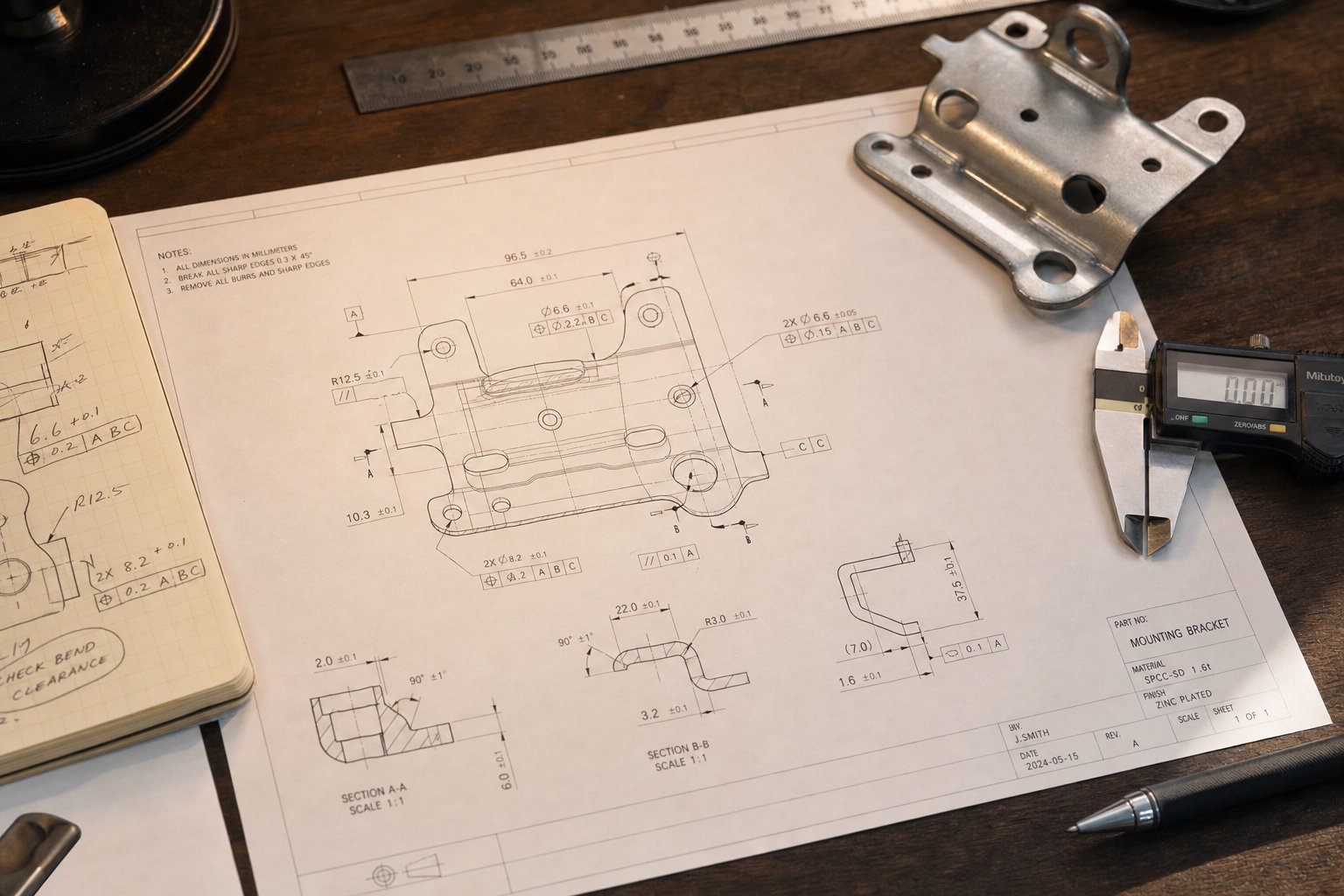
How to Specify a Stamping Die for Procurement
A die that fails in production often traces back not to build quality but to what was - or was not - communicated during the quoting stage. Incomplete RFQ packages force die makers to guess at tolerances, press constraints, or volume expectations. Those guesses show up later as tooling that underperforms, runs over budget, or misses delivery dates entirely. Whether you are sourcing custom metal stamping dies for a new product launch or replacing aging tooling, a complete specification package is the fastest path to an accurate quote and a die that actually works.
Essential Information for a Die RFQ Package
Think of your RFQ as the blueprint that a die maker uses to price, plan, and build your tooling. Missing even one critical input can skew the quote or introduce design assumptions that conflict with your production reality. Here is what a complete package includes:
- Part print with GD&T - A fully dimensioned drawing including geometric dimensioning and tolerancing callouts, datum structure, and critical-to-function features clearly identified.
- Material specification and thickness - Exact alloy grade (e.g., ASTM A1008 CR, 304 SS, 5052-H32 aluminum), nominal thickness, and acceptable thickness range.
- Annual volume projection - Expected yearly demand and total program life quantity; this drives die class selection, material choices, and maintenance planning.
- Press specifications - Tonnage capacity, bed size, stroke length, shut height range, feed type, and any automation constraints (coil width limits, transfer rail spacing).
- Required tolerances and critical dimensions - Which features demand tight process control versus which can accept standard blanking tolerances. As industry case studies show, over-tolerancing non-critical features can inflate tooling cost by 20% or more.
- Secondary operations - Any downstream processes (tapping, welding, plating, assembly) that affect how stamping parts exit the die or impose burr-direction requirements.
Providing this information upfront eliminates the back-and-forth that delays quoting. It also gives the die maker enough context to flag potential manufacturability issues early - before tooling dollars are committed.
Volume Projections and Die Class Selection
Annual volume is not just a line item on the RFQ. It determines the entire tooling strategy. A custom metal stamping die built for 5,000 parts per year looks fundamentally different from one designed to produce 5 million.
Die class ranges from prototype-grade soft tooling (aluminum or mild steel die components, minimal hardening) through Class A hardened production dies built from premium tool steels with carbide inserts at high-wear stations. Higher die class means greater upfront investment but lower per-piece cost and longer service life - the same financial tradeoff discussed in die type selection, now applied at the component level.
For a sourcing manager evaluating a custom metal stamping tool program, the key question is breakeven: at what annual volume does the added tooling investment pay for itself through reduced maintenance, fewer sharpenings, and longer intervals between rebuilds? A qualified supplier will walk you through that analysis rather than defaulting to the most expensive option.
Evaluating Feasibility and Supplier Capability
A complete RFQ package gets you an accurate quote. But a quote alone does not guarantee producible metal stamping components. The gap between quoted geometry and production-ready stamping parts is bridged through feasibility validation - and not every supplier invests in this step.
A capable die maker uses CAE forming simulation to verify that your part geometry, material, and tolerances are achievable before committing to final die design. Trial runs on a tryout press then confirm what simulation predicted, catching springback variations or material-flow issues that only surface under real press conditions.
Manufacturers like YICHEN structure their workflow around this full pathway - feasibility analysis and CAE simulation through precision machining, trial runs, and final CMM inspection - under one roof. For sourcing managers and tooling engineers, that end-to-end capability means a single point of accountability from custom stamping dies specification through validated production tooling, reducing coordination overhead and compressing the timeline from RFQ to first article approval.
The specification and feasibility process narrows the field of potential suppliers. But choosing the right die partner requires evaluating capabilities beyond quoting - the equipment, quality systems, and technical depth that determine whether your tooling performs as promised once it hits the production floor.
Choosing the Right Stamping Die Partner
You can specify the perfect RFQ package, select the ideal die architecture, and nail down material and coating choices - but all of that precision evaporates if the supplier building your tooling lacks the technical depth to execute. Evaluating stamping die manufacturers goes beyond comparing quoted prices. It means auditing the equipment, systems, and engineering capacity that determine whether your metal stamping dies perform as designed once they hit production speed.
Technical Capabilities to Evaluate
A die maker's shop floor tells you more than their sales deck. When you walk through a facility - or review their capability documentation - look for evidence of vertical integration. Suppliers that handle design, simulation, machining, and tryout under one roof eliminate the coordination gaps that introduce errors when multiple vendors handle different phases.
Here is what matters most when evaluating any metal stamping die manufacturer:
- In-house die design and CAD/CAM capacity - Confirms the supplier owns their engineering output rather than outsourcing concept work that disconnects design intent from build execution.
- CAE forming simulation tools - Validates feasibility before steel is cut, reducing prototype iterations and compressing lead time.
- CNC machining centers (3-axis and 5-axis) - Provides the rough and finish machining precision that holds die block and punch holder tolerances throughout the build.
- Wire EDM capability - Essential for complex punch profiles and die openings where conventional grinding cannot achieve the required geometry or tolerance.
- Jig grinding and surface grinding - Delivers the final dimensional accuracy on hardened components that determines punch-to-die clearance consistency.
- CMM inspection and metrology lab - Verifies every critical dimension against the part print before the die leaves the shop, providing traceable first-article data.
- Trial press availability - Allows the die maker to validate tooling performance with actual material under real press conditions, catching issues before shipment rather than during your production ramp.
Why does vertical integration matter so much? Every handoff between vendors introduces interpretation risk. When one shop designs the die, another machines the components, and a third assembles and tries it out, dimensional intent drifts at each transition. A single-source stamping dies manufacturer controls that chain from start to finish.
Quality Systems and Industry Standards
Technical capability without quality discipline produces inconsistent results. The certifications a supplier holds signal their commitment to process control and continuous improvement - particularly for stamping dies destined for automotive or aerospace programs where traceability is non-negotiable.
Two frameworks matter most when evaluating die manufacturers:
- ISO 9001 quality management system - Establishes documented procedures for design review, process control, inspection, and corrective action. As precision tooling specialists note, ISO 9001 certification demonstrates a manufacturer's ability to consistently produce products meeting both regulatory and customer requirements.
- NAAMS (North American Automotive Metric Standard) - Defines standardized die component specifications maintained by major OEMs. Stamper dies and components conforming to NAAMS standards ensure interchangeability and simplify maintenance across multiple tooling programs.
For automotive applications, OEMs maintain approved vendor lists that dictate which metal stamping die manufacturers a Tier 1 supplier can source from. Getting on - and staying on - those lists requires documented quality systems, regular audits, and demonstrated process capability. Aerospace programs add AS9100 requirements that layer flight-critical traceability onto the quality framework.
From Research to RFQ-Ready Decision
Everything covered in this article - die types, component anatomy, material selection, design workflow, failure prevention, and procurement specification - feeds into a single practical decision: which partner gets your tooling program?
The evaluation criteria above apply universally when assessing any die supplier. But finding a partner that covers the full spectrum - feasibility analysis, CAE simulation, precision machining, trial runs, and final CMM inspection under one roof - dramatically reduces your project risk. YICHEN offers exactly this end-to-end capability for manufacturers seeking a single-source partner for custom stamping dies. Their integrated workflow takes tooling engineers and sourcing managers from initial feasibility through validated production tooling without the coordination overhead of managing multiple vendors.
When you are ready to move from research to action, bring a complete RFQ package (part print, material spec, volume, press details) and ask prospective suppliers to walk you through their process - from simulation results to trial-run data. The metal stamping die manufacturers who can show you that full pathway, backed by quality certifications and inspection records, are the ones worth committing your tooling budget to.
Stamping Tool Die FAQs
1. What is a stamping tool die and how does it work?
A stamping tool die is a precision-engineered assembly of hardened components - including a punch, die block, stripper plate, and guide system - mounted inside a press. When the press cycles, it applies controlled force to cut, bend, or form flat sheet metal into net-shape parts. Unlike molds that shape liquid or pliable materials, stamping dies reshape solid metal at room temperature through mechanical force, enabling repeatable production of identical components with tolerances as tight as 0.0002 inches.
2. What are the main types of stamping dies and when should each be used?
The four main types are single-station dies, progressive dies, transfer dies, and compound dies. Single-station dies handle one operation per stroke and suit low-to-medium volumes under roughly 10,000 parts per year. Progressive dies carry a strip through multiple stations in one stroke, offering the lowest per-piece cost for volumes exceeding 50,000 parts annually. Transfer dies move individual blanks between stations for large or deeply drawn parts. Compound dies perform multiple cutting operations simultaneously for flat, high-precision parts like washers and shims.
3. How do you prevent common stamping die failures like burrs and punch breakage?
Most stamping die failures trace back to alignment, clearance, lubrication, or timing issues rather than sudden material defects. Preventing punch breakage requires verifying guide pin condition, checking clearance distribution, and matching tool steel grade to workpiece hardness. Excessive burrs are controlled by maintaining proper punch-to-die clearance (typically 5-15% of material thickness per side depending on material type) and establishing sharpening schedules based on stroke count data. A structured preventive maintenance program covering sharpening intervals, component inspection, lubrication verification, and spare-parts inventory can extend die life significantly.
4. What information should be included in a stamping die RFQ package?
A complete RFQ package includes six critical inputs: a fully dimensioned part print with GD&T callouts, exact material specification and thickness, annual volume projection and program life quantity, press specifications (tonnage, bed size, stroke length, shut height), required tolerances with critical dimensions identified, and any secondary operations like tapping or plating. This information allows die makers to accurately price tooling, select appropriate die class, and flag manufacturability issues early. Suppliers like YICHEN use this data to run CAE feasibility simulations before committing to final die design.
5. Which tool steel grades and coatings are best for stamping dies?
The optimal combination depends on your workpiece material. D2 tool steel with TiN coating handles most carbon steel blanking applications. Stainless steel demands A2 or D2 paired with TiCN coating to prevent galling. High-strength steels require S7 for forming stations (toughness) or M2 for cutting stations (hot hardness), combined with TiAlN coating. Aluminum stamping benefits from A2 or D2 with CrN or DLC coatings to prevent material buildup. Carbide inserts serve extreme-wear stations where even premium tool steels cannot maintain adequate edge life.


