


What Precision Stamping Dies Are and Why They Matter
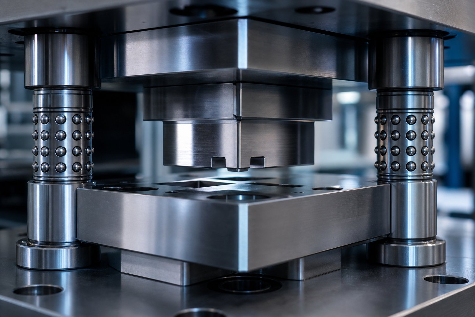
A precision stamping die is a custom-engineered tool used in a stamping press to cut, form, or shape sheet metal into high-accuracy parts while holding tolerances tighter than ±0.05 mm across millions of production cycles. Unlike general stamping tooling designed for looser dimensional requirements, these dies demand tighter punch-to-die clearances, superior tool steels, and advanced guidance systems to deliver repeatable accuracy at production speed.
Defining Precision Stamping Dies
Imagine a tool that must reproduce the same part geometry, within microns of deviation, whether it is stamping part number one or part number one million. That is the core challenge precision stamping dies solve. The die consists of two mating halves: a punch that moves and a die block that remains stationary. When sheet metal is fed between them, the punch applies force to shape or cut the material into a specific form. What elevates this tooling from standard to precision is the engineering behind every surface, clearance, and alignment feature.
Precision die tolerance requirements typically range from ±0.01 mm to ±0.05 mm, depending on the application. Achieving this level of accuracy is not a single-variable problem. It is a systems-engineering outcome where die design, press selection, material choice, and maintenance strategy all interact. A flaw in any one element degrades the performance of the whole system, no matter how well the other elements are executed.
Why Precision Matters in High-Volume Stamping
When you are producing hundreds of thousands of parts, even small dimensional drift creates compounding problems. A burr that grows by 0.02 mm over a production run might seem harmless in isolation, but downstream it causes assembly interference, connector failures, or out-of-spec rejection at incoming inspection. Scrap rates climb. Line stoppages multiply. Costs escalate in ways that far exceed the original tooling investment.
Precision at the die level is not a luxury specification. It is the foundation that cascades into product reliability, assembly consistency, and total manufacturing cost across every part the die produces.
This is why high accuracy stamping tooling cannot be evaluated by die cost alone. The real question is whether the die can maintain its target tolerances throughout its intended production life, and that depends on how well every element of the system works together. Die type, material grade, press capability, and maintenance protocol each play a role in that answer.
Precision vs Standard Stamping Dies
So what exactly makes a die "precision" rather than "standard"? The answer is not a single specification or a marketing label. It is a series of deliberate engineering decisions that compound across the entire tool, from material selection to surface finish to the guidance systems holding everything in alignment. Understanding these differences helps you avoid two costly mistakes: over-specifying tooling for parts that do not need it, or under-specifying for parts that do.
Tolerance Ranges and Repeatability Standards
The most visible distinction is tolerance capability. Standard stamping dies typically operate within a tolerance range of ±0.1 mm to ±0.5 mm, which covers a wide range of general-purpose applications such as brackets, enclosures, and structural hardware. Precision stamping dies, by contrast, target tolerances from ±0.01 mm to ±0.05 mm, with some ultra-precision applications pushing below ±0.01 mm for micro-connectors and medical components.
But here is the nuance that a stamping die tolerance comparison alone misses: the true differentiator is not the tolerance on the first part off the press. It is repeatability over production volume. A standard die might hit a tight dimension on its first hundred strokes, only to drift as wear accumulates. Precision tooling is engineered to hold its target specification across hundreds of thousands or millions of cycles because every element of the die, from the steel grade to the surface coating, is selected to resist the specific wear mechanisms that cause dimensional drift.
Design and Build Complexity Differences
Tighter tolerances demand tighter engineering at every level of the die. You will notice several key differences when comparing precision die clearance requirements and construction to standard tooling:
- Punch-to-die clearances: Precision dies use clearances as small as 3-5% of material thickness, versus 8-12% or more for standard dies. This tighter gap produces cleaner cut edges and more consistent part dimensions, but it also demands higher-quality components that can maintain that gap under load.
- Tool steel grades: Standard dies often use common tool steels like Cr12MoV or basic D2 variants. Precision dies step up to high-performance grades such as DC53, SKD11, or powder metallurgy steels that offer superior toughness, wear resistance, and dimensional stability under thermal cycling.
- Surface finishes: Critical surfaces on precision dies are ground and polished to mirror finishes, reducing friction-induced wear and preventing material adhesion (galling) that would otherwise degrade part quality over time.
- Guidance systems: Standard dies may rely on basic guide posts and bushings. Precision tooling incorporates ball-bearing guide systems, precision alignment mechanisms, and pilot pins that maintain positional accuracy within microns, stroke after stroke.
- Manufacturing processes: Precision dies require wire EDM for intricate punch and die profiles, precision grinding for datum surfaces, and tighter inspection protocols. Punches and dies are often cut to ±0.001 mm during manufacture.
These differences are not independent upgrades. They function as a system: a tighter clearance only delivers its benefit if the guidance system holds alignment, and the guidance system only maintains accuracy if the tool steel resists wear. Remove one link and the precision chain breaks.
When Standard Dies Are Sufficient
Precision tooling is not always the right answer. Honest engineering means recognizing when standard dies serve the application perfectly well and spending more would be waste rather than investment. Standard tooling is typically sufficient in these scenarios:
- Large structural parts with generous tolerances: Brackets, housings, and panels where ±0.1 mm or looser is acceptable rarely justify precision die cost.
- Low-volume prototyping: When annual production sits below 20,000 parts and the design may still change, simpler tooling or even wire EDM blanks make more economic sense.
- Non-critical cosmetic applications: Parts where fit and function are not tolerance-driven, like decorative covers or non-mating components.
The decision comes down to matching tooling investment to part requirements. Over-tolerancing parts that do not need it drives unnecessary cost into every stage of die manufacture and maintenance.
| Dimension | Standard Stamping Dies | Precision Stamping Dies |
|---|---|---|
| Typical Tolerances | ±0.1 mm to ±0.5 mm | ±0.01 mm to ±0.05 mm |
| Die Materials | Common tool steels (Cr12MoV, basic D2) | High-performance steels (DC53, SKD11, powder metallurgy, carbide inserts) |
| Guidance Systems | Standard guide posts and bushings | Ball-bearing guides, precision alignment mechanisms, pilot pins |
| Surface Finish | Standard machined | Precision ground and polished |
| Production Volume Suitability | Low to moderate volumes; simple geometries | High-volume runs (100,000+ cycles); complex, tolerance-critical parts |
| Punch-to-Die Clearance | 8-12% of material thickness | 3-5% of material thickness |
| Relative Cost | Lower upfront investment | Higher upfront cost; lower per-part cost at volume due to reduced scrap and longer die life |
The standard vs precision tooling cost conversation often fixates on upfront investment, but it should focus on total cost per acceptable part over the die's life. A precision die that costs twice as much but runs three times longer with half the scrap rate delivers far better economics for high-volume, tolerance-critical production. The real question is not "which die costs less" but "which die matches my part requirements, volume, and quality expectations." And answering that question well requires understanding the types of precision dies available and how to select among them.
Types of Precision Stamping Dies and How to Choose
Selecting the right die type is as consequential as selecting the right tolerance band. Two dies built to identical precision standards can deliver vastly different results if one is the wrong architecture for the part geometry, production volume, or material. The challenge is that most guidance on this topic treats die types as isolated categories rather than options within a decision framework. Here is how to approach that decision with engineering discipline.
Progressive Dies for High-Volume Complex Parts
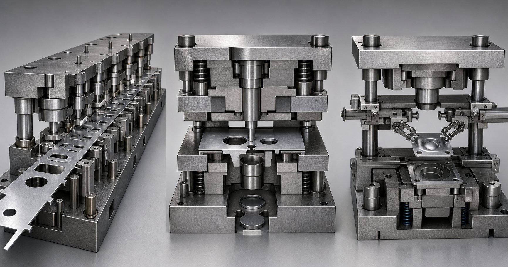
A progressive die is a strip-fed, multi-station tool where coil material advances through a sequence of operations, each station adding a feature: a cut, a bend, a form, a pierce. By the time the strip reaches the final station, the finished part is separated from the carrier strip. This architecture makes it the dominant choice as a progressive die for high volume stamping of moderately complex parts.
Why does it excel in precision applications? Each station handles a single operation, which means punch-to-die clearances and alignment can be optimized independently for each cut or form. Station sequencing also allows engineers to manage springback by distributing forming operations across multiple steps rather than forcing all deformation into a single stroke. The result is tighter dimensional control on the finished part, even for geometries that would be difficult to hold in a single operation.
Progressive dies can produce anywhere from seven or eight parts per minute to 1,500 parts per minute, and they often run unattended once properly set up. HVAC components such as small brackets, heat exchanger fins, and connector terminals are common application examples where progressive stamping combines high volume with the repeatability that precision demands.
The tradeoff: initial tooling cost is higher than simpler die types, and damage to a single station requires removing the entire die set for repair. Progressive dies also require a coil feeder system and an open-ended press to allow strip feeding.
Compound and Combination Dies for Flatness-Critical Parts
When you need a compound die for flatness-critical parts, the architecture shifts fundamentally. A compound die performs multiple cutting operations in a single press stroke, producing the finished blank in one hit. Because all features are cut simultaneously relative to the same datum, the part exits the die with exceptional positional accuracy between features and minimal distortion.
This makes compound dies ideal for washers, gaskets, shims, and any component where flatness and concentricity matter more than geometric complexity. The single-stroke approach minimizes misalignment risk between operations and generates less scrap material compared to multi-station methods.
Combination dies extend this concept by adding a forming operation (such as a shallow draw or emboss) to the cutting operations within the same stroke. They occupy a middle ground between compound dies and progressive dies: more capable than a pure compound die, but without the complexity and cost of a full progressive tool.
The limitation is production speed. Compound and combination dies are generally slower than progressive dies and are better suited for moderate volumes where part precision outweighs throughput concerns.
Transfer Dies for Large or Deep-Drawn Parts
Some parts are simply too large, too deep, or too geometrically complex for strip feeding. Transfer dies solve this problem by mechanically moving individual blanks from station to station using traveling rails with gripper fingers, rather than relying on a connected strip carrier.
In a progressive die vs transfer die selection, the deciding factor is often part size and draw depth. Transfer systems handle three-axis motion: moving inward to grip the part, lifting it vertically, advancing it to the next station, and lowering it into position. This flexibility allows parts to be turned over or rotated during the transfer process, enabling forming sequences that would be impossible with strip-fed tooling.
For very large parts, tandem press line setups place individual dies in separate presses arranged in sequence. Servo-driven transfer systems can be programmed to accommodate different parts, press speeds, and stroke lengths, adding flexibility for mixed-production environments.
Transfer dies do not tie parts together in a strip, which often yields material savings on larger blanks. However, they require more complex automation, additional die protection sensors, and a blank destacking system to feed individual pieces into the first station.
How to Choose the Right Stamping Die Type
Choosing among these options is not a single-variable decision. Use this sequence to narrow the field systematically:
- Part complexity: Simple flat parts with multiple holes point toward compound dies. Moderate complexity with sequential features favors progressive dies. Deep draws or large 3D geometries require transfer dies.
- Annual volume: High-volume runs (100,000+ parts) justify progressive die investment. Moderate volumes may favor compound or combination dies. Transfer dies suit both short and long runs depending on part size.
- Tolerance requirements: Flatness-critical parts benefit from compound dies. Tight positional tolerances across multiple features are achievable through progressive die station sequencing. Transfer dies maintain precision through controlled three-axis part handling.
- Material thickness: Thin materials feed well through progressive dies. Thicker stock or blanks requiring deep drawing are better candidates for transfer systems.
- Cost constraints: Progressive dies have the highest upfront cost but lowest per-part cost at volume. Compound dies offer lower tooling cost for simpler geometries. Transfer dies carry higher operational costs but save material on large parts.
No single die type is universally superior. The right answer emerges from matching part requirements to die architecture, then engineering that architecture to the precision level the application demands. And that engineering, regardless of die type, begins with the same question: how will this tool be designed and built to hold micron-level accuracy across its production life?
How Precision Stamping Dies Are Designed and Built
Every precision stamping die starts as a set of engineering constraints: part geometry, material properties, production volume, and a tolerance band that cannot be violated over the tool's entire service life. The precision stamping die design process transforms these constraints into physical tooling through a sequence of stages, each carrying decisions that either build accuracy into the system or introduce error that cannot be corrected later. Here is how that process unfolds, from the first CAD sketch to the final validated production tool.
CAD Design and Strip Layout Optimization
Strip layout is where material efficiency and part precision either align or compete. In a progressive die, the strip layout defines how the coil material advances through each station, where cuts and forms occur, and how much carrier material connects the part to the strip between operations. Stamping die strip layout optimization is fundamentally a balancing act: tighter nesting reduces scrap percentage but can crowd stations together, limiting the space available for forming operations and pilot pin positioning.
Engineers evaluate multiple nesting orientations and pitch distances using CAD software, looking for the layout that maximizes material utilization without compromising the station spacing needed for accurate forming. A layout that saves 3% on material but forces forming stations too close together can introduce strip distortion that degrades dimensional accuracy across every part.
Die clearance calculations happen in parallel with strip layout work. The gap between punch and die directly influences edge quality, burr formation, and die longevity. Too tight and the punch wears prematurely from excessive lateral pressure. Too loose and the cut edge degrades with rollover and increased burr height. For precision applications, clearance is typically calculated as a percentage of material thickness, adjusted for workpiece hardness and tensile strength. Getting this number right at the design stage prevents problems that no amount of downstream adjustment can fix.
CNC Machining, Wire EDM, and Precision Grinding
Once the design is locked, manufacturing follows a deliberate sequence where each process contributes a specific level of accuracy to the finished tool. Understanding how stamping dies are manufactured means understanding why this sequence matters.
CNC machining handles the initial rough shaping of die blocks, punch holders, and structural components. It establishes the overall geometry with tolerances in the ±0.01 mm to ±0.02 mm range, sufficient for non-critical surfaces but not for the working edges that contact the sheet material.
Wire EDM for stamping die manufacturing takes over where CNC reaches its limits. A thin electrically charged wire cuts through hardened tool steel with no mechanical contact, producing intricate punch and die profiles with tolerances down to ±0.005 mm. This process is essential for complex contours, tight inside radii, and any geometry where conventional machining would introduce tool deflection or thermal distortion. Wire EDM also cuts fully hardened material, which means components can be heat-treated to final hardness before profiling, eliminating the dimensional changes that heat treatment would otherwise introduce.
Precision surface grinding finishes the sequence. Critical datum surfaces, shut heights, and mating faces are ground to flatness and parallelism within microns. These surfaces serve as the reference planes that all other die components align to during assembly. If they are not flat and parallel, no amount of shimming will produce consistent results.
Assembly, Alignment, and Tryout
Individual components, each manufactured to tight specifications, must come together as an integrated system. Assembly begins with the die set: guide posts are fitted, die blocks are located on ground datum surfaces, and punches are installed with controlled clearances verified by feeler gauges or optical measurement.
Shimming plays a critical role here. Engineers adjust the clearance between punch and die by adding or removing precision shims, fine-tuning the gap that the design specified. Ball-bearing guide posts maintain vertical alignment between upper and lower die halves within microns of travel, ensuring that the punch enters the die opening in exactly the same position on every stroke.
The die tryout and validation process then begins with progressive sample runs on the production press or a dedicated tryout press. Initial strokes are run at reduced speed, with parts measured against the dimensional print at each station. Engineers check for burr height, edge condition, dimensional accuracy, and forming quality, adjusting timing, shut height, and spring pressures as needed.
CAE simulation tools have significantly reduced the number of physical tryout iterations required. Forming simulation software predicts material flow, thinning, and wrinkling before the die is ever built. Springback prediction, using advanced material models such as the Yoshida-Uemori kinematic hardening model, allows engineers to compensate for elastic recovery in the die geometry itself. Without accurate springback data, formed parts can deviate significantly from nominal dimensions, a problem that historically required multiple rounds of physical die rework to resolve.
These simulation capabilities do not eliminate tryout, but they compress it from weeks to days. The first physical samples come off closer to print, and corrections are smaller and more predictable. For engineering teams working with advanced high-strength steels, where springback behavior is complex and nonlinear, simulation is not optional. It is the difference between a controlled development process and an expensive guessing game.
By the time a precision die clears validation, every surface, clearance, and alignment feature has been verified against specification. The tool is production-ready. But "production-ready" is not a permanent state. The materials and coatings that make up the die's working surfaces determine how long that readiness lasts under the punishing repetition of high-volume stamping.
Die Materials and Coatings That Drive Longevity
A die that passes validation on day one only delivers value if it holds those same tolerances across its full production life. The working surfaces of a precision stamping die endure millions of impacts, each one generating friction, heat, and compressive stress. How long those surfaces maintain their geometry depends almost entirely on two decisions: what the die is made from and what coating protects it. Die material selection for high volume stamping is not about picking the hardest steel available. It is about matching material properties to the specific failure mechanism most likely to end the die's useful life.
Tool Steel Grades and Their Applications
Which is the best tool steel for stamping dies? The answer depends on how the die fails. Edges might wear progressively, deform under load, or chip from repeated impact. Identifying the dominant mechanism is the starting point for material selection.
Here is how the most common grades map to production conditions:
- AISI D2 (SKD11): The workhorse for high-volume blanking and cutting. D2's high chromium carbide content gives cutting edges exceptional wear resistance, allowing them to retain geometry over long production runs. Working hardness ranges from 58-60 HRC. It excels when tool life is limited by abrasive or adhesive wear, but once edge chipping appears, a tougher grade is needed.
- AISI A2 (SKD12): Selected when no single failure mode dominates. A2 provides a balance between wear resistance and toughness at 58-62 HRC, making it suitable for progressive dies where multiple stations experience different loading conditions simultaneously. In a D2 vs A2 tool steel for die making decision, A2 wins when mixed conditions are present and edge chipping risk is moderate.
- AISI M2 (SKH51): Applied where both wear and compressive stress contribute to failure. M2 operates at 60-65 HRC and provides better resistance to deformation than D2 while maintaining higher wear resistance than shock-resistant grades. It is commonly used for punches that must hold edge strength under repeated high-load stamping.
- AISI S7: The go-to choice when chipping, cracking, or fatigue from repeated impact limits tool life. At 56-58 HRC, S7 absorbs cyclic impact stresses that would fracture higher-carbide steels. Heavy-gauge stamping and high-load punching stations benefit most from this grade.
For ultra-high-volume applications exceeding several million cycles, conventional tool steels may not deliver adequate life. Powder metallurgy (PM) steels such as CPM 10V and Vanadis 4 Extra offer finer, more uniformly distributed carbides that improve both toughness and wear resistance beyond what conventional melted steels achieve. Tungsten carbide inserts take this further, providing extreme hardness for cutting edges in applications where even PM steels wear too quickly, though their brittleness demands careful die design to prevent fracture under impact loading.
Surface Coatings That Extend Die Life
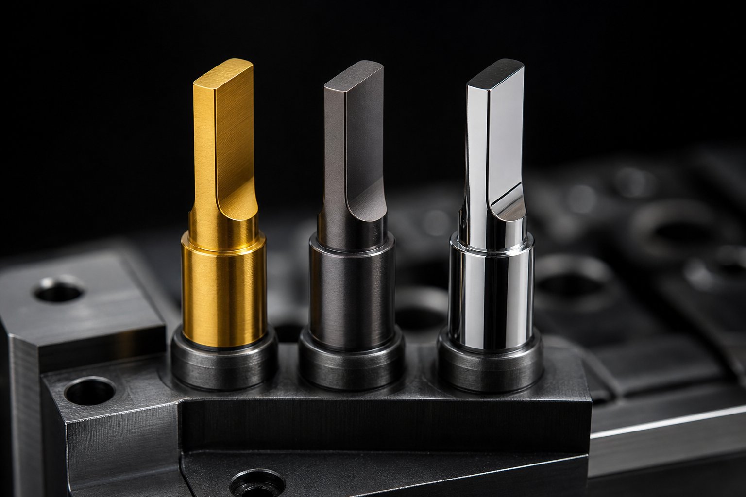
Even the best tool steel benefits from surface treatments that address the specific wear mechanism attacking the die. Stamping die coating options for wear resistance have expanded significantly, each targeting a different failure mode:
- TiN (Titanium Nitride): A general-purpose PVD coating that increases surface hardness and reduces friction. It provides moderate improvement against abrasive wear and is cost-effective for standard applications, though it is outperformed by newer coatings in demanding environments.
- TiCN (Titanium Carbonitride): Harder than TiN with better abrasive wear resistance. TiCN performs well against materials that generate high sliding friction, making it suitable for forming operations on harder sheet metals.
- TiAlN (Titanium Aluminum Nitride): Excels in applications where adhesive wear and galling are the primary failure modes. A study published in Micromachines demonstrated that TiAlN-coated AISI D2 stamping dies achieved an estimated lifetime gain exceeding 500% compared to uncoated tools, extending reconditioning intervals from 80,000 cycles to a projected 500,000 cycles. The coating also reduced the friction coefficient to 0.18, significantly lower than the 0.74 recorded for uncoated steel-on-tinplate contact.
- DLC (Diamond-Like Carbon): Extremely low friction coefficient (often below 0.15) and excellent resistance to adhesive wear. DLC coatings are particularly effective for stamping aluminum, copper, and other soft metals prone to galling on uncoated tool surfaces.
- Nitriding: A diffusion treatment rather than a deposited coating, nitriding creates a hardened surface layer that penetrates into the steel substrate. It improves fatigue resistance and provides moderate wear protection without adding a separate film that could delaminate under extreme impact.
Understanding how to extend stamping die life with coatings starts with diagnosing the failure mode. Abrasive wear calls for TiCN or TiAlN. Adhesive wear and galling respond to DLC or TiAlN. Fatigue-related surface cracking benefits from nitriding. Applying the wrong coating to the wrong problem wastes money without extending die life.
Matching Die Materials to Workpiece Properties
The workpiece itself constrains your material options. A die stamping soft copper foil faces entirely different demands than one cutting high-strength stainless steel. Tensile strength, surface hardness, ductility, and material thickness all influence which tool steel grade and coating combination will deliver acceptable life.
Harder workpiece materials generate more abrasive wear on cutting edges, demanding higher-carbide steels. Softer, more ductile materials tend to cause adhesive wear and material transfer (galling), where workpiece material bonds to the die surface. Thicker stock increases compressive loading on punches, favoring grades with higher deformation resistance.
| Tool Steel Grade | Working Hardness | Recommended Workpiece Materials | Expected Die Life Range | Typical Applications |
|---|---|---|---|---|
| AISI D2 | 58-60 HRC | Carbon steel, stainless steel, spring steel | 500,000-2,000,000+ strokes | High-volume blanking, long-run cutting operations |
| AISI A2 | 58-62 HRC | Mixed materials, medium-hardness alloys | 300,000-1,000,000 strokes | Progressive dies with multiple operation types |
| AISI M2 | 60-65 HRC | High-strength steel, abrasive alloys | 500,000-1,500,000 strokes | High-load punches, high-speed blanking |
| AISI S7 | 56-58 HRC | Heavy-gauge steel, thick stock | 200,000-800,000 strokes | Impact-prone stations, heavy-gauge stamping |
| Powder Metallurgy (CPM 10V) | 60-63 HRC | Abrasive materials, high-silicon steels | 2,000,000-5,000,000+ strokes | Ultra-high-volume production, abrasive workpieces |
| Tungsten Carbide | 85-92 HRA | All sheet metals, especially abrasive alloys | 5,000,000-10,000,000+ strokes | Cutting inserts for extreme-volume applications |
The relationship between die material, coating, and workpiece is not a lookup table you apply blindly. It is a set of engineering tradeoffs. A tougher steel with a hard coating can sometimes outperform a harder steel without one, because the coating handles the wear while the substrate absorbs the impact. Getting this combination right is what separates dies that run for years from dies that fail in months, and it is also what makes the press and guidance subsystems so critical. Even the best material pairing underperforms if the press delivers inconsistent force or the guidance system allows positional drift.
Press Selection and Die Subsystems for Achieving Tight Tolerances
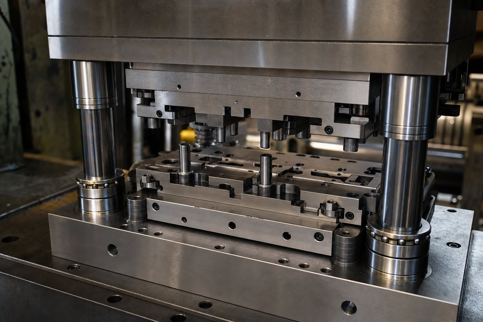
A precision die can only deliver what the press beneath it allows. Imagine installing a surgical instrument into a jackhammer: the tool's engineering becomes irrelevant if the machine delivering force cannot control velocity, position, and load with matching refinement. Press type selection for tight tolerance stamping is not an afterthought. It is a constraint that defines the ceiling of achievable accuracy, regardless of how well the die itself is built.
Mechanical, Hydraulic, and Servo Press Capabilities
Each press architecture imposes different limits on how precisely force reaches the workpiece. Understanding those limits helps you match press capability to die requirements rather than discovering mismatches during production.
Mechanical presses drive the slide through a crankshaft or eccentric gear mechanism, producing a fixed stroke profile determined by the flywheel's rotational energy. They excel at speed and consistency: once set up, they deliver the same stroke motion cycle after cycle with minimal variation. For high-speed progressive die operations where blanking and piercing dominate, mechanical presses offer excellent repeatability. Their limitation is rigidity in the motion profile. The slide velocity at bottom dead center (BDC) is dictated by geometry, not programming. In forming operations where material needs time to flow, that fixed velocity can create snap-through shock, reverse tonnage spikes that stress both die and press frame, and lateral punch deflection that degrades positional accuracy.
Hydraulic presses use fluid pressure to move the slide, providing full tonnage at any point in the stroke. This makes them ideal for deep drawing, where consistent force control throughout the forming depth is essential. They also allow dwell at BDC, giving material time to set a formed shape. The tradeoff is speed. Hydraulic systems cycle more slowly than mechanical presses and can introduce slight position variations from oil temperature changes and valve response lag, which limits their suitability for ultra-tight-tolerance, high-speed production.
Servo presses represent the most capable architecture for precision forming. A servo press for precision stamping replaces the flywheel and clutch with a direct-drive servomotor, giving the operator programmable control over slide velocity and dwell anywhere in the working part of the stroke. You can slow the slide to a crawl at the moment the punch contacts the workpiece, reducing snap-through shock and minimizing the lateral punch movement that causes misalignment. You can program a momentary dwell to set an emboss or profile. You can run in pendulum mode, where the slide oscillates through only the working portion of the stroke rather than completing a full 360-degree rotation, increasing production speed by 30% or more at the same motor RPM.
For precision stamping dies working advanced high-strength steels, this programmable motion is not optional. These materials require more forming energy and generate higher reverse loads. Controlling velocity right at the point of material contact minimizes friction buildup, reduces snap-through forces, and extends die life by limiting the lateral stress on punches. The result is tighter dimensional control on formed features and longer intervals between maintenance.
Die Guidance and Positioning Subsystems
The press delivers force. The die's internal subsystems control where that force lands. Even a perfectly tuned servo press cannot compensate for sloppy die guidance. As die design expert Art Hedrick notes, guide pins are intended to locate the upper and lower shoes precisely so that all die components interface with correct clearance, but they cannot fix a poorly maintained press. Both systems must function as the engineer intended.
Ball-bearing guide posts are the foundation of die pilot pin alignment accuracy. Unlike friction-style guide pins that ride on a thin oil film and generate heat at speed, ball-bearing posts use hardened steel balls in a precision cage to achieve what manufacturers call "negative slop": the pin-and-bearing assembly is approximately 0.0002 in. larger than the bushing bore, eliminating free play entirely. This zero-clearance fit ensures the upper and lower die halves return to exactly the same relative position on every stroke, even at high production speeds where friction pins would overheat and bind.
Pilot pins serve a different function. While guide posts align the die halves to each other, pilot pins align the strip material to the die. They enter pre-pierced holes in the strip before any forming or cutting occurs at that station, pulling the material into precise registration. In progressive dies running at hundreds of strokes per minute, even 0.02 mm of strip mislocation compounds across stations, producing out-of-tolerance parts. Pilot pins eliminate that drift by mechanically referencing the strip to the die geometry at every advance.
Stock lifters raise the strip between strokes so it can advance freely without dragging across die surfaces. This prevents strip distortion, slug pulling, and surface damage. Specialty stock lifter cylinders designed for progressive dies absorb side thrust and mount directly to stock rails, maintaining consistent lift height even under lateral loading.
Beneath these visible components, the elastic system quietly governs how forces distribute within the die. Springs, urethane pads, and nitrogen gas cylinders provide the counter-pressure that controls strippers, blank holders, and pad pressures. Improper spring selection is one of the most common sources of positional error in otherwise well-built dies. A stripper spring that is too weak allows the strip to lift unevenly, introducing tilt. A nitrogen spring system for stamping dies that is improperly charged delivers inconsistent blank holder force, causing metal flow variations that show up as dimensional scatter in formed parts. Nitrogen manifolds, which unify multiple cylinders through interconnecting gas channels, limit pressure rise to about 15% when fully compressed, providing more uniform and predictable force than individual springs.
Together, these components form a taxonomy of precision-maintaining subsystems. Each one addresses a specific source of positional error:
- Guidance system (ball-bearing guide posts, heel blocks, wear plates): Maintains alignment between upper and lower die halves within microns of travel, preventing lateral shift that would alter punch-to-die clearance.
- Positioning system (pilot pins, registration features, locating datums): Aligns the workpiece material to the die geometry at each station, ensuring that every operation references the same positional origin.
- Elastic system (springs, urethane, nitrogen cylinders, manifolds): Controls counter-pressure forces that hold, strip, and cushion material during forming, preventing uneven loading that introduces dimensional variation.
- Feed system (servo feeders, stock guides, feed length controls): Advances material in precise, repeatable increments matched to strip pitch, ensuring each station receives material at the correct position.
- Sensing system (in-die sensors, misfeed detectors, load monitors): Detects positional errors, material buckling, or abnormal forces in real time, stopping the press before a mislocation becomes a damaged die or a batch of scrap parts.
These subsystems do not operate in isolation. A feed error that the sensing system fails to catch becomes a positional error that the guidance system cannot correct. A worn nitrogen cylinder that the elastic system relies on introduces inconsistent pad pressure that shows up as dimensional scatter in the finished part. Precision is the product of all five subsystems functioning within their design intent simultaneously, stroke after stroke, across the entire production run.
This interdependence also explains why precision degrades over time. Wear, fatigue, and contamination gradually erode the performance of each subsystem, and the resulting quality loss is rarely sudden. It accumulates quietly until parts begin drifting out of tolerance. Recognizing those early warning signs, and knowing how to respond before precision is lost, is the difference between a die that delivers millions of good parts and one that generates escalating scrap.
Die Failure Modes and Maintenance That Preserves Precision
Precision does not vanish overnight. It erodes, one stroke at a time, through wear mechanisms that leave subtle fingerprints on part quality long before the die itself shows visible damage. A burr that grows 0.01 mm per ten thousand strokes. A formed dimension that drifts toward the lower control limit across a week of production. A surface scratch that appears on every fifth part. These signals tell you exactly what is happening inside your die, if you know how to read them.
Treating stamping die failure modes and causes as predictable engineering phenomena rather than random bad luck transforms maintenance from reactive repair into proactive lifecycle management. The goal is not just keeping the die running. It is preserving the micron-level accuracy you invested in during design and manufacture, across the die's entire productive life.
Common Failure Modes and Root Causes
Four primary failure mechanisms attack precision stamping dies during production. Each one follows a different physics, targets different die features, and leaves a distinct signature on the parts coming off the press. Recognizing which mechanism is active determines whether the correct response is sharpening, recoating, realignment, or replacement.
Chipping: Small fragments break away from cutting edges, typically at sharp corners, tight radii, or intricate punch profiles. The root cause is almost always an imbalance between hardness and toughness: die steel that is too brittle for the impact loads it experiences, or cutting edges subjected to lateral forces from misaligned stock. On parts, chipping shows up as irregular burrs that vary in height and location from stroke to stroke, unlike the uniform burr growth caused by simple edge wear. A diagnostic framework for die failures identifies chipping as one of the "Four Killers" of stamping dies, noting that the resulting edge appears jagged or saw-toothed under magnification.
Galling: When workpiece material microscopically welds to the die surface under pressure, then tears away on separation, it creates rough, smeared patches and built-up deposits on forming surfaces. Galling accelerates quickly because the transferred material increases friction, which generates more heat, which promotes more material transfer. On parts, galling produces scratches, score marks, and surface roughness that worsen progressively. It is most common when stamping stainless steel, aluminum, or other materials with a chemical affinity to tool steel, particularly when lubrication is inadequate or draw clearances are too tight.
Fatigue cracking: Repeated stress cycles eventually exceed the die steel's endurance limit, nucleating micro-cracks at high-stress features like radii, fillet transitions, and keyways. These cracks propagate slowly through the material until they reach critical length and cause a sudden fracture. The insidious aspect of fatigue is timing: a die might run flawlessly for 800,000 strokes before a crack that started at stroke 200,000 finally reaches a cutting edge. Part quality effects appear as intermittent dimensional variation, surface marks from crack-adjacent material flexing, or sudden catastrophic edge failure with no prior warning from gradual burr growth.
Misalignment-induced wear: When guide systems degrade, the upper and lower die halves no longer meet at exactly the same relative position on every stroke. Even 0.01 mm of lateral shift means the punch enters the die opening off-center, concentrating wear on one side of the cutting edge. This produces asymmetric burrs, one-sided edge rounding, and progressive dimensional drift in a single direction. It is the most common failure mode in dies with friction-style guide pins or in presses with worn gibs, and it often goes undetected because operators attribute the gradual quality shift to normal edge wear.
Preventive Maintenance Strategies
Effective preventive maintenance for stamping dies follows a structured rhythm that combines time-based inspection with production-based triggers. Relying on calendar intervals alone misses the reality that dies wear based on strokes, material hardness, and operating conditions, not days on the shelf.
Scheduled sharpening intervals: A stamping die sharpening schedule should be driven by actual stroke counts rather than arbitrary time periods. Industry practice ties sharpening review to documented hits-per-service intervals established from wear history. A production-based PM approach recommends using press counts for sharpening review, insert inspection, and selected replacement points. For precision dies, the trigger is typically set conservatively: sharpening occurs when burr height approaches 50-70% of the maximum allowable specification, not when parts have already drifted out of tolerance. All sharpening must be performed on a dedicated surface grinder with proper coolant and fixtures. Manual hand-grinding or improper grinding wheels are the leading causes of premature edge deterioration and heat damage to hardened surfaces.
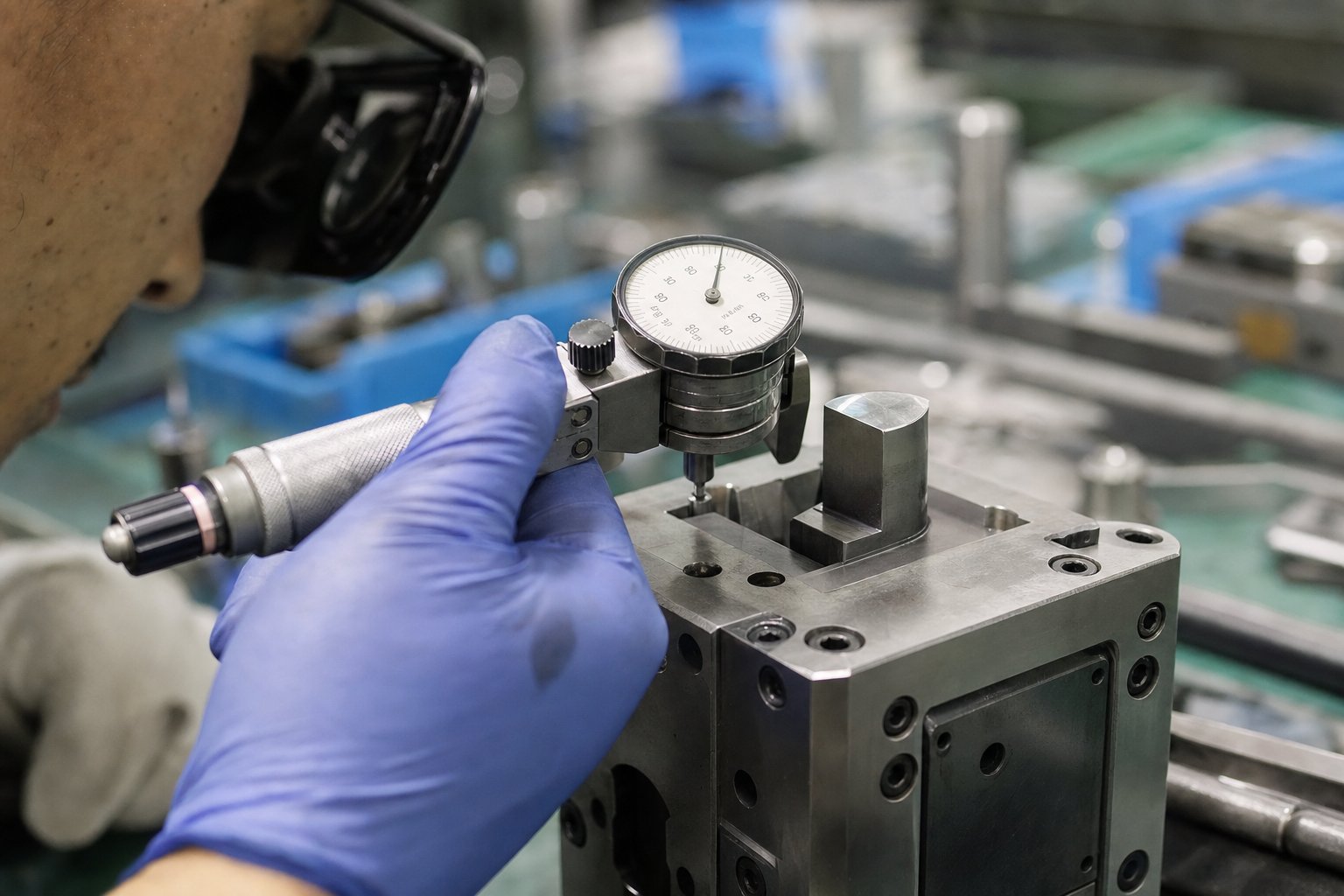
Inspection protocols for wear measurement: Quantitative inspection separates objective maintenance decisions from guesswork. Use micrometers and optical comparators to measure punch diameter reduction, die opening enlargement, and clearance changes at each PM interval. Feeler gauge clearance checks should verify that punch-to-die gap deviation does not exceed 0.02 mm from specification. Track these measurements over time. When plotted against stroke count, wear trends become predictable, allowing you to schedule maintenance during planned downtime rather than responding to quality alarms during production.
Condition-based maintenance using in-die sensors: Modern precision dies incorporate load sensors, proximity sensors, and misfeed detectors that provide real-time process data. When tonnage signatures shift, or when strip positioning sensors detect increasing variation, the die is communicating that something has changed. Condition-based maintenance responds to these signals rather than waiting for the next scheduled interval, catching problems like spring fatigue, guide wear, and progressive misalignment before they produce scrap. This approach bridges the gap between preventive and predictive maintenance, using actual die behavior rather than estimates to trigger service.
Research consistently shows that a fully reactive maintenance approach costs 25-30% more than a proactive, preventive strategy. The extra expense comes from paying two to three times more for emergency labor, 25-50% more for rush-ordered spare parts, and absorbing the far greater losses from interrupted production.
Die Refurbishment and End-of-Life Decisions
How to extend precision die life is ultimately a question of knowing when maintenance can restore original capability versus when the die has moved beyond recovery. That distinction determines whether you invest in refurbishment or begin sourcing replacement tooling.
When regrinding and recoating restore precision: If wear is limited to cutting edges and forming surfaces, and the die's structural geometry, guide systems, and mounting surfaces remain within specification, regrinding and recoating can return the tool to production-ready condition. Each regrind removes a small amount of material from the punch face, shortening the cutting length. Most precision dies are designed with a regrind allowance of 1-3 mm, providing multiple restoration cycles before the punch becomes too short to function. After regrinding, reapplying PVD coatings such as TiAlN or TiCN restores surface hardness and wear resistance.
When a die has reached dimensional limits: Regrinding cannot fix everything. If guide pin bores have worn oval, if die blocks have developed fatigue cracks in structural sections, or if cumulative regrinding has consumed the available allowance, the die has reached its end-of-life point. Continuing to run a die past this point produces parts that cannot reliably hold specification, generating scrap that costs more than replacement tooling.
The decision between refurbishment and replacement should follow evidence from maintenance records and process capability data, not intuition. When Cpk values trend below 1.33 despite verified maintenance, or when the interval between required service keeps shortening, the die is telling you it has entered its end-of-life phase.
Watch for these warning signs that a die is losing precision:
- Increasing burr heights: Burrs that grow back faster after each sharpening cycle indicate that regrinding is no longer fully restoring edge geometry, or that clearance has opened beyond the point where sharpening alone can compensate.
- Dimensional drift beyond Cpk thresholds: When process capability indices fall below 1.33 even after maintenance and setup verification, the die's mechanical condition can no longer support the required tolerance band.
- Inconsistent strip feed: Progressive roughening of die surfaces, worn pilot holes, or degraded guide systems create variable strip positioning that manifests as station-to-station dimensional scatter.
- Visible wear patterns on punch faces: Uneven wear, asymmetric polish marks, or witness lines on punch flats indicate misalignment or guide system degradation that cleaning and sharpening will not correct.
Documenting these observations at every maintenance interval creates the data trail that makes end-of-life decisions objective rather than emotional. A die that has served reliably for two million strokes deserves replacement with proper planning, not a crisis-driven scramble when it finally fails catastrophically during a production run.
Knowing when a die has reached its limits is one side of lifecycle management. The other side, equally important, is knowing where to source its replacement and how to evaluate whether a supplier can deliver the precision, consistency, and production support that the application demands.
How to Evaluate and Select a Precision Die Supplier
Replacing a worn die or launching a new stamped component puts you face-to-face with a sourcing decision that carries long-term consequences. A supplier that can hit your tolerance on a sample part is not the same as one that can hold it across a million-piece annual run while providing responsive support when something drifts. The gap between those two capabilities separates a transactional vendor from a genuine tooling partner, and bridging that gap requires a structured evaluation that goes well beyond requesting a quote.
Key Evaluation Criteria for Die Suppliers
When assembling your precision stamping die sourcing checklist, three categories of capability matter most: technical depth, quality systems, and production support infrastructure. Weakness in any one area eventually shows up as dimensional problems, delivery delays, or maintenance headaches downstream.
Technical capabilities define what a supplier can actually build. Look for specifics rather than generalities:
- Achievable tolerances: Ask for documented evidence of tolerances held in production, not just what the shop claims it can achieve on a single sample. A supplier targeting ±0.01 mm to ±0.05 mm should be able to show Cpk data from actual production runs, not just first-article measurements.
- In-house machining resources: Wire EDM, precision surface grinding, CNC jig boring, and optical profile grinding should all live under one roof. Outsourcing critical processes introduces handoff variation that precision work cannot absorb. Shops that maintain their own wire EDM and grinding departments retain tighter control over the iterative fit-and-check cycles that precision die assembly demands.
- Simulation tools: Forming simulation, springback prediction, and strip layout optimization software indicate a supplier that solves problems digitally before cutting steel. This capability directly reduces tryout iterations and compresses lead times.
Quality systems separate shops that inspect parts from shops that control processes. The distinction matters enormously for precision tooling:
- First article inspection (FAI): A rigorous FAI process verifies that the manufacturing process can consistently produce parts meeting all design requirements before full production begins. Look for suppliers that deliver complete FAI reports with dimensional data mapped to every critical feature, material certifications, and process documentation. This verification step catches dimensional, material, or process errors before they reach your production floor.
- Statistical Process Control (SPC): Suppliers running SPC on critical die dimensions during manufacture and during stamped part production demonstrate process awareness, not just inspection capability. Ask for sample control charts and Cpk documentation from comparable past projects.
- Certifications: ISO 9001 certification establishes baseline quality management discipline. For automotive applications, IATF 16949 is typically mandatory. These precision die maker quality certifications confirm that a supplier maintains documented systems for controlling processes, not just final inspection results.
Production support determines what happens after the die ships. Precision tooling is not a buy-and-forget asset:
- Tryout services: Can the supplier run production-representative tryouts on presses that match your tonnage, speed, and stroke profile? Tryout on an undersized or mismatched press masks problems that only appear in your production environment.
- Ongoing maintenance programs: Does the supplier offer scheduled maintenance, regrinding services, and emergency repair support? A supplier that builds the die and walks away leaves you carrying all lifecycle risk.
- Engineering responsiveness: When a die needs modification for a material change or an engineering revision, response time matters. Suppliers with dedicated die engineering staff adjust faster than shops where toolmakers double as designers.
Matching Supplier Capabilities to Project Requirements
Not every project needs the same supplier profile. The stamping die supplier evaluation criteria you prioritize should shift based on your specific application parameters. A large structural bracket stamped from mild steel at ±0.1 mm presents entirely different sourcing demands than a miniature electrical connector terminal held to ±0.02 mm across five million annual pieces.
Four project variables should drive your shortlist:
- Part size and geometry: Suppliers develop expertise around size ranges. A shop optimized for large automotive panels operates differently than one focused on small, intricate components. Matching your part envelope to the supplier's sweet spot ensures their equipment, fixturing, and inspection capabilities align naturally with your requirements.
- Tolerance band: Tighter tolerances demand suppliers with demonstrated process capability at that level, not just equipment theoretically capable of it. Request evidence from production runs, not prototypes.
- Annual volume: High-volume programs require suppliers with capacity planning discipline, backup tooling strategies, and the production infrastructure to sustain throughput without quality degradation over extended runs.
- Material type: Exotic alloys, advanced high-strength steels, or thin-gauge copper alloys each present unique forming challenges. Suppliers experienced with your specific workpiece material avoid the learning-curve failures that cost time and tooling.
For engineering teams sourcing tooling for small, high-accuracy, tolerance-critical parts, specialist suppliers often deliver better outcomes than generalist shops. Specialists in this space, such as YICHEN, focus their equipment, process development, and quality systems specifically on repeatable mass production of tight-tolerance components. That focused expertise translates into shorter development cycles, fewer tryout iterations, and more predictable production outcomes compared to shops that spread their attention across a wide range of part sizes and tolerance classes.
The evaluation sequence below provides a repeatable framework for moving from requirements definition to supplier selection:
- Define tolerance and volume requirements: Document the dimensional specifications, critical-to-quality features, annual volume, and expected die life before contacting any suppliers. Vague requirements produce vague quotes.
- Shortlist suppliers with demonstrated capability: Filter candidates based on documented evidence of achieving your tolerance band at comparable volumes. Eliminate suppliers who lack in-house wire EDM, grinding, or relevant simulation tools.
- Request first-article samples: Have shortlisted suppliers produce sample parts from production-intent tooling using your specified material. Evaluate dimensional conformance, edge quality, surface finish, and consistency across a sample batch, not just a single piece.
- Verify SPC documentation: Review process capability data from the sample run. Cpk values above 1.33 on critical dimensions indicate a process centered within its tolerance band with margin for normal variation. Values below 1.0 signal a process that cannot reliably hold specification.
- Assess ongoing support and maintenance terms: Confirm what happens after die delivery. Evaluate regrinding services, spare component availability, engineering change turnaround, and warranty terms. A lower die price from a supplier with no aftermarket support often costs more over the tooling's life.
This structured approach removes subjectivity from what is ultimately an engineering decision. Price matters, but it is one variable among many. The supplier who delivers the lowest quote but cannot demonstrate process capability, provide complete FAI documentation, or support the die through its production life is rarely the lowest-cost choice when measured across the full tooling lifecycle. How to select a precision stamping die supplier comes down to matching verified capability to documented requirements, then confirming that match with physical evidence before committing production volume.
Building Your Precision Stamping Die Strategy
Selecting the right supplier is the final link in a chain that starts much earlier. Every decision covered in this article, from die type selection to material specification to press matching, feeds into a single outcome: whether your stamped parts consistently meet specification at a cost that makes business sense. The engineering teams that get this right treat precision stamping dies as a system problem, not a component purchase.
Specification Mistakes to Avoid
Most costly errors happen before steel is ever cut. These common stamping die design mistakes quietly inflate budgets and compress die life without delivering any performance benefit:
- Over-tolerancing non-critical features: Every decimal point on a drawing carries a price. As industry engineers consistently observe, specifying ±0.02 mm on a feature that functions perfectly at ±0.1 mm forces tighter die clearances, harder tool steels, and more frequent sharpening, all without improving the product. Reserve tight tolerances for features that genuinely demand them.
- Under-specifying die materials for production volume: A die built from A2 when the run life demands D2 or powder metallurgy steel will wear prematurely, requiring early refurbishment that erodes the cost savings from cheaper tooling.
- Ignoring press compatibility: Designing a die without confirming press tonnage, shut height, bed area, and slide motion profile leads to tryout surprises that delay production and sometimes require die modification.
- Failing to plan maintenance from the design stage: Dies designed without regrind allowance, accessible wear components, or sensor mounting provisions force reactive maintenance that costs 25-30% more than a proactive approach.
Knowing how to reduce stamping die costs without losing precision starts here: spend engineering time at the drawing stage identifying which tolerances actually drive function, then match every downstream decision to those real requirements rather than arbitrary specifications.
Building a Precision Stamping Strategy
A stamping die strategy for engineering teams follows a logical sequence that aligns part requirements with tooling decisions:
- Start with part function. Identify which dimensions are critical to assembly, performance, or safety, and which allow standard tolerances.
- Select the die type that matches your geometry, volume, and tolerance profile: progressive for high-volume complexity, compound for flatness-critical parts, transfer for large or deep-drawn geometries.
- Specify die materials and coatings based on expected run life and workpiece properties, not just upfront cost.
- Match press capability to the die's forming requirements, particularly slide motion control for tight-tolerance forming operations.
- Establish maintenance protocols, sharpening intervals, inspection criteria, and end-of-life thresholds, before production begins rather than after problems appear.
Precision stamping die performance is a system outcome, not a component specification. No single element, whether material, coating, press, or maintenance schedule, delivers precision in isolation. It emerges from integrated decisions that reinforce each other across the entire tooling lifecycle.
Following precision stamping die specification best practices means accepting that each decision constrains the next. A tolerance target dictates material grade. Material grade influences coating selection. Coating performance depends on press dynamics. Press behavior determines maintenance frequency. Break any link and the system underperforms regardless of how well the other elements are engineered.
For engineering teams ready to move from research into active sourcing, particularly for small, tolerance-critical parts built for repeatable mass production, YICHEN's precision stamping die solutions offer a practical starting point for supplier conversations grounded in the evaluation framework outlined above.
Frequently Asked Questions About Precision Stamping Dies
1. What is the difference between a precision stamping die and a standard stamping die?
A precision stamping die targets tolerances from ±0.01 mm to ±0.05 mm with repeatability across millions of cycles, while standard dies operate at ±0.1 mm or looser. Precision dies require tighter punch-to-die clearances (3-5% of material thickness vs 8-12%), higher-grade tool steels like DC53 or SKD11, ball-bearing guide systems, and mirror-polished surfaces. The true differentiator is not the tolerance on the first part but the ability to maintain dimensional accuracy over the full production life of the tool.
2. How long do precision stamping dies last?
Die life depends on the tool steel grade, surface coatings, workpiece material, and maintenance discipline. AISI D2 dies typically achieve 500,000 to 2,000,000+ strokes for blanking operations. Powder metallurgy steels like CPM 10V extend life to 2,000,000-5,000,000+ strokes, while tungsten carbide inserts can reach 5,000,000-10,000,000+ strokes. Applying coatings such as TiAlN can extend reconditioning intervals by over 500%. Proper preventive maintenance, including scheduled sharpening and condition monitoring, is essential to reaching these figures consistently.
3. How do you choose between a progressive die and a transfer die?
The decision hinges on part size, geometry, and volume. Progressive dies excel for small to medium parts with moderate complexity at high volumes (100,000+ annually), using strip-fed multi-station sequencing to achieve tight tolerances efficiently. Transfer dies are necessary when parts are too large for strip feeding, require deep draws, or need to be rotated between stations. Transfer systems move individual blanks via gripper fingers, offering greater flexibility for complex 3D geometries but requiring more automation infrastructure.
4. What coatings work best for extending stamping die life?
The best coating depends on the dominant failure mode. TiAlN is highly effective against adhesive wear and galling, with studies showing lifetime gains exceeding 500% on D2 dies. DLC coatings provide extremely low friction (below 0.15) and prevent galling when stamping aluminum or copper. TiCN offers superior abrasive wear resistance for harder sheet metals. Nitriding improves fatigue resistance through a diffusion-hardened layer that resists surface cracking. Matching the coating to the specific wear mechanism is critical, as the wrong coating provides minimal benefit regardless of cost.
5. What should you look for when selecting a precision stamping die supplier?
Evaluate suppliers across three dimensions: technical capability (documented tolerances from production runs, in-house wire EDM and grinding, simulation software), quality systems (first-article inspection with complete dimensional mapping, SPC data with Cpk above 1.33, ISO 9001 or IATF 16949 certification), and production support (tryout on representative presses, maintenance programs, engineering change responsiveness). For small, tolerance-critical parts, specialists like YICHEN focus specifically on repeatable mass production tooling, offering focused expertise that generalist shops may lack. Always verify capability with physical samples before committing volume.


