


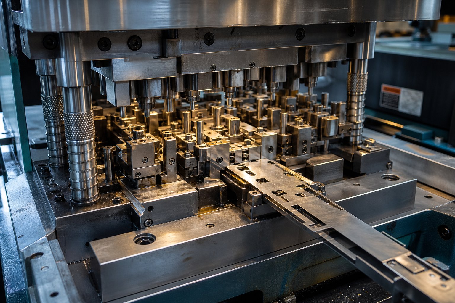
What Progressive Stamping Die Engineering Actually Involves
When someone asks "what is a progressive die," the typical answer describes a multi-station tool that stamps parts from a metal strip. That description is accurate but incomplete. It tells you what happens inside the press without addressing the engineering discipline that makes it all work reliably at speed, stroke after stroke, for millions of cycles.
Progressive stamping die engineering is the practice of designing integrated tooling systems where every press stroke advances a continuous metal strip through a planned sequence of piercing, forming, coining, and cutoff operations. Each station performs a discrete task, and the finished part drops out at the final station. Simple enough in concept. In execution, it demands decisions that cascade through every element of the die.
Defining Progressive Stamping Die Engineering Beyond the Basics
What separates this discipline from a basic process overview? Scope. A progressive die engineer doesn't just select operations - they determine how many stations are needed, where idle stations belong, how forming forces distribute across the press bed, and how strip layout geometry balances material utilization against carrier rigidity. They specify punch-to-die clearances based on material behavior, design pilot systems that maintain micron-level registration, and architect the die so it can be maintained without pulling it from the press.
Among all types of stamping dies - compound, transfer, single-hit - progressive dies carry the highest engineering density per square meter of tool steel. Every decision at one station affects what's possible downstream. That interconnected logic is what makes progressive die stamping both powerful and unforgiving.
Why Engineers Search for Progressive Die Design Content
Most online content about progressive stamping stays at the awareness level: process animations, general descriptions, lists of industries served. Engineers and toolmakers need something different. They need references that address station sequencing rationale, material-driven clearance decisions, strip registration mechanics, and die life planning.
Progressive stamping die engineering is the systematic design of multi-station tooling that transforms flat strip stock into finished components through sequenced operations - integrating station logic, force distribution, material behavior, and maintenance architecture into a unified system.
This article is written for that audience: engineers specifying progressive dies, toolmakers building them, and technical managers evaluating suppliers. The focus throughout is engineering logic - the reasoning behind design choices that determine whether a progressive stamping die survives a million-hit production run or fails well short of it.
Station Sequencing Logic That Drives Die Architecture
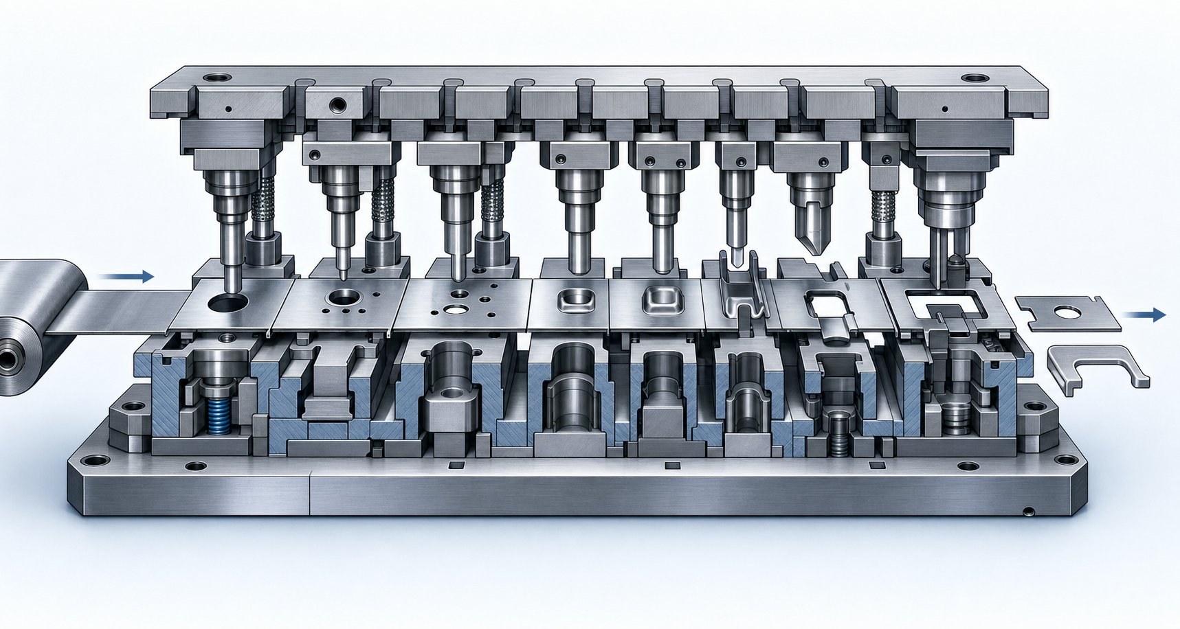
Station sequencing is where progressive stamping die design becomes an intellectual exercise rather than a mechanical one. The order in which operations happen across a die's stations isn't arbitrary - it's governed by material physics, registration requirements, and force distribution constraints. Get the sequence wrong, and you'll fight quality issues for the life of the tool.
Think of it this way: every station in a progressive die stamping process inherits the condition of the strip from the station before it. Deform the strip too early, and downstream operations lose their reference geometry. Concentrate cutting forces on one side of the die, and the press ram tips, accelerating wear unevenly. Sequencing decisions compound across the entire strip progression.
Why Piercing Precedes Forming in Most Progressive Layouts
In nearly every progressive die tooling layout, piercing operations happen before forming operations. The reason is registration. Pilot holes pierced in the first or second station become the datum features that locate the strip at every subsequent station. Pilot pins engage these holes before each stroke, correcting for feed tolerance, strip camber, and thermal growth.
If forming preceded piercing, the strip would already be deformed by the time you tried to establish datum references. Deformed material shifts unpredictably - it stretches, thins, and springs back. Piercing into a flat, undeformed strip gives you clean, dimensionally stable reference points that maintain registration accuracy throughout the entire progressive stamping process.
Beyond pilots, other pierced features - slots, locating edges, relief cuts - also benefit from being created while the material is still in its flat, work-hardened-free state. The general best practice is to create pilot and datum features early, distribute heavy cutting loads, and perform three-dimensional forming only after the strip has enough support from established references.
Balancing Forces Across Stations to Protect Press and Die
Imagine an eight-station progressive die where stations 1 through 4 perform all the heavy blanking and piercing on the left side, while stations 5 through 8 handle light forming on the right. The result? A significant tipping moment on the press ram. The load center doesn't align with the ram center, and the press deflects unevenly.
This is a real and measurable problem. Engineers calculate tipping moments by multiplying each station's force by its distance from the press ram centerline. MetalForming Magazine notes that die designers often overlook this step, centering the die in the press rather than centering the load - two very different things. The tell-tale signs of off-center loading include chipped punches, sheared die buttons, uneven cut bands, and accelerated maintenance cycles.
To manage this, engineers distribute blanking, piercing, forming, and trimming loads strategically across the die's footprint. Sometimes this means splitting a large blanking operation across two stations, or repositioning trim operations to counterbalance heavy forming forces on the opposite side. The goal is to keep the sum of tipping moments as close to zero as practical.
Station Count Considerations for Complex Geometries
How many stations does a part need? The answer depends on geometry complexity, tolerance requirements, and forming depth. A flat part with a few holes and a single bend might require four or five stations. A complex connector with multiple bends, embossed features, and tight positional tolerances could need 15 to 20 stations of stage tooling.
Idle stations - stations that perform no work on the strip - play a strategic role here. They provide physical space between operations that would otherwise interfere with each other. They also add strip stability in zones where forming forces could cause the carrier to buckle or twist. As The Fabricator points out, idle stations allow room for larger, stronger tooling sections and necessary die components that wouldn't fit if every station performed an operation.
More stations also mean a longer die, a wider press bed, and more material in the strip at any given moment. There's always a trade-off between process robustness and tooling cost. Engineers evaluate whether an additional station genuinely improves quality or simply adds complexity without benefit.
A typical sequencing logic flow for a progressive die follows this pattern:
- Pierce pilot holes to establish datum references
- Pierce additional holes, slots, and relief features in the flat strip
- Form primary bends and shapes using established datums for registration
- Coin or calibrate critical dimensions to final tolerance
- Trim excess material and perform final profiling
- Cut off the finished part from the carrier strip
Each step in this sequence relies on the one before it. Pilots locate the strip before piercing. Pierced relief features prevent tearing during forming. Forming establishes the geometry that coining refines. Trimming cleans up what forming distorted. And cutoff happens last because the carrier strip must hold the part stable through every preceding operation.
The sequencing logic reveals something fundamental about progressive die engineering: it's not just about what operations you need - it's about what condition the strip must be in when each operation happens. That condition depends heavily on how the workpiece material behaves under stress, which introduces an entirely different set of engineering variables.
Material Behavior and Its Impact on Die Design Decisions
Every sequencing decision, every clearance specification, every station count calculation ultimately traces back to one question: how does the workpiece material behave under load? Progressive metal stamping doesn't happen in the abstract - it happens to a specific alloy, at a specific thickness, with specific mechanical properties that dictate what the die can and cannot do at each station.
You'll notice that two parts with identical geometry but different materials can require completely different die architectures. One might run in eight stations; the other might need twelve. The reason lies in how each material responds to deformation, how it work-hardens, and how much it springs back when forming pressure releases.
How Tensile Strength and Elongation Shape Station Design
Higher-strength materials resist deformation more aggressively. That resistance means you can't push as much forming into a single station without risking tearing, thinning, or fracture. Engineers compensate by spreading the total deformation across more stations, each applying a smaller incremental change. A part that forms comfortably in two stations from low-carbon steel might need four or five stations in stainless steel.
Elongation - the material's willingness to stretch before fracturing - determines how aggressive each forming station can be. A material with 40% elongation allows deeper draws per station than one with 12% elongation. When elongation is low, engineers add relief stations and intermediate idle stations to let the strip stabilize between forming operations.
Work hardening compounds the challenge. Austenitic stainless steels, for instance, harden rapidly during forming. As MetalForming Magazine notes, forming stainless steels requires roughly twice the press power of mild steel due to their high work-hardening rate - and blankholder pressures for austenitic grades can reach three times what low-carbon steel demands. In progressive stamping materials with extreme work-hardening behavior, engineers must evaluate whether intermediate annealing is practical or whether additional relief stations can distribute the strain sufficiently.
Die Clearance Specifications by Material Type
Punch-to-die clearance is not a universal number you apply across all materials. It's a function of material thickness, tensile strength, and the edge quality you need. Get clearance wrong, and you'll see excessive burr, poor edge condition, accelerated punch wear, or slug pulling.
For carbon steel progressive stamping, the traditional rule of thumb is roughly 10% of material thickness per side. That works well for mild steel. But apply that same 10% to stainless steel, and you'll get the worst possible burr height - a reality that surprises toolmakers accustomed to carbon steel work. Materials with low yield-to-tensile ratios, including many advanced high-strength steels, need significantly greater clearance - research on AHSS grades shows that clearances up to 21% per side may be required for optimum edge-stretching ability.
Aluminum progressive stamping presents a different challenge. While aluminum is softer, its gummy nature causes adhesion on punch faces, and its lower shear strength means clearances must be tight enough to produce a clean shear band without excessive rollover. Progressive stamping copper and brass alloys respond differently again - their formability varies dramatically with alloy and temper, requiring clearance adjustments that account for specific material grades rather than broad category rules.
Grain Direction and Springback Compensation
Every rolled sheet has a grain direction - the orientation of its crystalline structure established during the rolling process. This direction directly affects where cracks form, how much force a bend requires, and how much the material springs back after forming.
Bending across the grain (bend line perpendicular to rolling direction) produces a stronger bend that tolerates tighter radii. Bending with the grain (bend line parallel to rolling direction) creates a weaker bend prone to cracking on the outside radius, especially at small radii. As The Fabricator explains, smaller-grained materials are less prone to grain separation and cracking, and maintain more consistent yield strength - making material quality a legitimate engineering specification, not just a procurement variable.
For progressive die engineers, grain direction must be specified at the design stage because it determines strip orientation on the coil. If critical bends need to run transverse to grain for crack resistance, the strip must be slit from the master coil in the correct orientation. This decision locks in before any steel is cut for the die.
Springback in progressive dies isn't a single-station problem - it's a cumulative one. Each forming station contributes angular deviation that compounds through subsequent stations. Simulation specialists at AutoForm emphasize that springback evolves as the sheet progresses through the lineup of forming and trimming stations, and compensation strategies must account for how each station's springback interacts with the next. Engineers overbend at forming stations to anticipate elastic recovery, but the correct overbend angle depends on material properties, bend radius, grain orientation, and what happens downstream.
| Material Type | Typical Clearance (% per side) | Forming Station Multiplier | Springback Tendency |
|---|---|---|---|
| Low-Carbon Steel | 8-10% | 1x (baseline) | Low to moderate |
| Stainless Steel (Austenitic) | 12-16% | 1.5-2x | High |
| Advanced High-Strength Steel | 15-21% | 1.5-2.5x | Very high |
| Aluminum (Automotive Grades) | 6-8% | 1.3-1.8x | Moderate to high |
| Copper / Brass Alloys | 5-8% | 0.8-1.2x | Low to moderate |
The table above illustrates why progressive die engineers can't design a single die architecture and swap materials freely. Each material type shifts the entire engineering equation - from how many stations you need, to what clearances you specify, to how aggressively you can overbend for springback compensation. These properties also determine which tool steels and surface treatments will survive the abrasive or adhesive wear each material inflicts on die components - a question that demands its own set of engineering decisions.
Tool Steel Selection and Heat Treatment for Progressive Dies
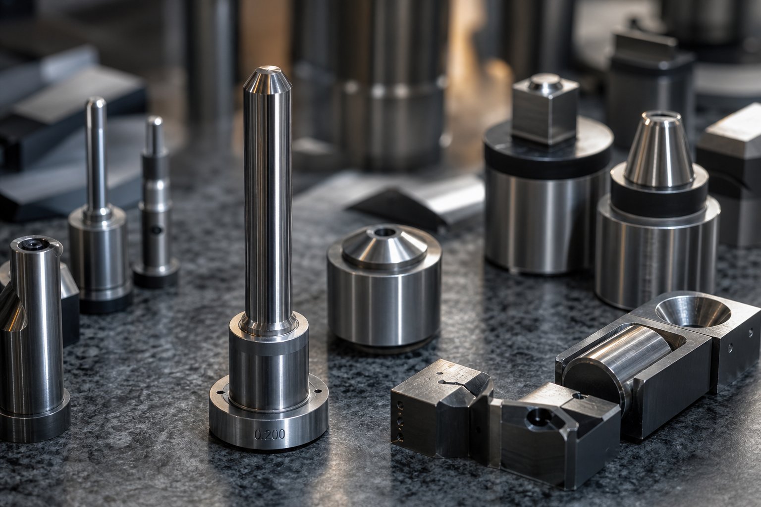
The workpiece material dictates forces and clearances. But those forces act on something - the tooling punches, die inserts, and forming sections that make contact with the strip millions of times. What those components are made of, and how they're heat-treated, determines whether a stamping die delivers consistent parts for a full production campaign or degrades unpredictably after a fraction of its intended life.
Sounds like a straightforward material-to-material matching problem? It's not. Different stations within the same progressive tool and die experience entirely different failure mechanisms. A piercing punch endures abrasive shearing. A forming insert absorbs repeated impact loads. A drawing station fights adhesive galling. Specifying one steel grade across the entire die - a practice some shops still default to - ignores these differences and guarantees that some stations are overbuilt while others are under-specified.
Tool Steel Grades for Punches Versus Die Blocks
Each station in a progressive die faces a dominant wear mechanism, and understanding which one governs failure is the first step in selecting the right grade.
Piercing and blanking stations experience abrasive wear - the cutting edge grinds against the workpiece material with every stroke, gradually losing its profile. For these metal punching tools, wear resistance is the priority. Forming stations, by contrast, see impact loading and fatigue - the steel must absorb cyclical shock without cracking. Drawing and coining stations often deal with adhesive wear (galling), where workpiece material transfers onto the tool surface and builds up over time.
These different demands map to different tool steel categories:
Air-hardening steels (A2, D2): The general-purpose workhorses. A2 offers a good balance of wear resistance and toughness, making it a solid all-around choice for moderate production runs. D2 steps up wear resistance significantly but trades away toughness - it can chip in stations subject to heavy impact or when cutting high-strength materials. As MetalForming Magazine notes, D2 is more brittle and can chip in aggressive forming applications.
High-speed steels (M2, M4, SKH9): When abrasion resistance must go further without stepping into carbide, high-speed steels bridge the gap. Their vanadium and tungsten carbide content resists edge degradation at the high temperatures generated during stamping. M4 in particular has gained favor for tooling punches in progressive dies running stainless steel or AHSS - materials that rapidly destroy conventional tool steel edges. For core punches and inserts, high-speed steels heat-treated to HRC 60-62 maintain edge integrity through millions of high-speed production cycles.
Powdered-metal (PM) steels (CPM 10V, CPM 3V): These offer the best combination of wear resistance and usable toughness for high-volume stamping dies. CPM 10V delivers outstanding edge retention in piercing operations, while CPM 3V emphasizes impact resistance for forming stations. The finer, more uniform carbide distribution in PM steels means they resist chipping better than conventional steels of comparable hardness.
Carbide inserts: For the most demanding applications - very high hit counts, extremely abrasive workpiece materials, or burr-critical features - tungsten carbide inserts provide wear life that no tool steel can match. The trade-off is brittleness, cost, and machining difficulty. Carbide works best in stations with pure compressive loading and minimal lateral forces.
The trend in progressive die engineering has moved decisively toward mixed-material construction. As one experienced toolroom manager put it: "Gone are the days of running one tool steel across the whole die." Modern stamping dies use M4 for cutting punches, A2 or S7 for die blocks, S7 for forming stations where fracture risk is highest, and carbide where burr control outweighs cost considerations.
Heat Treatment and Surface Engineering for Die Longevity
Selecting the right steel grade is only half the equation. How that steel is heat-treated determines where it falls on the hardness-versus-toughness spectrum - and getting this balance wrong creates predictable failures.
Imagine a piercing punch hardened to HRC 64 for maximum edge retention. It holds a sharp edge beautifully - until it encounters a slug that doesn't clear cleanly or a strip misalignment that creates a lateral load. The punch chips because it lacks the toughness to absorb unexpected stress. Conversely, a forming insert left at HRC 56 for toughness may survive impact loads indefinitely but "mushrooms" - its working surfaces deform plastically under repeated compression, drifting out of tolerance.
Experienced die engineers target hardness ranges based on station function: piercing punches typically run HRC 60-62, forming inserts HRC 58-60, and structural support plates HRC 58-60 for rigidity. These aren't arbitrary numbers - they represent the point where each component's primary failure mode is held in check without inviting its secondary failure mode.
Surface treatments add another engineering layer, but they're decisions tied to specific material and volume requirements - not universal solutions applied to everything:
Nitriding diffuses nitrogen into the tool surface to create a hardened case. It's applied at relatively low temperatures (800-1000 degrees F for plasma nitriding) and doesn't change tool dimensions significantly. The Fabricator identifies nitriding as a practical choice for stampers needing moderate protection in lower-volume applications without the complexity of more advanced processes.
PVD coatings (TiN, TiCN, AlTiN, CrN) deposit thin, hard layers at temperatures below 1000 degrees F - low enough that the base tool steel doesn't soften or change dimensions during application. PVD coatings excel at reducing friction and resisting adhesive wear, making them valuable for forming stations that fight galling. Because they don't alter tool dimensions, they're also practical for tight-tolerance cutting punches where post-coating grinding isn't feasible.
Thermal diffusion (TD) process creates a vanadium carbide layer at approximately 1800 degrees F - extremely hard and wear-resistant, but the high temperature changes the tool's crystal structure and dimensions. Engineers must design for post-treatment dimensional changes, and as coating specialists note, the process can induce cracking in vulnerable areas with sharp features or stress concentrations. TD coating works best for tools with robust geometries running very high volumes where dimensional compensation is planned into the original design.
The engineering decision tree for surface treatment follows the same logic as base material selection: what wear mechanism dominates, what volume justifies the cost, and what dimensional constraints exist?
- Expected hit count: Low-volume runs (under 100k) rarely justify PM steels or advanced coatings. High-volume campaigns (1M+) demand them for predictable maintenance intervals.
- Workpiece material abrasiveness: Stainless steel and AHSS destroy edges faster than mild steel - requiring harder steels or coated surfaces to maintain acceptable sharpening intervals.
- Station operation type: Cutting stations prioritize wear resistance. Forming stations prioritize toughness and galling resistance. Each demands different steel and treatment combinations.
- Maintenance interval targets: If the production schedule allows die pulls every 50,000 strokes for sharpening, moderate steels suffice. If the target is 200,000+ strokes between maintenance, PM steels with PVD coatings become necessary.
- Budget constraints: PM steels and carbide inserts cost more upfront, but lifecycle cost - including sharpening frequency, press downtime, scrap rates, and replacement parts - often favors the higher-grade material.
The cost calculation is worth reframing: it's not what the steel costs at purchase, it's what it delivers across the full production campaign. A CPM 10V punch that doubles tool life between sharpenings and eliminates unplanned press stops will outperform a D2 punch that costs a third as much but requires twice the maintenance attention. That lifecycle perspective is exactly what separates a well-engineered stamping die from one that merely gets built - and it's the same thinking that drives how modern simulation tools validate these material decisions before any steel is ordered.
CAD/CAM Simulation and Modern Progressive Die Design Workflows
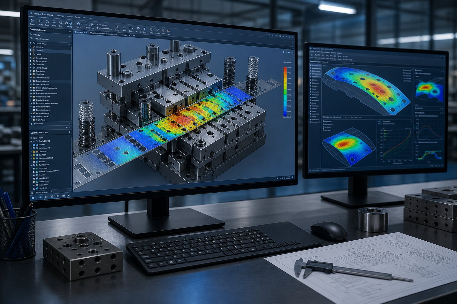
Selecting the right tool steels and coatings is a critical decision - but how do you validate that those choices will perform as expected before committing hundreds of thousands of dollars to machined steel? You don't build a die and hope. You simulate it. Modern progressive tooling development has shifted the heaviest engineering work from the tryout press to the computer screen, where forming analysis, springback prediction, and strip progression logic can be tested iteratively at a fraction of the cost and time.
This shift isn't a luxury for large OEMs only. Progressive die engineers at shops of all sizes now use simulation-driven workflows that catch problems months before a die stamping machine ever cycles. The result? Fewer tryout iterations, less rework, and dies that hit production targets faster.
FEA-Driven Forming Analysis and Strip Layout Simulation
Finite element analysis lets engineers subject a virtual strip to the exact forming conditions it will encounter in a progressive die press - station by station, stroke by stroke. The software discretizes the sheet metal into thousands of elements, applies the defined material properties, and calculates how each element responds to the punch, die, and pad forces at every station.
What does this reveal? Material thinning zones where fractures would initiate. Wrinkling patterns where compressive stresses buckle the sheet. Splitting risks at tight radii or near pierced features. All visible before any steel is cut for the die.
Tools like Logopress ProgSim - which uses AutoForm solver technology - act as virtual tryout presses specifically customized for progressive die designers working with small to medium-sized stampings. The software recognizes cutting and forming punches directly from the strip layout, automatically adjusts pressure-pad forces when it detects wrinkling, and provides feedback on forming tonnage at each station. Setup and run time ranges from minutes for smaller dies to a few hours for larger, multi-station assemblies.
Strip layout simulation serves a parallel function: optimizing how parts nest within the coil width to maximize material utilization. Engineers can rotate blanks, adjust pitch, and evaluate different carrier configurations digitally. As Centerline Engineering reports, using simulation software for blank size estimation and nesting during the quoting phase saves material cost upfront - "gaining that little bit of extra material on the pitch is huge." For a progressive stamping press running millions of parts, even a 2-3% improvement in material utilization translates to significant savings over the production campaign.
Springback Prediction and Compensation in Digital Prototyping
Springback - the elastic recovery that distorts a formed part as soon as press force releases - is one of the hardest problems in progressive die engineering. It's not a single correction you apply once; it compounds across multiple forming stations, and the compensation required at station 6 depends on what happened at stations 3, 4, and 5.
Simulation changes the game here. Instead of building a die, discovering that flanges spring open by 4 degrees, grinding overbend into the tooling, re-running, and iterating physically, engineers can predict springback digitally and compensate before machining begins. Advanced software like AutoForm calculates the springback shape after each forming station and compensates in the opposite direction - often by more than the original springback amount, since the relationship is rarely 1:1.
The key factor driving springback severity is the combination of a material's yield strength and tensile strength. When those values are close together (for example, YS = 420 MPa, TS = 480 MPa), springback magnitude worsens dramatically. Complex 3D parts using high-strength materials can exhibit distortions exceeding 4 mm on flanges if left uncompensated. Digital prototyping lets engineers iterate on overbend angles, pad pressures, and form geometries across dozens of virtual trials in hours rather than weeks of physical tryout.
For a die stamping press running AHSS or stainless components, this capability isn't optional - it's essential. Physical trial-and-error with high-strength materials burns through tryout budgets and timelines at an alarming rate. Simulation collapses that cycle.
From Simulation to Wire EDM and CNC Machining
Validated forming simulations don't just inform decisions - they feed directly into machining programs. Modern CAD/CAM workflows create a parametric chain from the strip layout through individual punch and die insert models to the CNC toolpaths and wire EDM programs that produce those components. Change an overbend angle in simulation, and that change propagates through the punch geometry, the die opening profile, and the corresponding machining code.
This parametric linkage matters because progressive die development is never a single pass. Simulation reveals a thinning risk, the engineer adjusts a radius, re-runs analysis, confirms the fix, and updates the die model. In older workflows, each of those changes required manual updates across dozens of drawings and machining programs. In a parametric system, the update is automatic. As Metalstamp's die designers found, "going back and making a change to the 3D model changes everything - including whatever 2D drawings had been created." The tool and die makers produce the die exactly as designed, and it works - because the design was already validated virtually.
Servo press technology adds another simulation dimension. Unlike conventional mechanical presses with fixed stroke profiles, servo-driven progressive stamping presses allow programmable slide motion - variable speed, dwell at bottom dead center, reverse pulses for material release. Engineers can simulate how these custom motion profiles affect forming outcomes at the design stage, optimizing press kinematics before the die ever enters the press. The result is better material flow, reduced impact loading, and extended die life - advantages that only manifest when the press motion is considered as part of the die engineering system, not treated as a fixed constraint.
Simulation-driven design validation reduces tryout time by catching forming failures, springback deviations, and progression issues digitally - before any tool steel is machined - compressing what once required weeks of physical iteration into days of virtual analysis.
The progression from simulation to production represents a fundamental shift in how progressive dies reach the press. Virtual tryout doesn't replace physical tryout entirely - it eliminates the gross errors and narrows physical tryout to fine adjustments. Die designers like those at Centerline Engineering now use simulation "right from the get-go," starting at quoting and continuing through final validation. The die arrives at tryout already compensated for springback, already balanced for forming forces, and already optimized for material utilization.
Yet simulation only validates what the engineer designs into the tool. It can confirm that a forming station won't crack the material, but it can't tell you whether that forming station should exist in the first place - or whether the part geometry itself needs modification to be producible at volume. That judgment call belongs to the die engineer evaluating manufacturability, and it's a conversation that happens before simulation ever begins.
Design for Manufacturability from the Die Engineer's Perspective
When a part design lands on a die engineer's desk, the first question isn't "can we stamp this?" It's "can we stamp this reliably at 200 strokes per minute for a million hits without the tooling self-destructing?" That distinction is the heart of DFM for precision die stamping. Features that look fine on a CAD screen can translate into punches too slender to survive, clearances too tight to maintain, or forming operations that fight material physics at every stroke.
DFM feedback from a die engineer isn't pushback - it's the translation layer between part function and tooling reality. The earlier this conversation happens, the fewer compromises end up baked into the die.
Minimum Web Distances and Punch Strength Constraints
Imagine a part with two round holes spaced just 0.5 mm apart in 1.0 mm thick steel. The sheet metal punches required to pierce those holes would need a web of die steel between them that's thinner than the material itself. Under millions of cycles of compressive and lateral load, that web cracks. The punches deflect toward each other. Edge quality degrades, and maintenance intervals collapse.
This is why minimum web rules exist. The general DFM guideline specifies that the material web between two features - or between a feature and an edge - should be at least 1.0 to 2.0 times the material thickness. Below that threshold, you're asking the tooling to do something it can't sustain at production speed.
Punch cross-section follows the same logic. To hole punch sheet metal reliably, the punch must have enough cross-sectional area to resist the buckling force generated during shearing. A rule of thumb: minimum punch diameter should not be less than the material thickness for round holes in mild steel, and should increase for higher-strength materials. Slots and non-circular features are more constrained because their narrowest cross-section governs strength. When features fall below these thresholds, the die engineer evaluates splitting the operation across multiple stations - piercing part of the feature at one station and completing it at another - or requests a design modification.
Bend Relief Requirements and Draft Angle Considerations
Bends in progressive precision metal stampings don't happen in isolation. They interact with adjacent features, edges, and other bends. Without proper relief, material at the end of a bend line bunches, tears, or produces an unpredictable flange height. Bend relief - a small notch or cutout at each end of the bend line - gives the material room to deform without constraint.
Bend radii themselves must respect material limits. The internal bend radius should be at least 1.0 to 1.5 times the material thickness for most sheet metals. Go smaller, and you stress the outer fibers past their fracture limit - especially when bending parallel to the grain direction. As The Fabricator explains, longitudinal bending (with the grain) increases the required minimum inside radius significantly compared to transverse bending. For steel plate between 0.5 and 0.8 inches thick, the minimum radius can jump from 2.5T for transverse bends to 3.75T for longitudinal bends.
Die engineers evaluate these relationships against the part's tolerance callouts. A bend specified at 0.5T radius in a high-strength material bending with the grain isn't just aggressive - it's a tool-life problem. The die will crack the part intermittently, generating scrap that increases as the forming insert wears. The DFM response: request a larger radius, reorient the part relative to grain, or add a forming station that pre-scores the bend line.
Carrier Strip Design and Strip Utilization Optimization
The carrier strip - the material connecting individual part progressions as they move through the die - is scrap by definition. But it's engineered scrap. Its width, web connections, and progression pitch balance two competing goals: minimize wasted material and maintain enough strip rigidity to feed reliably at speed.
A solid carrier works for basic cutting and bending where the strip stays flat throughout. But parts involving deep forming, drawing, or embossing need a stretch web carrier that allows metal to flow freely without distorting the pitch between parts. The carrier must also resist the horizontal force of feeding - roughly 10% of total strip weight per progression - without buckling. Too narrow, and it folds during feeding. Too wide, and you waste material on every stroke across the entire production run.
For die cut metal parts at high volume, even small improvements in strip utilization compound dramatically. Engineers optimize pitch (the distance between part repetitions), evaluate whether parts can nest or rotate for tighter packing, and determine the minimum carrier width that maintains feeding stability. Every millimeter of unnecessary carrier width multiplied by millions of strokes represents real material cost.
The common DFM feedback die engineers provide when evaluating a new part design typically includes:
- Feature spacing adjustments - moving holes or cutouts apart to meet minimum web requirements and protect punch longevity
- Radius modifications - increasing bend radii to prevent cracking and reduce forming forces, especially where grain direction is unfavorable
- Tolerance relaxation requests - identifying dimensions where tighter-than-necessary callouts force additional coining or sizing stations that add die cost without functional benefit
- Grain direction specifications - defining strip orientation relative to critical bends to prevent cracking and reduce springback variability
- Relief feature additions - specifying bend reliefs, notch radii, and stress-relief slots that prevent tearing during high-speed forming
Each of these recommendations traces back to a specific tooling constraint: punch strength, die life, strip stability, or process repeatability. The die engineer's DFM review is ultimately a longevity assessment - what must change in the part design so the tooling can deliver consistent progressive precision metal stampings across the full intended production volume without degradation.
Even with perfect DFM, though, a progressive die only produces accurate parts if the strip arrives at each station in precisely the right position. That positional accuracy depends on a mechanical system so fundamental it's easy to underestimate: the pilot pins that re-register the strip at every single stroke.
Pilot Mechanics and Strip Progression Accuracy
A progressive die can have perfectly sequenced stations, ideal clearances, and optimized tool steels - and still produce scrap if the strip isn't positioned correctly at each stroke. Pilot pins are the mechanism that closes the accuracy loop. They re-register the strip at every station, compensating for the inherent imprecision of the stamping feed system, strip camber, thermal expansion, and cumulative progression error. In a prog die running at 300+ strokes per minute, pilots are the last line of positional defense before punches engage the material.
Strip registration sounds simple: the feed advances the strip one pitch, pilots enter holes, the strip is located. In practice, the tolerances involved are tight enough that small engineering missteps in pilot design or timing produce compounding errors across the entire die.
Pilot Diameter and Clearance Engineering for Registration Accuracy
Pilot pins don't just drop into holes. They actively correct strip position. The feed system advances the strip to approximately the right location - typically within a few thousandths of an inch - and the pilots do the fine positioning. This means pilot-to-hole clearance determines how much correction is available and how precisely the strip seats.
According to MetalForming Magazine, pilots are typically sized with 0.0005 to 0.001 inches of clearance to the pilot holes, depending on material type and thickness. That clearance range is deliberately tight - loose enough to allow the pilot to enter without forcing the strip, but snug enough that the strip can't shift once seated.
Nose geometry matters as much as diameter. The bullet-nose taper on a pilot pin serves two functions: it guides the strip laterally into true position as the press descends, and it enters the hole before the full locating diameter engages. This tapered entry means the pilot tip contacts the strip before the stamping die lifters fully release it - creating a brief overlap where the strip is supported by both the feed system and the pilot nose simultaneously.
Pilot length is a balancing act. Pilots must be long enough to enter the strip before other punches engage and before the stripper face contacts the lower die. But excessive length creates its own problem - an overly long pilot can bind in the hole or pull the strip upward during die opening. Engineers specify pilot length relative to the die's timing requirements: the pilot tip must enter the strip at the exact crank angle where feed release occurs, and the locating diameter must seat before any cutting or forming begins.
Common Registration Failures and Engineering Solutions
The most common registration failure in progressive dies has nothing to do with the pilots themselves - it's feed-roll lift timing. If the feed rolls still grip the strip when the pilot's locating diameter enters the hole, the feeder fights the pilots. The result: one-sided pilot wear, elongated pilot holes, audible snapping as pilots engage, and progression errors that worsen at higher speeds.
The correct timing sequence requires the feed to advance the strip, then the pilot tip to enter the hole, then the feed roll to lift (release the strip), and finally the pilot's full diameter to seat and locate the strip. For dies using stamping die lifters that raise the strip off the die surface, the timing window narrows further - the feed roll must remain open until lifters reach the top of their travel with pilots still engaged. As feed-timing specialists explain, incorrect roll closure can trap extra material between the die and feeder, pushing the strip forward when pilots disengage and creating excessively long progressions.
Pilot hole distortion during forming is a subtler problem. When a drawing or deep-forming operation pulls material inward, it displaces the carrier strip - and any pilot holes located near that forming zone distort along with it. As The Fabricator explains, drawing in a progressive die without a properly designed stretch web carrier causes pilot holes to move as material flows inward. The solution is carrier design that decouples pilot hole locations from forming zones - using flexible web features that absorb material flow without transmitting distortion to the registration features.
Slug pulling presents another real-world challenge. When a piercing punch retracts, vacuum or friction can pull the slug back up into the die opening. That slug interferes with the next strip advancement or, worse, sits beneath the strip at the next station - causing a raised impression, a misfeed, or a broken punch. Engineers address slug pulling through proper die clearance, positive slug ejection features, and ensuring that piercing clearance doesn't create the suction conditions that retain slugs.
Springback accumulation across multiple forming stations also affects registration indirectly. Each forming station introduces angular deviation that shifts the strip's neutral position slightly. By station 10 or 12 in a complex prog die, the cumulative shift can exceed the pilot's correction range if engineers haven't accounted for it. The design solution: place pilots strategically - after major forming operations where the strip has already sprung back - so they correct the strip's actual position rather than fighting against elastic recovery forces.
Registration accuracy at each station compounds across the entire strip progression. A 0.001-inch error at station 3 becomes a positional uncertainty that every downstream station inherits, amplifies, or must correct - making pilot engineering a system-level discipline that distinguishes progressive die design from single-station thinking.
Proper pilot engineering is ultimately a durability question as much as an accuracy question. Pilots that fight the strip wear faster. Misregistered strips stress punches unevenly. Elongated pilot holes degrade progressively until the die produces out-of-tolerance parts - sometimes gradually enough that the drift isn't caught until an SPC alarm triggers downstream. The precision built into pilot mechanics at the design stage directly determines how long the die maintains its quality window across a full production run - and how much maintenance intervention it needs along the way.
Die Life Management and Maintenance Engineering
Pilot accuracy keeps parts in tolerance. Tool steel selection keeps edges sharp. But neither matters if the die can't be maintained efficiently when those edges inevitably dull, when inserts wear past their limits, or when a punch chips at 2 a.m. on a Friday. Progressive stamping dies engineered for million-hit runs share a common trait: maintainability was designed in from day one, not bolted on after the first unplanned press stop.
Think about it this way - a die that produces perfect parts but requires eight hours of teardown for a routine sharpening isn't engineered for production. It's engineered for a showroom. Long run progressive stamping demands tooling architecture where wear components can be accessed, replaced, and restored without pulling the entire die from the press or disassembling stations that don't need attention.
Modular Insert Construction and Quick-Change Components
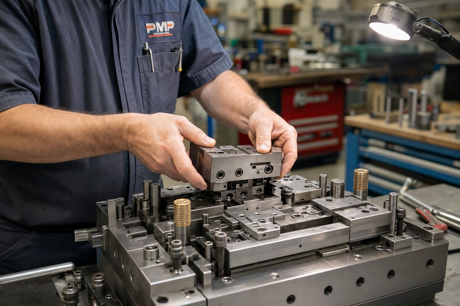
The shift from monolithic die blocks to sectioned insert construction is one of the most impactful developments in progressive die engineering over the past two decades. Instead of machining cutting profiles and forming geometries directly into a single massive die block, modern progressive stamping dies use individual inserts - replaceable die sections that bolt, pin, or wedge-lock into a common holder plate.
Why does this matter? Because wear doesn't happen uniformly across a progressive die. Station 3 might pierce through 0.8 mm stainless steel and need sharpening every 80,000 strokes. Station 7 might perform a gentle emboss in aluminum and run 500,000 strokes between service. With monolithic construction, servicing station 3 means pulling the entire die. With modular inserts, a technician removes that specific insert, sharpens or replaces it, and reinstalls - often without disturbing any adjacent stations.
As precision die manufacturers note, replaceable inserts provide faster maintenance, lower repair cost, improved wear localization, easier dimensional correction, and reduced downtime. Localized insert replacement becomes especially valuable in high-volume OEM production where specific stations experience concentrated wear loads that would otherwise force a complete die pull.
Quick-change punch retention systems extend this philosophy to the upper die half. Traditional punch retention relies on interference-fit mounting or through-bolt clamping that requires significant disassembly to access. Modern retention systems use keyed slots, bayonet-style locks, or wedge mechanisms that allow individual punches to be extracted and replaced from the top of the die without removing backup plates or disturbing neighboring punches. For high speed progressive die stamping running at 400+ strokes per minute, the difference between a 30-minute punch swap and a four-hour teardown is the difference between making schedule and missing a delivery window.
Sharpening Allowances and Expected Die Life Planning
Every cutting punch and die insert in a progressive die has a finite amount of material that can be removed through sharpening before the component falls below its functional length or depth. This isn't something engineers discover during production - it's designed in from the start.
Sharpening allowance refers to the total grind depth allocated to a punch or die section across its service life. A typical piercing punch might have 3-5 mm of sharpening allowance, with each regrind removing 0.05-0.15 mm depending on wear severity. That means 20 to 100 sharpenings over the component's life - and the expected hit count between sharpenings determines the die's total capacity before inserts need full replacement.
Engineers plan these intervals based on workpiece material, punch cross-section, and coating life. For stainless steel stamping at high speed, sharpening intervals might be 50,000-80,000 strokes for uncoated tool steel punches. With PVD-coated or carbide-tipped punches, that interval can stretch to 200,000+ strokes - but each regrind removes the coating layer, requiring recoating after sharpening if the full interval is to be maintained.
Waiting until visible burrs appear means tooling wear has already progressed too far. Research consistently shows that a fully reactive maintenance approach costs 25-30% more than a proactive, preventive strategy - the extra expense coming from emergency labor premiums, rush-ordered spare parts, and far greater production losses from interrupted runs. Precision manufacturers establish sharpening schedules based on actual stroke count rather than visual inspection alone, maintaining stable cutting loads and longer overall die life.
Common failure modes that drive unplanned maintenance include:
Chipping: Small brittle fragments break from cutting edges - typically caused by excessive hardness, impact loads exceeding the steel's toughness, or material fatigue at stress concentrations. Chipped edges produce irregular burrs and can damage the die opening below.
Galling: Workpiece material welds microscopically to the tool surface and builds up, creating rough patches that score subsequent parts. Forming stations working stainless steel or aluminum are particularly vulnerable when lubrication is inadequate.
Punch breakage: Catastrophic failure from lateral loading, slug pulling, strip misregistration, or fatigue accumulation past the steel's endurance limit. Broken punches can damage multiple adjacent components if fragments travel through the die.
Timing drift: Gradual wear in guide systems, cams, or lifters shifts the relative timing between upper and lower die components. The die still runs, but clearances shift, cut bands change, and forming depths vary - producing parts that slowly drift toward tolerance limits.
Partnering with Experienced Die Builders for Long-Run Production
Maintainability decisions made at the design stage depend entirely on production volume targets and the die builder's manufacturing philosophy. A die intended for 50,000 parts has fundamentally different maintenance architecture than one targeting 5 million parts. The million-hit die needs more sharpening allowance, more modular construction, better access for inspection, and components sized for multiple rebuild cycles.
Experienced progressive die stampings suppliers engineer these considerations into the tooling from inception - not because maintenance is glamorous, but because unplanned downtime at scale is devastatingly expensive. A supplier like YICHEN designs modular construction and sharpening allowances into progressive stamping dies specifically to support long-run production with minimal unplanned stops. Their approach reflects a broader industry truth: the die builder's experience with high-volume campaigns directly determines how well the tooling sustains itself across its full intended life.
What separates a die built for maintainability from one that merely functions? The engineering considerations that experienced builders evaluate include:
- Insert modularity: Individual station inserts sized for independent removal, with alignment features that guarantee repositioning accuracy after reinstallation
- Grind life allocation: Sufficient sharpening stock in all cutting components to support the full production volume, with punch lengths and die depths designed to accommodate cumulative material removal
- Inspection access points: Clearance for measuring tools and visual inspection at critical wear zones without requiring die disassembly - allowing in-press condition checks during scheduled production breaks
- Sensor integration for predictive maintenance: Provisions for load monitoring, misdetection sensors, and tonnage signature systems that detect wear progression before it causes part quality deviation
- Spare component standardization: Common insert geometries, punch diameters, and retention hardware across multiple stations where possible - reducing the inventory of spares needed and speeding replacement during maintenance windows
Sensor integration deserves particular attention. As IoT-enabled die monitoring evolves, sensors embedded in progressive dies track force, alignment, and temperature during operation. The data these sensors produce enables predictive maintenance - identifying wear trends and scheduling interventions before failures occur, rather than reacting after a broken punch damages the die or a dimensional drift contaminates a production lot.
The financial case for designing maintainability into progressive stamping dies is straightforward: every hour of unplanned downtime costs production revenue, generates scrap, disrupts schedules, and pulls engineering resources into crisis response. A die that's slightly more expensive upfront but runs 30% longer between maintenance events and sharpens in half the time delivers dramatically better total cost of ownership across a million-hit campaign.
Maintainability engineering is where die design meets production reality. But even the best-maintained die needs to come from a supplier with the engineering depth to get these decisions right in the first place - which raises the question of how production engineers and procurement teams should evaluate progressive die sources when reliability across millions of cycles is the non-negotiable requirement.
Sourcing Progressive Stamping Dies for Scalable Production
A die engineered for maintainability still needs a builder with the technical depth to execute that engineering correctly. When production engineers and procurement teams evaluate progressive die manufacturers, the decision isn't a simple vendor comparison - it's an assessment of whether a supplier's engineering ecosystem can deliver repeatable quality across the full production lifecycle. The cheapest quote rarely produces the lowest total cost.
What Production Engineers Should Evaluate in a Die Supplier
Imagine two quotes for the same progressive die metal stamping program. One comes in 20% lower. Both suppliers claim they can hold tolerance. How do you differentiate? You look past the price line and into the engineering infrastructure behind it.
In-house simulation capacity is the first indicator. A progressive die manufacturer running FEA-based forming analysis and strip layout simulation catches problems digitally - before they become expensive physical tryout iterations. Suppliers without simulation capability rely on trial-and-error at the press, which means your timeline absorbs their learning curve.
Tryout press tonnage and precision matter equally. A supplier validating your die on a worn press with poor BDC repeatability can't guarantee the die will perform identically on your production equipment. As stamping equipment specialists emphasize, a die validated on a precision press operates in a fundamentally different quality regime than one proven on aging conventional equipment.
Measurement and inspection capability - CMM verification, optical comparators, SPC documentation - determines whether the supplier can prove their die meets specification or merely claims it does. For demanding sectors like medical progressive stamping, where traceability and dimensional evidence are regulatory requirements, inspection infrastructure isn't optional.
Material sourcing transparency rounds out the evaluation. A progressive stamping company that specifies tool steel grades, heat treatment parameters, and coating processes in their documentation gives you visibility into what you're buying. Suppliers who treat these as proprietary details leave you unable to evaluate or replicate maintenance decisions downstream.
From Prototype to Scalable Mass Production
The die engineering lifecycle doesn't end when the last insert is ground to size. It extends through tryout validation, first-article qualification (PPAP or equivalent), production ramp-up support, and ongoing maintenance partnership. Suppliers who treat delivery as the finish line leave production engineers without technical backup when real-world issues surface at speed.
Progressive stamping and fabrication programs that span automotive, electronics, and appliance sectors increasingly require suppliers capable of supporting the full arc - from initial DFM collaboration through high-volume production monitoring. A progressive die and stamping partner engaged across this entire lifecycle catches issues earlier, resolves them faster, and reduces total cost of ownership compared to transactional vendor relationships where each phase involves a different team.
YICHEN exemplifies this lifecycle approach, supporting production engineers and procurement teams from design collaboration through scalable mass production - with particular focus on tight repeatability and the modular construction philosophy discussed in earlier sections. When evaluating any progressive die manufacturer, look for that same continuity of engineering involvement across phases.
| Supplier | Engineering Capability | Simulation Tools | Tryout Capacity | Production Monitoring Support | Maintenance Program |
|---|---|---|---|---|---|
| YICHEN | Full-service progressive die design for high-volume multi-station forming | CAD/CAM with forming analysis | In-house tryout and validation | Production ramp support and quality monitoring | Modular insert design with sharpening allowance planning |
| Typical mid-tier supplier | Standard die design, limited DFM feedback | CAD only, no FEA | Outsourced or limited press tonnage | Delivery-only relationship | Reactive maintenance, no designed-in modularity |
| Low-cost supplier | Build-to-print, minimal engineering input | None or basic 2D | Customer-supplied tryout | None | No planned maintenance architecture |
The table above isn't a ranking - it's a framework for understanding what you're actually buying at different price points. A progressive die manufacturers evaluation that ignores simulation capability, tryout infrastructure, and maintenance philosophy is really just a price comparison. And price comparisons on progressive tooling are misleading, because the die's upfront cost represents a fraction of its lifetime production impact.
When annual volumes reach hundreds of thousands or millions of parts, the engineering decisions embedded in your progressive die - station sequencing, material selection, pilot mechanics, maintainability architecture - either compound in your favor or compound against you. Every chapter of this article has addressed one piece of that compounding equation. The suppliers worth partnering with are those who understand all of them simultaneously, and who engineer progressive stamping dies that don't just run - they survive.
Frequently Asked Questions About Progressive Stamping Die Engineering
1. What is a progressive die and how does it differ from other stamping dies?
A progressive die is a multi-station tooling system where each press stroke advances a continuous metal strip through sequential operations - piercing, forming, coining, and cutoff - until a finished part drops at the final station. Unlike compound dies that perform multiple operations in a single stroke at one station, or transfer dies that move discrete blanks between stations, progressive dies maintain the workpiece on a carrier strip throughout the entire process. This interconnected strip progression demands engineering decisions about station sequencing, force distribution, and registration accuracy that compound across every station.
2. How many stations does a progressive die typically need?
Station count depends on part geometry complexity, tolerance requirements, and forming depth. A flat part with a few holes and one bend might need four to five stations, while a complex connector with multiple bends, embossed features, and tight positional tolerances could require 15 to 20 stations. Engineers also incorporate idle stations - stations performing no work - to provide physical space between interfering operations and add strip stability where forming forces could buckle the carrier. The trade-off is always between process robustness and tooling cost, as more stations mean a longer die, wider press bed, and higher upfront investment.
3. Why does material type change the entire progressive die design?
Material properties dictate station count, clearances, and forming strategies. Higher-strength materials like stainless steel require more forming stations with smaller incremental deformations because they resist deformation aggressively and work-harden rapidly. Die clearances vary dramatically - from 8-10% per side for mild steel to 15-21% for advanced high-strength steels. Springback tendency also shifts the overbend compensation needed at each forming station. Even tool steel selection and surface treatments must match the workpiece material's abrasiveness and adhesion characteristics. Two identical part geometries in different materials can require completely different die architectures.
4. How do engineers ensure strip registration accuracy across all stations in a progressive die?
Strip registration relies on pilot pins that re-locate the strip at every station before punches engage. Pilots are sized with 0.0005 to 0.001 inches of clearance to pilot holes pierced in the first stations. Their bullet-nose taper guides the strip into true position as the press descends, correcting for feed tolerance, strip camber, and thermal expansion. Critical engineering considerations include proper feed-roll lift timing so the feeder doesn't fight the pilots, strategic pilot placement away from forming zones to avoid hole distortion, and carrier strip design that decouples registration features from material flow during drawing operations.
5. What should production engineers look for when sourcing a progressive die supplier?
Evaluate suppliers on engineering infrastructure rather than price alone. Key criteria include in-house FEA simulation capacity for catching forming issues digitally, tryout press tonnage and precision that matches your production equipment, CMM and SPC measurement capability for dimensional verification, and material sourcing transparency documenting tool steel grades and heat treatment parameters. Full-lifecycle suppliers like YICHEN - who support from DFM collaboration through production ramp-up and maintenance planning - deliver lower total cost of ownership than transactional vendors where each project phase involves different teams. Modular insert construction and designed-in sharpening allowances are indicators of a supplier engineering for long-run reliability.


