


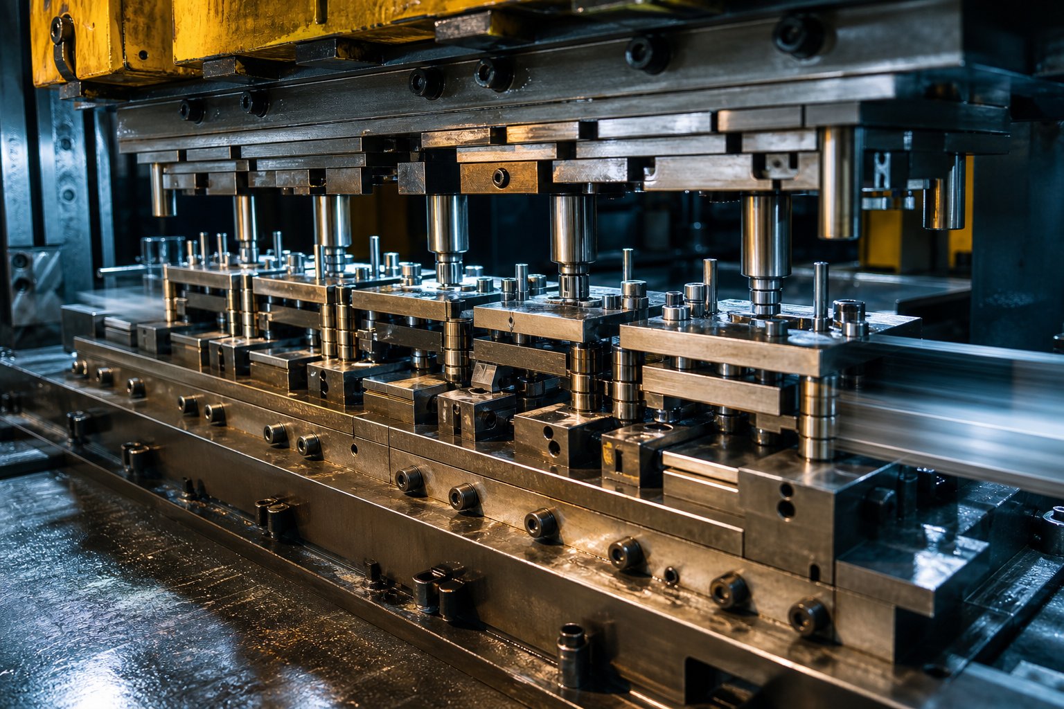
What Is Progressive Die Stamping and Why It Matters
Imagine producing a finished metal part with every single stroke of a press - no repositioning, no secondary setups, no operator intervention between steps. That's what the progressive die stamping process delivers, and it's been the backbone of high-volume metal component manufacturing since the mid-20th century.
Defining Progressive Die Stamping
Progressive die stamping is a coil-fed metalworking process in which a continuous strip of metal advances through multiple stations within a single die, with each station performing a distinct operation - blanking, piercing, bending, or forming - until the finished part separates at the final station.
So, what is a progressive die? It's a specialized tool containing a sequence of workstations, each designed to shape the metal strip incrementally. A coil of sheet metal feeds into the press, advances a fixed distance (called the pitch) with every stroke, and exits as a completed component. The strip stays connected throughout the process via carrier tabs, giving each station a stable reference point until the cutoff operation releases the part.
Whether you're an engineer specifying tolerances or a procurement lead comparing per-part costs, the core idea is the same: one tool, multiple operations, continuous output.
Why This Process Dominates High-Volume Production
Progressive metal stamping became the default for mass-produced parts because it solves three problems simultaneously:
- Speed - High-speed presses can run at 300+ strokes per minute, producing thousands of finished parts every hour.
- Repeatability - Pilot pins and fixed die geometry mean the millionth part is dimensionally identical to the first.
- Minimal handling - The strip carries itself through the die, eliminating manual loading between operations and the variation that comes with it.
These advantages compound at scale. Labor cost per part drops to fractions of a cent, tooling investment amortizes across millions of cycles, and scrap from operator error essentially disappears. For parts requiring multiple features - holes, bends, formed tabs - progressive die stamping consolidates what would otherwise be separate setups into a single uninterrupted cycle.
The real question isn't whether this process works. It's understanding exactly how each station contributes to the final part - and where smart design decisions translate into measurable cost savings.
How the Progressive Stamping Process Works Station by Station
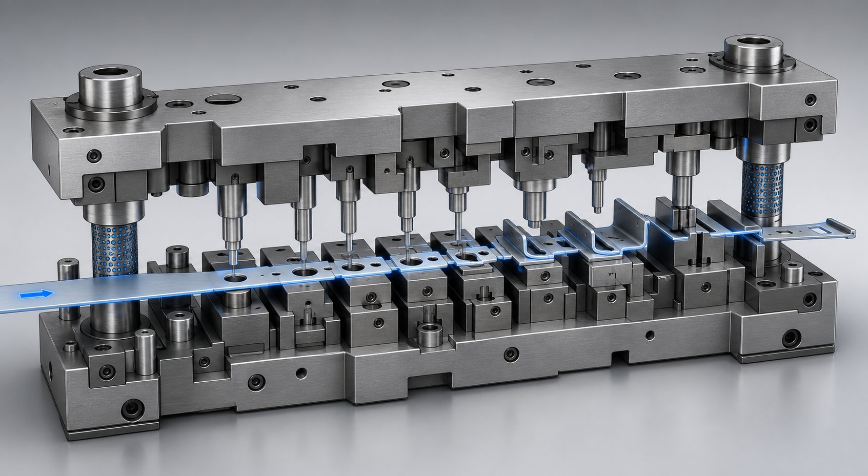
Picture an electrical connector bracket - a small part with pilot holes, a formed tab, and a precise cutout. It starts as a flat coil of copper alloy and exits the die as a finished component, all within a fraction of a second. Understanding how does a stamping press work at this level reveals why the die process demands such careful engineering at every station.
Strip Feeding and Pilot Registration
The coil stock enters the progressive stamping press through an automated stamping feed system - typically a roll feed or grip feed mechanism. Roll feeds use paired rollers that rotate a set distance per stroke to advance the strip by a precise pitch length. Grip feeds use a reciprocating clamp that grabs and pulls the strip forward, often preferred for thicker materials or longer feed lengths.
Pitch control is critical. According to Metal Forming Magazine, factors like strip-lifter travel and distance between feed unit and die can introduce pitch errors if feed-roll closure timing isn't calibrated correctly. Even fractions of a millimeter in misfeed translate into defective parts.
Once the strip reaches each station, conical pilot pins descend into pre-punched pilot holes to register the strip's exact position. This ensures alignment accuracy within ±0.001 inches (0.025 mm) - the kind of repeatability that keeps tolerances consistent across millions of cycles.
Sequence Logic Across Stations
Operations in a progressive stamping die aren't arranged arbitrarily. The sequence follows strict forming logic designed to protect part integrity:
- Pilot hole piercing - Created first to establish registration datums for all downstream stations.
- Feature piercing and punching - Holes and cutouts are formed while the strip is still flat, preventing distortion that would occur if punched after bending.
- Notching - Relief notches are cut before bends to eliminate stress concentrations and material interference at fold lines.
- Forming and bending - Tabs, flanges, and angles are shaped progressively, with simple forms preceding complex ones.
- Coining or embossing - Fine details and dimensional refinements are applied to already-formed geometry.
- Cutoff and separation - The finished part is sheared free from the carrier strip at the final station.
Why this order? Piercing before forming prevents hole distortion - a round hole punched into a flat strip stays round, but punching after a bend introduces stress that elongates it. Notching before bending relieves material that would otherwise buckle or crack at the fold. Throughout the progression, carrier tabs keep the strip connected, providing structural stability so each station has a rigid workpiece to act on.
A typical connector bracket might require 6 to 12 stations. High-speed progressive stamping presses running at 200 to 400+ strokes per minute can produce thousands of these parts hourly - each one identical to the last.
Final Separation and Part Ejection
At the last station, a cutoff punch severs the finished component from the carrier strip. The part drops through the die or is ejected by spring-loaded pins into a collection chute below the press. Meanwhile, the remaining skeleton strip - now just a ribbon of scrap - exits the die and winds onto a scrap reel for recycling.
The entire progressive stamping process, from coil entry to part ejection, happens in continuous motion. There's no pause between parts, no manual transfer, no re-fixturing. Each press stroke simultaneously advances every station, meaning six or more operations occur in parallel with every cycle.
This parallel efficiency is what makes the die process so productive at volume. But it also means the tooling itself - the punches, die blocks, strippers, and guides inside the die - must function as a tightly integrated system. How those components interact determines both part quality and die longevity.
Critical Die Components and How They Interact
A progressive stamping die might look like a solid block of steel from the outside, but crack it open and you'll find dozens of precision-ground stamping die parts working in concert. Each component has a single job, yet none can function without the others. Think of it as a mechanical orchestra - one out-of-tune section and the entire performance falls apart.
Punch Plates, Die Blocks, and Strippers
The punch plate sits in the upper half of the die and carries all cutting and forming punches. These punches - available in round, oblong, or custom profiles - descend into the strip material with every press stroke to pierce holes, shear profiles, or form geometry. Their shapes match the features required at each station.
Below the strip, die blocks provide the mating geometry. Each die block contains precision-machined openings (called die buttons) that correspond to the punches above. The clearance between punch and die button - typically 5-10% of material thickness per side - determines edge quality and tool life. Too tight and you overload the punch; too loose and burrs form on the part.
The stripper plate completes the trio. As Wisconsin Metal Parts explains, the stripper plate performs two critical jobs: it clamps the material flat against the die block during operations and strips the material off the punches on the return stroke. Without it, the strip would stick to the punches and pull upward, destroying the part and potentially damaging the die.
Pilots, Lifters, and Stock Guides
Pilots are bullet-nosed pins that descend into pre-pierced holes at each station. They provide final positional correction beyond what the feed mechanism alone can achieve - settling the strip into exact alignment every single stroke. This registration accuracy is what keeps hole locations, edges, and formed features within tolerance across millions of parts.
Stamping die lifters are spring-loaded pins or rails that raise the strip off the lower die surface after each stroke completes. By lifting the strip, they create clearance so the material can advance freely to the next station without dragging across forming surfaces or catching on die edges. This sounds simple, but improper lifter height or spring force causes misfeed errors that cascade through every downstream station.
Stock guides run along both sides of the strip, creating a channel that prevents lateral drift. They keep the coil material tracking straight through the die so that pilot pins can do their fine-tuning work without fighting gross misalignment.
How Components Work Together as a System
During the press stroke cycle, the upper die shoe descends, guided by precision guide pins and bushings (often ball-bearing type in high-speed progressive die tooling) that maintain alignment within tenths of a thousandth. The stripper contacts the strip first, clamping it flat. Punches then pass through the stripper to perform cutting or forming operations against the die blocks below. On the return stroke, the stripper holds the material down while punches retract cleanly. Lifters then raise the strip, the feed mechanism advances it one pitch, and the cycle repeats.
Every stamping die depends on this interaction being seamless. Roller bearing cages in the die set ensure the upper and lower shoes return to the same position cycle after cycle. Backing plates behind inserts prevent hardened tooling from being driven into softer die shoes under repeated impact. Heel blocks support punches that experience side-loading from single-sided cuts. It's an integrated system where each component protects the others.
| Component | Function | Typical Material |
|---|---|---|
| Punch plate | Holds and locates cutting/forming punches | A2 or D2 tool steel |
| Punches | Pierce, blank, or form the strip material | D2, M2, or tungsten carbide |
| Die blocks / die buttons | Provide mating cutting edge and forming cavity | D2 tool steel or carbide inserts |
| Stripper plate | Clamps strip flat; strips material from punches on return | A2 tool steel (hardened) |
| Pilot pins | Register strip position at each station | M2 high-speed steel |
| Lifters | Raise strip for smooth feed advancement | Case-hardened alloy steel |
| Stock guides | Prevent lateral strip drift | A2 tool steel or hardened alloy |
| Guide pins and bushings | Align upper and lower die halves precisely | Hardened tool steel / aluminum bronze bushings |
| Backing plates | Protect die shoes from punch impact forces | Hardened tool steel |
| Die shoes (upper/lower) | Structural foundation; mount all components | 1045 medium carbon steel or cast iron |
The material choices in this table aren't arbitrary. Higher-volume stamping dies use D2 or carbide inserts at cutting stations because those materials resist abrasive wear over millions of cycles. Lower-volume tools might use A2 steel - tougher and less prone to chipping, though it dulls faster. The decision always comes back to balancing tool life against upfront cost.
What matters most is how material selection and geometric precision combine across all these components. A perfectly ground punch paired with a worn die button still produces bad parts. A flawless die block paired with weak lifters still causes misfeeds. Progressive die tooling performance lives in the system, not in any single part - and understanding that system is what separates reliable production from chronic troubleshooting.
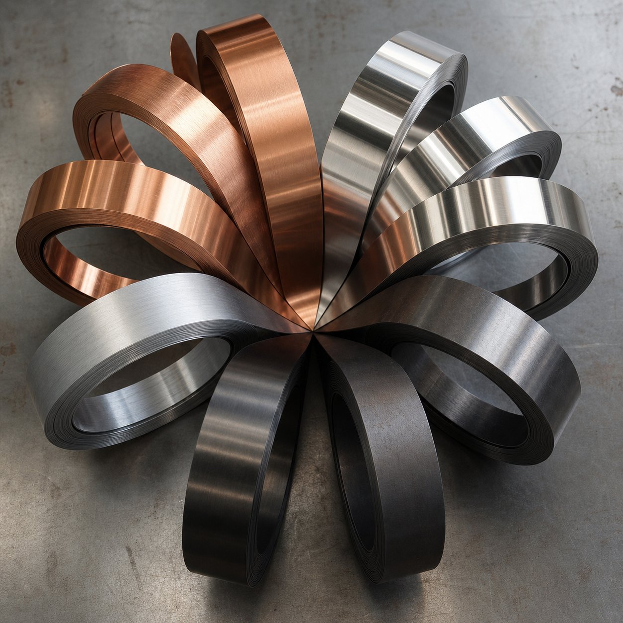
Material Selection and How Metals Behave During Stamping
Die components determine the mechanical precision of a progressive stamping operation, but the metal strip running through those stations has its own agenda. Every alloy responds differently to the cutting, bending, and forming forces inside the die. Some metals spring back after forming. Others work-harden mid-process and suddenly resist the next station's operation. A few will gall onto punch surfaces and destroy tool life in hours.
Choosing the right progressive stamping materials isn't just a procurement exercise - it directly shapes die clearance settings, lubrication strategies, punch material selection, and even station sequencing.
Steel, Aluminum, and Copper Alloy Behavior
Each metal family brings predictable behaviors to the progressive stamping die. Understanding these tendencies up front prevents costly trial-and-error on the press floor.
Carbon steel is the workhorse of high-volume stamping. Low-carbon grades (C1008 to C1020) offer excellent formability, low spring-back, and predictable behavior across millions of cycles. Carbon steel progressive stamping runs efficiently because the material is forgiving - it accepts tight bends without cracking and doesn't aggressively wear tooling. The higher a steel's carbon content, however, the harder and more brittle it becomes, increasing punch loads and reducing die life.
High-strength steel introduces significant spring-back tendencies. As CepTech notes, modulus of elasticity determines how much elastic recovery a material exhibits after deformation - lower modulus means more spring-back. High-strength steels store elastic energy during bending that partially releases when the punch retracts, causing formed angles to open up. Die designers compensate by over-bending: targeting a 92-degree form to achieve a final 90-degree angle after spring-back relaxation.
Stainless steel presents a different challenge - work hardening. Each forming operation increases surface hardness in the deformed zone, making subsequent stations encounter progressively tougher material. Austenitic grades (304, 316) are particularly aggressive work-hardeners. This means die clearances need to be wider than carbon steel equivalents, and punches require harder tool steels or carbide inserts to handle the increased cutting forces. Stainless also demands heavier lubrication to prevent galling between the workpiece and die surfaces.
Aluminum is lightweight and highly formable, but it introduces galling risk. Aluminum tends to cold-weld onto punch and die surfaces under pressure, building up material that scores subsequent parts and damages tooling. Aluminum progressive stamping requires polished die surfaces, specialized coatings (TiN or DLC on punches), and aggressive lubrication to counteract this adhesion tendency. Die clearances are typically tighter than steel - around 4-6% of material thickness per side - because aluminum's softness allows clean shearing at narrower gaps.
Copper and brass alloys represent the most stamper-friendly materials in the progressive die. Copper progressive stamping benefits from the metal's excellent ductility and low work-hardening rate, allowing tight bends and complex forms without cracking. Brass progressive stamping is equally accommodating - the zinc content in brass enhances machinability while maintaining good formability. Both materials flow smoothly through forming stations, produce minimal burrs at proper clearances, and are gentle on tooling compared to ferrous metals. Their primary limitation is lower tensile strength, which means formed features must be designed with adequate material support to avoid distortion in service.
Matching Material to Part Requirements
Engineers don't pick metals in isolation. The selection process balances what the finished part must do in service against how the material will behave inside the die. Here's how the decision logic typically plays out:
- Electrical conductivity - Copper and its alloys dominate. Battery contacts, bus bars, and connector terminals demand minimal resistance, and copper's formability makes it a natural fit for progressive stamping.
- Corrosion resistance - Stainless steel (300 series) handles medical instruments, food processing components, and marine hardware where rust or biological contamination is unacceptable.
- Weight reduction - Aluminum serves automotive and aerospace brackets, heat sinks, and structural clips where every gram matters for fuel efficiency.
- Cost constraints - Carbon steel progressive stamping covers general-purpose brackets, clips, and hardware where material cost directly impacts margins and performance requirements are moderate.
Grain direction adds another layer to this decision. Sheet metal has a preferred rolling direction, and bends made perpendicular to the grain produce cleaner results with less risk of edge cracking. Bends parallel to grain direction require larger radii to avoid fractures - especially in harder tempers. Progressive die designers orient the strip layout so that critical bends cross the grain whenever possible, even if it means slightly lower material utilization from the coil.
| Material | Formability Rating | Typical Applications | Progressive Stamping Considerations |
|---|---|---|---|
| Low-carbon steel (C1008-C1020) | High | Brackets, clips, general hardware | Forgiving; low spring-back; standard clearances (8-10% per side) |
| High-strength steel (HSLA) | Moderate | Structural automotive components | Significant spring-back; requires over-bending compensation; higher tonnage |
| Stainless steel (304/316) | Moderate | Medical devices, food equipment | Work hardens rapidly; needs wider clearances and heavier lubrication |
| Aluminum (5052, 6061) | High | Heat sinks, automotive brackets, enclosures | Galling risk; tighter clearances; requires coated tooling and polished surfaces |
| Copper (C110, C102) | Very high | Electrical contacts, bus bars, terminals | Excellent ductility; gentle on tooling; low spring-back |
| Brass (C260, C270) | Very high | Connectors, decorative hardware, valves | Easy to form; minimal burrs; good machinability reduces punch wear |
The trade-offs in this table reveal something important: the cheapest material isn't always the most economical choice when you factor in die maintenance, lubrication costs, and scrap rates. Steel progressive stamping might use inexpensive raw stock, but a stainless grade that aggressively wears punches could drive tooling maintenance costs high enough to shift the equation. Conversely, copper's higher material cost per pound is often offset by longer die life and faster press speeds due to lower forming forces.
Material behavior doesn't just affect what happens inside the die - it also determines which die architecture makes sense in the first place. Parts requiring deep draws or extreme formability might push beyond what a progressive die can handle, raising the question of when a transfer die or compound die becomes the better fit.
Progressive Die vs. Transfer Die vs. Compound Die
Not every part belongs in a progressive die. Some geometries need more room. Some require deep draws that a strip-attached process can't accommodate. Knowing the types of stamping dies available - and where each one excels - keeps you from over-engineering tooling or leaving performance on the table.
Progressive Die vs. Transfer Die Stamping
The defining difference comes down to how the workpiece moves between stations. Progressive dies keep the part attached to the carrier strip throughout the entire operation - the strip advances one pitch per stroke, and each station acts on the still-connected blank. Transfer die stamping takes a fundamentally different approach: the workpiece is separated from the strip at the first station, then mechanical fingers or shuttle mechanisms physically move the individual blank from one die station to the next.
Why does this matter? Because strip attachment limits draw depth. Progressive stamping dies work best for smaller, flatter parts - electrical contacts, brackets, clips - where forming stays within roughly one material thickness in draw depth. Transfer dies remove that constraint. Once the blank is free from the strip, it can be deep-drawn, redrawn, and flanged across multiple stations without fighting carrier tab geometry. Think shell casings, automotive cup-shaped housings, or large structural panels. Keats Manufacturing notes that transfer die stamping is particularly suitable for manufacturing deep-drawn parts and tubes precisely because the strip separation occurs early in the process.
The trade-off? Transfer dies run slower. The mechanical transfer mechanism between stations can't match the speed of a coil simply advancing through progressive dies at 300+ strokes per minute. Transfer presses typically operate in the 20-60 stroke range for larger parts.
Progressive Die vs. Compound Die Stamping
Compound die stamping occupies the opposite end of the complexity spectrum. Where progressive dies spread operations across many stations, a compound die performs multiple cutting operations - blanking and piercing - in a single stroke at one station. The part is complete in one hit.
Sounds efficient? It is, for the right parts. Compound dies excel at flat components needing tight concentricity between inner and outer features - washers, simple rings, or wheel blanks where the hole must be perfectly centered relative to the outer diameter. Because everything cuts simultaneously, there's no cumulative positioning error from station-to-station transfer.
The limitation is geometric complexity. Compound dies handle cutting operations only - they can't incorporate bending, forming, or progressive shaping. If your part needs any three-dimensional geometry, compound die stamping won't get you there. Progressive dies handle those multi-operation sequences where the final part has bends, forms, and features that require sequential processing.
Decision Criteria for Choosing the Right Method
Choosing between these dies and stamping methods isn't about which is "better" - it's about matching process capability to part requirements. Here's how the decision framework plays out across the criteria that matter most:
| Criteria | Progressive Die | Transfer Die | Compound Die |
|---|---|---|---|
| Part size range | Small to medium (typically under 150 mm) | Medium to large (up to 600 mm+) | Small to medium (flat profiles) |
| Typical volume threshold | 100,000+ parts (higher volumes preferred) | 10,000-500,000 parts | 50,000+ parts |
| Complexity capability | High (bends, forms, piercing, embossing) | Very high (deep draws, threading, knurls) | Low (cutting operations only) |
| Per-part cost at volume | Lowest for small complex parts | Moderate (slower cycle times) | Low for simple flat parts |
| Tooling investment | High (multi-station die) | High (multiple die stations + transfer mechanism) | Lower (single-station die) |
| Maximum draw depth | Limited (~1x material thickness) | Deep draws possible (multiple redraws) | Not applicable (flat parts only) |
| Production speed | Very high (200-400+ SPM) | Moderate (20-60 SPM for large parts) | High for simple parts |
A quick decision shortcut: if your part is small, needs multiple features, and production volumes justify the tooling - progressive dies are almost always the answer. If the part requires draws deeper than material thickness or exceeds the strip width envelope - transfer die stamping takes over. If you need a flat part with concentric features at moderate volume and want lower tooling cost - compound die stamping fits cleanly.
The real complexity emerges when parts sit in the gray zones between these categories. A bracket that's slightly too deep for progressive forming might still work with creative station design - or it might demand transfer tooling that doubles the press investment. These borderline decisions are exactly where design-for-manufacturability expertise earns its keep.
Design for Manufacturability in Progressive Die Stamping
Borderline decisions between die types often come down to part geometry - and geometry is exactly what you control during design. The earlier you apply manufacturability rules to a progressive die design, the fewer expensive surprises show up during tryout. A feature that looks fine in CAD can crack tooling, distort holes, or waste material once it hits the press floor.
Design for manufacturability (DFM) in progressive stamping die design isn't about limiting creativity. It's about understanding how metal behaves under forming forces and designing around those physical realities from the start.
Minimum Feature Sizes and Hole-to-Edge Rules
Certain dimensional relationships are non-negotiable in stamping die design. Violate them and you'll see distorted holes, cracked bends, or punches that snap after a few thousand strokes. These rules reflect decades of shop-floor experience distilled into practical guidelines:
- Minimum hole diameter should equal material thickness. A 1.0 mm thick strip needs holes no smaller than 1.0 mm in diameter. Smaller holes overload the punch cross-section, causing premature breakage and inconsistent hole quality.
- Hole-to-edge distance should be at least 1.5x material thickness. Placing holes too close to the strip edge leaves insufficient material to resist tearing during piercing. For heavily formed parts or high-load applications, increase this to 2x thickness.
- Hole-to-bend distance should be at least 2x material thickness. Holes located closer than this threshold deform during bending as material flows around the bend radius, turning round holes into ovals.
- Minimum bend radius varies by material and grain direction. As a baseline, most metals accept an inside radius equal to one material thickness (1t). Harder alloys like stainless steel or 6061-T6 aluminum require 1.5t to 3t to avoid cracking - especially when the bend runs parallel to the grain direction.
- Minimum flange length should be at least 3x material thickness. Shorter flanges don't provide enough leverage for the forming punch to produce a clean, consistent bend.
- Bridge width between parts should be 1.25t to 1.5t minimum. This carrier material keeps the strip stable as it advances through the die without buckling or twisting.
These aren't conservative guidelines you can push past with better tooling. They represent the boundaries where metal stops cooperating. Parts designed within these limits run faster, produce fewer defects, and extend die life significantly.
Strip Layout Optimization and Simulation
Strip layout - the arrangement of parts on the coil strip - directly controls material utilization. A well-optimized layout targets above 75% utilization, meaning less than a quarter of the raw material becomes scrap. The difference between a mediocre layout and an optimized one can represent thousands of dollars in material cost on a million-part run.
Engineers choose from several layout strategies depending on part shape. Single-row layouts are the simplest: parts arranged in a straight line along the strip. Angular nesting tilts parts to interlock their profiles like puzzle pieces, reclaiming material that would otherwise be wasted. Two-pass layouts run the strip through a second time, stamping parts in the remaining gaps. Each approach trades material savings against metal stamping die design complexity.
Negative and positive bypass notches in sheet metal stamping dies play a key role in strip layout efficiency. These notches - cut into the strip at specific stations - create clearance for formed features in adjacent parts and allow the carrier strip to flex during forming operations without distorting the pitch. Positive bypass notches add material to accommodate forming, while negative notches remove it to prevent interference. Getting the bypass notch geometry right eliminates station-to-station conflicts that would otherwise require additional die stations.
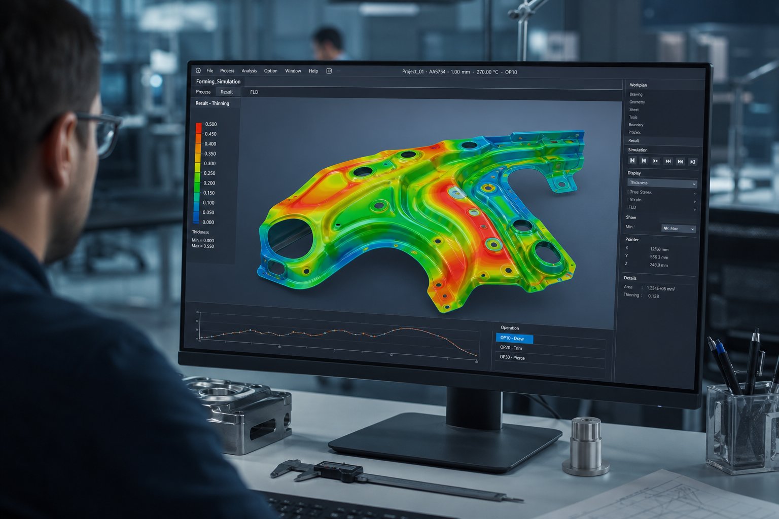
Modern progressive stamping die design relies heavily on forming simulation before any steel is cut. Finite element analysis (FEA) software predicts exactly where material will thin excessively, where spring-back will push formed angles out of tolerance, and where wrinkles will develop during drawing. Keysight reports that virtual die tryouts allow manufacturers to predict and prevent defects early in the design phase, replacing the costly trial-and-error methods that once dominated progressive die development.
Simulation also addresses the station-count trade-off. Adding more stations to a die increases tooling cost but can improve part quality by distributing forming forces across gentler increments. FEA helps engineers find the sweet spot - the minimum number of stations needed to achieve target geometry without exceeding material thinning limits or spring-back tolerances. For complex parts, simulation might reveal that splitting a single aggressive form into two progressive stations eliminates cracking risk entirely, justifying the added die cost through reduced scrap and higher press speeds.
Grain direction further influences layout decisions. Critical bends should cross perpendicular to the rolling direction whenever possible, since bending with the grain increases cracking risk - especially in harder tempers. Sometimes this means orienting the strip layout in a less material-efficient direction, accepting a slightly higher scrap rate to ensure consistent bend quality across every part. Simulation quantifies this trade-off, showing exactly how much formability improves versus how much material utilization drops, giving engineers hard numbers instead of guesswork.
The payoff for investing in DFM analysis and simulation up front is measurable: fewer die modifications after tryout, faster time to production-ready tooling, lower scrap rates, and dies that run millions of cycles without the chronic issues that plague poorly designed tools. These savings compound quietly across every part produced - which is exactly where the real cost story of progressive stamping begins to take shape.
Cost Structure and Break-Even Volume Analysis
DFM savings compound across every cycle - but they only matter if the volume justifies building the die in the first place. The progressive die stamping process front-loads cost into tooling, and understanding exactly where that money goes helps you predict when the investment starts paying back.
What Drives Progressive Die Tooling Costs
Why is progressive so expensive upfront? Because you're engineering an automated factory into a single block of steel. Every feature on your part - every hole, bend, form, and cutoff - requires a corresponding station in the die, and each station demands precision-machined punches, die blocks, and guides. The cost scales directly with complexity.
Four factors dominate the tooling quote:
- Station count - A die with 15 stations requires significantly more CNC machining and wire EDM hours than one with 5 stations. Industry data confirms that machining and complexity account for 30-50% of total die cost.
- Die material - Progressive carbide stamping dies use tungsten carbide inserts at high-wear stations to survive millions of cycles, but carbide costs substantially more than standard D2 or SKD11 tool steel. For shorter production runs, pre-hardened steels reduce initial cost at the expense of earlier maintenance intervals.
- Tolerance requirements - Tighter tolerances demand finer grinding, more precise heat treatment, and longer tryout periods. The tryout and validation phase alone typically represents 10-15% of total die cost.
- Die life requirements - A die engineered for 10 million hits needs premium materials and robust construction that a 500,000-hit tool doesn't. The expected lifespan directly influences material grade, component sizing, and backup punch provisions.
For mid-sized precision components, progressive die tooling generally ranges from $30,000 to over $250,000 depending on these variables. Simpler bracket geometries can come in around $15,000, while complex parts requiring tight tolerances and many forming stations push well beyond $60,000. Die material alone represents 20-40% of the total investment.
Per-Part Economics and Volume Break-Even
Here's where the math flips. That steep upfront cost gets divided across every part the die produces - and at high volumes, the per-unit tooling contribution shrinks to fractions of a cent.
Consider the arithmetic: a $50,000 die producing 500,000 parts adds just $0.10 in tooling cost per piece. The same die producing only 5,000 parts? That's $10.00 per part in tooling alone - before material and press time even enter the equation. This amortization logic is why high speed progressive die stamping only makes economic sense above certain volume thresholds.
Progressive die stamping becomes cost-effective when annual production volumes exceed 50,000 units. Below this threshold, the tooling contribution per part outweighs the cycle-time savings. Above it, per-unit costs drop so sharply that no alternative process can compete for large run stampings of complex parts.
The break-even point is where progressive die cost-per-part crosses below simpler methods. A real-world comparison illustrates this clearly: a simple steel bracket produced with modular short-run tooling ($800 setup) costs $1.10 per part, while the same bracket from a progressive die ($15,000 tooling) costs $0.30 per part. The crossover happens around 17,750 units - below that number, short-run wins; above it, long run progressive stamping dominates the economics decisively.
Ongoing costs don't disappear after the die ships, though. Plan for these recurring expenses:
- Sharpening cycles - Punches dull over time. Reputable shops pull and resharpen tooling every 50,000 to 150,000 hits depending on material hardness.
- Component replacement - Pilots wear, springs fatigue, and die buttons eventually need replacement. Budget roughly 5-10% of die value annually for maintenance.
- Die modifications - Engineering changes after the die is built can cost up to half the original tool price if major rework is required.
The real answer to why progressive tooling carries a premium is that it's an automated production system, not a simple tool. You're paying once to engineer a process that then runs millions of identical parts with minimal labor, minimal scrap, and minimal variation. The expense isn't in making one part - it's in making the next million parts nearly free.
Still, even the best cost model falls apart if the die produces defective parts. The hidden costs of scrap, downtime, and rework can erode those per-unit savings faster than any tooling amortization builds them - which is why quality control inside the die deserves just as much attention as the economics behind it.
Troubleshooting Defects and Quality Control Strategies
Scrap and rework don't announce themselves with flashing lights. Most progressive die defects develop gradually - a punch edge dulling over thousands of strokes, a pilot pin wearing by microns each shift, clearances drifting as thermal expansion builds during a long run. By the time you spot bad parts in the output bin, the die has already produced hundreds more behind them.
Catching problems early - or better yet, preventing them entirely - requires understanding what goes wrong, why it happens, and what modern sensing technology can do about it inside the progressive stamping tool itself.
Common Defects and Root Causes
Every defect has a signature. When you know what to look for, the root cause often points directly back to a specific wear condition or process variable. Here are the most frequent issues that production teams encounter on the die stamping press:
- Burr formation - Excessive material rollover or raised edges on pierced features. The primary causes are worn tooling punches that have lost cutting-edge sharpness or excessive punch-to-die clearance that allows material to tear rather than shear cleanly. Industry troubleshooting data confirms that improper clearance accelerates this cycle: tight clearance overloads the punch, while excessive clearance produces tearing and unstable edge quality. Correction involves resharpening sheet metal punches on schedule and verifying clearance with feeler gauges after each maintenance cycle.
- Strip misalignment - Parts showing inconsistent hole positions, uneven bends, or edge mismatch across stations. Root causes include worn pilot pins that no longer register the strip accurately, feed timing errors where the feeder releases too early or too late, or degraded guide rails that allow lateral drift. In narrow-pitch connector stamping, even microscopic pilot wear creates cumulative dimensional drift long before defects become visually obvious.
- Material thinning and splitting - Localized necking or fractures at formed features, especially draws and tight bends. This results from insufficient die radius (too sharp a corner forces material to stretch beyond its limits), excessive draw depth relative to material thickness, or improper blankholder pressure that allows wrinkling instead of controlled material flow. Balancing draw reductions across multiple stations - rather than maximizing each reduction - significantly reduces thinning risk.
- Slug pulling - Scrap material (slugs) adhering to the punch surface during withdrawal and being carried back onto the strip, causing dents, misfeed, and potential die damage. The vacuum effect between the punch face and slug creates suction that fights scrap evacuation, particularly at higher press speeds. Contributing factors include worn punch faces (increased surface area creates stronger vacuum), insufficient scrap-channel clearance, and poor lubrication. Solutions include air blow systems, spring ejectors, vacuum relief grooves machined into punch faces, and optimized scrap evacuation channel geometry.
- Dimensional drift - Gradual, progressive deviation from nominal dimensions across a production run without an obvious single-point failure. Thermal expansion during long continuous runs subtly alters clearances. Guide pin and bushing wear introduces lateral play between upper and lower die halves. These small shifts compound across stations, eventually pushing parts out of tolerance.
What makes troubleshooting a progressive stamping machine challenging is interconnection. These defects rarely appear in isolation. Punch wear increases burr height, which raises stripping resistance, which causes slug adhesion, which produces strip instability - all from one original wear condition cascading through the system. Experienced toolmakers trace symptoms backward through this chain rather than treating each defect independently.
Quality Control Strategies and Modern Sensing
Traditional quality control relied on spot checks - pulling a part every 20 or 50 strokes and measuring it with calipers or an optical comparator. The problem? Between checks, a progressive stamping tool running at 300 strokes per minute can produce thousands of parts. If something shifts, you're sorting scrap by the bin.
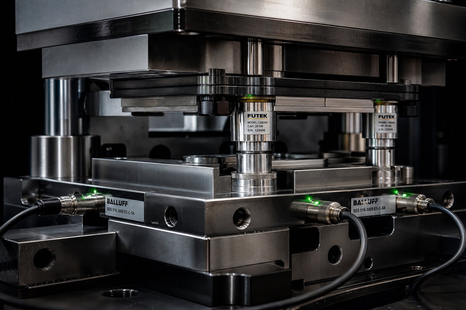
In-die sensing technology changes that equation fundamentally. Sensors installed directly in the tooling monitor process variables in real-time, stroke by stroke, detecting anomalies within a single cycle of deviation. The Fabricator reports that in-die sensing progressed from simply preventing die crashes to actively monitoring part quality and even auto-correcting the process between strokes.
Key sensing strategies used in modern progressive stamping include:
- Tonnage monitoring - Load cells on the press frame detect changes in forming force that indicate punch breakage, material thickness variation, or lubrication starvation. A sudden force spike signals a potential crash; a gradual increase suggests punch dulling.
- Stripper level sensors - Proximity sensors mounted at the corners of the lower die monitor whether the stripper plate closes to its full depth each stroke. If a pulled slug sits on the strip, at least one corner won't reach the sensor's field, triggering an immediate press stop - detecting the problem within one stroke of occurrence.
- Punch presence detection - Optical sensors verify that small-diameter punches remain intact every cycle. For punches that are small relative to material thickness and prone to breakage, this catches failures before broken punch fragments damage the die.
- Feed progression validation - Sensors confirm that the strip has advanced the correct pitch distance before the press cycles again, preventing double-hits or partial feeds that destroy tooling.
Servo press technology adds another dimension of control. Unlike conventional mechanical presses that follow a fixed slide motion profile (sinusoidal), servo-driven presses allow programmable slide velocity and dwell time throughout the stroke. Engineers can slow the ram during forming to reduce impact forces, add a dwell at bottom dead center for better material flow in draws, or speed through non-working portions of the stroke to maintain cycle rates. This programmability enables tighter process windows for difficult materials like stainless steel or high-strength alloys that are sensitive to forming speed.
Closed-loop systems represent the highest tier of in-die quality control. Analog sensors measure formed angles or material thickness every stroke and feed that data to servo-actuated wedge adjustments within the die. If a bend angle drifts 0.3 degrees from nominal, the system automatically compensates between strokes - correcting the process without stopping the press. This approach converts a reactive inspection program into a self-correcting production system.
Statistical process control (SPC) ties all this data together. By trending force signatures, dimensional measurements, and sensor outputs over time, engineers identify wear patterns before they produce defective parts. A punch that will fail at 100,000 strokes shows measurable force changes starting around 70,000 - giving maintenance teams lead time to schedule sharpening during planned downtime rather than reacting to a crash.
Process Limitations Worth Acknowledging
No process is universal, and progressive die stamping has boundaries that honest evaluation should address:
- Deep draws - Parts requiring draw depths exceeding approximately 1x material thickness push past what carrier-attached strip forming can achieve. Deeper geometries need transfer dies where the blank separates early for unrestricted redrawing.
- Thick stock - Materials above roughly 6 mm (0.250 in.) thickness demand press tonnages and die clearances that make progressive tooling impractical. The forces involved would require massive die structures, and feed mechanisms struggle to advance heavy strip reliably at speed.
- Secondary operations - Tapping, welding, plating, and certain assembly steps cannot be performed in-die. Parts requiring these operations need post-stamping processing, adding handling and potential dimensional variation.
- Very large parts - Strip-width limitations of coil stock constrain part size. Components exceeding roughly 150 mm in their largest dimension typically outgrow progressive die envelopes.
Knowing these boundaries prevents forcing a progressive solution where it doesn't fit - and prevents quality problems that stem from pushing the process past its inherent limits. When part requirements sit comfortably within those boundaries, the combination of proactive die design, in-die sensing, and disciplined maintenance creates a production system that holds tolerance over millions of cycles with minimal human intervention.
That reliability at scale is exactly what makes progressive die tooling attractive as a sourcing strategy. But choosing the right die partner - one who integrates these quality systems from the design phase forward - determines whether you actually achieve those results in practice.
Sourcing Progressive Stamping Dies for Scalable Production
Reliability at scale depends on more than good die design - it depends on who builds and supports that tooling over its entire production life. Whether you're launching a new part or reshoring an existing program, selecting the right progressive die manufacturer shapes everything from first-article timelines to long-term cost-per-part performance.
What to Evaluate in a Die Supplier
Progressive die metal stamping is a systems discipline. The supplier you choose isn't just cutting steel - they're engineering a production process. That means your evaluation criteria need to go beyond price-per-station and delivery dates. Industry guidance from Eigen Engineering identifies eight critical dimensions for assessing progressive tool and die partners, from customization capability to after-sales technical support.
Here's what separates strong progressive die manufacturers from the rest:
- In-house die design and simulation - Suppliers running FEA-based forming simulation and CAD/CAM strip layout analysis catch thinning, spring-back, and interference problems before steel is cut. This reduces tryout iterations by 30-50% compared to trial-and-error shops.
- Material expertise across alloys - A capable partner understands how copper, stainless, aluminum, and high-strength steel each behave in progressive dies - and adjusts clearances, coatings, and station sequencing accordingly.
- Press tonnage range and speed capability - Ask what presses are available for tryout and validation. As Winco Stamping recommends, confirm standard press tonnage range, stroke length, and material thickness limits upfront.
- Quality certifications - ISO 9001 at minimum. For automotive or medical applications, look for IATF 16949 compliance or equivalent quality management systems with documented process control.
- Ongoing die maintenance support - Progressive die stamping services don't end at shipment. Sharpening schedules, component replacement, and engineering change support determine whether a die still performs at stroke 5 million the way it did at stroke 5,000.
- Scalability - Your volumes may grow. A supplier that can scale from prototype validation through full production ramp-up - without requiring you to re-source tooling - eliminates transition risk.
YICHEN Progressive Stamping Dies for Scalable Production
For production engineers and procurement teams evaluating progressive die stampings suppliers, YICHEN offers progressive stamping dies engineered specifically for high-volume metal parts requiring efficient multi-station forming and tight repeatability. Their dies support scalable mass production across a range of alloys and part geometries - making them a practical option for teams that need a progressive die manufacturer capable of supporting both initial tooling and ongoing production demands.
When vetting any supplier on this list, request sample strip layouts, documented tryout data, and references from similar production volumes. The best progressive tool and die partners welcome scrutiny because their engineering holds up under it. The worst hide behind polished brochures. Your per-part economics - and your production uptime - depend on knowing the difference.
Frequently Asked Questions About Progressive Die Stamping
1. What is the progressive die stamping process and how does it work?
Progressive die stamping is a coil-fed metalworking method where a continuous metal strip advances through multiple stations inside a single die. Each station performs a specific operation such as piercing, blanking, bending, or forming. The strip moves one fixed pitch distance per press stroke, with pilot pins ensuring precise alignment at every station. The finished part separates at the final cutoff station. This parallel processing allows high-speed presses to produce thousands of identical parts per hour with minimal operator intervention.
2. Why is progressive die tooling so expensive compared to other stamping methods?
The upfront cost reflects the complexity of engineering an entire automated production sequence into one tool. Costs scale with station count, die material grade (carbide vs. tool steel), tolerance requirements, and expected die life. A typical progressive die ranges from $30,000 to over $250,000. However, this investment amortizes across production volume - a $50,000 die producing 500,000 parts adds only $0.10 per piece in tooling cost. The break-even point where progressive dies become cheaper than simpler methods typically falls around 50,000 units annually, after which per-part costs drop dramatically below any alternative process.
3. What is the difference between progressive die and transfer die stamping?
The key difference is workpiece handling. In progressive die stamping, the part stays attached to the carrier strip throughout all stations, making it ideal for small, complex parts at very high speeds (200-400+ strokes per minute). Transfer die stamping separates the blank from the strip at the first station and uses mechanical fingers to move it between independent die stations. This allows deep draws and larger part sizes but runs slower (20-60 SPM). Choose progressive dies for small multi-feature parts at high volume, and transfer dies for larger or deeply drawn components.
4. What materials work best for progressive die stamping?
Low-carbon steel (C1008-C1020) is the most forgiving material with minimal spring-back and excellent die life. Copper and brass alloys offer very high formability and are preferred for electrical components. Aluminum provides weight savings but requires coated tooling to prevent galling. Stainless steel handles corrosion-critical applications but work-hardens aggressively, demanding wider clearances and heavier lubrication. Material selection should balance part function, formability, tooling wear impact, and total production cost rather than raw material price alone.
5. How do you choose a reliable progressive die manufacturer?
Evaluate suppliers on in-house die design with FEA simulation capability, material expertise across multiple alloys, available press tonnage range, quality certifications (ISO 9001 or IATF 16949), and ongoing maintenance support. Strong suppliers like YICHEN provide progressive stamping dies engineered for high-volume production with tight repeatability and scalable output. Request sample strip layouts, documented tryout data, and production references at similar volumes. A capable partner should welcome technical scrutiny and demonstrate the ability to support your program from prototype through full-scale ramp-up.


