


What Is Progressive Die Stamping and Why It Matters
Imagine feeding a flat ribbon of metal into a machine and watching it emerge seconds later as a fully formed, production-ready part. No repositioning, no separate setups, no operator intervention between steps. That is exactly what progressive die and stamping delivers at scale, and it is one of the most efficient metal forming methods ever developed for repeatable, high-volume production.
Defining Progressive Die Stamping
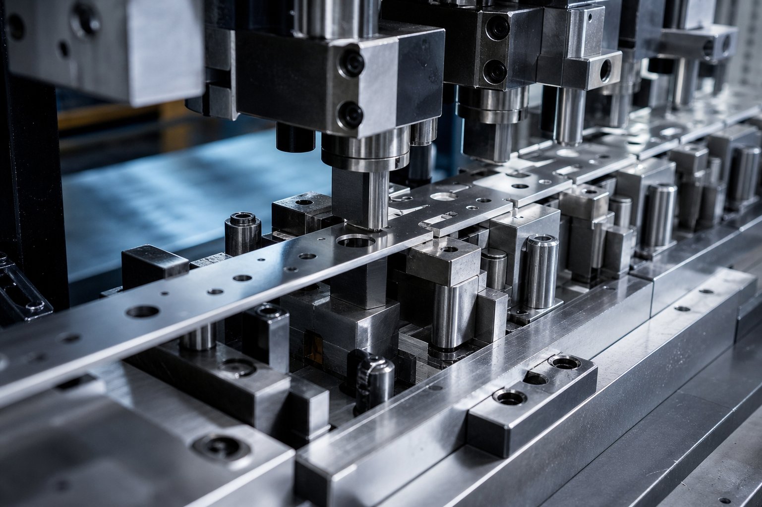
Progressive die stamping is a high-volume metal forming process in which a continuous strip of metal advances through a single die tool containing multiple stations, each performing a specific operation such as piercing, bending, or blanking, until a finished part is produced with every stroke of the press.
So what is a progressive die, exactly? Think of it as a series of specialized workstations built into one compact tool. A coil of sheet metal feeds into the press, and with each stroke, the strip moves forward a fixed distance called the pitch. At every station, a different operation shapes the metal a little further. By the final station, the completed part separates from the strip and drops into collection, while the next part is already taking shape behind it.
The word "progressive" describes the core idea: the metal progresses station by station, each step building on the last. This concept traces back to around 1900 and became widely practiced by the 1950s, when industry demanded consistent, interchangeable metal parts at volumes that manual methods could never achieve. The fundamental principle remains unchanged today, refined by better materials, servo-driven presses, and modern simulation software.
Where Progressive Die Stamping Fits in Manufacturing
Metal forming spans a wide spectrum. On one end, you have single-stage dies and manual brake press operations suited for prototypes or short runs. On the other end, fully automated transfer press lines handle very large parts or extremely deep draws. Progressive stamping bridges that gap, making it the dominant choice for medium-to-high volume precision parts where speed, consistency, and per-piece cost all matter.
You will find components produced through progressive dies and stamping operations in nearly every sector that relies on metal parts at scale. Automotive brackets, electronic connectors, medical device housings, HVAC mounting clips: all benefit from a process that can hold tolerances of a few thousandths of an inch while running at hundreds of strokes per minute. When annual volumes climb into the tens or hundreds of thousands, few alternatives can match the economics of progressive stamping.
What makes this process particularly compelling is that a single tool can combine cutting, bending, drawing, and coining operations in one continuous cycle. There is no inter-station handling, no accumulation of positioning errors, and no operator variation from part to part. The millionth piece off a well-maintained die is dimensionally identical to the first.
Understanding the general concept is straightforward. The real depth, the part that separates informed buyers from everyone else, lives in the details of how each station works, what the tooling actually contains, and where the economics tip in your favor. Those details shape every decision from material selection to supplier qualification.
How the Progressive Die Stamping Process Works Station by Station
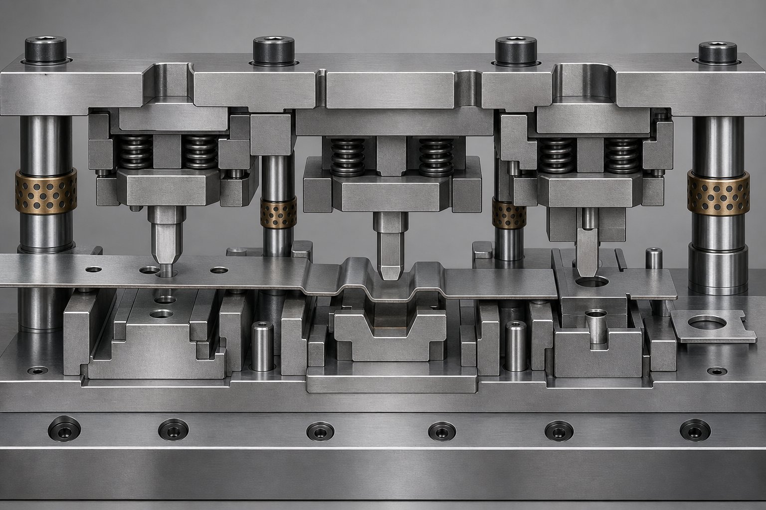
How does a stamping press work when it runs a progressive die? From the outside, you see a coil of metal feeding in and finished parts dropping out. But inside that tool, a carefully choreographed sequence of operations transforms flat strip into a three-dimensional component in fractions of a second. Here is what actually happens at each stage of the die process.
Coil Feeding and Strip Progression
Everything begins at the uncoiler, where a roll of sheet metal, sometimes weighing thousands of pounds, is mounted and ready to feed. The strip passes through a straightener that removes the natural curvature (called coil set) imparted by being wound on a spool. Without this step, the material would bow and buckle inside the die, causing misfeeds and dimensional errors.
From the straightener, a servo feeder advances the strip into the progressive stamping press by a precise distance called the feed pitch. This pitch matches the spacing between die stations, so each stroke positions fresh material exactly where it needs to be. But the feeder alone does not guarantee perfect alignment. That job belongs to pilot pins: hardened pins mounted in the upper die that drop into pre-pierced holes in the strip just before each station performs its operation. Pilots correct any minor feed error, typically holding strip registration to within 0.0005 to 0.001 inches. Without reliable piloting, tolerance drift accumulates station by station and scrap rates climb.
Station Operations Explained
Each station in a progressive die performs a specific task, and the sequence is engineered to minimize material stress while maintaining strip integrity. Here is the typical order of operations in a progressive stamping process:
- Piercing - Punches descend through the strip to create holes, slots, and internal features. This usually happens first because pilot holes are needed for registration at subsequent stations, and cutting internal features early avoids distorting them during later forming.
- Notching - Material is removed from the edges of the strip to define the outer profile of the part or to create clearance for upcoming bends. Unlike piercing, notching opens the strip boundary, which means engineers must ensure enough carrier material remains to transport the part forward.
- Lancing - A hybrid operation that cuts and bends in a single stroke. A lance creates a tab or louver by shearing along part of a line and folding the freed section upward or downward. It is efficient because it forms a feature without fully separating material from the strip.
- Forming - The strip is bent into three-dimensional geometry: angles, channels, ribs, or complex contours. Forming stations use shaped punches and die cavities to push the metal into its final profile. Because forming introduces stress, it is sequenced after most cutting operations to avoid distorting previously made holes or edges.
- Coining - Metal is compressed between flat or shaped surfaces under high tonnage to achieve very tight dimensional tolerances or specific surface finishes. Coining displaces material rather than cutting it, making it ideal for calibrating thickness, flattening localized areas, or embossing fine detail.
- Blanking - The final station separates the completed part from the carrier strip. A blanking punch shears along the remaining perimeter, and the finished component drops free. At this point, every feature has already been formed and calibrated, so the part is ready for inspection or downstream processing.
Not every die uses all six operation types, and some parts require additional stations such as trimming, drawing, or in-die tapping. The critical point is that station sequence is never arbitrary. Engineers plan each step so that cutting forces are balanced, formed features do not interfere with strip advancement, and material flow remains predictable throughout the cycle.
Scrap Management and Part Ejection
Every piercing, notching, and blanking operation generates scrap. Those small cutout pieces, called slugs, must exit the die reliably. In most progressive dies, slugs fall downward through clearance holes in the die block and lower shoe, dropping into scrap chutes or bins beneath the press. If a slug sticks to a punch and gets pulled back up into the die (a defect known as slug pulling), it can damage the next part or even crack a punch.
The carrier strip itself, now a skeleton of bridges and leftover material, exits the back of the die and is either chopped into short lengths or wound onto a scrap reel. Meanwhile, finished parts are ejected by one of several methods: gravity drop through a die opening, air blasts that push parts onto a conveyor, or mechanical kickers that direct them into collection bins.
Reliable scrap removal is not a minor detail. At press speeds of 200 to 1,000 strokes per minute, even a single stuck slug can halt production and require die removal for clearing. That is why experienced die designers plan straight, unobstructed drop paths and incorporate slug retention features like ejector pins or textured die openings during the initial design phase.
With the physical process clear, the next logical question is what is actually inside this tooling, the specific components that make each station function, wear over time, and ultimately determine how long a die performs before needing service.
Anatomy of a Progressive Die and Its Key Components
When you invest in progressive die tooling, you are not buying a single block of hardened steel. You are buying a precision assembly of dozens of components, each with a specific role, each subject to wear, and each replaceable when it reaches end of life. Understanding what is inside that tool gives you a clearer picture of where your money goes, why lead times are what they are, and what drives maintenance costs down the road.
Die Set Foundation and Structural Components
Every progressive die is built on a die set: a matched pair of thick steel plates called the upper shoe and lower shoe. The upper shoe bolts to the press ram; the lower shoe clamps to the press bed. Together, they form the rigid skeleton that holds every other component in alignment.
Connecting the two shoes are guide posts and guide bushings. These hardened pins and sleeves ensure the upper and lower halves meet in exactly the same position on every stroke. Typical guide pin tolerances run within 0.0001 inches, tight enough to maintain cutting clearances even under repeated high-tonnage impacts at production speed. Ball-bearing guide pins have become the industry standard because they allow smoother separation of the die halves and reduce asymmetric wear over time.
Heel blocks, mounted near the corners of the die set, absorb lateral forces generated during cutting and forming. Without them, side loads would shift the upper half relative to the lower, causing uneven punch wear and dimensional drift in finished parts.
Mounted to the upper shoe, you will find punch plates and punch retainers that hold cutting and forming punches in precise position. Backing plates sit behind the punch retainers to distribute impact loads across a wider area, preventing the punches from driving back into the softer shoe material under repeated cycling.
Functional Elements That Control the Strip
Structural components keep the die aligned. But a second category of parts controls the metal strip itself, making sure it sits flat, stays centered, and registers accurately at every station.
Strippers are spring-loaded plates that press down on the material as the upper die descends. They serve two purposes: holding the strip flat against the lower die surface during cutting and forming, and stripping the material off the punches as the press opens. Without adequate stripper force, the strip can lift with the punches, deform, or misfeed on the next stroke.
Stock guides are precision channels machined into the lower die that keep the strip aligned laterally. They prevent the material from drifting side to side as it advances, which would throw off every feature location relative to the strip edge.
Pilots are hardened pins that enter pre-pierced holes in the strip just before each station does its work. They correct any residual feed error and lock the strip into true position. Pilot clearance to the hole is typically 0.0005 to 0.001 inches, and pilot length must be calculated so the pin enters the strip before other punches engage but does not bind or pull material upward when the die opens.
Lifters are spring-loaded devices that raise the strip off the lower die surface between press strokes. This clearance allows the feeder to advance the material to the next pitch position without dragging across forming features or die surfaces. Stamping die lifters must be timed carefully with the feed system: the feed roll remains open until the lifters reach full travel, then closes just before the pilot tips exit the strip. Misjudging this timing window is one of the most common causes of progression loss in production.
These elements work as a system. Guides position the strip laterally, lifters elevate it for feeding, the feeder advances it one pitch, and pilots lock it into final registration before the strippers clamp it flat for the next operation. Remove any one element from that chain and repeatability breaks down.
Wear Components and Serviceability
Sounds like a lot of components to maintain? It is, but modern stamping dies are designed for modularity. The parts that wear fastest, punches, die buttons, pilots, and springs, are built as replaceable inserts rather than integral features of the die block. When a punch dulls or chips, a technician can pull that single insert and replace it without disassembling the entire tool.
Material choice for these inserts depends on production volume and the material being stamped:
- Tool steel (A2, D2, M2) - Good balance of toughness and wear resistance; standard choice for most progressive dies running mild steel or aluminum
- Carbide inserts - Extremely high wear resistance but more brittle; used for high-speed production, abrasive materials like stainless steel, or applications demanding extended runs between sharpening
- Punch plates and retainers - Hold cutting tools in position; available in ball-lock, shoulder, and trumpet-head styles for quick changeout
- Die buttons - Female cutting components paired with punches; offset slightly larger than the punch nose (typically 5-10% of material thickness) to create the clearance needed for clean shearing
- Die springs (mechanical and nitrogen gas) - Provide stripping force and hold-down pressure; nitrogen gas springs offer higher force in a smaller envelope
- Guide pins and bushings - Alignment system; replaced when wear exceeds allowable tolerance
- Stamping die lifters and pilots - Strip control elements subject to constant contact with advancing material; replaced on a preventive schedule
This modular approach means a well-designed progressive die can produce millions of parts over its lifetime with periodic component swaps rather than complete rebuilds. The die set itself, the shoes, guide posts, and heel blocks, rarely needs replacement. The real ongoing investment is in the consumable inserts and springs that take the brunt of each press cycle.
Choosing between carbide and tool steel inserts is not purely a cost decision. Carbide lasts significantly longer between sharpening intervals but costs more upfront and is more vulnerable to chipping if the die experiences a misfeed or crash. For most stamping dies running under 500,000 cycles between maintenance windows, D2 tool steel offers the best balance. Beyond that threshold, or when stamping abrasive stainless or high-strength alloys, carbide pays for itself in reduced downtime.
Knowing what lives inside the tooling is half the equation. The other half is understanding which materials that tooling can process and how those materials influence press selection, tonnage requirements, and ultimately production speed.
Material Selection and Press Requirements
Every progressive metal stamping project starts with a fundamental question: what metal are you forming? The answer shapes everything downstream, from tonnage calculations and press speed to lubrication strategy and die insert material. Get this decision right and your tooling runs for millions of cycles. Get it wrong and you face cracked punches, excessive burrs, or a die stamping press that stalls at bottom dead center because it ran out of energy mid-stroke.
Metals Suited for Progressive Die Stamping
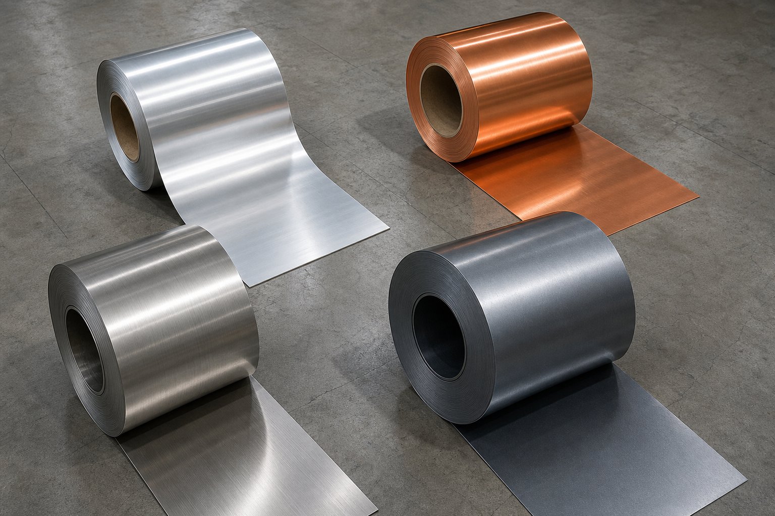
Progressive die metal stamping handles a broad family of alloys, but each brings its own personality to the press. Here is how the most common progressive stamping materials compare:
| Material | Formability | Typical Gauge Range | Tonnage Demand | Common Applications |
|---|---|---|---|---|
| Low-Carbon Steel (CRS/HRS) | Excellent | 0.010" - 0.125" | Moderate | Automotive brackets, structural clips, HVAC mounting hardware |
| Stainless Steel (300/400 series) | Good, work-hardens quickly | 0.010" - 0.090" | High (40-60% more than CRS) | Medical components, food equipment, appliance parts |
| Aluminum (1100, 3003, 5052) | Very good, soft | 0.012" - 0.125" | Low | Electronics enclosures, heat sinks, lightweight structural parts |
| Copper (C110, C102) | Excellent, very malleable | 0.005" - 0.060" | Low to moderate | Electrical terminals, bus bars, connectors |
| Brass (C260, C270) | Very good, ductile | 0.008" - 0.080" | Low to moderate | Hardware, decorative trim, electrical contacts |
Low-carbon steel dominates progressive stamping because it offers excellent formability, predictable springback, and low material cost. It punches cleanly, bends without cracking, and wears tooling at manageable rates. Stainless steel brings corrosion resistance but demands higher tonnage and accelerates punch wear due to work hardening, making carbide inserts a frequent requirement.
Aluminum is lightweight and easy to shear, but it scratches easily against die surfaces and tends to gall without proper lubrication. Water-based lubricants and polished die surfaces are standard practice. Copper progressive stamping serves electrical and thermal applications where conductivity matters more than strength. Copper and brass are soft, easy to form, and produce clean edges, but their malleability means burrs can develop if punch-to-die clearances are not held tight.
Gauge ranges typically processed in progressive dies span from about 0.005 inches for delicate electronic terminals up to 0.125 inches for structural brackets. Coil widths commonly range from one inch to around 24 inches, though the practical limit depends on press bed size and die dimensions.
Press Selection Criteria
Material type and part geometry together determine what your progressive die press needs to deliver. Three factors matter most: tonnage capacity, stroke length, and speed rating.
Tonnage is the peak force the press must generate. For piercing and blanking operations, the calculation follows a straightforward formula: perimeter of the cut multiplied by material thickness multiplied by the shear strength of the metal. For forming and drawing stations, the calculation uses tensile strength and accounts for part geometry. You sum the forces across all active stations, add loads from spring strippers, lifters, and cams, then apply a safety margin, typically 20 to 30 percent. According to industry practice, the generic equation for any trim or pierce operation is Tonnage = Perimeter x Thickness x Shear Strength, where shear strength is roughly 60% of tensile strength for most steels.
But tonnage alone does not tell the full story. A press must also deliver enough energy through the stroke to complete all operations without stalling. A mechanical press may have sufficient peak tonnage at bottom dead center but lack the flywheel energy to sustain force through a deep draw that begins several inches off bottom. This distinction becomes critical when stamping thicker gauges or high-strength alloys.
Stroke length must accommodate the deepest forming operation in the die plus clearance for strip lifting and part ejection. Too short a stroke and you cannot physically form the part. Too long wastes cycle time on non-productive travel.
Press speed directly governs production economics. Mechanical presses with conventional flywheels excel at high-speed blanking and piercing of simple parts, routinely hitting 400 to 1,200 strokes per minute for shallow operations. Servo-driven presses offer a different advantage: programmable slide velocity. A servo press can slow the ram during the forming portion of the stroke for better material flow, then accelerate through the non-working portion to maintain throughput. As MetalForming Magazine explains, servo presses allow stampers to fine-tune speed at impact while maintaining the highest possible production rate, making them ideal for copper progressive stamping and other materials sensitive to impact velocity.
Servo presses also support pendulum mode, where the shaft reverses direction rather than completing a full 360-degree rotation, effectively shortening the stroke cycle and boosting output for parts that do not need full ram travel. The tradeoff is cost: servo presses carry a higher initial investment than conventional mechanical presses, so the choice depends on whether your part geometry and material truly demand variable slide motion or whether a simpler constant-speed press will do.
Finally, bed size must accommodate your die footprint with room for clamping hardware and scrap chutes. An undersized bed forces compromises in die layout or requires running the tool off-center, which accelerates frame wear and degrades part quality over time. The general rule: select a press bed at least two to four inches larger than the die shoe in each direction.
Material and press selection are interdependent decisions. The alloy you stamp determines the forces your die must withstand, the speed at which you can safely run, and ultimately the cost per part at production volume. Choosing wrong on either side ripples through the entire program. But even with perfect material and press pairing, the value of progressive die stamping only becomes clear when you compare it head-to-head against alternative stamping methods, each with its own strengths and blind spots.
Progressive Die vs Transfer Die vs Compound Die
Knowing how progressive die stamping works is one thing. Knowing when it is the wrong answer for your part is where real money gets saved or wasted. Every stamping method exists because certain part geometries, volumes, and tolerance demands favor one approach over another. The question is never "which process is best" in absolute terms. It is always "which process is best for this specific part at this specific volume."
Progressive Die vs Transfer Die Stamping
The most common comparison buyers face is progressive versus transfer die stamping. Both use multiple stations to form a finished part. The fundamental difference? How the workpiece moves between those stations.
In a progressive die, the part stays attached to the carrier strip from first station to last. The strip itself is the transport mechanism. The part only separates at the final blanking station. This keeps things fast and eliminates inter-station handling, but it imposes a constraint: the part must physically remain connected to a flat strip throughout every operation.
Transfer die stamping takes a different approach. The part is separated from the strip early, often at the very first station, and mechanical fingers or transfer rails physically pick it up and move it between stations. Each station operates on a discrete blank rather than a connected strip.
When does transfer stamping become necessary? Three scenarios push you toward transfer tooling:
- Very deep draws - Because there is no carrier strip restricting material flow, transfer dies can punch as deep as the raw material allows. Progressive dies are limited in draw depth because the strip connection restricts how far metal can move into a cavity.
- Large parts that exceed strip width - If your part footprint is bigger than practical coil widths (roughly 24 inches for most progressive setups), transfer dies handle the part as a pre-cut blank with no width constraint.
- Operations requiring access to all edges - When you need to form, trim, or add features along every perimeter of the part, the carrier strip in a progressive die literally gets in the way. Transfer dies free all edges for tooling access.
Transfer die stamping is commonly used for large body panels, structural components, and heavy-duty enclosures in automotive and industrial applications where part size and depth make progressive dies impractical. The tradeoff is cycle time: mechanical transfer between stations adds milliseconds per stroke, and the additional handling mechanisms increase tooling complexity. For medium-to-large parts requiring multiple deep draws and intricate shaping, though, transfer dies remain unmatched.
Progressive Die vs Compound Die vs Single-Stage
Not every stamping job needs multiple stations in sequence. Compound die stamping performs several cutting operations in a single press stroke. Imagine a washer: you need an outer circle cut and an inner hole punched. A compound die does both simultaneously, producing a flat, finished part with one hit.
This makes compound dies efficient for flat parts with multiple holes, slots, or perimeter features that do not require any bending or forming. Because everything happens in one stroke, compound stamped parts tend to be flatter than progressively stamped equivalents, since there is no accumulated stress from sequential operations. Compound tooling is also less costly and faster to build than progressive tooling, making it attractive when budgets are tight and part geometry is simple.
The limitation is clear: compound dies only cut. If your part needs bends, draws, embosses, or any three-dimensional forming, you need either a progressive die or a separate forming operation downstream.
Single-stage tooling sits at the simplest end of the spectrum. One die, one operation, one stroke. Need a hole punched? One stage. Need a flange bent? Another stage in a different die. The part is manually or semi-automatically moved between operations. This approach works for very low volumes, extremely large parts that cannot fit in multi-station tooling, or prototyping where you are validating geometry before committing to expensive multi-station dies.
The per-part cost with single-stage tooling is high because of labor and handling time, but the upfront tooling investment is minimal. For annual volumes under a few thousand parts, it often makes more financial sense to absorb higher per-part labor than to spend six figures on a progressive die that takes months to build.
Decision Framework Based on Volume and Geometry
Choosing the right method comes down to four variables: how many parts you need per year, how big they are, how geometrically complex they are, and how tight your tolerances must be. Here is how those variables map across methods:
| Criteria | Progressive Die | Transfer Die | Compound Die | Single-Stage Tooling |
|---|---|---|---|---|
| Part Size Range | Small to medium (up to ~24" strip width) | Medium to large (no strip width constraint) | Small to medium (flat parts only) | Any size |
| Ideal Annual Volume | 50,000 to millions | 10,000 to 500,000+ | 10,000 to 500,000 | Under 5,000 |
| Geometric Complexity | High (2D and 3D features, bends, draws) | Very high (deep draws, all-edge access) | Low (flat cutting operations only) | Low to moderate (one feature per setup) |
| Typical Tolerance | ±0.001" to ±0.005" | ±0.002" to ±0.010" | ±0.001" to ±0.003" | ±0.005" to ±0.015" |
| Relative Tooling Cost | High | High to very high | Low to moderate | Very low |
| Per-Part Cost at Volume | Very low | Low to moderate | Low | High |
| Cycle Speed | Very fast (200-1,200+ SPM) | Moderate (20-80 SPM) | Fast (100-600 SPM) | Slow (manual handling) |
A few practical rules emerge from this comparison. If your part is flat with holes and requires no forming, compound dies likely give you the best balance of tooling cost and per-piece economics. If your part has bends, forms, or complex features and you need volumes above 50,000 annually, progressive dies are almost always the answer. If your part requires deep draws, is physically large, or demands operations on all edges, transfer dies are your path.
Single-stage tooling is rarely a long-term production solution. It serves as a bridge: proving out a design at low volumes before committing to multi-station stage tooling, or handling one-off prototype runs where the geometry is still evolving. Once volumes justify the investment, most manufacturers migrate to progressive or transfer dies and never look back.
One nuance often overlooked: these methods are not mutually exclusive within a production program. A part might begin life in a progressive die for primary forming and then move to a secondary single-stage operation for a feature that cannot be achieved while attached to the carrier strip. Understanding where each method excels lets you architect a manufacturing plan that combines them strategically rather than forcing one process to do everything.
The comparison framework clarifies which approach fits your geometry and volume. What it does not reveal is the cost structure behind each option, specifically what drives tooling price, where the economic crossover points fall, and how production speed translates into per-part savings at scale.
Cost Structure and When Progressive Stamping Pays Off
Here is what trips up most first-time buyers: the price tag on a progressive die feels enormous until you divide it by the number of parts it produces. Progressive die stampings can cost fractions of a cent per piece at volume, but that only happens when the upfront tooling investment, production volume, and press speed align correctly. Misjudge any of these three and the economics collapse.
Tooling Cost Drivers
What determines whether your progressive die costs $15,000 or $150,000? Several factors stack on top of each other:
- Number of stations - Every operation (pierce, form, coin, blank) requires its own station. A simple blank-and-bend part might need 4 to 6 stations. A complex connector with multiple bends, embosses, and tight-tolerance features could demand 12 to 20 stations. Each station adds machining time, material, and engineering.
- Die complexity and forming difficulty - Deep draws, in-die tapping, cam-actuated side actions, and multi-axis forming all require specialized mechanisms that increase both design hours and build cost.
- Insert material - Carbide inserts last significantly longer than tool steel (D2 or SKD11) but cost several times more upfront. For long run progressive stamping exceeding millions of cycles between maintenance, carbide pays for itself. For shorter programs, tool steel delivers adequate life at lower investment.
- Tolerance requirements - Tighter tolerances demand finer machining on die components, additional coining stations, and more tryout iterations. Each tenth of a thousandth you tighten adds cost.
- Die life expectations - A die built for 500,000 total parts uses different material grades and construction methods than one built for 10 million. Longer expected life means premium steels, inserted construction for easy maintenance, and more robust guide systems.
- Development and tryout - This is the cost most quotes understate. The iterative process of running trial parts, measuring, adjusting forming stations for springback, and re-running can approach the tool cost itself for complex geometries.
Industry data illustrates the range clearly. Simple progressive dies with basic pierce-and-bend operations typically fall between $10,000 and $25,000. Medium-complexity tooling with 8 to 14 stations and tighter tolerances lands in the $25,000 to $60,000 range, which is where most automotive and electronics applications concentrate. Dies exceeding $60,000 usually involve deep drawing, carbide inserts for abrasive materials, or specialized sensing packages.
The critical insight? Your part design directly controls tooling cost. Every feature you add requires a station. Every tight tolerance you specify requires finer die components and more tryout cycles. Design simplification before tooling commitment is the single highest-leverage cost reduction available.
Volume Thresholds and Per-Part Economics
Progressive die stamping has a cost curve unlike almost any other manufacturing process. The initial investment is steep, but the marginal cost of each additional part is nearly negligible: just raw material and press time. This creates a dramatic crossover point where progressive tooling shifts from expensive luxury to obvious necessity.
Where does that crossover happen? For most applications, 50,000 to 100,000 annual units represents the threshold where progressive tooling delivers clear ROI over alternatives like laser cutting, CNC punching, or single-stage dies. Ultra-simple parts may justify the investment at 30,000 units. Complex parts with high per-piece alternative costs can break even even sooner.
Consider the math. If a bracket costs $5.00 per unit through laser cutting with manual secondary operations, and the same bracket costs $0.50 per unit through progressive stamping, you save $4.50 per part. A $35,000 die investment pays back in under 8,000 parts. At 50,000 annual units, that payback arrives in less than two months of production.
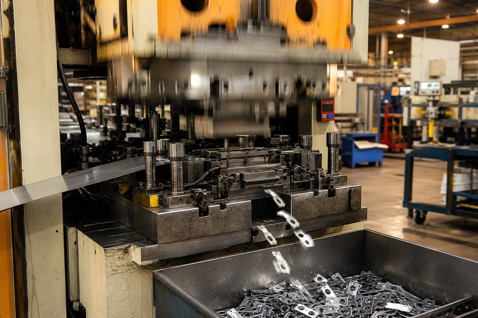
Press speed amplifies the economics further. High speed progressive die stamping at 200 to 600+ strokes per minute means a single press can produce tens of thousands of parts per shift. At those rates, the labor and machine time allocated to each part shrinks to almost nothing. The faster your press runs, the lower your per-part overhead, which is why progressive die metal stamping services emphasize press speed as a core competitive lever for high-volume programs.
The relationship works in reverse too. Below the crossover volume, tooling amortization dominates per-part cost. A $50,000 die spread across 5,000 parts adds $10.00 per piece just in tooling, making alternatives far more attractive.
Lead Time Expectations
Tooling does not appear overnight. From design kickoff to production-qualified parts, expect a timeline measured in months, not weeks. Here is the typical progression:
- Die design and engineering (3-5 weeks) - Strip layout, station sequencing, FEA simulation for forming operations, and detailed component drawings.
- Material procurement (1-3 weeks) - Ordering tool steel blocks, carbide inserts, standard components (springs, guide pins, sensors), often overlapping with design.
- Machining, grinding, and heat treatment (5-8 weeks) - CNC machining of die shoes, plates, and inserts; wire EDM for complex profiles; heat treatment to harden cutting components; precision surface grinding for final dimensions.
- Assembly and bench fitting (1-2 weeks) - Assembling all components, verifying fits and clearances, setting timing.
- Tryout and iteration (2-4 weeks) - Running trial samples, measuring critical dimensions, adjusting forming stations for springback, re-running until parts meet specification.
- Production qualification (1-2 weeks) - Running at production speed, verifying SPC capability, first article inspection approval.
Total timeline for a high-quality progressive die typically runs 12 to 20 weeks. Simple tooling with fewer stations can compress to 8 to 10 weeks. Complex dies with tight tolerances or many forming stations can stretch longer, particularly when tryout reveals springback issues that require multiple correction cycles.
One timeline risk that catches buyers off guard: late-stage design changes. Modifying a die after machining is complete can cost as much as half the original tool price and add weeks to the schedule. Freezing part design before steel cutting begins is not optional. It is the single most important schedule and budget protection available.
Cost, volume, and timeline form the economic triangle of any progressive stamping program. But economics alone do not guarantee success. The other half of the equation, maintaining part quality across millions of cycles while keeping the die in peak condition, determines whether those favorable per-part economics actually hold up in production.
Tolerances, Quality Control, and Die Maintenance
Favorable per-part economics mean nothing if the parts themselves drift out of specification halfway through a production run. A progressive stamping die can hold remarkable precision, but only when you understand what tolerance ranges are realistic for each operation type, how to monitor quality in real time, and what maintenance cadence keeps the tool performing like new across millions of cycles. This is the chapter most suppliers skip, and it is the one that separates a smooth program from a firefighting exercise.
Dimensional Tolerances and Precision Capabilities
What kind of precision can you actually expect from precision die stamping? The answer depends heavily on which operation produced the feature. Cutting, forming, and coining each have different achievable tolerance windows:
| Operation Type | Typical Tolerance Range | Best-Case (Precision Tooling) | Key Influencing Factors |
|---|---|---|---|
| Piercing/Blanking (hole size, position) | ±0.001" to ±0.003" | ±0.0005" | Punch-to-die clearance, pilot accuracy, die wear |
| Bending/Forming (angle, height) | ±0.5° to ±2° / ±0.005" to ±0.015" | ±0.25° / ±0.002" | Springback compensation, material consistency, press deflection |
| Coining (thickness, flatness) | ±0.001" to ±0.002" | ±0.0005" | Tonnage consistency, die surface condition, material uniformity |
| Profile/Trim (edge location) | ±0.002" to ±0.005" | ±0.001" | Strip registration, die sharpness, material grain direction |
Cutting operations deliver the tightest tolerances because shearing is a relatively predictable mechanical action. The punch enters the material, shear initiates, and fracture propagates through the remaining thickness. As long as clearances are correct and tooling is sharp, hole-to-hole and hole-to-edge dimensions remain extremely consistent.
Forming tolerances are wider because bending introduces springback, the elastic recovery of metal after the punch retracts. Springback varies with material yield strength, thickness, bend radius, and even coil position within the heat lot. Experienced die engineers compensate by overbending, adding restrike stations, or using coining pressure at the bend apex, but some variability remains inherent to the process.
Several factors influence precision across all operation types:
- Die condition - A dull punch produces larger burrs and shifts effective hole size. A worn forming surface allows material to spring further.
- Material consistency - Variation in thickness, hardness, or grain orientation within a coil lot introduces part-to-part differences that even perfect tooling cannot eliminate.
- Press deflection - Under load, press frames deflect. If deflection exceeds die clearance margins, hole quality and burr levels degrade, particularly on off-center stations.
- Thermal expansion - During extended runs at high speeds, friction heat causes die components to expand slightly. A die running at 600 SPM for eight hours can shift dimensions by 0.0005" to 0.001" as temperatures stabilize.
- Pilot accuracy - Since pilots register the strip at every station, any wear on pilot pins or elongation of pilot holes directly translates to positional error on downstream features.
The practical takeaway? Specify tolerances based on function, not aspiration. A tolerance of ±0.001" on a clearance hole that mates with a 0.020"-oversized fastener wastes money on extra coining stations and more frequent die maintenance. Progressive precision metal stampings achieve their best economics when tight tolerances are reserved for truly critical features and the rest of the part uses standard precision ranges.
Quality Control and Inspection Methods
Holding tolerance at the start of a run is straightforward. Holding it at part 500,000 requires a layered quality system that catches drift before it reaches your customer. Modern progressive die operations use both in-process monitoring and post-process inspection to maintain control.
In-process monitoring happens inside and around the die while the press is running. These systems detect problems in real time, often stopping the press before a single bad part is produced:
- In-die sensors - Proximity sensors verify part ejection, strip position, and feature presence at each station. If a part fails to eject or a feature is missing, the press halts immediately.
- Tonnage monitors - Load cells on the press frame track the force signature of every stroke. A sudden spike indicates a slug pull or double-thickness condition. A gradual increase suggests punch wear or material hardness drift.
- Feed length verification - Encoders on the servo feeder confirm that the strip advanced the correct distance. Short feeds or overfeeds are flagged before the next stroke can fire.
- Misfeed detection - Strip-presence sensors confirm the material is in the die and properly positioned before the press cycles. This prevents empty hits that can damage punches or distort the die.
Post-process inspection validates the finished parts against drawing requirements, either on a sampling basis or 100% for critical applications:
- CMM measurement - Coordinate measuring machines map critical dimensions in three-dimensional space, providing exact positional data for hole locations, profile conformance, and datum relationships.
- Optical comparators - Project a magnified shadow of the part onto a calibrated screen for fast visual comparison against toleranced overlays. Ideal for checking profiles and radii.
- Pin and go/no-go gages - Quick functional checks for hole sizes, slot widths, and formed heights during production.
- Statistical process control (SPC) - The backbone of long-run quality management. SPC charts, typically X-bar and R charts, track critical dimensions over time, revealing trends before parts drift out of specification.
SPC deserves extra attention. Imagine you are tracking the diameter of a pierced hole across a production run. Each hour, a technician pulls five consecutive parts and measures the hole. Those measurements feed into X-bar (average) and R (range) charts. A gradual upward trend in hole size signals punch wear. A sudden shift in average signals a material change or setup error. The power of SPC is that it makes invisible trends visible long before they create rejectable parts.
For high-volume progressive carbide stamping dies running at production speeds, automated vision systems increasingly replace manual inspection. Cameras mounted at the die exit capture images of every part, comparing profiles against golden samples at rates that keep pace with the press. Parts flagged as suspect are diverted automatically, and pattern analysis feeds back into the maintenance planning cycle.
Die Maintenance and Failure Prevention
A progressive die is not a set-and-forget tool. It is a precision instrument under constant mechanical stress, and without disciplined maintenance, quality degrades gradually until it fails suddenly. The most common failure modes in production include:
- Punch breakage - Small-diameter punches are vulnerable to lateral loads from strip misalignment or fatigue from millions of impact cycles. Breakage creates missing features and can damage adjacent stations.
- Galling - Material transfer from the strip onto die surfaces, particularly in forming stations. Galling causes scratches on parts and progressively worsens until the station is polished or recoated. As MetalForming Magazine notes, galling is among the top die-related problems reported in press shops, and addressing it requires proper clearance, surface preparation, and lubrication in that priority order.
- Timing drift - Spring fatigue in strippers or lifters changes the relative position of the strip during operations. What started as perfect registration gradually shifts, introducing positional errors across all stations.
- Spring fatigue - Both mechanical coil springs and nitrogen gas springs lose force over time. Reduced stripper pressure causes incomplete stripping and part lifting. Weak lifter springs cause drag marks or short feeds.
- Pilot wear - Hardened as they are, pilots eventually wear at the tip, enlarging the clearance to pilot holes and loosening strip registration.
Preventive maintenance follows a cycle-based schedule rather than a calendar-based one. A die running at 400 SPM accumulates hits far faster than one running at 60 SPM, so time alone is a poor maintenance trigger. Typical intervals look like this:
- Every run (setup/teardown) - Clean die surfaces, inspect for visible damage, verify sensor function, lubricate moving components.
- Every 50,000 to 100,000 hits - Inspect punch edges for wear or chipping, check pilot tip condition, verify spring forces with a gauge, and examine forming surfaces for galling or buildup.
- Every 200,000 to 500,000 hits - Sharpen or replace punches and die buttons, replace worn pilots, refresh nitrogen springs if force has dropped below threshold, re-examine strip guide wear.
- Every 1,000,000+ hits - Full die teardown, inspect all components against original specifications, replace any items showing measurable wear, re-qualify with first article inspection before returning to production.
Proactive sharpening is the single most impactful maintenance activity. A punch that is reground at the first sign of burr growth removes a few thousandths of an inch from its face and returns to service with a fresh cutting edge. Wait too long and the punch chips, requiring a full replacement at much higher cost and longer downtime. Most shops track burr height as the trigger metric: when burrs exceed a specified threshold (often 10% of material thickness), sharpening is due.
The goal of all these practices is straightforward: make the millionth part look exactly like the first. Progressive die and stamping delivers that consistency, but only when quality systems and maintenance discipline match the precision built into the tool itself. Where this story gets more nuanced is at the boundaries, the situations where even perfect maintenance cannot overcome fundamental process limitations that make a different manufacturing method the better choice.
Limitations and When Progressive Die Stamping Is Not Ideal
No manufacturing process is universally correct, and die stamping with progressive tooling is no exception. Honest evaluation of where this process falls short saves more money than any optimization applied after the wrong method is already committed. Here is where progressive dies hit their ceiling.
Volume and Geometry Limitations
The economics are unforgiving below certain thresholds. A progressive die costing $30,000 to $250,000 cannot justify itself when annual volumes sit below 30,000 to 50,000 parts. At those quantities, CNC laser cutting or turret punching delivers comparable parts with near-zero tooling investment, even if per-piece cost runs higher.
Part size introduces another hard boundary. Because the workpiece must travel through the die on a carrier strip, your part footprint is limited by practical coil widths, typically maxing out around 24 inches. Components larger than that, think structural panels, large enclosures, or automotive body sections, simply cannot be carried through a progressive tool.
Deep draws present a similar constraint. The carrier strip restricts material flow into forming cavities. When your geometry demands draw depths exceeding roughly 1.5 times the part diameter, the strip connection starves the forming station of material and causes tearing. A transfer die, which handles discrete blanks with no strip attachment, removes that restriction entirely.
Parts requiring operations from multiple directions also push beyond what progressive tooling can achieve in a single pass. Side-piercing, back-forming, or features that need tooling access from angles other than straight up and down require cam-driven side actions, which add significant cost and complexity. In extreme cases, secondary operations outside the die become unavoidable.
Design Constraints to Consider
Material thickness has practical boundaries. Most progressive dies process gauges between 0.005 and 0.125 inches. Go thinner and the strip buckles during feeding. Go thicker and tonnage demands escalate, press speeds drop, and punch life shortens dramatically. For heavy plate work above 0.125 inches, other types of stamping dies or CNC processes typically prove more practical.
Minimum feature sizes are governed by a straightforward rule: hole diameters should not be smaller than the material thickness. Violate this 1:1 ratio and punch breakage rates climb sharply. For a 0.040-inch-thick strip, that means no holes below 0.040 inches without accepting frequent tool failures and elevated maintenance costs.
The carrier strip requirement itself is a constraint. Your part must remain physically connected to the strip throughout every station until final cutoff. Some geometries, particularly those with forming on all edges or deep features that would sever the carrier, simply cannot maintain that connection. When you encounter this, a transfer die becomes the logical alternative.
Downstream processing deserves consideration too. Stamped parts often require deburring, plating, heat treatment, or assembly operations that add cost and lead time beyond what exits the press. If your application demands tight surface finish requirements or post-stamp thermal processing, factor those secondary steps into the total cost comparison. A part that looks cheap coming off the die and stamping line may not look cheap after three additional finishing operations.
Choose progressive die stamping when annual volumes exceed 50,000 units, part geometry fits within strip-width constraints, draw depths are moderate, and the design is frozen. Avoid it when volumes are low, parts are large or deeply drawn, features require multi-directional tooling access, or the design is still evolving. In those cases, transfer dies, compound dies, or CNC machining typically deliver better outcomes at lower total program risk.
These limitations are not flaws in the process. They are boundaries that define where progressive die stamping excels versus where other methods take over. Recognizing them early, before tooling dollars are committed, is what separates a well-managed program from one that burns budget chasing the wrong solution. The real question for most teams becomes practical: once you have confirmed that progressive tooling is the right fit, how do you navigate the project from initial design through production ramp, and how do you evaluate the suppliers who will build and run your die?
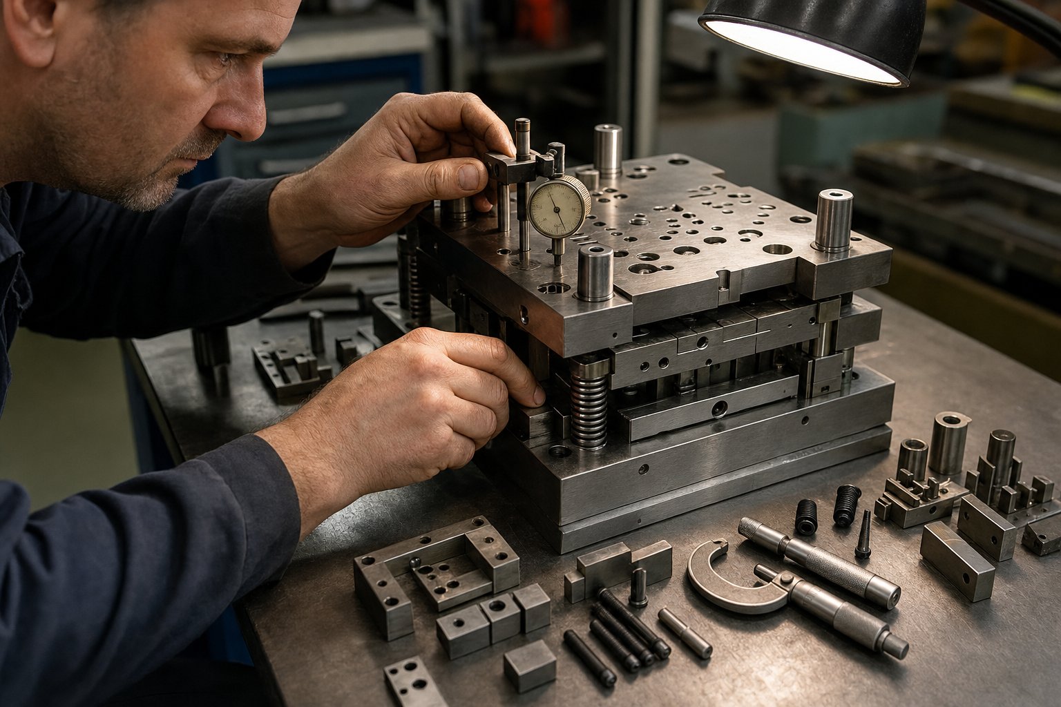
Sourcing Progressive Dies and Managing the Project Lifecycle
Confirming that progressive tooling fits your application is only the starting line. The real execution challenge lies in managing the journey from part concept to qualified production, and choosing the right progressive die manufacturers to partner with along the way. Get the lifecycle wrong and you absorb months of delays, costly rework, and dies that never quite hit the mark. Get it right and the tool delivers millions of consistent parts with minimal drama.
The Project Lifecycle From Design to Production
Every progressive die program follows a predictable arc, and knowing what to expect at each phase helps you ask better questions, catch problems early, and keep the timeline from drifting.
- Part design review and DFM feedback - Before any tooling work begins, experienced die engineers review your part drawing for manufacturability. They flag features that will drive unnecessary cost: overly tight tolerances on non-functional dimensions, bend radii that risk cracking, hole placements too close to forms. This is where progressive stamping die design starts, not with the tool itself, but with optimizing the part for the process. Expect 1 to 2 weeks of back-and-forth if your geometry is complex.
- Die design and simulation - The supplier creates the strip layout, sequences stations, and models the complete die in 3D CAD. For critical forming operations, FEA simulation predicts material flow, springback, and potential thinning before steel is ever cut. A thorough progressive die design phase typically runs 3 to 5 weeks and should produce a formal design review with your team before approval to build.
- Die construction - CNC machining, wire EDM, grinding, and heat treatment transform raw tool steel into finished die components. Assembly and bench fitting follow. This phase consumes 6 to 10 weeks depending on die complexity and supplier capacity.
- Tryout and sampling - The die goes into a press for initial runs. Engineers measure sample parts, adjust forming stations for springback, verify strip feeding, and iterate until parts meet print. Plan for 2 to 4 weeks, sometimes longer for multi-station tools with tight forming tolerances.
- Production qualification and ramp - Once samples pass inspection, a production trial at full speed validates SPC capability. First article inspection (FAI) documentation locks in the baseline. From here, you ramp to full volume.
At each gate, you should receive measurable deliverables: design review packages, simulation reports, sample parts with dimensional data, and capability studies. If a supplier cannot provide these, that is a red flag about their process maturity.
Evaluating Progressive Die Manufacturers for Your Application
Not all progressive tool and die shops deliver the same value. The gap between a supplier who simply machines steel and one who engineers a production solution shows up in die performance, maintenance costs, and ramp speed. When evaluating progressive die stamping services, use these criteria to separate strong partners from risky ones:
- High-volume progressive die capability with scalable production support - Suppliers like YICHEN specialize in progressive stamping dies engineered for efficient multi-station forming, tight repeatability, and scalable mass production, supporting production engineers and procurement teams who need a partner that bridges die sourcing and volume manufacturing under one roof.
- In-house engineering and die design capability - Look for dedicated design teams using current CAD/CAM platforms and forming simulation software. Outsourced design adds communication layers and slows iteration cycles.
- Toolroom capacity and equipment quality - CNC machining centers, wire EDM, precision grinding, and in-house heat treatment indicate a supplier who controls quality at every fabrication step rather than relying on subcontractors.
- Press tonnage range and tryout facilities - A manufacturer with on-site presses matching your production tonnage can tryout and validate the die under realistic conditions, catching problems that would otherwise surface only after the tool ships.
- Material and industry experience - A shop experienced in your specific material, whether stainless, copper, or high-strength steel, will anticipate forming challenges and specify appropriate insert materials and clearances from the start.
- Quality certifications and process documentation - ISO 9001 or IATF 16949 certification signals disciplined process control. Ask for evidence of SPC implementation, first article procedures, and traceability systems.
- After-sales support and maintenance service - Progressive stamping dies require ongoing sharpening, component replacement, and periodic refurbishment. Evaluate whether the supplier offers maintenance support, spare parts stocking, and responsive technical service after delivery.
- Scalability and flexibility - Your volumes may grow or your part design may evolve. A supplier capable of modifying existing dies, adding stations, or building follow-on tooling without starting from scratch provides long-term value.
When possible, visit the facility. Walk the toolroom floor, examine progressive dies in various stages of build, and ask to see sample parts from comparable programs. References from customers in your industry carry more weight than any brochure. A manufacturer who can show you a die they built five years ago still running at production speed tells you more about their engineering quality than any sales deck ever will.
Ultimately, sourcing progressive die stamping services is not a purchasing transaction. It is a technical partnership. The supplier's engineering judgment shapes your die design, their build quality determines your maintenance burden, and their process discipline dictates how quickly you reach stable production. Choosing on price alone almost always costs more in the long run than choosing on capability and then negotiating fair terms.
Frequently Asked Questions About Progressive Die and Stamping
1. What is the difference between a progressive die and a transfer die?
A progressive die keeps the workpiece attached to a carrier strip as it advances through multiple stations, separating it only at the final blanking station. A transfer die separates the part early and uses mechanical fingers or rails to move discrete blanks between stations. Transfer dies are preferred for very deep draws, parts larger than practical coil widths (around 24 inches), or geometries requiring tooling access to all edges. Progressive dies run faster (200-1,200+ SPM vs 20-80 SPM for transfer) and cost less per part at high volumes, but they impose size and draw-depth constraints that transfer tooling avoids.
2. How much does a progressive stamping die cost?
Progressive die cost depends on station count, forming complexity, insert material, tolerance requirements, and expected die life. Simple pierce-and-bend dies with 4-6 stations typically range from $10,000 to $25,000. Medium-complexity tooling with 8-14 stations falls between $25,000 and $60,000. High-complexity dies with deep draws, carbide inserts, or specialized sensors can exceed $60,000. Part design directly influences cost since every added feature requires an additional station, and tighter tolerances demand finer machining and more tryout iterations.
3. What volume justifies investing in progressive die tooling?
Most applications reach a clear ROI crossover at 50,000 to 100,000 annual units compared to alternatives like laser cutting or CNC punching. Ultra-simple parts may justify investment at 30,000 units, while complex parts with high per-piece alternative costs can break even sooner. The math is straightforward: divide your tooling investment by the per-part savings over alternative methods. Below the crossover volume, tooling amortization dominates per-part cost and makes simpler methods more economical.
4. What tolerances can progressive die stamping achieve?
Achievable tolerances vary by operation type. Piercing and blanking operations hold ±0.001 to ±0.003 inches, with ±0.0005 inches possible using precision tooling. Bending and forming typically achieve ±0.005 to ±0.015 inches due to springback variability. Coining operations deliver ±0.001 to ±0.002 inches by compressing material under high tonnage. Key factors affecting precision include die condition, material consistency within the coil lot, press deflection under load, thermal expansion during long runs, and pilot pin accuracy for strip registration.
5. How long does it take to build a progressive die from design to production?
A typical progressive die program runs 12 to 20 weeks from design kickoff to production-qualified parts. The timeline breaks down as follows: die design and engineering (3-5 weeks), material procurement (1-3 weeks, often overlapping), machining and heat treatment (5-8 weeks), assembly and fitting (1-2 weeks), tryout and iteration (2-4 weeks), and production qualification (1-2 weeks). Simpler tooling can compress to 8-10 weeks, while complex dies with tight forming tolerances may extend longer. Late-stage design changes after machining begins can add weeks and significant cost.


