


What Are Bypass Notches in Stamping Dies
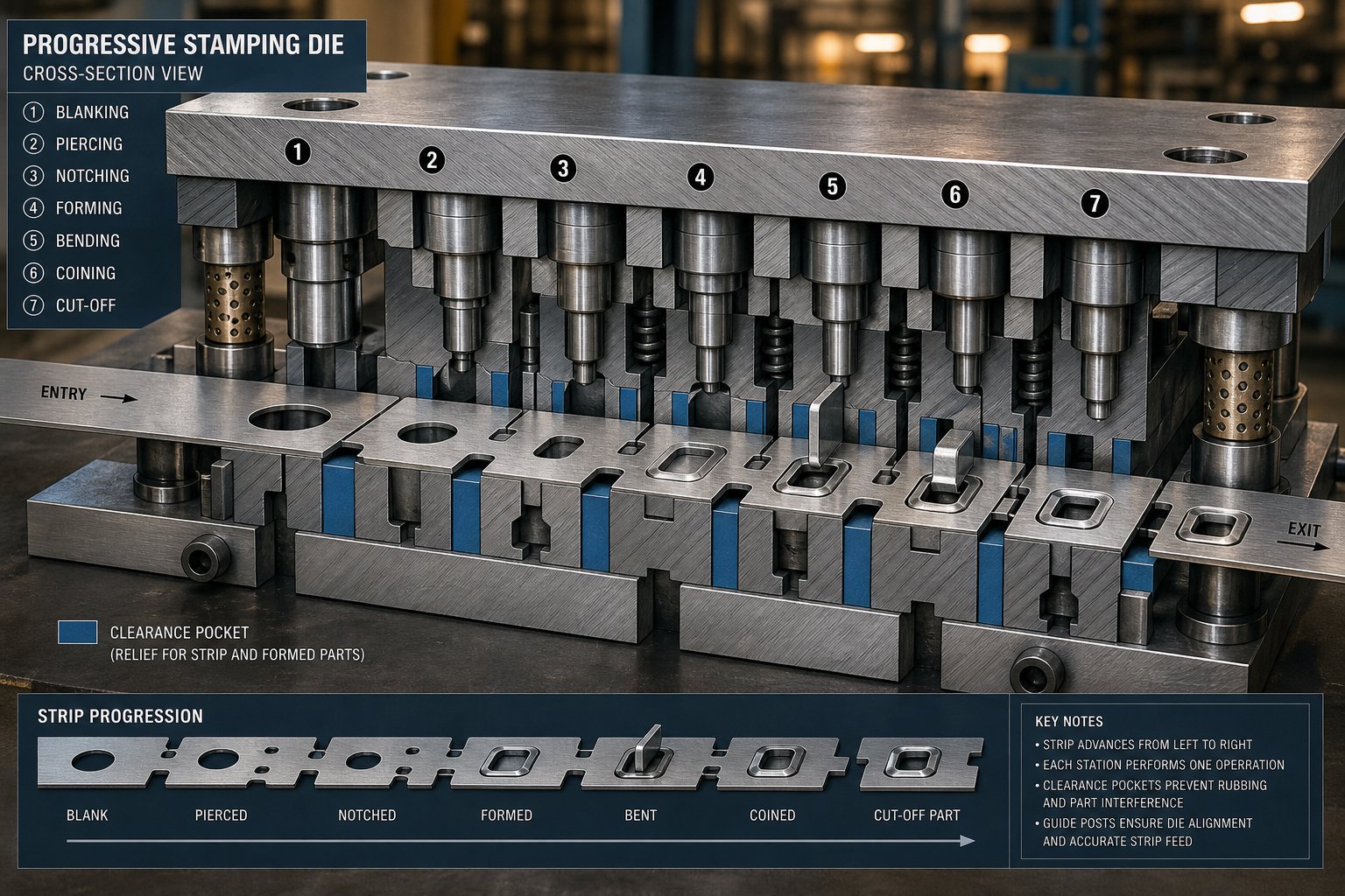
When a strip of sheet metal travels through a progressive die, every forming operation creates geometry that sticks up or down from the strip plane. Those protruding features need somewhere to go as the strip advances to the next station. That is precisely where bypass notches come in.
Technical Definition of Bypass Notches
A bypass notch is a relief cutout made in the strip stock - or a clearance pocket machined into the die steel - that allows previously formed features such as draws, lances, and embosses to pass over or through downstream die components without collision. The purpose of bypass notches in stamping dies is strictly about clearance: they prevent physical interference between three-dimensional geometry already stamped into the strip and the tooling that still needs to act on it.
This is not the same as general notching in metal forming. Standard notching operations cut material from the edge of a strip to create a desired profile or facilitate bending. Bypass notches, by contrast, serve no part-geometry purpose. They exist entirely to keep the strip moving freely through the die.
Within the die design hierarchy, bypass notches sit at the strip layout level - planned during the earliest stages of progressive die development alongside carrier design, pilot placement, and station sequencing. They are not an afterthought or a tryout fix. They are a deliberate engineering decision baked into the strip layout from day one.
Why Bypass Notches Matter in Progressive Die Stamping
Imagine a strip that has just had a small cup drawn at station three. That cup now protrudes below the strip plane. At station four, the strip must lower onto the die block for the next operation. Without clearance for that cup, it slams into solid tool steel. The result: a jammed strip, a damaged die, and production grinding to a halt.
Bypass notches in sheet metal forming solve this by removing just enough material - or providing just enough pocket depth in the die - so the formed feature clears every subsequent station during strip advancement. In a progressive die where the strip passes through dozens of stations sequentially, a single forming operation can require bypass clearance at every downstream location.
Bypass notches exist for one reason: to maintain uninterrupted strip progression through multi-station dies by preventing formed features from colliding with downstream tooling.
The bypass notches sheet metal forming purpose becomes even more critical at high press speeds. When a strip cycles at hundreds of strokes per minute, even a fraction of a millimeter of interference can cascade into catastrophic tool failure. Understanding exactly how these clearance features function during each stroke - and what happens when they are undersized or missing - separates reliable production tooling from chronic jam-prone dies.
Terminology Clarification for Notch Types in Die Design
The word "notch" gets used loosely on the shop floor. A die maker might call out a "notch" in a strip layout review, and three people at the table picture three different features. This ambiguity causes real confusion - especially for newer tool and die maker professionals trying to read legacy drawings or interpret strip layout intent. Bypass notches, pitch notches, relief notches, and trim notches all remove material from the strip, but they exist for entirely different reasons.
Understanding these distinctions matters because misidentifying a notch type during design review or maintenance can lead to incorrect modifications. Widening what you think is a bypass notch - when it is actually a pitch notch - could destroy strip registration and ruin every part that follows.
Bypass Notches vs Pitch Notches
Pitch notches (sometimes called French notches) control strip feed length and provide a solid first-hit stop during die setup. As Art Hedrick explains in The Fabricator, a pitch notch is a small section of material cut from one or both edges of the strip at the beginning stations of a progressive die. Its job is to prevent overfeeding, remove edge camber, and give the operator a precise reference for initial strip positioning so that pilots can locate the strip correctly.
Bypass notches, on the other hand, have nothing to do with feed control or strip registration. They provide clearance for formed geometry - draws, embosses, lances, or any feature protruding from the strip plane - so the strip can advance past downstream die stations without interference. A pitch notch asks: "How far has the strip traveled?" A bypass notch asks: "Can the formed feature clear the next die block?"
The confusion between these two is common because both appear as cutouts on the strip edge or interior, and both are planned during strip layout. But their design drivers are fundamentally different. Pitch notch geometry is driven by feed pitch and pilot location. Bypass notch geometry is driven by formed feature height and downstream die clearance.
Bypass Notches vs Relief Notches and Trim Notches
Relief notches address material stress, not physical clearance. When you bend sheet metal at a corner or along an intersecting edge, stress concentrations can cause tearing or cracking. A relief notch - typically a small cutout at the intersection of two bend lines - removes material from the stress zone so the part can form cleanly without splitting. You will find these in brake-formed parts just as often as in die-stamped ones.
Trim notches serve yet another purpose: scrap separation. They are cuts placed in the strip to facilitate clean part removal or slug shedding at the final stations. Without adequate trim notches, the part may not separate cleanly from the carrier, causing burrs, hangers, or scrap jams in the die.
Carrier notches are a related feature worth noting. These are cutouts specifically shaped to maintain the carrier strip's connection to each part blank while still allowing it to flex during feeding. They balance strip rigidity with the ability to absorb forming forces without buckling.
Every one of these terms appears in tooling references and shop conversation, sometimes interchangeably. For any die maker working on negative and positive bypass notches in a sheet metal stamping die, keeping the terminology straight prevents costly miscommunication during design, build, and maintenance.
| Notch Type | Primary Function | Typical Location in Strip | Design Driver |
|---|---|---|---|
| Bypass Notch | Clearance for formed features to pass downstream stations | Near formed geometry, carrier area, or interior of strip | Formed feature height vs. die block clearance |
| Pitch Notch | Strip feed control, first-hit stop, edge camber removal | One or both strip edges at beginning stations | Feed pitch, pilot location, setup registration |
| Relief Notch | Stress relief at bend line intersections to prevent tearing | Corners where two bends meet or at bend termination points | Material ductility, bend radius, and geometry intersection |
| Trim Notch | Scrap separation and clean part removal from carrier | At carrier-to-part connection points in final stations | Part outline, scrap path, and slug shedding requirements |
With these definitions separated, the next logical question is mechanical: how exactly does a bypass notch interact with the strip as it lifts, advances, and lowers during each press stroke? The answer lies in the sequence of positive and negative clearance events that happen every time the ram cycles.
How Bypass Notches Function During Strip Progression
Picture a coil of sheet metal feeding into a progressive die. With every press stroke, the strip advances exactly one pitch - one station-to-station distance - and a different operation acts on it: piercing at station one, notching at station two, forming at station three, drawing at station four, and trimming near the end. The strip remains connected by a carrier web throughout. As long as every feature stays within the strip plane, advancement is straightforward. The moment a forming or drawing operation pushes geometry above or below that plane, interference becomes inevitable at every station downstream.
This is where the bypass notch earns its place in the strip layout. It is planned specifically to handle the three-dimensional reality of a part that is partially formed but still traveling through a flat die environment.
Strip Advancement and Formed Feature Interference
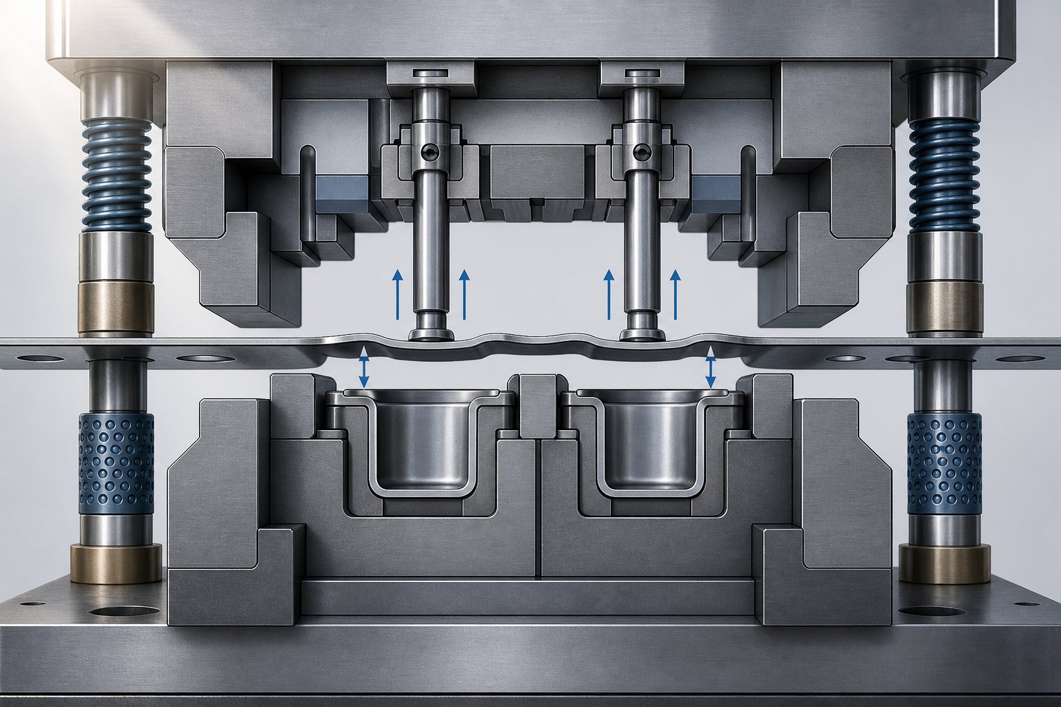
Each press stroke follows a precise mechanical rhythm. When the ram rises, stock lifters push the strip upward off the lower die surface - typically just enough to clear the die blocks and any locating features. The feeder then advances the strip exactly one pitch distance. Pilots enter their holes to register the strip into true position, the feeder releases, and the strip lowers back onto the die for the next operation.
Sounds simple when the strip is flat. But consider what happens after station three forms a downward-facing cup or lance. That feature now hangs below the strip plane. As the strip lifts and advances to station four, the cup needs to pass over the station-four die block without catching on it. If the lifter height does not provide enough vertical clearance - and in many cases it cannot without slowing the press - the cup drags across or slams into solid tool steel.
Bypass notches solve this by removing a window of material from the strip around the formed feature, or by providing a machined relief pocket in the die block itself. The formed geometry passes freely through the gap rather than colliding with tooling. In a die with twelve or more stations, a single draw formed at station four may require bypass clearance at stations five through eleven - each one carefully sized to accommodate the feature as it travels through the die.
Positive and Negative Bypass Notch Mechanics
Not all formed features protrude in the same direction, and not all bypass solutions are cut from the strip. This is where the distinction between negative and positive bypass notches in sheet metal stamping dies becomes critical.
A positive bypass notch is material removed from the strip itself. When a feature protrudes upward - an emboss, a lance tab, or the top of a drawn wall - it risks colliding with upper die components like stripper plates, pressure pads, or punch holders at downstream stations. Cutting away strip material adjacent to the upward feature gives it room to pass beneath those upper components without contact. The yielding force of the stripper spring would otherwise press the strip flat against geometry that physically cannot comply.
A negative bypass notch is a clearance pocket machined directly into the lower die steel. When a formed feature protrudes downward - a cup draw, a coined recess, or a downward lance - it needs somewhere to go as the strip lowers onto each subsequent die block. Rather than removing more strip material (which could weaken the carrier), the die designer machines a relief cavity into the die block at the exact location where the downward feature will sit.
Many parts require both types simultaneously. Imagine a part with an upward emboss and a downward cup at the same cross-section. As that section of strip advances, the emboss needs positive bypass clearance above while the cup needs a negative bypass pocket below. Negative and positive bypass notches in sheet metal forming stamping dies often coexist at the same station, each addressing a different protruding direction.
The complete bypass sequence during a single press cycle follows this order:
- The forming or drawing operation creates geometry that protrudes above or below the strip plane.
- The ram rises, and stock lifters raise the strip off the lower die surface.
- The feeder advances the strip one full pitch to the next station.
- The bypass notch (strip cutout or die pocket) allows the formed feature to clear the next station's die block, stripper, or upper tooling without interference.
- Pilots engage their holes to register the strip in true position.
- The strip lowers onto the die, with the formed feature resting inside the negative bypass pocket or passing freely through the positive bypass opening.
- The next operation executes on the properly registered strip.
This cycle repeats at every station downstream of the forming operation. Each bypass location must be individually sized based on the feature height, the available lift, and the geometry of the die components at that specific station. A bypass notch that provides adequate clearance at station five may be undersized at station eight if that station's die block sits higher or its stripper plate hangs lower.
The precision of this sequence explains why bypass notch planning cannot be deferred to tryout. Every clearance point must be anticipated during strip layout design - because once tool steel is hardened and assembled, adding bypass relief means disassembly, re-machining, and lost production time. The consequences of getting it wrong ripple far beyond a single jammed strip.
Consequences of Omitting or Undersizing Bypass Notches
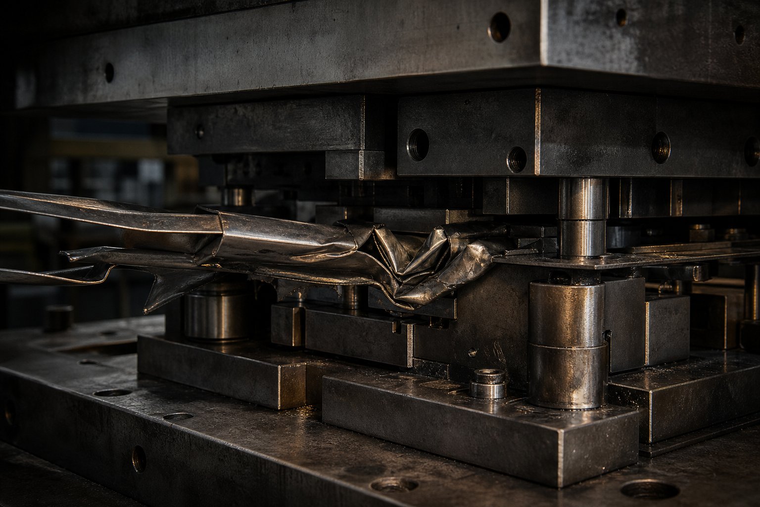
A strip jam does not announce itself politely. One stroke the press runs fine. The next, a formed feature catches a die block, the strip buckles, pilots shear, and the operator hears the unmistakable crunch of steel colliding with steel. What follows is not just a single bad part - it is a cascade of damage that can take a die out of production for days.
When bypass clearance is missing or undersized, every press cycle becomes a potential collision event. The formed geometry protruding from the strip has no room to pass, so it forces its way through - or it does not pass at all. Either outcome costs time, tooling, and parts.
Strip Jamming and Die Damage from Missing Bypass Clearance
The failure sequence is mechanical and predictable. A downward-protruding feature - a cup draw, a coined pocket, a lance tab - drops onto a die block that has no relief pocket. The strip cannot lower into position. The feeder, still trying to advance material, pushes additional stock into a strip that is no longer moving freely. Material buckles between stations, compressing into the space between lifters and die surfaces.
That buckling does not stay local. It propagates upstream, displacing the strip at prior stations where pilots are still trying to register position. Pilot pins, designed to enter prepierced holes with just 0.002 to 0.003 inches of clearance, encounter a strip that has shifted laterally or lifted off the die face. The pilot either bends or shears entirely. As Art Hedrick notes, if pilots cannot locate the strip accurately before the pressure pad clamps down, every subsequent operation lands in the wrong position.
The damage compounds from there. Die blocks can crack where a formed feature impacts a sharp internal corner of the tool steel. Punches at adjacent stations may chip because the misregistered strip presents material at an unexpected angle, creating uneven shearing loads. Guide rails score as the buckled strip drags across their hardened surfaces. In severe cases, the stripper plate distorts from absorbing impact loads it was never designed to handle.
The material itself suffers deformation hardening at the collision zone. Strip stock that repeatedly gets forced past an obstruction develops work hardened edges and localized yield stress increases in those areas. This makes the strip stiffer and less predictable at downstream forming stations - even after the immediate jam is cleared and production restarts.
Part Quality Defects Linked to Inadequate Bypass Design
Not every bypass failure causes a hard jam. Sometimes the interference is marginal - the formed feature barely grazes the die block, or drags across it just enough to keep the strip moving. These near-miss conditions are arguably worse than a full stop, because they produce defective parts intermittently rather than shutting the die down immediately.
Here is what marginal bypass clearance does to part quality. The strip drags across a die surface every few strokes, scratching the underside of formed features. Dimensional variation creeps in as the strip registers slightly off-position - not enough to shear a pilot, but enough to shift hole locations or bend lines by tenths of a millimeter. Work hardening accumulates at the contact edges where the strip repeatedly scrapes past die steel, changing the material's local mechanical properties and affecting subsequent forming behavior.
Bypass notches and burr formation in stamping are directly connected. When the strip distorts from dragging or partial buckling, it presents to cutting stations at an inconsistent angle or with uneven clamping. Punch-to-die clearance - carefully calculated for flat, properly registered material - becomes effectively asymmetric. One side of the cut shears cleanly while the other tears, producing burrs that exceed specification. The yield stress of the work hardened zone around the bypass interference point may differ significantly from the parent material, further destabilizing the cut.
These quality issues share a frustrating characteristic: intermittency. They appear in a few parts per hundred, not every part. Operators see a burr spike on one run but not the next. Dimensional checks pass for an hour, then drift out of tolerance for twenty parts before returning to spec. Root cause analysis often chases lubrication, punch wear, or material batch variation - all reasonable suspects - while the real culprit is a bypass notch that provides clearance 90% of the time but allows interference on every tenth stroke due to strip lift inconsistency or thermal expansion during long runs.
The full list of failure modes tied to inadequate bypass design includes:
- Strip jam - complete stoppage requiring manual clearing and die inspection
- Pilot shearing - loss of strip registration accuracy at all stations
- Die block cracking - expensive repair or replacement of hardened tool steel
- Part deformation - formed features crushed or displaced by collision forces
- Burr formation - asymmetric cutting from misregistered or distorted strip
- Dimensional drift - progressive loss of positional accuracy across stations
- Increased scrap rate - parts failing inspection due to surface, dimensional, or form defects
Every one of these outcomes traces back to the same root cause: a formed feature that had nowhere to go. The fix is almost always cheaper to implement during strip layout design than to troubleshoot on the press floor - which raises the question of how different die types and material properties influence the bypass clearance decision in the first place.
Bypass Notch Requirements Across Different Die Types
Not every stamping die moves material the same way. The method a die uses to transport the workpiece between operations fundamentally changes whether bypass notches are needed, where they go, and how complex their design becomes. A tool and die professional working across different die platforms will encounter wildly different bypass requirements depending on whether the application calls for a progressive, transfer, or compound die setup.
The differences come down to one question: does the strip stay connected and travel through every station sequentially, or is the workpiece separated early and handled independently? That answer dictates the entire bypass clearance strategy.
Bypass Notches in Progressive Dies
Progressive dies demand the most extensive bypass notch planning of any die type. The reason is structural. In a progressive die, the workpiece stays attached to the metal strip from start to finish - it is only separated at the final station. Every forming operation that occurs at station three, four, or five creates geometry that must pass through stations six, seven, eight, and beyond as the strip advances one pitch at a time.
This creates a compounding effect. A single draw at station four does not just need clearance at station five. It needs clearance at every downstream station the strip travels through before the part is cut free. In a twenty-station die, that single forming operation could require bypass relief at fifteen or more locations. Add a second forming station at station seven, and the bypass plan doubles in complexity - because now two features, at different heights and positions, both need clearance at all stations beyond their respective forming points.
Progressive dies also run at high speeds, often hundreds of strokes per minute. The strip lifts, advances, and lowers in milliseconds. There is no time for the operator to adjust or correct a marginal clearance issue. Either the bypass notch provides enough room for the formed feature to pass cleanly, or it does not. At 400 strokes per minute, a half-millimeter of insufficient clearance produces 400 collisions per minute - and a destroyed die in seconds.
This is why experienced tool and die designers spend significant time during strip layout planning to map every formed feature against every downstream station. Bypass notch locations, sizes, and types (positive strip cutouts versus negative die pockets) are determined before any steel is cut. The strip layout is essentially a bypass clearance plan as much as it is a part production sequence.
Bypass Considerations in Transfer and Compound Dies
Transfer dies handle material differently. Instead of keeping the workpiece attached to a continuous strip, transfer die stamping separates the workpiece from the metal strip at the beginning of the process. Individual blanks are then moved between stations by mechanical transfer mechanisms - grippers, fingers, or rails that physically pick up each piece and place it in the next die station.
Does this eliminate bypass notch needs? In the strip sense, yes. There is no continuous carrier traveling through multiple stations, so there are no bypass notches cut into strip stock. But the underlying clearance problem does not vanish - it just changes form. When a transfer mechanism places a partially formed blank into the next station, any geometry protruding from that blank still needs somewhere to go. The die block at that station must have relief pockets machined into it so the blank can seat properly without formed features bottoming out on tool steel.
Think of it as the same engineering problem solved at a different location. In progressive dies, bypass clearance lives in the strip and in the die. In transfer dies, it lives entirely in the die components. The tool and die builder machines clearance cavities into each station's die block to accommodate whatever geometry arrived from the prior operation. Transfer dies also benefit from the fact that each station is mechanically independent - the blank is lifted clear of all tooling during transfer, providing inherent vertical clearance that progressive strips cannot achieve without lifters.
Compound dies occupy the opposite end of the spectrum. A compound die performs multiple operations - cutting, piercing, forming - in a single press stroke at a single station. The part is completed and ejected in one hit. There is no strip progression, no multi-station travel, and no downstream interference to worry about. Bypass notches are simply not relevant. The part never needs to pass over another die block because it never moves to another station. Operations like hydroforming and spin forming similarly produce parts in single-stage or enclosed-die environments where strip progression does not apply.
The table below summarizes how bypass requirements differ across these three die types:
| Die Type | Strip Travel Method | Bypass Notch Relevance | Alternative Clearance Methods |
|---|---|---|---|
| Progressive Die | Continuous strip advances one pitch per stroke through all stations | High - required at every downstream station after each forming operation | Increased strip lift height, part rotation in layout, cam-driven variable lifters |
| Transfer Die | Individual blanks moved between independent stations by mechanical grippers | None in the strip - but equivalent clearance is machined into die blocks | Relief pockets in die steel, nest geometry designed around formed features, gripper clearance zones |
| Compound Die | No strip travel - all operations occur in one stroke at one station | Not applicable - no multi-station progression exists | None needed - part is completed and ejected in a single hit |
For manufacturers evaluating which die type suits a particular part, bypass complexity is a real cost factor. A part with deep draws and multiple embosses may be straightforward to produce in a transfer die where each station simply machines its own relief pocket. That same part in a progressive die could require dozens of bypass notches across the strip layout, weakening the carrier and demanding careful balance between clearance and strip rigidity. The die type decision shapes the bypass strategy - and the bypass strategy, in turn, influences how material properties and thickness interact with the clearance design.
Material and Thickness Factors in Bypass Notch Design
A bypass notch sized perfectly for 1.0 mm mild steel will fail catastrophically on 1.5 mm dual-phase 980. The material running through your progressive die does not just affect forming forces and punch wear - it directly determines how tall formed features protrude from the strip plane, how much they spring back after forming, and how the strip itself responds to having material removed. Every bypass clearance decision is, at its core, a metallurgical decision.
Two strips with identical part geometry but different materials can require radically different bypass notch designs. Understanding why comes down to three interacting variables: thickness, yield strength, and elastic modulus.
How Material Thickness and Strength Affect Bypass Clearance
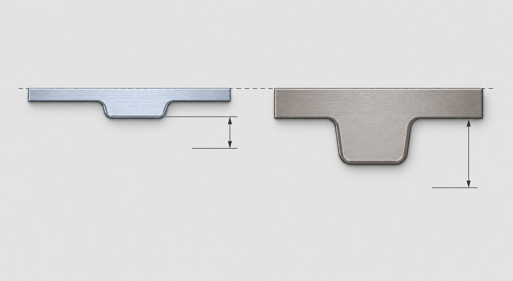
Material thickness is the most direct driver of bypass clearance requirements. When a forming punch draws a cup or pushes an emboss into the strip, the height of that feature is a function of the material thickness and the draw geometry. Thicker material produces taller formed features - a 2.0 mm strip drawn into the same punch geometry as a 1.0 mm strip will produce a feature with greater wall height and deeper protrusion below the strip plane. That deeper protrusion demands a correspondingly deeper bypass relief pocket in downstream die blocks.
The relationship is roughly proportional but not linear. Thicker materials also resist wrinkling and buckling better during forming, which means they tend to produce cleaner, more predictable feature heights. Thinner materials may produce slightly inconsistent feature depths due to localized stretching or material thinning at draw radii - and inconsistency in feature height means your bypass clearance must account for the worst case, not the average.
Yield strength introduces a second layer of complexity. Higher yield strength materials - advanced high-strength steels (AHSS) like DP590, DP980, and martensitic grades - exhibit significantly more springback after forming. As Art Hedrick explains, if you do not impart enough strain to exceed the material's yield point during forming, elastic recovery occurs. The formed feature partially springs back toward its original flat state.
What does springback mean for bypass notch design? It means the formed feature may not seat fully into its intended depth. A cup that was designed to draw 8 mm deep might only achieve 7.2 mm of permanent deformation in a high-strength grade, with the remaining 0.8 mm recovering elastically. That partially-sprung feature sits higher in the strip plane than intended - and the bypass notch that was sized for a fully-seated 8 mm cup now has less clearance margin than planned.
When evaluating yield strength vs tensile strength for bypass planning, the yield strength is the more relevant value. Tensile strength tells you when the material fractures, but yield strength defines the threshold where permanent plastic deformation begins. Materials with high yield-to-tensile ratios - common in AHSS grades where springback magnitudes grow proportionally as tensile strengths reach 980 MPa and above - store more elastic energy during forming and release it as springback. This directly increases the effective protrusion height that bypass notches must accommodate.
Softer materials present the opposite concern. Aluminum alloys, copper, and low-carbon deep-drawing steels have a lower elastic modulus compared to high-strength grades. The elastic modulus metals exhibit determines their stiffness - aluminum's modulus is roughly one-third that of steel. A lower modulus means the strip is more flexible and more susceptible to localized deformation from forces that harder materials would shrug off. If a bypass notch is placed too close to a formed feature in a soft aluminum strip, the thin web of material between the notch and the feature may deflect or permanently deform under the stripping forces during each press stroke. The feature geometry distorts, the part fails inspection, and the root cause is not the forming station at all - it is the bypass notch placement.
Strip Width and Tensile Properties in Bypass Planning
Strip width creates a hard constraint on how much material you can remove for bypass clearance without compromising the carrier. In a wide strip with generous carrier margins, bypass notches can be sized liberally - there is plenty of remaining cross-section to maintain rigidity during feeding. Narrow carrier strips offer no such luxury.
Consider a strip layout where the carrier web is only 8 mm wide on each side. Every bypass notch cut into that carrier reduces its effective cross-section. Remove too much, and the carrier can no longer resist the feeding forces without bending or buckling. As carrier design research shows, the carrier must remain strong enough to resist roughly 10% of the part weight multiplied by the number of progressions. Multiple bypass notches across consecutive stations create cumulative weakening that can push the carrier below its minimum rigidity threshold.
This tradeoff is especially acute in thin, high-strength materials. The strip is already thinner - meaning less moment of inertia for the carrier cross-section - and the yield strain steel exhibits at high-strength grades is narrow, leaving little margin between elastic flexing and permanent carrier deformation. A carrier that flexes elastically during feeding in mild steel may plastically bend in the same geometry when running AHSS because the yield strain window is tighter relative to the imposed stress.
Strain hardening and work hardening near bypass notch edges introduce another failure mechanism that shows up primarily in high-cycle applications. Every time the strip is punched to create a bypass notch, the shear zone at the cut edge undergoes localized cold work. That narrow band of work-hardened material becomes harder but more brittle than the parent strip. In a die running millions of cycles, these hardened edges can become crack initiation points - especially if the bypass notch geometry includes sharp internal corners that concentrate stress.
The practical implication: bypass notch corner radii matter more in high-strength materials than in mild steel. A sharp 90-degree internal corner that survives indefinitely in a low-carbon strip may initiate a fatigue crack within 500,000 strokes in a DP780 strip because the work-hardened edge has less ductility to absorb cyclic strain. Designers working with AHSS should specify generous radii at all bypass notch corners and orient the notch geometry to minimize stress concentrators aligned with the strip feed direction.
All of these material factors - thickness driving feature height, yield strength driving springback margin, elastic modulus driving strip stiffness, and work hardening driving edge durability - feed into a single sizing decision for each bypass notch location. The challenge is that they interact. A thicker, stronger material produces taller features (more clearance needed) while simultaneously limiting how much carrier material you can safely remove (less clearance available). Resolving that tension requires judgment, simulation, or both - and it raises the practical question of when bypass notches are the right solution versus when alternative clearance methods make more engineering sense.
When to Use Bypass Notches vs Alternative Clearance Methods
Bypass notches are not the only way to keep a formed feature from colliding with downstream tooling. They are the most common solution in progressive dies, but they carry a cost: every notch weakens the carrier strip, every cut requires a punch and die component to maintain, and every removed section is material that can no longer support the strip during feeding. Experienced die designers treat bypass notches as one tool in a clearance toolkit - not as the automatic default for every interference point.
The real question is not "do I need clearance?" That answer is always yes when geometry protrudes from the strip plane. The question is: what is the best way to achieve that clearance for this specific part, this material, and this production requirement?
Decision Tree for Bypass Notch Necessity
Working through bypass clearance decisions follows a logical sequence. At each station in the strip layout, you evaluate whether the strip can advance cleanly - and if it cannot, which solution offers the best tradeoff between die complexity, press speed, carrier integrity, and material usage.
- Identify every forming operation in the strip layout that creates geometry protruding above or below the strip plane. This includes draws, embosses, lances, coined features, and extruded holes.
- For each formed feature, measure the protrusion height - the distance the feature extends beyond the strip surface. Account for springback if working with high-strength materials.
- Determine the available strip lift at each downstream station. This is the vertical distance stock lifters raise the strip above the lower die surface during feeding.
- Compare protrusion height against available lift minus die clearance. If the formed feature height exceeds the net clearance (lift height minus the height of any die components the strip must pass over), interference will occur.
- If interference exists, evaluate whether increased lift can solve the problem without a bypass notch. If the required additional lift is modest - a few millimeters - increasing lifter travel may be viable.
- If increased lift introduces unacceptable speed penalties or lifter wear, a bypass notch (strip cutout or die pocket) becomes the appropriate solution.
- If part rotation or reorientation within the strip layout eliminates the interference entirely, redesign the layout before committing to bypass notches.
This sequence is not purely theoretical. It reflects the iterative process that plays out during strip layout development, often supported by material nesting software for length of material utilization analysis. The software helps visualize how part orientation, carrier width, and bypass notch placement interact with overall strip yield - because rotating a part to avoid bypass may consume more material per piece, shifting cost from tooling complexity to raw material waste.
The critical threshold in step four deserves emphasis. If the formed feature height exceeds available strip lift minus die clearance, a bypass notch is mandatory. No amount of lifter adjustment, timing optimization, or press tuning will change the physics. The feature either clears the die block, or it collides. In borderline cases - where the feature barely exceeds available clearance - designers often add a bypass notch anyway as insurance against thermal expansion during long production runs, strip thickness variation within coil tolerance, and lifter wear that gradually reduces effective lift height over the die's service life.
Alternatives to Bypass Notches and Their Tradeoffs
When interference exists but bypass notches carry unacceptable consequences - weakened carrier, compromised strip rigidity, or insufficient material around pilot holes - three primary alternatives apply. Each solves the clearance problem but introduces its own cost.
Increasing Strip Lift Height
The simplest alternative: raise the strip higher during feeding so formed features clear downstream die blocks without any material removal. Stock lifters - whether spring-driven pins, bar lifters, or cam-actuated rails - can be specified with greater travel to achieve additional clearance.
The penalty is press speed. Higher lift means the strip travels a greater vertical distance each stroke cycle. The lifters must raise further, the strip must stabilize at the higher elevation before feeding, and it must lower a greater distance before pilots can engage. At high stroke rates, excessive lift introduces strip bounce and vibration that degrade feed accuracy. An inductive proximity sensor monitoring strip position at the feed line may confirm that the strip is settling consistently at higher lift, but the mechanical reality is that every millimeter of additional lift subtracts strokes per minute from your production rate.
Higher lift also accelerates lifter wear. Spring-loaded lifters cycling through greater deflection fatigue faster. Cam-driven lifters experience more contact wear on their actuation surfaces. Over a die's production life of millions of strokes, the maintenance cost of higher-travel lifters can exceed the tooling cost of adding bypass notches in the first place.
Rotating Part Orientation in the Strip Layout
Sometimes the interference exists only because of how the part is oriented relative to the strip feed direction. A formed feature protruding downward may collide with a die block directly in the feed path - but if the part is rotated 90 or 180 degrees in the layout, that same feature passes through an area where the die block is lower or absent entirely.
Part rotation is elegant when it works. It eliminates the interference without weakening the strip or slowing the press. But it often increases material consumption. A part oriented for minimum strip width may no longer nest efficiently after rotation. The strip becomes wider, the material cost per part rises, and scrap rates increase. For high-volume production where material cost dominates, this tradeoff may not pencil out - even though the tooling is simpler.
Rotation can also introduce new forming challenges. A part oriented at a different angle relative to the rolling direction may exhibit different springback behavior, anisotropic stretch characteristics, or grain-direction splitting tendencies that did not exist in the original orientation.
Cam-Driven Variable Lifters
Standard stock lifters raise the strip to a uniform height at every station. Cam-driven variable lifters allow different lift heights at different stations - higher where deep draws need to clear, lower where flat geometry needs minimal elevation. This selective approach provides bypass clearance only where needed without imposing a global lift penalty across the entire die.
The cost is mechanical complexity. Cam lifters require precision-ground cam surfaces, hardened followers, and tight timing coordination with the press stroke. They are typically cut using EDM wire machining to achieve the profile accuracy these cam surfaces demand. They add components to the die, increase maintenance points, and require more careful setup. In dies where only one or two stations need additional clearance, cam lifters can be an efficient solution. In dies with interference at ten or more stations, the cumulative cam complexity may outweigh the simplicity of cutting bypass notches into the strip.
Experienced die designers evaluate all of these alternatives during strip layout development - before any tool steel is ordered. The decision often comes down to a cost-benefit analysis specific to the application: production volume, material cost sensitivity, press speed requirements, and die maintenance budget. For complex progressive dies where these tradeoffs multiply across dozens of stations, collaborative design support from tooling specialists can make the difference between an optimized solution and an expensive compromise. Teams navigating intricate bypass decisions - particularly for design-heavy applications involving die structure, lifters, and material flow optimization - can find value in working with partners like YICHEN's custom stamping die solutions, where experienced tooling engineers contribute to these critical layout decisions early in the design process.
The clearance method you choose at each station shapes the entire downstream design. But regardless of whether you use a bypass notch, increased lift, part rotation, or a cam system, the notch locations that do make it into the strip layout still need precise placement and sizing - and those decisions follow their own set of engineering rules that balance strip integrity against clearance margin.
Best Practices for Bypass Notch Placement and Sizing
Choosing to add a bypass notch is only half the engineering problem. Where you place it, how large you make it, and how it interacts with every other strip feature - pilots, lifters, carriers, and adjacent stations - determines whether that notch actually solves the clearance problem or creates three new ones. A bypass notch in the wrong location can destroy strip registration just as effectively as having no bypass at all.
The placement and sizing decisions are tightly coupled. A notch positioned closer to the formed feature can be smaller (because the feature passes through the widest part of the relief). A notch positioned farther away must be larger to accommodate the angular path the feature traces as the strip lifts and advances. Every millimeter of position shift changes the required size - and every millimeter of size change affects carrier strength. Getting this right demands a systematic approach.
Bypass Notch Placement Rules and Strip Layout Integration
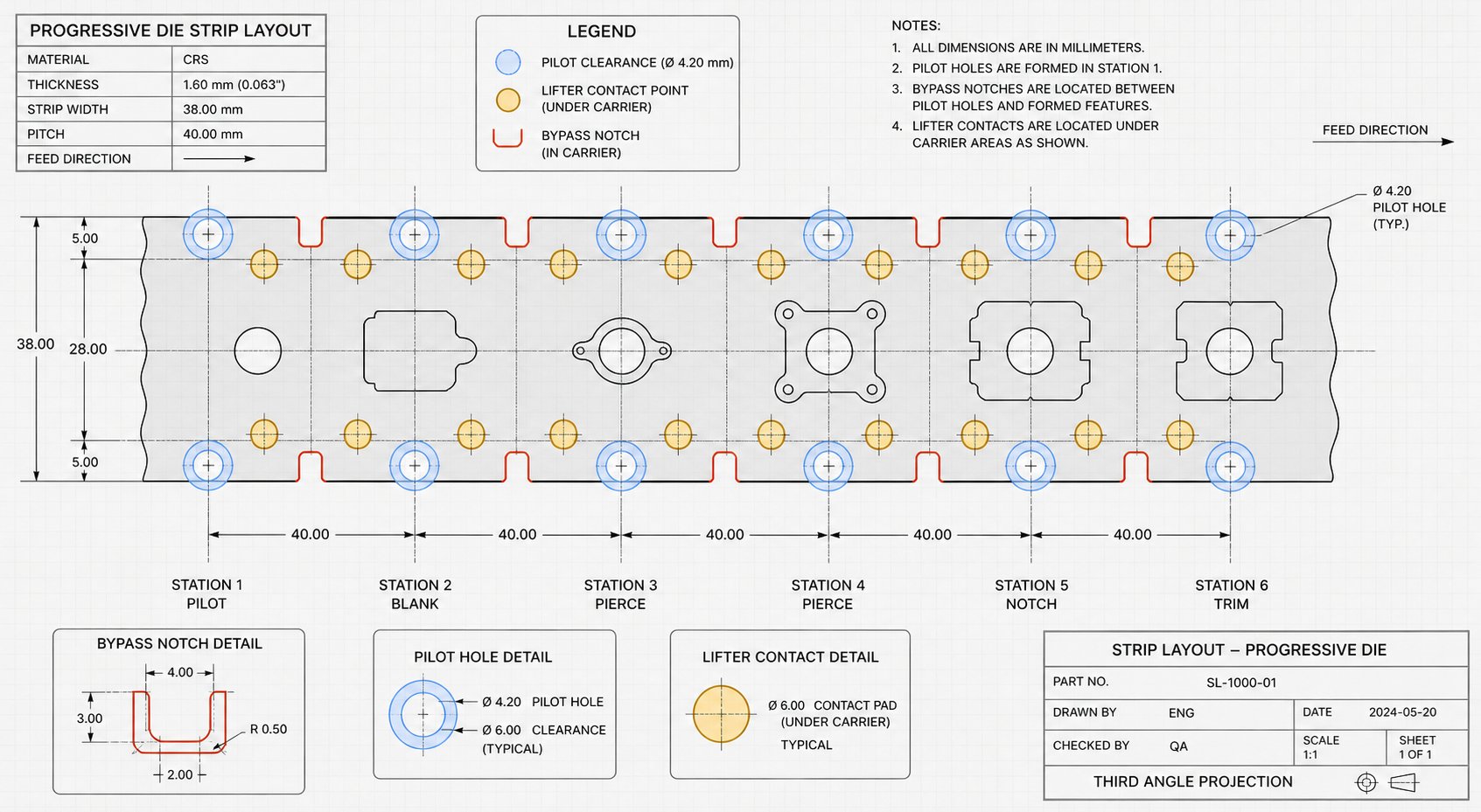
Bypass notch placement does not happen in isolation. The strip layout is a crowded neighborhood: pilot holes need unobstructed material for registration, lifters need solid contact surfaces to raise the strip evenly, and the carrier web needs continuous cross-section to resist feeding forces. A bypass notch that overlaps any of these zones creates a conflict worse than the original interference problem.
Here are the core placement principles that experienced die designers follow:
- Position bypass notches as close to the formed feature as material integrity allows. Closer placement means less required notch width because the feature passes through the notch at its narrowest point during strip advancement.
- Maintain minimum web distance between the bypass notch edge and any pilot hole. If the notch encroaches on pilot material, the thin remaining web deflects under pilot entry force, destroying registration accuracy. A general guideline is to keep at least 1.5 times material thickness as a minimum web between notch edge and pilot hole edge.
- Never place a bypass notch directly beneath a stock lifter contact point. Lifters push upward against the strip surface - if they contact a notched area, the strip either fails to lift evenly or the lifter pin drops through the opening. Map all lifter positions onto the strip layout before finalizing notch locations.
- Orient notch geometry to minimize stress concentration. Use generous internal radii rather than sharp corners, especially in high-strength materials where the yield stress of steel at the cut edge is elevated from shearing. A radius of at least one material thickness at internal corners significantly extends carrier fatigue life.
- Account for cumulative strip weakening when multiple bypass notches exist across consecutive stations. Each notch reduces carrier cross-section. Three notches in five stations can reduce the effective carrier moment of inertia by 40% or more, pushing the remaining material past the yield limit of steel under normal feeding loads.
- Stagger bypass notch locations between left and right carriers where possible. Symmetric notching at the same strip position creates a uniform weak point - staggering distributes the stress reduction across different feed positions and maintains more consistent strip rigidity.
- Verify that bypass notch edges do not coincide with bend lines or forming zones at adjacent stations. A notch edge landing on a bend line creates a stress riser that can initiate cracking during forming.
One detail that often gets overlooked: bypass notches cut at early stations travel through every subsequent station. A notch created at station two passes through stations three, four, five, and onward. At each of those downstream locations, the notch must not interfere with lifters, pilots, or clamping surfaces. This means placement validation is not just about the station where the notch is cut - it requires checking the notch footprint against every station it will ever pass through.
As practical stamping die design references confirm, a notch that looks harmless in CAD may become a feeding problem when the press runs at production speed. Sharp inner corners increase cracking risk, incorrect positions cause station interference, and oversized notches weaken carriers to the point of instability.
Sizing Guidelines and Connection to Strip Lift Requirements
Bypass notch sizing is a direct function of two variables: the protrusion height of the formed feature and the available strip lift at each downstream station. The relationship between these two values determines how wide and deep the notch must be to provide adequate clearance.
Think of it geometrically. When the strip lifts and advances, the formed feature traces an arc through space - up from the lower die surface, forward one pitch, then down onto the next die block. The bypass notch must be large enough to accommodate that feature at every point along its travel arc at each station. If the strip lift is high, the feature rises well above the die surface and the notch can be narrower because the feature clears most obstructions vertically. If the strip lift is low, the feature stays closer to the die surface during advancement and the notch must be wider to ensure horizontal clearance.
This inverse relationship is the key design lever: proper bypass notch sizing can reduce required strip lift height. A wider notch provides more horizontal clearance, meaning the feature does not need to rise as high to clear the die block. Lower lift translates directly to faster press cycle speeds and reduced lifter wear - a measurable productivity benefit. In high-volume applications running millions of strokes, even a 2 mm reduction in lift height can add meaningful strokes per minute to the production rate.
But the tradeoff is real. A larger bypass notch removes more carrier material. At some point, the carrier cross-section drops below the minimum rigidity threshold - the point where feeding forces exceed what the remaining material can resist without permanent deformation. For any given strip, there is an optimal notch size that balances clearance against carrier strength. Calculating that optimum requires knowing the yield strength of steel you are running (because that defines the carrier's load-bearing capacity), the steel modulus of elasticity (because that determines how much the carrier flexes elastically before yielding), and the feeding force applied by the press feed mechanism.
A practical sizing approach works as follows. Start with the minimum notch size that provides clearance at maximum strip lift. Then evaluate whether reducing lift height - and correspondingly increasing notch size - improves net productivity without compromising carrier integrity. The yield point for steel in the carrier section sets the hard limit: once the bending stress from feeding forces reaches that threshold, the carrier permanently deforms and feeding accuracy degrades.
For materials where the yield strength and yield point are close together (most engineering steels), the safety margin is straightforward to calculate. For materials with a gradual yield transition - like many aluminum alloys or work-hardened grades where yield strength yield stress values differ depending on offset definition - designers should use conservative assumptions and validate with tryout data.
Several additional sizing factors deserve attention in practice:
- Add clearance margin for thermal expansion during long production runs. Die steel and strip material expand at different rates - what clears cold may interfere after an hour of continuous stamping.
- Account for material thickness tolerance. A coil at the upper end of its thickness specification produces taller formed features than nominal. Size bypass notches for maximum material thickness, not nominal.
- Include allowance for lifter wear over the die's service life. As lifters lose travel from fatigue or surface wear, effective lift decreases. A notch sized with zero margin at initial lifter travel will eventually cause interference as the die ages.
- Consider the cumulative effect of strip stretch. In long progressive dies, slight strip elongation under feeding tension can shift bypass notch positions relative to die features by tenths of a millimeter - enough to reduce effective clearance at the final stations.
Comprehensive bypass notch design does not happen in a vacuum. It requires close coordination between strip layout planning - where notch locations and sizes are determined - die structure engineering - where negative bypass pockets are machined into die blocks - and tryout validation - where real-world feeding confirms that the clearances work under production conditions. Missing any one of these coordination points risks discovering interference problems on the press floor, where fixes cost ten times what they would have during design.
For tooling teams working on complex progressive dies where bypass notch optimization intersects with die structure, lifters, burr control, clearance, and material flow, YICHEN's custom stamping die solutions connect engineers to collaborative design support that addresses these interdependent decisions as a system rather than isolated variables.
The bypass notch - small on the drawing, critical in production - ultimately represents the intersection of every major progressive die design discipline: strip layout geometry, material science, mechanical dynamics, and production economics. Getting placement and sizing right means fewer jams, longer die life, faster cycle times, and consistent part quality from the first stroke to the millionth.
Frequently Asked Questions About Bypass Notches in Stamping Dies
1. What is the difference between a bypass notch and a pitch notch in a progressive die?
A pitch notch controls strip feed length and provides a first-hit stop for operator setup, ensuring pilot pins register the strip correctly. A bypass notch provides physical clearance so formed features like draws, embosses, or lances can pass over downstream die blocks without collision. Pitch notch geometry is driven by feed distance and pilot location, while bypass notch geometry is driven by formed feature height and the clearance available at each downstream station. Confusing the two during maintenance or modification can lead to misregistration or strip jamming.
2. What happens if bypass notches are missing or undersized in a stamping die?
Without adequate bypass clearance, formed features collide with downstream die components during strip advancement. This triggers a failure cascade that includes strip jamming, pilot pin shearing, die block cracking, surface scratching on parts, burr formation from misregistered cutting, and progressive dimensional drift. Marginal interference is particularly problematic because it produces intermittent defects that are difficult to trace back to bypass clearance as the root cause, often mimicking issues like punch wear or material variation.
3. Do transfer dies and compound dies require bypass notches?
Compound dies do not require bypass notches because all operations occur in a single stroke at one station with no strip progression. Transfer dies eliminate strip-based bypass notches since individual blanks are moved between stations by mechanical grippers. However, transfer dies still need equivalent clearance machined directly into die blocks as relief pockets so partially formed blanks can seat properly at each station without formed features bottoming out on tool steel.
4. How does material thickness affect bypass notch design?
Thicker material produces taller formed features that protrude further from the strip plane, requiring deeper bypass relief pockets or wider strip cutouts. High-strength steels add complexity because their greater springback means formed features may not seat to full design depth, effectively increasing protrusion height beyond what nominal geometry predicts. Softer materials like aluminum require careful notch placement because their lower elastic modulus makes the remaining strip web more susceptible to deflection under stripping forces. Designers must size bypass notches for worst-case material thickness within coil tolerance.
5. What are the alternatives to bypass notches for clearance in progressive dies?
Three primary alternatives exist. Increasing strip lift height raises the strip higher during feeding so features clear die blocks vertically, but this reduces press speed and accelerates lifter wear. Rotating part orientation in the strip layout can eliminate interference entirely, though it often increases material consumption and may introduce anisotropic forming challenges. Cam-driven variable lifters provide selective lift at specific stations without a global speed penalty, but add mechanical complexity and maintenance points. Experienced tooling engineers like those at YICHEN (yichen-group.com/stamping-die/) evaluate all options during strip layout development to find the optimal balance for each application.


