


What Makes Progressive Die Stamping Essential for Aerospace Manufacturing
When a single bracket failure can ground a fleet, part-to-part consistency stops being a manufacturing metric and becomes a safety imperative. That reality is exactly why progressive die stamped parts for aerospace industry applications have become a backbone of high-volume aircraft component production.
This article is a technical reference, not a sales pitch. It covers materials, process design, tolerances, certifications, and sourcing considerations for engineers evaluating or specifying progressive die stamping aerospace applications.
What Progressive Die Stamping Means in Aerospace Context
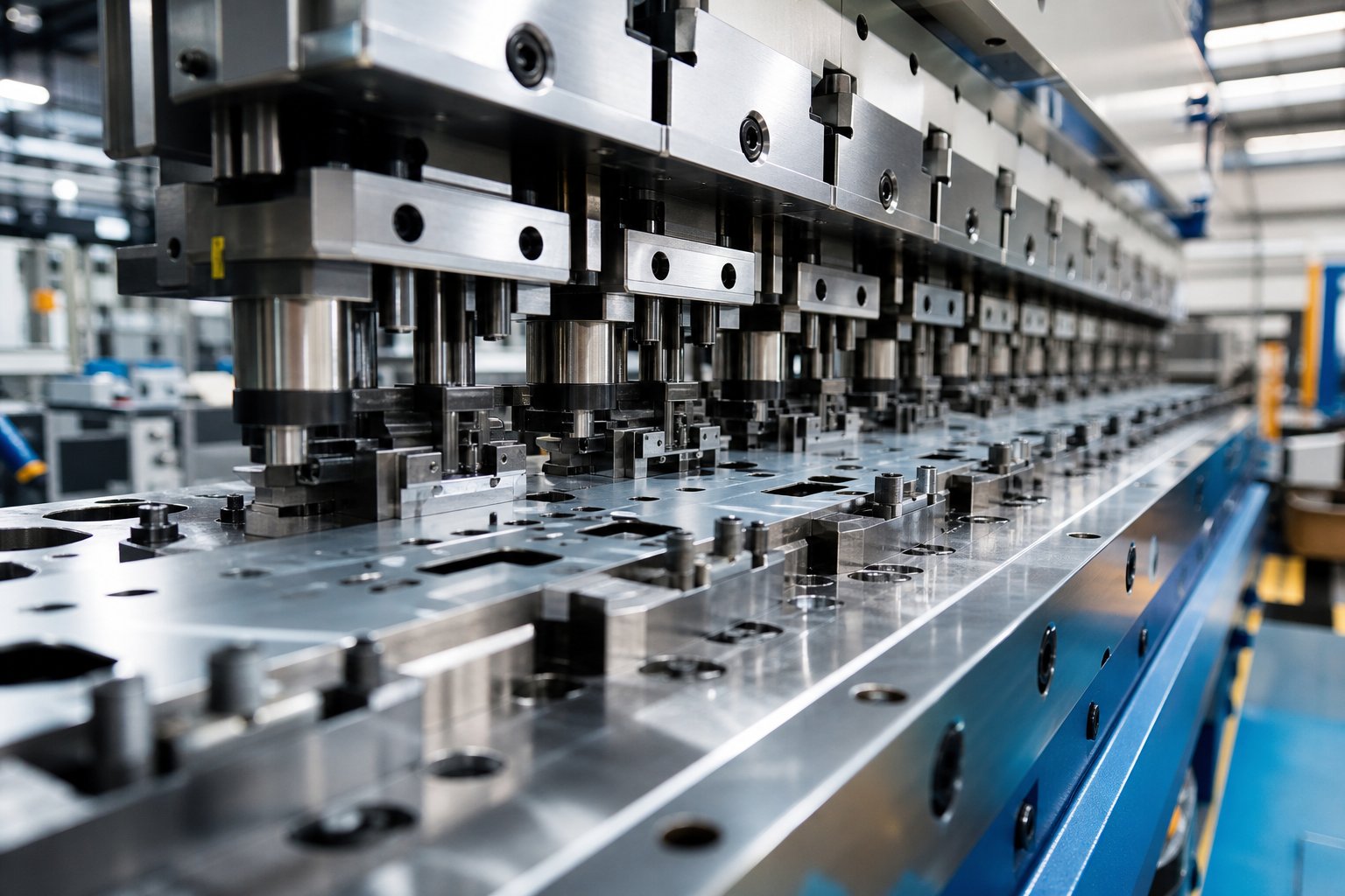
Progressive die stamping is a metal forming process in which a continuous strip of material advances through a series of sequential die stations within a single tool. Each station performs a discrete operation - blanking, piercing, forming, coining, or trimming - and with every press stroke, the strip indexes forward until a finished part is separated at the final station.
Imagine a coil of aerospace-grade alloy feeding into a press at speeds reaching hundreds of strokes per minute. At each station, the strip gains a new feature: a hole here, a bend there, a coined surface for sealing. The part never leaves the carrier strip until it is complete. That continuous-flow logic eliminates part handling between operations, removing a major source of dimensional variation and contamination risk.
For high volume aerospace precision stamping, this translates to thousands of identical components produced with tolerances often within ±0.001 inches - part after part, shift after shift.
Why Aerospace Demands Differ from Commercial Stamping
Commercial stamping prioritizes cost and speed. Aerospace stamping prioritizes those too, but layers on requirements that change the entire process architecture: full lot traceability, material certifications tied to specific mill heats, in-process inspection at defined intervals, and compliance with quality systems like AS9100.
Aerospace metal stamping repeatability is not just about holding a dimension. It is about proving you held that dimension on every single part, documenting the proof, and retaining it for decades. The progressive die stamping process definition stays the same across industries, but in aerospace, every station becomes a quality gate, and the die itself becomes a controlled document.
That distinction between commercial and aerospace stamping drives everything discussed in the sections ahead - from alloy selection and forming behavior to tooling validation and supplier qualification.
Aerospace Alloy Stampability and Material Selection
Every alloy tells the die what it can and cannot do. The progressive die stamping process depends on predictable material behavior at each station - predictable spring-back, predictable work-hardening, predictable fracture limits. Choose the wrong alloy or ignore how it responds under forming conditions, and you'll see cracking at bend stations, dimensional drift as the coil progresses, and accelerated tool wear that degrades part quality long before scheduled maintenance. Aerospace alloy progressive die formability is not a single number on a datasheet; it is a dynamic interaction between material properties, station sequencing, and press parameters.
Aluminum and Stainless Steel Behavior in Progressive Dies
Aluminum alloys are among the most common materials processed through aerospace progressive dies, but not all aluminum grades behave the same under sequential forming operations.
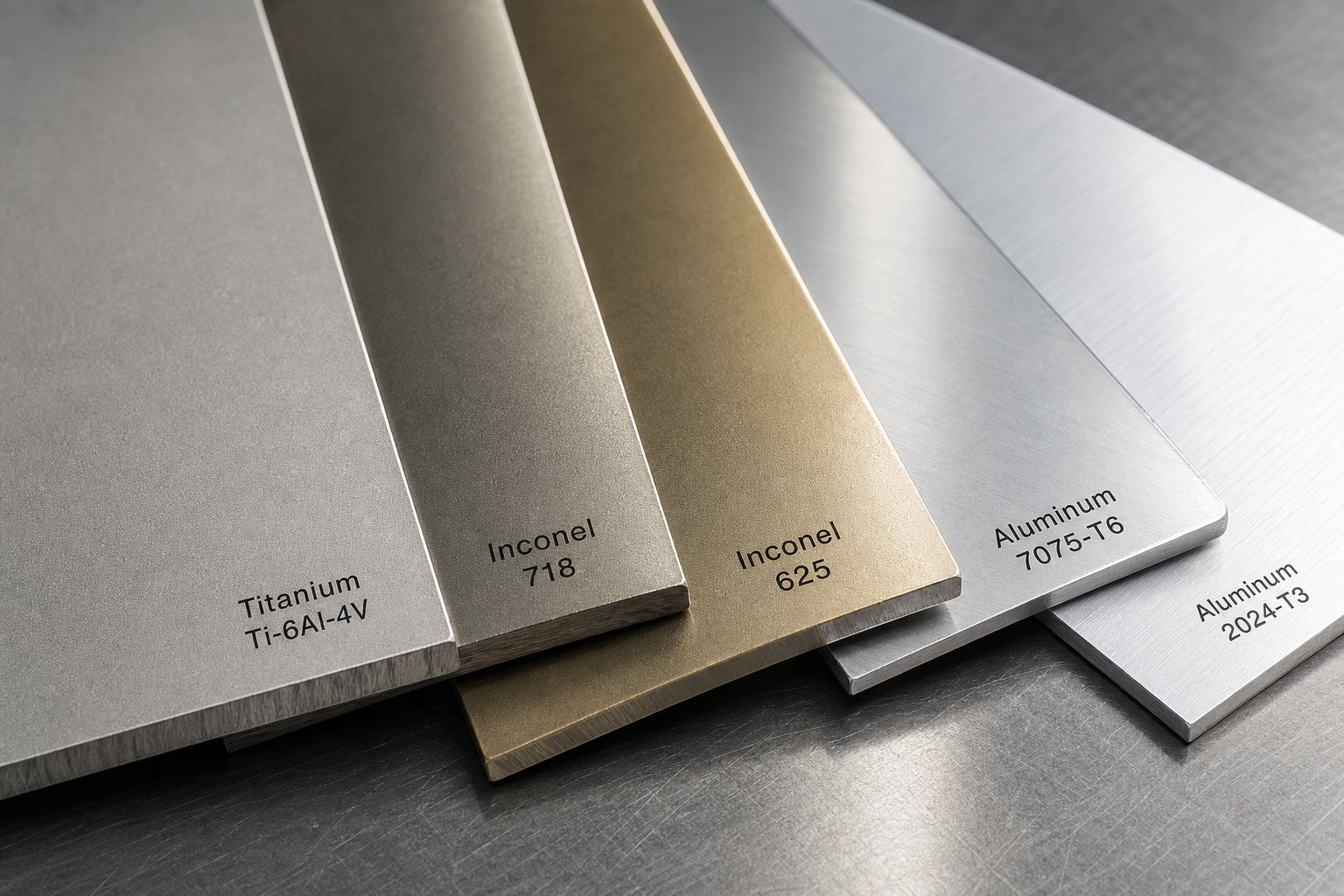
Alloy 2024-T3 offers good formability in its annealed condition and is widely used for structural brackets, clips, and shims. Its moderate work-hardening rate allows multiple forming stations without intermediate annealing. However, aluminum 7075 progressive die stamping presents a different challenge entirely. In T6 temper, 7075 is notoriously difficult to form at room temperature due to limited ductility. Research at Pacific Northwest National Laboratory has focused specifically on developing thermomechanical approaches to enable room-temperature stamping of 7075, because its high strength (over 600 MPa) makes it attractive for structural applications where it can replace heavier steel components. When progressive stamping 7075, engineers often specify W-temper (freshly solution-treated) material that provides a brief formability window before natural aging restores full hardness - meaning the stamping operation must be tightly time-controlled relative to heat treatment.
Stainless steels in the 300 series (particularly 304 and 316) offer excellent formability but work-harden rapidly. That rapid hardening means the force required at each progressive die station increases as the strip accumulates strain. Die designers must account for this escalating load when sequencing operations. Over-forming in early stations can leave insufficient ductility for later bends. Precipitation-hardened 17-4PH stainless steel adds another layer of complexity: it can be stamped in Condition A (solution-treated) for reasonable formability, but any subsequent aging treatment alters dimensions, so final tolerances must account for heat treatment distortion.
Stamping Superalloys and Titanium for Critical Applications
When components must survive extreme temperatures - turbine engine hardware, exhaust system elements, combustion liner brackets - the material conversation shifts to nickel-based superalloys and titanium grades. These alloys push progressive die tooling to its limits.
Stamping Inconel 718 in a progressive die demands high press tonnage, reduced forming speeds, and premium tool steels or carbide inserts at forming stations. Inconel 718 retains exceptional strength at temperatures up to 1,300 degrees F (704 degrees C), which makes it essential for jet engine and rocket components. That same high-temperature strength translates to extreme resistance to deformation at the press. Work-hardening in Inconel is aggressive - each forming station must be carefully calibrated to avoid exceeding the material's fracture limits. Inconel 625, with its superior fatigue and corrosion resistance, is similarly demanding but sees use in marine-aerospace crossover applications where both heat and salt exposure are factors.
Titanium progressive die stamping challenges are equally significant but stem from different root causes. Research published in Materials (Basel) documents that titanium alloys like Ti-6Al-4V present inferior formability and severe springback at room temperature due to a high strength-to-modulus ratio and hexagonal close-packed crystal structure. The forming limit of Ti-6Al-4V under conventional stamping rates is notably low - minimum major strains below 0.15 in some test conditions. For progressive die operations, this means fewer forming stations can apply aggressive bends, and over-bending compensation becomes critical at every station involving angular change.
Spring-Back Compensation and Work-Hardening Considerations
Spring-back compensation in aerospace stamping is not a single correction factor applied at the end of the process. Each alloy springs back differently, and each forming station must independently account for it. Titanium alloys exhibit the most severe springback among common aerospace materials - their high yield-strength-to-elastic-modulus ratio means a larger proportion of deformation is elastic and recovers after the punch retracts. Studies on Ti-6Al-4V show that spring-back can even be directionally anisotropic, varying with rolling direction in the source sheet.
For aluminum and stainless steel, spring-back is less extreme but still requires station-by-station overbend calculations. High-strength 7075 aluminum in aged tempers springs back more than softer 2024, and 17-4PH springs back more than annealed 304 - a direct function of yield strength relative to elastic modulus.
Work-hardening rates determine how much formability remains available at downstream stations. A material that hardens rapidly (like 304 stainless) may need its most aggressive forming operations front-loaded in the die sequence while the strip is still relatively soft. Conversely, a slowly hardening alloy like annealed 2024 aluminum gives designers more flexibility in station ordering. Improper sequencing for a high-hardening alloy leads to cracking at later stations - not because the individual bend is severe, but because cumulative strain has consumed the material's remaining ductility.
| Alloy | Typical Aerospace Application | Formability Rating | Spring-Back Tendency | Stamping Speed Considerations |
|---|---|---|---|---|
| Aluminum 2024-T3 | Structural brackets, clips, shims | Good (annealed: excellent) | Low to moderate | High-speed compatible; standard lubrication |
| Aluminum 7075-W/T6 | High-strength structural members | Poor in T6; moderate in W-temper | Moderate to high | Must stamp in W-temper window; time-critical |
| 304/316 Stainless Steel | Fluid system brackets, shielding | Good | Moderate | Moderate speed; rapid work-hardening limits multi-station forming |
| 17-4PH Stainless Steel | High-strength fastener hardware | Moderate (Condition A) | High | Reduced speed; account for post-stamp aging distortion |
| Ti-6Al-4V | Engine brackets, airframe clips | Poor at room temperature | Very high (anisotropic) | Slow press speed; aggressive lubrication; limited station count |
| Inconel 625 | Exhaust components, marine-aero hardware | Low | High | Slow speed; high tonnage; carbide tooling required |
| Inconel 718 | Turbine hardware, rocket engine parts | Low | High | Slow speed; extreme tool wear; frequent maintenance cycles |
One detail often overlooked: heat treatment requirements downstream directly influence how the progressive die sequence is planned. If a part will be solution-treated and aged after stamping (common for 17-4PH and certain titanium grades), dimensional changes from heat treatment must be anticipated in the die design. The stamped part is not the final part - it is the pre-heat-treatment geometry that, after thermal processing, arrives at the engineering drawing dimensions. Getting this relationship wrong means parts that measure perfectly off the press but fall out of tolerance after processing.
Material selection, then, is not simply a matter of picking an alloy that meets the service environment. It is an engineering decision that cascades through every aspect of die design - station count, forming force calculations, tool material selection, maintenance intervals, and downstream process planning. That cascade is exactly why process design and station sequencing deserve their own detailed examination.
Station-by-Station Process Breakdown for Aerospace Parts
Material behavior dictates what the die can attempt at each station - but station sequencing determines whether those attempts succeed consistently across a production run of ten thousand parts or ten million. In aerospace progressive die stamping, each station is not just a forming operation. It is a controlled process step with defined inputs, outputs, and verification criteria. The progressive die station sequence for aerospace components reflects this reality: quality is built into the die architecture, not inspected in after the fact.
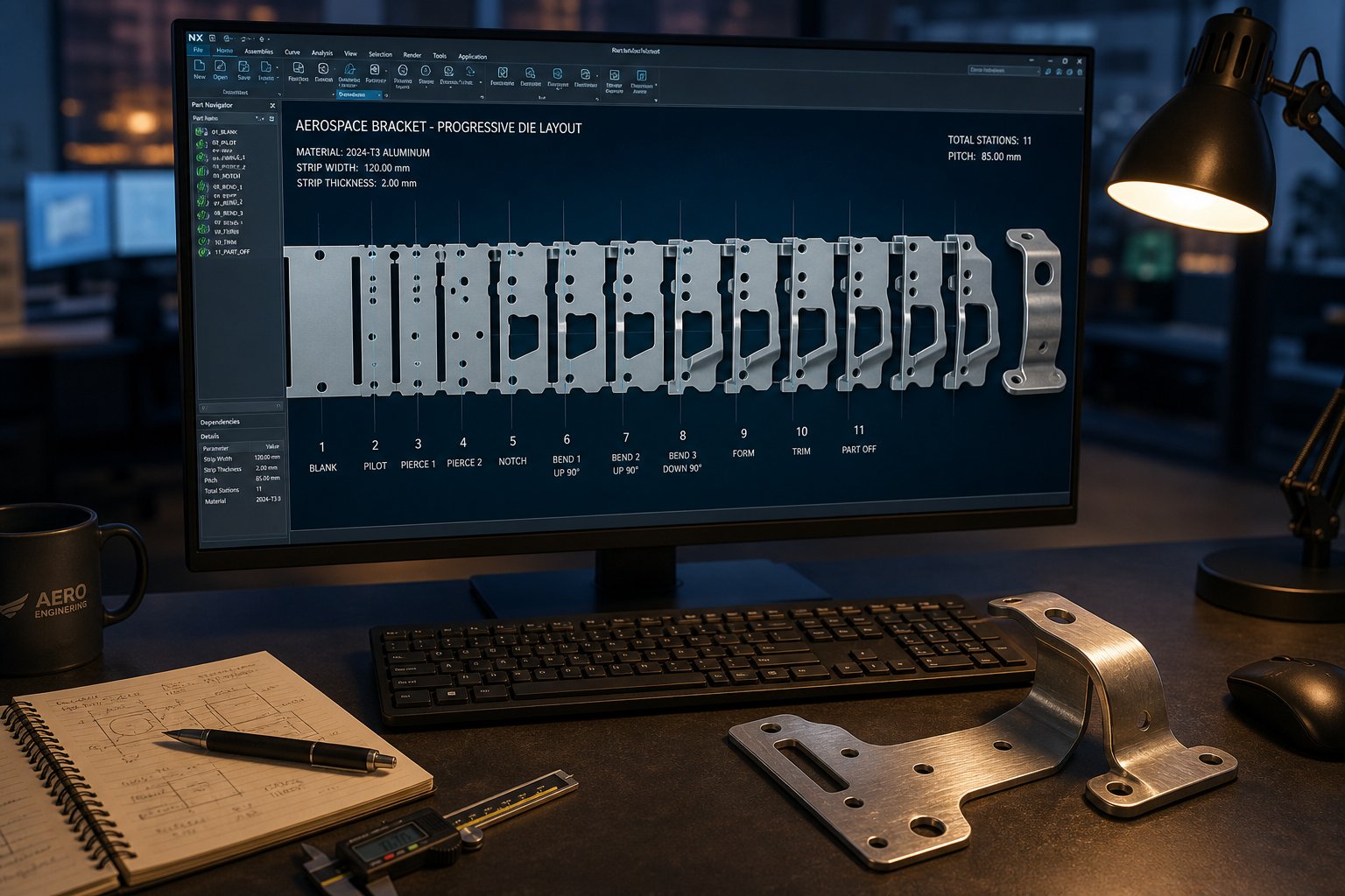
Here is a typical aerospace progressive die station sequence, with quality gates identified at each stage:
- Coil feed and pilot engagement - The strip advances by a fixed pitch and pilot pins engage pre-pierced holes to correct any feeder positional error. Aerospace quality gate: feed accuracy verification via servo encoder feedback, confirming pitch within ±0.0005 inches before the press stroke initiates.
- Pilot hole piercing - The first cutting station creates datum holes that all subsequent stations reference for alignment. These holes serve double duty as the traceability origin for dimensional inspection records.
- Blanking and profile piercing - Outer profiles, internal holes, slots, and relief features are cut. Aerospace quality gate: in-die sensors monitor punch penetration depth and detect abnormal force signatures that indicate worn or chipped cutting edges.
- Forming and bending - Three-dimensional features take shape through controlled angular displacement. Overbend compensation is built into each forming punch based on alloy-specific spring-back data.
- Coining and calibration - Critical surfaces and features are coined to final dimension, compressing material to eliminate residual spring-back and achieve tolerance bands below ±0.001 inches.
- In-die marking - Lot codes, serial identifiers, or date stamps are applied directly to the part surface while still in the strip, integrating traceability as a die station rather than a secondary process.
- Final trim and cutoff - The completed part is separated from the carrier strip. Aerospace quality gate: part ejection sensors confirm every part exits the die, preventing double-hits or slug packing.
Station count and sequencing decisions are driven by two primary factors: part geometry complexity and alloy formability constraints. A simple bracket in 2024 aluminum might need 8 stations. The same geometry in Inconel 718 could require 14 stations - additional idle stations for strip relaxation, extra forming stages with less aggressive per-station deformation, and dedicated calibration stations to fight severe spring-back.
Blanking and Piercing Stations for Aerospace Precision
Blanking and piercing seem straightforward - punch goes down, material separates. But achieving blanking piercing forming aerospace tolerances demands attention to details that commercial stamping can afford to ignore.
Punch-to-die clearance is the primary lever. For aerospace-grade stainless steels, typical starting clearance runs 15 to 25 percent of material thickness (total), with per-side values dialed tighter when burr height specifications are strict - common in aerospace where burrs can cause assembly interference or fatigue crack initiation. For aluminum alloys, clearance drops to 5 to 15 percent total, reflecting the material's lower shear strength and tendency toward larger rollover zones at excessive clearance.
Hole position accuracy in aerospace stamped parts typically needs to hold ±0.002 inches or better relative to datum features. This is achieved through the piloting strategy: pilot holes are pierced in the earliest stations, and every downstream station re-engages those pilots before performing work. Pilot-to-hole clearance for precision work typically falls around 0.0005 to 0.001 inches, tight enough to correct feeder error without deforming the pilot holes themselves.
Forming and Coining with Tight Tolerance Control
Forming stations are where the strip transitions from flat stock to a functional three-dimensional aerospace component. You'll notice that aerospace dies typically split forming operations into more stations than commercial equivalents - not because the geometry is more complex per se, but because each individual forming step is kept conservative to preserve material integrity and reduce cumulative strain.
A bend that commercial tooling might accomplish in a single station gets divided into a pre-bend and a final-form in aerospace applications, particularly when working with high-strength alloys. This staged approach reduces the risk of micro-cracking on the outer bend radius, which could become a fatigue initiation site in service.
Coining stations follow forming and serve as the precision guarantee. By compressing material under high localized pressure, coining eliminates the elastic spring-back that plagues formed features. Critical dimensions - mating surfaces, bearing areas, contact points - are coined to final size. This is especially important for titanium and high-strength stainless grades where spring-back compensation through overbending alone cannot reliably achieve the required ±0.001-inch tolerance band.
The sequencing logic is straightforward: create datum features first, perform major forming while the strip retains ductility, coin to final dimension, then cut off. Reversing this order - say, attempting to coin before all forming is complete - risks distorting previously calibrated features.
In-Die Inspection and Traceability Integration
Aerospace part traceability in a progressive die does not start at a marking station downstream. It is embedded in the die design from concept. Lot tracking, serial identification, and inspection access are planned alongside forming operations - they share real estate in the die and compete for station positions in the sequence.
In-die inspection for aerospace stamping relies on several sensor technologies working simultaneously. Proximity sensors detect the presence or absence of features on the strip - confirming that a punch has fully penetrated, a tab has been formed to the correct position, or a part has ejected properly. Micron sensors measure shut height with accuracy better than 0.00005 inches, detecting slug packing or material thickness variation that would otherwise go unnoticed until parts fall out of tolerance.
A practical caution: while sensors are valuable, too many sensors in a progressive die can lead to excessive false readings and production stoppages. The experienced approach is to use sensors creatively - one well-placed sensor can detect multiple failure modes rather than installing a separate sensor for every possible problem. In aerospace production, where unplanned downtime directly impacts delivery schedules tied to aircraft build rates, this balance between detection capability and production continuity is critical.
Traceability marking - whether laser-etched lot codes, embossed part numbers, or ink-jet date stamps - is performed while the part remains fixtured in the strip. This guarantees marking position consistency and eliminates handling damage that can occur when parts are marked in a separate operation. For aerospace programs requiring serialization of every individual part, in-die marking stations index a counter with each press stroke, assigning sequential identifiers without slowing production speed.
The combination of in-process sensing and integrated traceability transforms the progressive die from a forming tool into a self-documenting production system. Each part carries its identity from birth, and the process data captured during its creation links back to specific material lots, press parameters, and inspection results. That level of documentation does not just satisfy quality auditors - it provides the forensic trail needed when fleet-wide component reviews demand knowing exactly which parts were made under which conditions.
Still, even the most sophisticated station sequence means nothing if the part geometry was not designed to be manufacturable in the first place. Feature placement, bend radii, and strip layout efficiency all determine whether a progressive die can deliver aerospace-grade results - or whether it will fight the design at every station.
Design for Manufacturability in Aerospace Progressive Stamping
A part that looks perfect on a CAD screen can become a nightmare inside a progressive die if DFM progressive die stamping aerospace principles were ignored during design. The geometry you specify on an engineering drawing directly dictates station count, strip width, tool complexity, and ultimately whether the die can hold your tolerances at production speed without secondary operations. Getting DFM right upfront is not optional - engineering decisions in progressive die design dictate up to 80% of total production cost.
Bend Radii and Grain Direction Rules for Aerospace Alloys
The minimum bend radius aerospace alloy stamping can tolerate is a direct function of material type, temper condition, and grain orientation. The baseline rule - internal bend radii should be equal to or greater than material thickness (R ≥ T) - applies broadly, but aerospace alloys frequently demand more conservative ratios. Inconel 718 in solution-treated condition may require 2T minimum. Ti-6Al-4V at room temperature often needs 3T or greater to avoid outer-fiber cracking.
Grain direction stamping aerospace components is equally critical. Bends oriented perpendicular to the rolling direction reduce fracture risk because the material's elongated grain structure resists separation along that axis. When a part requires bends in multiple directions, the strip layout must position the most severe bend perpendicular to grain, even if that orientation reduces material utilization. For high-strength alloys like 7075-T6 or 17-4PH, ignoring grain orientation does not just increase reject rates - it creates latent crack initiation sites that may not be detectable until fatigue testing or, worse, in service.
Feature Proximity and Strip Layout Optimization
Feature proximity rules tighten significantly when you move from commercial metals to aerospace alloys. For commercial mild steel, holes can sit as close as one material thickness from an edge or bend. Aerospace alloys - particularly those with limited ductility or high work-hardening rates - need at least two times material thickness between any hole and an adjacent edge or formed feature to prevent distortion. Violating this spacing in titanium or Inconel does not produce a slightly out-of-spec part. It produces a cracked one.
Strip layout optimization for aerospace progressive die operations balances material yield against process reliability. Every part must nest within the strip width while leaving adequate carrier strip for piloting and progression. Wider carriers improve strip stability during forming of high-strength alloys but consume more material. The optimization target is not maximum material utilization - it is maximum yield of conforming parts. A layout that saves 5% on material but introduces feed instability and generates 2% scrap is a net loss once you factor in aerospace documentation costs for nonconforming material disposition.
Tolerances requested on engineering drawings must reflect what progressive die stamping can practically achieve. Flat dimensions and pierced features typically hold ±0.001 to ±0.002 inches. Formed features - bend angles, flange heights - realistically achieve ±0.003 to ±0.005 inches without secondary calibration. Specifying tighter tolerances on formed features forces additional coining stations, increasing die length, tooling cost, and maintenance burden. Sounds excessive? Consider that each added station also introduces one more potential source of positional error in the strip progression.
Designing for Inspection Access and Traceability Marking
Aerospace parts need measurable features - datum surfaces that a CMM probe can access, inspection points that optical comparators can read cleanly. If a critical dimension is buried inside a deep channel or hidden behind a flange, verifying it requires destructive sectioning or expensive CT scanning. Design features with inspection access in mind, and locate traceability markings on surfaces that remain visible after assembly without interfering with mating fits or sealing surfaces.
The following DFM pitfalls commonly increase tooling cost or compromise part quality in aerospace progressive stamping:
- Specifying bend radii below material thickness for high-strength alloys, forcing multiple forming stages or risking micro-cracks
- Placing holes or slots too close to bend lines, causing distortion during forming that pulls features out of position
- Ignoring grain direction in strip layout, leading to inconsistent spring-back and elevated fracture rates on tight bends
- Over-tolerancing formed features (calling out ±0.001 inches on bend angles) when the functional requirement only needs ±0.005 inches
- Designing part geometry that requires the strip to be excessively wide, wasting material and limiting press selection
- Failing to account for dimensional changes during downstream heat treatment, such as shrinkage or warpage that shifts features out of tolerance after processing
- Neglecting masking requirements for selective plating - if a feature cannot be easily masked, the plating process becomes a manual operation that adds cost and variability
- Locating traceability marks on surfaces that will be obscured after assembly or damaged during handling
Downstream processes deserve special attention during the stamping design phase. A part destined for solution treatment and aging (common with 17-4PH and titanium grades) will change dimensionally during thermal processing. DFM principles for heat treatment recommend accounting for these dimensional changes - including expansion, contraction, and stress-relief distortion - so that the as-stamped geometry transforms into the final drawing dimensions after processing, not before. Similarly, passivation and plating add material thickness to surfaces. If a stamped feature has a tight tolerance fit with a mating component, the plating buildup must be subtracted from the stamped dimension, not discovered as an interference problem during assembly.
These DFM decisions ripple forward into every production lot. A well-designed part runs at full press speed with predictable tool wear and minimal scrap. A poorly designed one demands constant intervention - adjusted press parameters, frequent tool sharpening, manual sorting of marginal parts. The difference is not subtle, and it shows up clearly when tolerance capabilities and quality control data are analyzed across sustained production runs.
Tolerance Capabilities and Quality Control for Aerospace Stamping
DFM decisions set the ceiling for what a progressive die can deliver. But understanding where that ceiling actually sits - and proving it stays there across every production lot - requires a clear picture of achievable aerospace progressive die stamping tolerances and the quality systems that verify them.
Achievable Tolerances by Part Category and Alloy
Not every stamped aerospace component demands the same precision. Tolerance expectations vary by part function, geometry type, and alloy behavior:
- Connector housings and terminals - Flat profile dimensions and pierced features: ±0.025 mm to ±0.05 mm. These parts typically involve thin copper alloys or stainless steels with good formability, enabling tighter control.
- Structural brackets and clips - Formed features like bend angles and flange heights: ±0.075 mm to ±0.125 mm. High-strength alloys and three-dimensional forming introduce more variation than flat cutting operations.
- EMI/RFI shielding components - Profile dimensions: ±0.05 mm. Formed enclosure features: ±0.10 mm. These parts prioritize consistent contact interfaces over absolute dimensional precision.
What drives tolerance variation in production? Three primary factors. First, tool wear - as cutting edges dull and forming surfaces degrade, dimensions drift. A sharp punch produces a clean hole at nominal; a worn punch produces an oversized hole with excessive burr. Second, material lot variation - even within the same alloy specification, hardness, thickness, and grain structure fluctuate between coils, changing spring-back behavior and forming response. Third, press speed - higher stroke rates increase dynamic forces and strip temperature, both of which affect dimensional outcomes. Running Inconel at 200 strokes per minute versus 80 produces measurably different results.
The table below frames progressive die stamping vs CNC machining tolerances and chemical etching for common aerospace geometries, giving engineers a realistic comparison for process selection:
| Feature Type | Progressive Die Stamping | CNC Machining | Chemical Etching |
|---|---|---|---|
| Hole position (relative to datum) | ±0.025 mm to ±0.05 mm | ±0.013 mm to ±0.025 mm | ±0.05 mm to ±0.075 mm |
| Flat profile dimensions | ±0.025 mm to ±0.05 mm | ±0.013 mm to ±0.025 mm | ±0.025 mm to ±0.05 mm |
| Bend angle | ±0.5 degrees to ±1 degree | N/A (no forming) | N/A (2D process) |
| Flange height (formed) | ±0.075 mm to ±0.125 mm | ±0.025 mm (machined from solid) | N/A (2D process) |
| Surface finish (Ra) | 0.8 to 1.6 micrometers | 0.4 to 1.6 micrometers | 0.8 to 3.2 micrometers |
| Production rate at tolerance | 200 to 600+ parts per minute | 1 to 10 parts per hour | Batch dependent (sheets) |
The takeaway: CNC machining achieves tighter absolute tolerances on individual features, but progressive stamping delivers remarkable consistency across millions of parts at speeds CNC cannot approach. For aerospace programs requiring 50,000 or more identical components, stamping's repeatability often matters more than the last few microns of absolute precision.
SPC Implementation and Process Capability Requirements
Holding tolerance is one thing. Proving you hold it - statistically, continuously, across every shift - is what SPC aerospace stamped parts production demands. Statistical process control in aerospace stamping is not optional documentation; it is the evidence that your process is stable and capable before parts ship.
Aerospace OEMs typically require demonstrated process capability indices of Cpk ≥ 1.33 for standard features and Cpk ≥ 1.67 for critical characteristics (safety-of-flight dimensions). These indices quantify how centered and tightly distributed your process output is relative to specification limits. A Cpk of 1.33 means the process uses no more than 75% of the available tolerance band - leaving margin for drift before nonconforming parts appear.
Practical SPC implementation for progressive die stamping involves:
- Defining key characteristics (KCs) on each part - the 3 to 8 dimensions that most affect fit, function, or safety
- Sampling at defined intervals (typically every 500 to 2,000 strokes, or at each coil change)
- Plotting X-bar and R charts for each KC, with control limits calculated from initial capability studies
- Establishing reaction plans triggered by out-of-control signals - not just out-of-specification conditions, but trends and shifts that predict future nonconformance
The real value of SPC in progressive stamping is its ability to detect tool wear trends before they produce scrap. A gradual upward drift in hole diameter, tracked over consecutive sample groups, signals punch wear that can be corrected during scheduled maintenance rather than discovered during final inspection after thousands of parts have already been stamped.
First Article Inspection and Ongoing Production Verification
Before any production lot ships, AS9102 first article inspection stamping protocols verify that the entire production system - tooling, material, press setup, operator procedures - produces conforming parts. AS9102C standardizes FAI process requirements across all levels of the aerospace supply chain, providing consistent documentation for production process verification.
An FAI under AS9102 is not simply measuring a few critical dimensions. Every single dimension on the engineering drawing must be measured on the physical part and documented in a First Article Inspection Report (FAIR). For a complex stamped bracket with 40 dimensioned features, that means 40 individual measurements compared against print specifications - plus material verification, process documentation review, and functional test results where applicable.
When does FAI apply? Beyond the obvious first production run, AS9102 requires re-verification after any design change, manufacturing process change, material source change, or production lapse exceeding two years. For progressive die operations, this means a new FAI is triggered by die refurbishment that alters forming geometry, a change in strip material supplier, or resumption of a program that has been dormant.
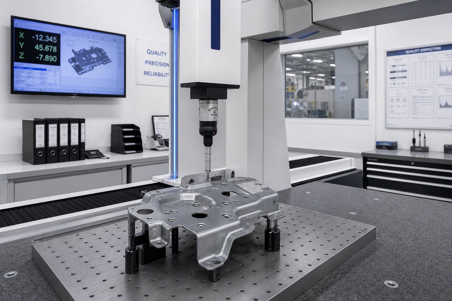
CMM verification of stamped aerospace components provides the dimensional backbone of both FAI and ongoing production inspection. Coordinate measuring machines capture three-dimensional feature positions, profile tolerances, and angular relationships that hand tools cannot reliably measure on formed sheet metal parts. For production verification beyond FAI, CMM sampling at defined intervals (per lot, per shift, or per coil change) generates the measurement data that feeds SPC charts and confirms ongoing process stability.
Additional verification methods for stamped aerospace components include:
- Visual inspection per defined criteria - checking for burrs exceeding maximum allowable height, surface scratches within cosmetic zones, and forming cracks visible under magnification
- Surface finish measurement - profilometer readings on critical sealing or contact surfaces, verifying Ra values remain within specification as tools wear
- Optical comparator inspection - overlaying part profiles against tolerance-banded master drawings for quick verification of complex contours
- Go/no-go functional gauging - custom fixtures that verify critical interface dimensions (pin fit, slot engagement, mating surface flatness) at production speed without requiring CMM time
Together, these quality systems create a verification architecture where tolerance capability is not just claimed - it is demonstrated at first article, monitored throughout production, and documented with enough rigor to satisfy auditors, OEM quality engineers, and airworthiness authorities alike. That documentation burden, along with the certifications and regulatory frameworks behind it, is what fundamentally separates aerospace stamping operations from their commercial counterparts.
Aerospace Certifications and Regulatory Compliance in Stamping
The quality systems described in the previous section - SPC, FAI, CMM verification - do not exist in a vacuum. They operate within a regulatory framework that dictates how an aerospace stamping operation documents, controls, and proves everything it does. This framework is what separates an AS9100 certified progressive die stamping facility from a commercial shop that happens to own similar press equipment.
AS9100 and NADCAP Requirements for Stamping Operations
AS9100 Rev D builds on ISO 9001 but adds aerospace-specific requirements that fundamentally change how a stamping operation manages quality. Where ISO 9001 allows flexibility in documentation depth, AS9100 demands complete traceability from raw material receipt through final delivery, with documented procedures for every process step, non-conformance disposition, and corrective action. Risk management receives heavy emphasis - you need systems to identify potential failures before they produce nonconforming parts, assess the impact of any process change, and monitor supplier performance continuously.
For a progressive die stamping operation specifically, AS9100 compliance means every die is a controlled document with revision history. Every press setup parameter is recorded. Every material coil is linked to a specific mill heat lot. Staff training records must demonstrate competency in quality control processes, material handling, and testing methods - and those records need regular refresher verification. Most companies need 12 to 18 months of preparation before achieving initial certification, and maintaining it requires ongoing internal audits and surveillance assessments.
NADCAP accreditation for metal stamping in aerospace enters the picture when special processes are performed in-house. Stamping itself is not typically a NADCAP-accredited process, but heat treating and surface finishing performed by the same facility require separate NADCAP accreditation. If your stamped 17-4PH brackets go directly from the press to an in-house aging furnace, that heat treatment operation must meet NADCAP audit standards - calibrated equipment, qualified procedures, and process controls validated through industry-standard test coupons. Outsourcing these processes to a NADCAP-accredited vendor is an alternative, but it adds lead time and handling steps.
ITAR Compliance and Defense Program Documentation
Defense-related progressive die stamped components introduce another regulatory layer entirely. ITAR compliance for an aerospace stamping supplier means facility security controls, restricted access to technical data, and limitations on who can view engineering drawings or process documentation. Foreign national employees may be restricted from defense program work areas. Digital files - CAD models, die designs, inspection data - must reside on secured networks with access logging.
The practical impact? An ITAR-compliant stamping facility operates with physical segregation of defense and commercial work, background-checked personnel, and cybersecurity infrastructure that a commercial-only shop does not maintain. These requirements flow down to subcontractors as well - your material supplier, your heat treat vendor, and your plating house all need appropriate compliance status if they handle ITAR-controlled articles or data.
Material Certifications and Lot Traceability Standards
Every coil of aerospace alloy entering a progressive die must arrive with documentation that proves exactly what it is. Mill test reports (MTRs) provide chemical composition analysis, mechanical property test results, and the heat lot number that becomes the traceability anchor for every part stamped from that coil. AS9100 Clause 8.5.2 requires unique identifiers and documented traceability linking each component from raw material receipt through final delivery, with records that must remain accessible for 20 to 40 years depending on the component's service life.
Aerospace stamping lot traceability requirements mean that if a quality issue surfaces on an aircraft five years from now, you can trace backward from the installed part to the exact production lot, the exact coil, the exact mill heat, and the exact press conditions under which it was made. That chain cannot have gaps. Certificates of conformity per AS9163 must include part identification, conformity statements, supporting evidence references, and authorized personnel traceability - not just a signature on a shipping document.
A qualified aerospace stamping supplier should provide the following minimum documentation package with each production lot:
- Certificate of Conformity (CoC) per AS9163 with lot/batch identification and explicit conformity statement
- Mill test reports for all raw materials, traceable to specific heat lot numbers
- First Article Inspection Report (per AS9102) for initial production or after any process change
- In-process inspection records and SPC data demonstrating process stability
- Final dimensional inspection results referencing engineering drawing revision
- Material traceability records linking finished part lot to raw material heat number
- Non-destructive test results where specified (visual inspection reports, surface finish measurements)
- Heat treatment or surface finish certifications from NADCAP-accredited sources where applicable
- Non-conformance reports and disposition records for any deviations encountered during the lot
How do these requirements affect production reality? Significantly. Compared to non-aerospace stamping, you're looking at 15 to 25 percent longer lead times driven by documentation preparation, inspection hold points, and supplier certification verification. Cost structures reflect the overhead of maintaining quality systems, retaining records for decades, training staff to aerospace standards, and undergoing regular third-party audits. Budget items include documentation systems, testing equipment, calibration services, external consultants, and audit fees - none of which exist in a commercial-only stamping operation.
The return on that investment is access to programs where compliance is non-negotiable and where the cost of failure - a grounded fleet, an airworthiness directive, a recall - dwarfs the cost of doing the paperwork right. These certifications and documentation standards also serve as a filtering mechanism, narrowing the field of qualified suppliers and making process selection decisions more consequential. Choosing the right manufacturing method is not just a technical question - it is a question of which process can deliver parts within this regulatory architecture at a cost and volume that make economic sense.
When to Choose Progressive Die Stamping Over Alternative Methods
Certifications and documentation separate qualified suppliers from unqualified ones - but the more fundamental question is whether progressive die stamping is even the right process for your specific component. Every aerospace program has a different combination of volume, geometry, tolerance, and material that tips the scale toward or away from progressive tooling. This aerospace stamping process selection guide frames that decision clearly.
Volume and Complexity Thresholds for Progressive Die Viability
The progressive die stamping volume threshold cost equation is straightforward: high tooling investment divided across many parts equals low unit cost. But where exactly does that crossover happen?
For aerospace components, economic viability typically starts at 50,000 to 100,000 units per year, though ultra-simple geometries in easy-to-form alloys can sometimes justify tooling at 30,000 units. Below those volumes, the tooling cost - ranging from $30,000 to over $250,000 depending on station count and alloy - dominates per-part economics. A $100,000 die spread across 10,000 parts adds $10 per unit in tooling alone. Spread across 500,000 parts, it drops to $0.20.
Part geometry determines whether progressive stamping can even physically produce the component. The process excels at small-to-medium parts that can be reduced to a flat strip pattern - brackets, clips, terminals, shielding enclosures, spring contacts. Features must remain achievable through sequential blanking, piercing, and forming operations while the part stays attached to a carrier strip. Depth-to-width ratios exceeding roughly 1:1 push beyond what carrier-strip-based progression can handle without tearing.
Comparative Cost Analysis Against Alternative Processes
When evaluating progressive die stamping vs hydroforming for aerospace applications, the distinction comes down to geometry and volume. Hydroforming produces complex, deep-drawn shapes with uniform wall thickness - ideal for structural panels or ducts that need smooth curves impossible to achieve through sequential bending. But hydroforming cycle times are slower, and unit costs at high volume cannot compete with progressive stamping's speed of 200 to 600+ strokes per minute.
The transfer die vs progressive die aerospace parts decision hinges on part size and draw depth. Transfer stamping separates the part from the strip early and moves it mechanically between stations. This suits larger components or deep-drawn geometries that would tear a carrier strip. The tradeoff: transfer stamping is slower than progressive due to mechanical reset time between stations, and handling introduces additional dimensional variation.
CNC machining achieves the tightest tolerances of any alternative but produces parts one at a time. For a bracket that needs 50,000 units per year, machining each from solid billet is economically unviable. Chemical etching handles extremely thin materials and complex 2D patterns well but cannot create three-dimensional formed features.
| Process | Ideal Volume Range (Annual) | Typical Tolerance | Relative Unit Cost at Volume | Tooling Investment |
|---|---|---|---|---|
| Progressive Die Stamping | 50,000 to 1,000,000+ | ±0.025 mm to ±0.125 mm | Lowest | $30,000 to $250,000+ |
| Transfer Die Stamping | 25,000 to 500,000 | ±0.05 mm to ±0.15 mm | Low | $40,000 to $200,000+ |
| CNC Machining | 1 to 5,000 | ±0.013 mm to ±0.025 mm | Highest | Minimal (fixtures only) |
| Hydroforming | 5,000 to 50,000 | ±0.05 mm to ±0.25 mm | Medium-High | $20,000 to $100,000 |
| Chemical Etching | 1,000 to 100,000 | ±0.025 mm to ±0.075 mm (2D only) | Medium | $500 to $5,000 (photo tools) |
Cross-Industry Progressive Stamping Versus Aerospace-Specific Demands
Progressive die stamping serves automotive, electronics, and medical device production with the same fundamental mechanics. But aerospace adaptations change the cost equation. Automotive stamping prioritizes raw speed and minimal die maintenance. Aerospace stamping adds in-die inspection stations, traceability marking, conservative forming sequences for exotic alloys, and documentation overhead that extend cycle planning and increase per-part cost - even at identical volumes.
An automotive connector stamped at 400 strokes per minute in phosphor bronze might cost $0.03 per unit. The same geometry in 17-4PH stainless for an aerospace flight control system - stamped at 150 strokes per minute with SPC sampling, lot traceability, FAI documentation, and NADCAP-certified heat treatment - might cost $0.25 per unit. Same process, vastly different operational context.
When is progressive die stamping NOT the right choice? Be honest with yourself about these scenarios:
- Annual volumes below 10,000 to 20,000 units - tooling amortization crushes unit economics; laser cutting plus press brake forming delivers better total cost
- Material thickness exceeding 4 to 6 mm - press tonnage requirements escalate, strip progression becomes mechanically difficult, and transfer or single-station stamping is more practical
- Deep draws exceeding a 1:1 depth-to-diameter ratio - the carrier strip cannot sustain the material draw without tearing; transfer stamping or hydroforming handles this better
- Parts requiring frequent design changes - a late-stage design change can cost half the original tool price; if the design is not frozen, do not commit to progressive tooling
- Extremely tight tolerances on all features (below ±0.013 mm) - CNC machining from solid is more appropriate for parts where every dimension demands single-digit-micron precision
The decision framework is ultimately about matching process economics to program realities. High volume, frozen design, moderate complexity, and thin-to-medium sheet material in aerospace alloys - that is the sweet spot. Outside that window, forcing progressive die stamping onto an application increases cost, extends lead time, and may not even produce superior parts. Knowing where the boundaries sit protects both budget and schedule - and sets realistic expectations for the tooling development and validation lifecycle that follows the process selection decision.
Tooling Design, Validation, and Production Lifecycle Management
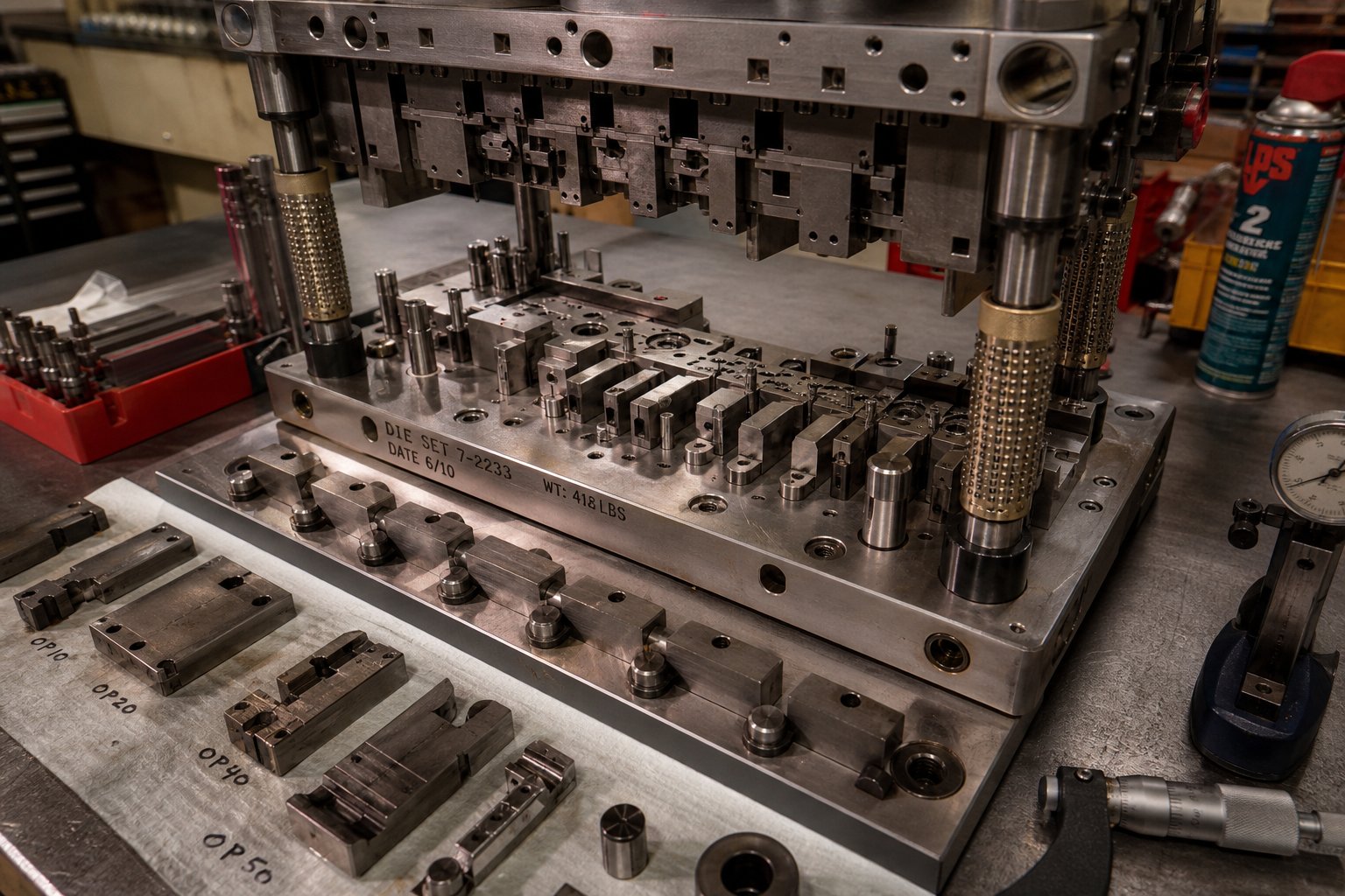
Selecting progressive die stamping as your manufacturing process is only the starting point. The real engineering challenge lives in the aerospace progressive die tooling lifecycle - designing, validating, qualifying, and maintaining a die that produces conforming parts not just during first article but across multi-year production campaigns spanning hundreds of thousands of strokes.
Simulation and Prototyping for Aerospace Die Development
Imagine committing $150,000 to a hardened production die only to discover at tryout that station six cracks the material or station nine produces unacceptable spring-back. FEA simulation for progressive die design in aerospace eliminates that risk by virtualizing the entire forming sequence before any steel is cut.
Modern incremental forming simulation software - tools like AutoForm's ProgSim, Altair Inspire Form, and PAM-STAMP - acts as a virtual tryout press. These platforms model material flow through each station, predicting formability issues such as splits, wrinkles, and excessive thinning while simultaneously calculating spring-back at every forming stage. The result: engineers can optimize station sequencing, adjust overbend angles, and verify blank development before committing to physical tooling.
For aerospace alloys specifically, simulation catches problems that experience alone cannot predict. Work-hardening accumulation across multiple stations, anisotropic spring-back in titanium, and localized thinning in Inconel bends all become visible in the virtual model. A single simulation iteration might take minutes for simple geometries or several hours for complex multi-station superalloy dies - but that time investment prevents weeks of physical tryout rework.
The prototyping progression typically follows three stages: soft tooling (aluminum or mild steel dies for geometry validation), semi-hardened prototype dies (for material behavior verification at reduced production speed), and finally hardened production tooling in D2, M2, or carbide-inserted configurations designed for the full production run.
Tool Life Management and Maintenance Scheduling
A progressive die maintenance schedule for aerospace production cannot rely on reactive response - waiting until parts drift out of tolerance before servicing the tool. Best-in-class maintenance practice requires identifying, measuring, and assessing every area of the tool that will degrade over time, then documenting exactly how each degradation item is serviced.
Aerospace dies typically operate on defined stroke-count service intervals - commonly every 50,000 to 150,000 strokes depending on material hardness and station complexity. Each service includes:
- Inspection and sharpening of all cutting sections (punches and die buttons), with documented grind amounts to track cumulative stock removal
- Measurement and replacement of pilots that show wear beyond allowable diameter reduction
- Verification of forming insert dimensions against original tool prints, replacing any component showing measurable drift
- Spring and lifter assessment for fatigue or set, with replacement at defined cycle thresholds rather than failure
- Timing verification on all cam-driven or delayed-action inserts
The critical insight from experienced toolrooms: consistency in maintenance execution matters as much as frequency. If every technician sharpens a punch by a different amount or polishes forming inserts with different media, the die produces different results after each service - defeating the predictability that aerospace production demands. Documented procedures with specific tolerances eliminate this variability.
How Tooling Expertise Affects Part Consistency Over Long Runs
Punch and die wear follows predictable patterns that experienced toolmakers use to forecast maintenance needs. Cutting edges develop radius wear that gradually increases burr height on pierced features. Forming surfaces develop polishing wear that changes friction conditions and subtly alters bend angles. These patterns are measurable through SPC data - a gradual dimensional shift on control charts signals the approach of a service interval long before parts reach specification limits.
The refurbishment-versus-replacement decision depends on cumulative condition. A punch that has been sharpened ten times has lost significant length, changing its penetration depth and potentially its alignment with the die button. At some point - typically when cumulative stock removal exceeds 10 to 15 percent of original working length - replacement becomes necessary regardless of current edge condition.
For superalloy progressive die tooling validation, the stakes are higher. Dies processing Inconel 718 or similar high-temperature alloys experience accelerated wear due to the extreme forming forces involved. Carbide inserts and specialized coatings (TiAlN, AlCrN) extend service intervals but also increase replacement cost, making accurate wear tracking essential for cost management. YICHEN's aerospace superalloy progressive die provides a practical example of tooling specifically engineered for dimensional control in high-temperature alloys - addressing the superalloy stamping challenges discussed earlier through material-specific tooling design that manages these aggressive wear patterns while maintaining stable production output.
Hexagon's Die Life Analysis module for Simufact Forming represents the direction the industry is heading: fully integrated tool-life prediction that identifies failure locations and estimates expected component longevity before production begins. This allows maintenance planning to shift from reactive schedules to predictive models based on actual stress and strain distributions within the tooling.
The goal across the entire tooling lifecycle is a predictable process - one where you can forecast service intervals, plan spare component inventory, and guarantee dimensional consistency from the first part off a freshly serviced die to the last part before the next service window. That predictability is what buyers should evaluate when qualifying a stamping supplier, and it is visible in how a supplier communicates their tooling capabilities, maintenance documentation, and process transparency.
Sourcing and Supplier Qualification for Aerospace Stamped Parts
Tooling predictability and maintenance discipline only deliver value if the supplier behind them can actually be trusted with your program. The transition from process selection to procurement is where many aerospace engineers discover that not every stamping shop advertising "aerospace capability" can back that claim under audit. Sourcing progressive die stamped aerospace parts demands a structured approach - from how you write specifications through how you evaluate potential partners and plan realistic timelines.
Writing Effective Specifications for Stamped Aerospace Parts
A poorly written specification creates ambiguity, and ambiguity in aerospace manufacturing creates nonconforming parts. When you draft a stamping specification for progressive die components, you're communicating not just geometry but intent - what matters functionally, what requires traceability, and where the supplier has flexibility.
Effective specifications for aerospace stamped parts include:
- Clear identification of key characteristics (KCs) - flag the 3 to 8 dimensions that affect fit, function, or safety, distinguishing them from non-critical features where standard tolerances apply
- Material callouts referencing specific specifications - cite AMS or ASTM numbers rather than generic alloy names (e.g., AMS 5643 for 17-4PH, not just "17-4 stainless")
- Surface finish requirements by zone - define Ra limits on functional surfaces while allowing manufacturing finish on non-critical areas
- Post-stamping process requirements - specify heat treatment conditions, passivation per ASTM A967 or AMS 2700, plating thickness and type, with masking callouts where selective coverage is needed
- Inspection and acceptance criteria - reference AS9102 for FAI, define SPC requirements for production, and specify sampling plans for ongoing verification
- Traceability and marking requirements - state lot-level versus serial-level marking, marking method (laser etch, ink stamp, emboss), and location on the part
One common mistake: over-tolerancing every feature to the same tight band. This signals to suppliers that the engineer does not understand which dimensions actually matter - and it inflates quotes because the tooling must be built to hold unnecessarily tight control everywhere. Specify tight tolerances only where function demands them. Let standard progressive die capability (typically ±0.05 mm on flat features) apply everywhere else.
Supplier Qualification Criteria and Audit Considerations
An aerospace stamping supplier qualification audit is not a checkbox exercise. Supplier-related defects account for 30 to 50 percent of quality issues in aerospace, which means your audit needs to verify real capability - not just certifications hanging on a wall.
When evaluating supplier evaluation criteria for aerospace metal stamping, look for evidence across these categories:
- Demonstrated superalloy and aerospace alloy tooling expertise - suppliers should show progressive die tooling designed for demanding materials, with documentation of dimensional control methods and maintenance protocols. YICHEN's aerospace superalloy progressive die page exemplifies what to look for: transparent presentation of material specialization, equipment capabilities, and process documentation that gives buyers confidence in tooling-focused competence for high-temperature alloys.
- Active AS9100 certification with evidence of system use - beyond holding certification, engineers should look for documented process controls, corrective and preventive action systems, internal audits tied to continuous improvement, and management involvement in quality performance
- In-house tooling design and fabrication - suppliers who design, build, and maintain their own progressive dies control the full quality loop; outsourced tooling adds handoffs and communication gaps
- Statistical process control infrastructure - SPC software, defined sampling protocols, demonstrated Cpk data from current production runs, and clear reaction plans when signals trigger
- Material traceability systems - the ability to link any finished part back through its production lot, coil, and mill heat with documentation retained for decades
- ITAR registration and compliance infrastructure - if defense programs are involved, verify facility security, personnel screening, and data handling controls
- Engineering collaboration capability - aerospace engineers value suppliers who engage early and offer manufacturability insight, including feedback on tolerances, material selection, and tooling strategy
Red flags during an audit that indicate an under-qualified supplier:
- No dedicated aerospace quality personnel - aerospace work managed by the same team running commercial jobs with no differentiation
- Inability to produce SPC data from current production runs, or charts that show no reaction to out-of-control signals
- Tool maintenance performed reactively (after parts fail inspection) rather than on defined stroke-count schedules
- Material certifications filed loosely without clear linkage between coil lot numbers and finished part lots
- Reluctance to share process capability studies or historical FAI data
- No forming simulation capability - relying entirely on trial-and-error during die tryout
A risk-based qualification approach - classifying suppliers by criticality and applying tailored evaluation methods - ensures you invest audit resources where they matter most. High-risk suppliers producing flight-critical stamped components warrant on-site audits, first article verification, and process capability studies. Lower-risk commodity suppliers may qualify through documentation review and sample evaluation.
Lead Time Planning from Tooling Through Production Delivery
Aerospace stamping lead time for tooling development consistently surprises buyers who compare it to commercial stamping timelines. A production-quality progressive die typically requires 12 to 20 weeks to design, machine, heat treat, grind, assemble, and commission. Complex dies for superalloy components or tight-tolerance applications can push beyond 20 weeks when forming simulation iterations and prototype validation stages are included.
A realistic timeline from program award to production delivery looks like this:
| Phase | Typical Duration | Key Activities |
|---|---|---|
| Design and simulation | 4 to 6 weeks | Strip layout, FEA forming simulation, station sequencing, design review |
| Tool fabrication | 8 to 14 weeks | CNC machining, wire EDM, heat treatment, grinding, assembly |
| Tryout and validation | 2 to 4 weeks | Initial sampling, dimensional verification, forming adjustments |
| First Article Inspection | 1 to 2 weeks | Full AS9102 FAIR documentation, customer approval |
| Production ramp | 2 to 4 weeks | Process capability study, SPC baseline establishment |
| Total tooling through first production | 17 to 30 weeks |
After qualification, ongoing production lead times drop dramatically - repeat orders for established parts typically ship in 4 to 8 weeks depending on material availability and order volume. But that initial tooling investment in time is non-negotiable. Attempting to compress it by skipping simulation, rushing tryout, or shortcutting FAI documentation creates quality debt that surfaces as production problems, customer rejections, or - worst case - field failures.
One final consideration: a late-stage design change after the die is mostly complete can cost as much as half the original tool price. Lock your design before authorizing tooling fabrication. If design maturity is uncertain, invest in prototype validation through soft tooling or CNC-fabricated samples before committing capital to hardened production dies. The cost of a $5,000 prototype run is trivial compared to a $75,000 die rework triggered by a post-fabrication engineering change.
Sourcing aerospace stamped components is ultimately a risk management exercise. The supplier you choose inherits responsibility for flight-critical hardware - their process discipline, tooling expertise, and documentation rigor become extensions of your own quality system. Evaluate accordingly, plan timelines realistically, and write specifications that leave no room for misinterpretation. The parts that emerge from that partnership will reflect the clarity and rigor you invested at the front end.
FAQs About Progressive Die Stamped Parts for Aerospace Industry
1. What tolerances can progressive die stamping achieve for aerospace components?
Progressive die stamping typically achieves ±0.025 mm to ±0.05 mm on flat profile dimensions and pierced features for aerospace parts. Formed features like bend angles hold ±0.5 to ±1 degree, while flange heights reach ±0.075 mm to ±0.125 mm. These tolerances depend on alloy type, tool condition, and press speed. Coining stations can push critical features below ±0.025 mm. While CNC machining delivers tighter absolute precision on individual parts, progressive stamping maintains remarkable consistency across production runs of hundreds of thousands of units, making it the preferred choice when repeatability at volume matters more than ultimate single-part accuracy.
2. What certifications should an aerospace progressive die stamping supplier hold?
A qualified aerospace stamping supplier should hold AS9100 Rev D certification as a baseline, demonstrating a quality management system with full traceability from raw material through delivery. NADCAP accreditation is required if the supplier performs special processes in-house such as heat treatment or surface finishing. For defense-related components, ITAR registration with verified facility security and data handling controls is mandatory. Beyond certifications, buyers should verify active SPC implementation, AS9102-compliant first article inspection capability, documented tool maintenance programs, and material traceability systems linking finished parts to specific mill heat lots with records retained for decades.
3. What is the minimum production volume that justifies progressive die stamping for aerospace parts?
Economic viability for aerospace progressive die stamping typically starts at 50,000 to 100,000 units annually, though simple geometries in easily formed alloys can justify tooling at 30,000 units. The calculation is straightforward: tooling investment ranges from $30,000 to over $250,000 depending on complexity and alloy. A $100,000 die spread across 10,000 parts adds $10 per unit in tooling cost alone, but across 500,000 parts it drops to $0.20. Below the threshold, alternatives like laser cutting with press brake forming or CNC machining deliver better total cost of ownership.
4. Which aerospace alloys can be processed through progressive die stamping?
Common aerospace alloys processed via progressive die stamping include aluminum 2024-T3 and 7075 (in W-temper for formability), 300-series stainless steels (304, 316), precipitation-hardened 17-4PH stainless, titanium Ti-6Al-4V, and nickel superalloys like Inconel 625 and 718. Each alloy presents unique challenges. Aluminum 7075 requires stamping within a narrow W-temper window before aging. Titanium exhibits severe anisotropic springback and limited room-temperature formability. Inconel demands high press tonnage, slow speeds, and carbide tooling due to aggressive work-hardening. Material selection cascades through die design affecting station count, forming forces, maintenance intervals, and downstream heat treatment planning.
5. How long does it take to develop progressive die tooling for aerospace production?
The complete timeline from program award to first production delivery typically spans 17 to 30 weeks. This breaks down into design and simulation (4 to 6 weeks), tool fabrication including CNC machining, wire EDM, and heat treatment (8 to 14 weeks), tryout and validation (2 to 4 weeks), AS9102 first article inspection (1 to 2 weeks), and production ramp with SPC baseline establishment (2 to 4 weeks). Complex superalloy dies may exceed 20 weeks for fabrication alone. After qualification, repeat production orders typically ship in 4 to 8 weeks. Late-stage design changes after tooling fabrication begins can cost up to half the original tool price, so design freeze before authorization is critical.


