


What Are Dies for Stamping Metal
Definition and Core Function of a Stamping Die
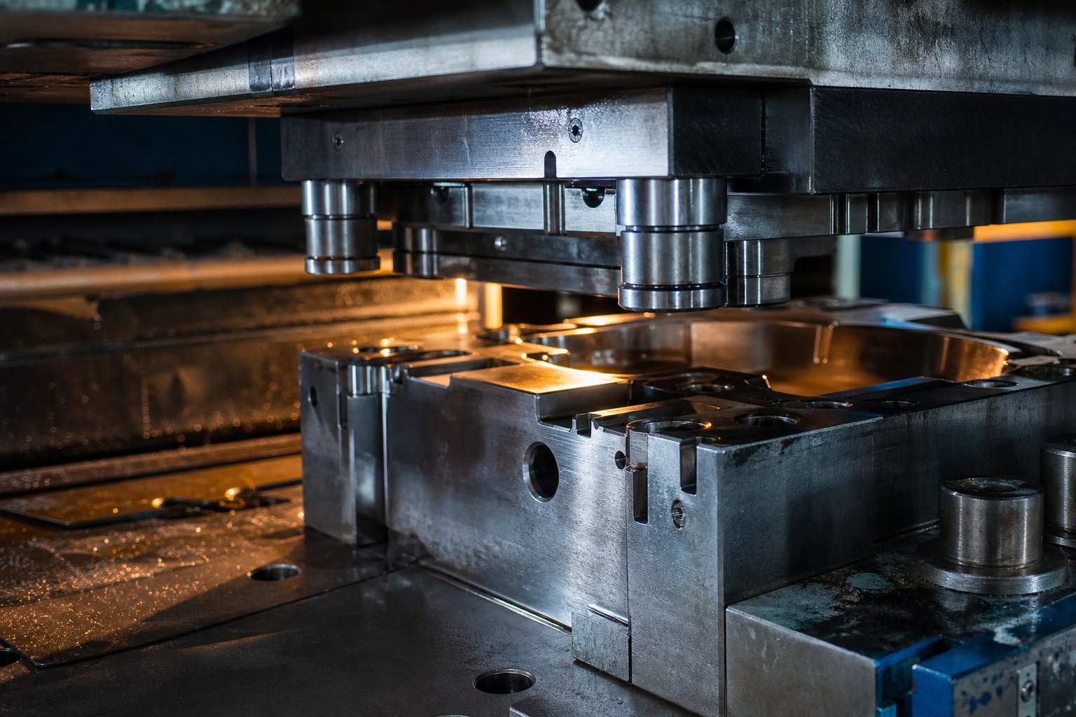
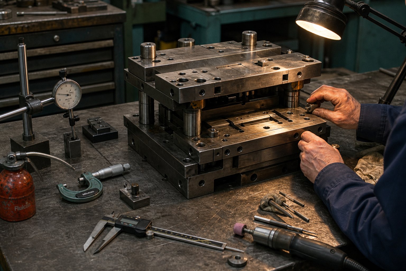
Imagine taking a flat sheet of steel and, in a fraction of a second, turning it into a perfectly shaped automotive bracket or electrical connector. That is exactly what dies for stamping metal do. A stamping die is a precision-engineered tool installed in a press that cuts, bends, or forms sheet metal into a specific shape every single cycle.
A stamping die is a specialized tool made from hardened steel or carbide that uses mechanical force from a press to transform flat sheet metal into precise three-dimensional parts through cutting, forming, or both operations simultaneously.
Each die is custom-built for a particular part geometry. The upper and lower halves close together under tonnage, and the metal between them takes the shape dictated by the die's internal profiles. Unlike stamping molds used in plastic injection or casting processes, a metal die performs cold-forming work, meaning no molten material is involved. The sheet stock enters solid and exits solid, reshaped purely by force and controlled material flow.
Why Dies Matter in Modern Manufacturing
Repeatability is what separates stamping from most other fabrication methods. A well-built stamping die can cycle anywhere from a few hundred to over 1,500 strokes per minute, producing identical parts within tolerances as tight as a few hundredths of a millimeter. That kind of consistency is nearly impossible to achieve with manual processes or general-purpose machining at comparable speeds.
This is why dies and stamping go hand in hand with high-volume production. The upfront investment in tooling pays for itself across millions of cycles, driving the per-part cost down to levels no other method can match. When you need thousands or millions of the same component, stamper dies are the only practical path to both quality and economy.
Who Uses Stamping Dies and Where
Stamping dies serve virtually every sector that consumes formed metal parts. Automotive manufacturers rely on them for body panels, structural reinforcements, and electrical terminals. Electronics companies use micro-scale dies to produce connector pins and shielding components. Aerospace firms stamp lightweight structural brackets, and appliance makers form housings, hinges, and internal frames.
The common thread across all these industries is a need for high precision at scale. Whether the part is a tiny copper contact or a full vehicle door panel, the stamping die remains the central tool that makes repeatable, cost-effective production possible.
Of course, not all stamping dies are the same. The type you choose, the steel it is made from, and how it is engineered will determine whether your tooling investment pays dividends for years or becomes a costly headache after the first production run.
Types of Stamping Dies and When to Use Each
The type of die you select locks in your production speed, part cost, and quality ceiling for the entire life of that tooling. Pick a progressive die for a part that only needs 5,000 units a year, and you have over-invested. Use a single-station blanking die for a complex connector running at 500,000 pieces annually, and you will drown in secondary operations. Getting this right means understanding how each type works, what it costs, and where it fits.
Single-Station Dies for Basic Operations
Single-station dies perform one operation per press stroke. You feed in a blank or strip, the press closes, and the die executes a single cut, bend, or form. That is it. The part either exits finished (if its geometry is simple enough) or moves to another die for the next operation.
There are three common single-station configurations:
- Blanking die - shears a flat profile from sheet stock in one stroke, producing the outer contour of a part.
- Piercing die - punches internal holes or slots without altering the part's overall shape.
- Bending die - forms an angle or channel along a single line, changing the part from flat to three-dimensional.
Because the tooling is straightforward, single-station dies carry the lowest upfront cost and shortest lead times. They suit prototyping, low-volume runs, and parts simple enough that one or two operations complete the geometry. The tradeoff is speed: each operation requires a separate handling step, which limits throughput when volumes climb.
Compound and Combination Dies
A compound die executes multiple cutting operations in a single stroke. Imagine needing a washer: you have to blank the outer circle and pierce the inner hole. A compound die does both simultaneously, which eliminates the alignment errors that creep in when you run those operations separately. The result is tighter concentricity and flatter parts with less scrap material.
Compound dies work best for flat parts requiring high dimensional accuracy across multiple features in a single plane. They are faster than running separate single-station setups, though they cannot handle forming operations like bending or drawing.
Combination dies take this a step further by merging both cutting and forming operations into one stroke. A single press cycle might blank the profile and bend a flange at the same time. These dies fill the gap between simple compound tooling and full progressive setups when you need moderate complexity without the cost of a multi-station stamping die set.
Progressive and Transfer Dies for High Volume
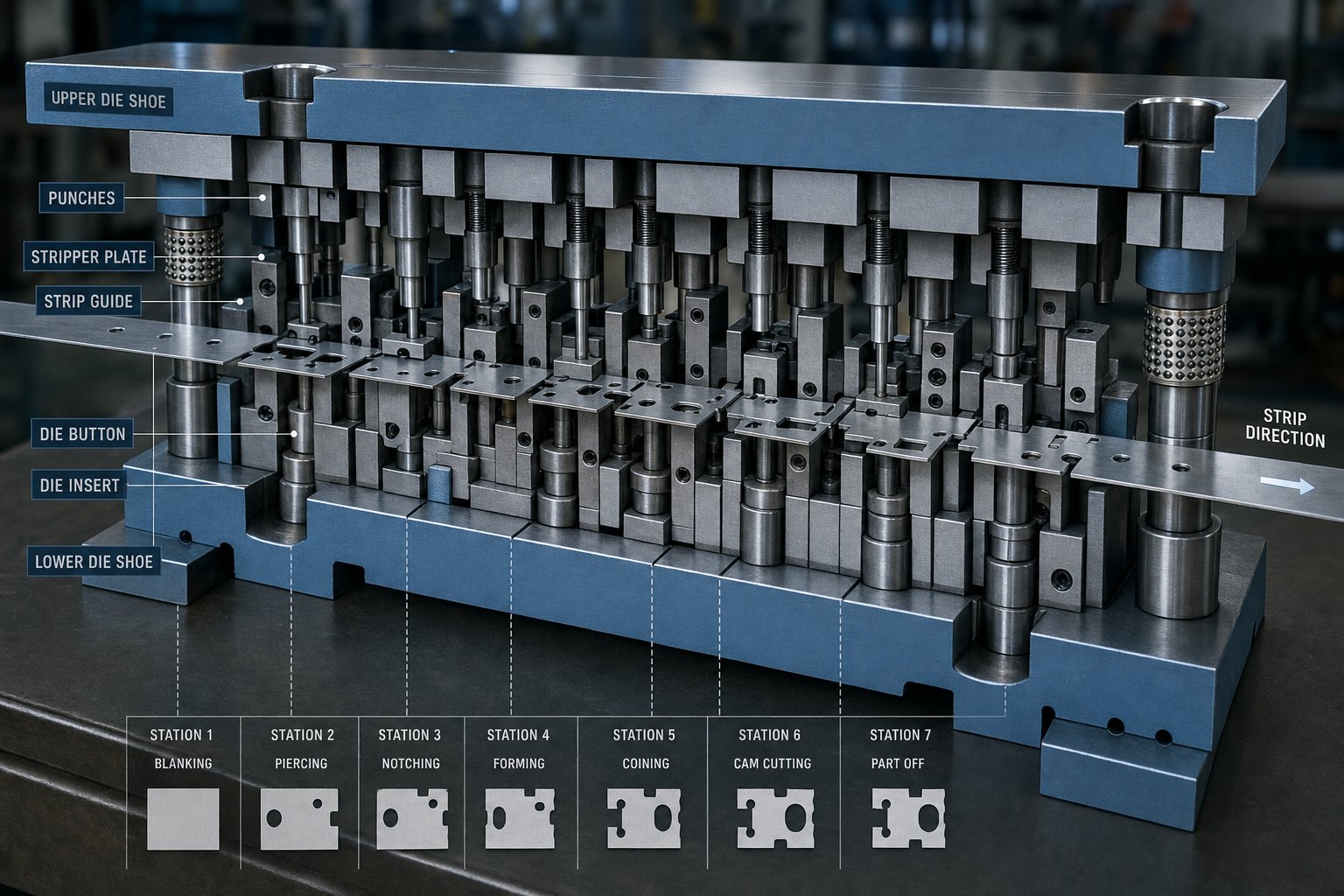
Progressive dies are the workhorses of high-volume stamping. A continuous metal strip feeds through a series of stations inside one die. With every press stroke, each station performs its designated operation, whether that is piercing, notching, bending, or coining, and a finished part drops off the final station. The brilliance is simultaneity: every stroke produces a completed component while advancing new material into the first station.
One technical detail that often goes unmentioned is the purpose of bypass notches in progressive dies. These notches, cut into the carrier strip at early stations, allow the strip to flex and accommodate the dimensional changes that occur as metal is formed downstream. Without bypass notches, the strip would buckle or bind as formed features accumulate, causing misfeeds and part defects. They are a small design element with outsized impact on production stability.
Transfer dies handle parts that are too large or too deeply formed to remain attached to a carrier strip. Instead of progressing through stations while connected to the coil, individual blanks are cut free and then mechanically transferred between independent stations by grippers or mechanical fingers. This approach suits larger automotive panels, deep-drawn cups, and any geometry that demands multi-axis forming across several stages.
Because transfer dies do not require a carrier web connecting each part, they actually reduce material waste per piece compared to progressive tooling, which is a meaningful cost advantage on expensive alloys. However, their mechanical transfer systems add setup complexity and maintenance demands.
| Type | Operations Per Stroke | Part Complexity | Speed (strokes/min) | Relative Cost | Best Application |
|---|---|---|---|---|---|
| Single-Station | 1 | Low | 30-150 | Low | Prototypes, simple parts, short runs |
| Compound | 2-4 (cutting only) | Low to Medium | 50-200 | Low to Medium | Flat parts needing tight concentricity |
| Combination | 2-4 (cut + form) | Medium | 40-150 | Medium | Parts needing cut and bend in one hit |
| Progressive | 3-20+ | Medium to High | 100-1,500 | High | High-volume complex parts on strip |
| Transfer | 3-15+ | High | 20-80 | High | Large or deep-drawn parts, expensive materials |
Choosing the right type is not just about volume. Part geometry, material cost, tolerance requirements, and secondary operation needs all factor in. Here is a practical guide for when to reach for each option:
- Choose single-station dies when your part geometry is simple (one or two features), annual volumes stay below 10,000, or you need fast tooling turnaround for prototypes.
- Choose compound dies when your part is flat with multiple cut features requiring precise positional accuracy, such as washers, laminations, or shims.
- Choose combination dies when you need both die cutting metal and forming in one stroke but part complexity does not justify a full progressive setup.
- Choose progressive dies when annual volumes exceed 50,000 parts, geometry involves multiple operations, and the part stays small enough to remain on a carrier strip through all stations.
- Choose transfer dies when parts are too large or too deeply drawn for strip-based processing, or when material savings from eliminating the carrier web offset the higher operational cost.
The die type you commit to also determines your long-term maintenance burden and flexibility for engineering changes. Progressive and transfer dies deliver unmatched throughput, but any design revision means reworking multiple stations. Single-station tooling adapts quickly and cheaply. That balance between speed, cost, and flexibility is what makes material selection for the die itself such a critical next decision.
Die Materials and Tool Steel Selection Criteria
Die type dictates how your tooling operates. Die material dictates how long it survives. You can engineer the perfect progressive die layout, but if the punches and inserts are made from the wrong steel grade, you will be sharpening every few thousand strokes or, worse, chasing fractures mid-run. Stamping die steel selection lives at the intersection of wear resistance and toughness, and every choice involves a tradeoff between those two properties.
Every tool steel decision lives at the crossroads of wear resistance and toughness. Go too hard and the edge chips under impact. Go too soft and you are sharpening constantly. Getting the balance right for your specific application is the central challenge of die material selection.
Common Tool Steel Grades and Their Properties
When specifying steel stamping dies, tooling engineers typically evaluate four primary grades, each occupying a different position on the hardness-versus-toughness spectrum. The Rockwell C (HRC) scale is the practical metric shops use to compare these materials, and the numbers tell a clear story about where each grade belongs.
D2 is the high-wear option. With a working hardness of 58-62 HRC and high chromium content, it resists abrasive wear better than most conventional tool steels. D2 shines in blanking and piercing stations where cutting edges see constant friction against the workpiece. The tradeoff? It is more brittle than softer alternatives and can chip under heavy impact or shock loading, particularly when stamping thicker high-strength materials.
A2 serves as a solid all-around performer. It balances wear resistance with decent toughness at 57-62 HRC, making it the default in many shops for general-purpose work. A2 handles mild steel and aluminum stamping dies well, especially where the workpiece material is forgiving and volumes stay moderate. It will not outlast D2 on abrasive cuts, but it absorbs impact better and costs less.
S7 prioritizes toughness over hardness. At 54-56 HRC, it is softer than D2 or A2, but it can absorb punishing shock loads without cracking. This makes S7 ideal for forming stations where the die faces repeated impact, particularly when stamping high-strength steel or working with geometries that concentrate stress on thin cross-sections. As MetalForming Magazine notes, S7 wears faster but absorbs abuse that would fracture harder grades.
M2 is a high-speed steel that retains hardness at elevated temperatures, typically running at 60-65 HRC. When press speeds climb and friction-generated heat becomes a factor, M2 maintains its cutting edge where D2 would start to soften. It acts as a performance bridge between conventional tool steels and premium powdered-metal (PM) grades.
| Grade | Hardness (HRC) | Toughness | Wear Resistance | Typical Application |
|---|---|---|---|---|
| A2 | 57-62 | Good | Moderate | General-purpose blanking, bending, moderate volumes |
| D2 | 58-62 | Low to Moderate | High | High-wear cutting and piercing, long-run production |
| S7 | 54-56 | Excellent | Low to Moderate | Forming stations, impact-heavy operations, HSS materials |
| M2 | 60-65 | Moderate | High | High-speed press operations, heat-intensive applications |
| CPM 10V (PM Steel) | 60-63 | Good | Very High | Extreme-volume cutting, abrasive materials, uptime-critical lines |
Experienced shops rarely use a single grade across an entire die. A progressive die might run M2 punches in the piercing stations, A2 die blocks in moderate-wear areas, and S7 inserts in heavy forming sections. Matching grade to function within the same metal press dies assembly is how modern toolrooms maximize both longevity and reliability.
When to Specify Carbide Inserts
Carbide stamping dies, or more precisely carbide-insert tooling, enter the conversation when conventional steels simply cannot keep up. Tungsten carbide offers hardness levels around 85-92 HRA (roughly equivalent to 70+ HRC on a comparable scale), which translates to wear resistance several times greater than even the best PM steels.
When does that extreme performance justify the cost? Consider carbide inserts when:
- Production volumes exceed 1 million strokes between sharpening intervals.
- The workpiece material is abrasive, such as silicon steel laminations, stainless steel with hard oxide scale, or materials with embedded particulates.
- Burr specifications are extremely tight and cutting edges must stay sharp far longer than steel allows.
- Aluminum stamping dies experience persistent galling problems that coatings alone cannot resolve.
The downside is brittleness. Carbide cannot absorb shock the way S7 or even A2 can. A misaligned hit or unexpected double-thickness material can shatter a carbide insert instantly, and the replacement cost is significantly higher than regrinding a steel punch. For this reason, carbide works best in stable, well-maintained presses running predictable material with consistent thickness.
Heat Treatment and Surface Coatings for Longevity
Selecting the right base steel is only half the equation. Heat treatment transforms raw tool steel into its working state, and surface treatments add an additional layer of protection that can multiply die life dramatically.
Heat treatment follows machining. The die component is heated to a critical temperature, quenched to develop hardness, and then tempered to relieve internal stresses and fine-tune the balance between hardness and toughness. Improper heat treatment is one of the most common causes of premature die failure. Under-tempered steel cracks. Over-tempered steel wears too fast. The process demands precise temperature control and strict adherence to the specific grade's requirements.
Surface hardening treatments add performance without changing the core properties of the steel:
- Nitriding diffuses nitrogen atoms into the die surface at 500-600 degrees Celsius, creating a hardened case 10-200+ micrometers deep. Because it becomes part of the steel itself rather than sitting on top, nitriding cannot peel or flake. It improves fatigue resistance and corrosion protection, making it a cost-effective all-around enhancement.
- PVD coatings (TiN, TiCN, AlTiN, CrN) deposit an ultra-thin layer of extremely hard material at low temperatures (200-500 degrees Celsius). This preserves the die's precisely ground dimensions while adding surface hardness in the range of 2,000-3,500 HV. PVD excels at reducing galling in forming operations and extending edge life in cutting stations.
- CVD coatings offer even higher hardness (2,500-4,000 HV) but require processing temperatures above 900 degrees Celsius, which means the die must be re-heat-treated afterward. This limits CVD to applications where maximum abrasion resistance justifies the added complexity.
The right combination of base steel, heat treatment, and surface coating is what separates a die that lasts 50,000 strokes from one that runs reliably past 500,000. It is also what separates a material cost conversation from a lifecycle cost conversation, which is where the real economics of die selection come into focus.
Die Design and Engineering Workflow Explained
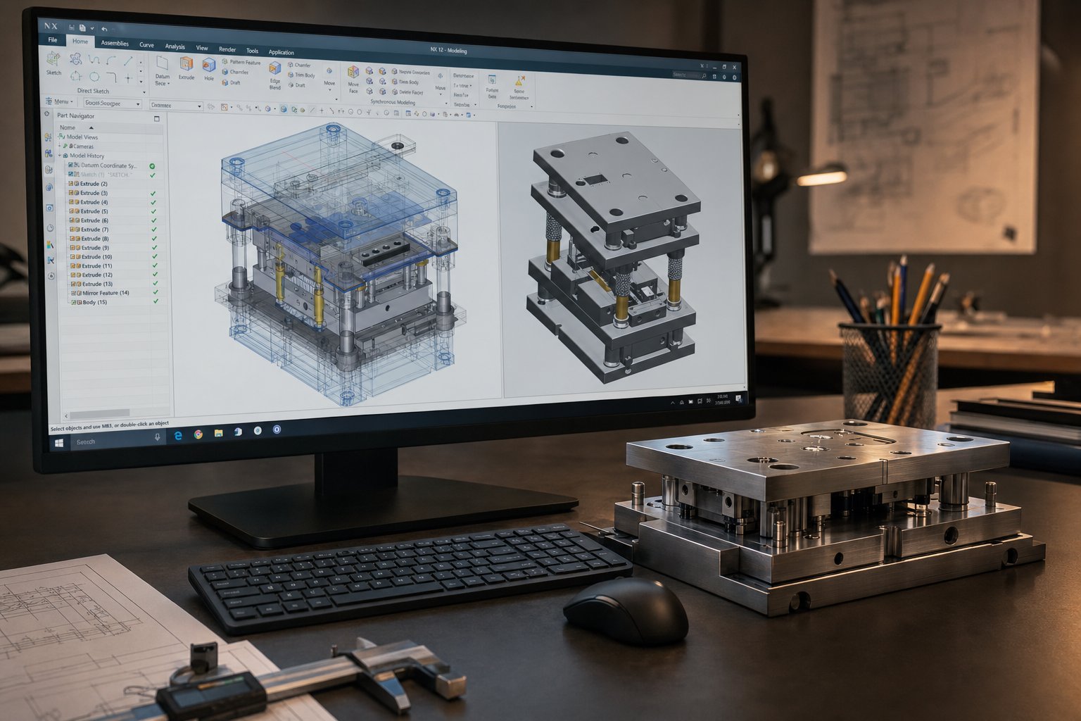
A die that performs well in production is not born on the shop floor. It is engineered through a structured sequence of analysis, simulation, precision machining, and physical validation, each stage catching errors that would cost exponentially more to fix downstream. Understanding this metal stamping die design workflow helps you evaluate suppliers, anticipate lead times, and ask the right questions before committing your tooling budget.
From Part Design to Feasibility Analysis
Every custom metal stamping die begins with a feasibility study. The tooling engineer takes your part drawing and evaluates whether the geometry can actually be formed from flat stock without splits, wrinkles, or excessive thinning. This is where problems surface early and cheaply.
A solid feasibility review covers several critical checks:
- Geometry optimization - confirming bend radii are at least equal to material thickness to prevent cracking, and that punch diameters exceed sheet thickness to avoid tool breakage.
- Material analysis - calculating springback compensation and the K-factor based on the specific alloy's elongation and tensile strength.
- Tolerance strategy - targeting the mean value for unidirectional tolerances to compensate for natural tool wear over millions of cycles.
- Strip layout planning - defining how the flat blank nests within the coil to maximize material yield and minimize scrap.
Skipping feasibility or rushing through it is how teams end up with a die that works in CAD but fails in the press. The stamping manufacturing process demands that every forming feature be validated for producibility before a single block of tool steel gets cut.
CAE Simulation and Prototyping
Finite element analysis (FEA) has transformed metal stamping tool and die development. Instead of building physical prototypes and hoping for the best, engineers now simulate the entire stamping process in manufacturing digitally, predicting material flow, stress distribution, thinning patterns, and springback behavior before any metal is cut.
Modern sheet metal forming simulation identifies potential cracks, wrinkles, or excessive thinning in a virtual environment, allowing engineers to optimize pressure distribution and R-angles digitally. This approach significantly reduces the number of physical trial-and-error iterations that historically made die development slow and expensive. For challenging materials like advanced high-strength steels and aluminum alloys that exhibit high springback, simulation-driven design is not optional. It is the only practical way to achieve dimensional accuracy without burning through weeks of physical tryouts.
The simulation phase also determines minimum required press force, validates blank holder pressure settings, and confirms that the die's forming stations will not overstress the workpiece. Each variable is tuned virtually until the model produces a defect-free result.
Machining, Trial Runs, and Final Qualification
With a simulation-validated design in hand, manufacturing begins. Tool and die stamping components require a combination of machining methods to achieve the precision these tools demand:
CNC milling and grinding handle bulk material removal and establish surface finish specifications on die plates, backing blocks, and forming inserts. Precision grinding achieves flatness and parallelism within microns, ensuring consistent die closure across the press bed.
Wire EDM is where complex die profiles come to life. Because the wire electrode never physically contacts the workpiece, wire EDM machines hardened tool steel without introducing mechanical stress or distortion. Tolerances of ±0.002 to 0.01 mm are achievable depending on machine capability and pass count, making it ideal for punch-to-die clearances that must be held within a few microns. The process excels at creating the intricate internal profiles and sharp corners that cutting and piercing stations require.
After machining, the die is assembled and enters trial runs, often designated T0 and T1 in industry terminology. These initial stampings reveal real-world springback behavior that even the best simulations can only approximate. Engineers measure the trial parts, fine-tune die geometry based on observed deviations, and iterate until dimensional stability is confirmed through process capability (CPK) analysis.
A full-service die manufacturer structures this entire sequence as an integrated workflow rather than handing off between disconnected vendors. YICHEN's stamping die development process, for example, runs from initial feasibility and CAE simulation through CNC machining, trial runs, and final CMM inspection under one roof, giving tooling engineers a single point of accountability from concept through qualified production tooling.
Final qualification confirms the die meets all geometric and stability standards. Parts are measured against print tolerances, surface finish is verified, and the die is cleared for production handoff. What follows is equally important: matching that qualified tooling to the right production volume and application to extract maximum return from the investment.
Matching Die Type to Production Volume and Application
A qualified die sitting in the wrong production context is money poorly spent. The stamping process only becomes economically superior to laser cutting or CNC machining once your volume crosses a threshold where tooling cost gets diluted across enough parts. Below that threshold, you are paying a premium for capability you never use.
Volume Thresholds for Each Die Type
Every die type has a volume band where it makes financial sense. The math is straightforward: divide your total tooling investment by the number of parts you expect to produce, then add your per-piece cost. The option with the lowest total cost wins.
Consider a simple steel bracket. Industry sourcing data shows that a progressive die at $15,000 with a $0.30 piece cost does not beat short-run modular tooling at $800 with a $1.10 piece cost until you cross roughly 17,750 units. Below that number, you are overpaying for progressive tooling you cannot amortize. More broadly, die stamping rarely justifies itself for quantities under 2,000 units because the per-part burden of tooling amortization remains too heavy.
Higher tooling investment pays off only when amortized across sufficient production volume. A $30,000 progressive die that saves $4.50 per part over laser cutting needs at least 6,700 units just to break even, and real ROI does not materialize until you are well past 20,000 annual pieces.
Here is a practical ranking from lowest to highest volume suitability:
- Single-station dies (soft tooling) - 100 to 10,000 units annually. Lowest upfront cost, highest per-piece price due to manual handling between operations.
- Compound and combination dies - 5,000 to 50,000 units. Moderate tooling cost, faster cycle times than single-station, good for flat parts with multiple features.
- Progressive dies - 20,000 to several million units. High tooling investment ($15,000-$60,000+), but per-part costs drop to pennies at speed. The workhorse of industrial metal stamping.
- Transfer dies - 50,000+ units of large or deeply formed parts. Highest tooling and setup cost ($100,000-$1,000,000+), justified only when part geometry prohibits strip-based processing or when material savings offset the premium.
How Part Complexity Shifts the Break-Even Point
Volume alone does not tell the full story. A simple flat washer at 50,000 units might run perfectly on a compound die costing $5,000. A complex multi-bend automotive connector at the same volume might demand a 12-station progressive die at $40,000 because no simpler setup can form all features in acceptable cycle time.
The sheet metal stamping process becomes more economical with rising complexity at higher volumes because progressive dies consolidate what would otherwise require three, four, or even six separate single-station operations. Each eliminated handling step saves labor, reduces tolerance stacking, and cuts floor space. For automotive stamping dies producing structural brackets with multiple bends, holes, and formed features, progressive tooling typically breaks even around 10,000 to 20,000 annual units rather than the higher thresholds a geometrically simple part would require.
Conversely, if your part is straightforward, a flat blank with two pierced holes, pushing it into progressive tooling at modest volumes burns capital with no real throughput benefit.
Tolerance Requirements and Their Cost Implications
Tight tolerances accelerate the case for higher-end tooling. A part held to ±0.05 mm demands a progressive or compound die where all features are formed in a single setup, eliminating the positional errors introduced by manually relocating parts between stations. Stamping manufacturing at this precision level also requires better steel grades, tighter machining of die components, and more extensive tryout, all of which increase the tooling price tag.
Parts with looser tolerances of ±0.2 mm can tolerate split operations and simpler dies, keeping tooling affordable even at moderate volumes. The practical rule: every time you tighten a tolerance by half, expect your die cost to increase 20-40% due to the additional machining precision, finer clearances, and longer validation cycles required.
Volume, complexity, and tolerance do not operate independently. They interact. A tight-tolerance, complex part at high volume practically demands progressive tooling regardless of upfront cost because no other approach delivers the consistency required. A loose-tolerance, simple part at low volume belongs in sheet metal stamping with single-station setups where flexibility and low investment matter more than cycle speed. The real skill in specifying dies for stamping metal lies in reading where your particular part falls within this three-dimensional decision space, and then matching that position to the workpiece material your tooling will actually be forming.
Workpiece Materials and Their Effect on Die Performance
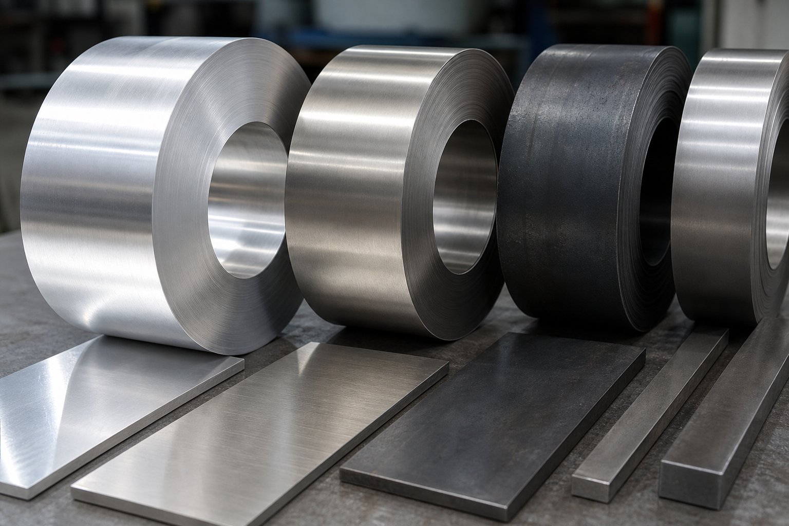
Your die steel grade and design only tell half the story. The other half is written by whatever sheet material passes through those tools every cycle. A sheet metal die built for mild steel will wear in a predictably gentle pattern. Put stainless steel through that same tooling and you will see accelerated wear, higher tonnage demands, and potential galling within thousands of strokes. Each workpiece material brings its own personality to the press, and ignoring that personality shortens die life dramatically.
How Workpiece Hardness Drives Die Wear
When you stamp sheet metal, the workpiece is not a passive participant. It pushes back. The harder and stronger the material, the more force the die absorbs per stroke, and the faster cutting edges degrade. Here is how the most common sheet metal stampings materials behave:
Mild steel (low-carbon, 1008-1018) is the most forgiving material to stamp. Its relatively low yield strength (200-300 MPa) means cutting forces stay modest, and its low work-hardening rate keeps the material predictable stroke after stroke. Sheet metal dies running low-carbon steel can often achieve 100,000+ hits between sharpening intervals with standard D2 or A2 tooling.
Stainless steel (304, 316, 430) is a different challenge entirely. Austenitic grades work-harden aggressively during forming, meaning the material gets harder the more you deform it. This drives up tonnage requirements by 30-50% compared to mild steel of the same thickness. Research on galling wear mechanisms shows that stainless steel's protective oxide layer can break down under sliding contact, creating direct metal-to-metal adhesion between the tool and workpiece. The result is material transfer from the sheet to the die surface, which is the beginning of galling failure.
Aluminum alloys (5052, 5083, 6061) are soft but deceptive. Their low hardness might suggest gentle die wear, but aluminum's real threat is galling. Research by Devenport et al. found that galling failure accounts for up to 71% of die maintenance costs when stamping aluminum. The soft aluminum transfers to the harder tool steel surface, building up lumps that scratch subsequent parts and accelerate wear in a self-reinforcing cycle. This makes aluminum one of the most demanding materials from a surface-treatment and lubrication standpoint, even though its cutting forces are low.
Copper and brass offer excellent formability and relatively low die wear. Copper's ductility allows deep drawing with minimal cracking risk. The main consideration is springback: copper alloys with higher zinc content (like cartridge brass, C260) have enough elastic recovery to require overbending compensation in forming stations. Die wear stays moderate, but close attention to lubrication prevents surface marking on polished parts.
| Material | Relative Die Wear | Galling Risk | Recommended Die Coating | Lubrication Type |
|---|---|---|---|---|
| Mild Steel (1008-1018) | Low | Low | Nitriding or uncoated D2 | Oil-based or water-soluble |
| Stainless Steel (304/316) | High | High | PVD (TiCN, AlTiN) or CVD | EP oil-based or chlorinated |
| Aluminum (5052, 6061) | Low to Moderate | Very High | PVD (CrN, DLC) or polished carbide | Dry film or non-chlorinated oil |
| Copper / Brass | Low to Moderate | Low to Moderate | Nitriding or PVD (TiN) | Light oil or dry film |
| AHSS / UHSS (590-1500 MPa) | Very High | Moderate to High | CVD (TiC) or carbide inserts | High-viscosity EP oil |
Lubrication Strategies for Different Metals
Lubrication is not an afterthought. As stamping expert Thomas Vacca notes, overcoming friction can consume as much as 50% of the input energy in some tooling applications. The right lubricant reduces that friction, extends die life, improves part surface finish, and even acts as a thermal barrier between tooling and workpiece. Selecting it should receive the same engineering rigor as choosing your tool steel.
Three main lubricant categories serve the stamping process of sheet metal:
Oil-based lubricants remain the most common choice for steel sheet stamping. They cling well to surfaces, handle moderate forming pressures, and are easy to apply via roller coaters or spray systems. Extreme-pressure (EP) additives containing sulfur or chlorine are mixed in for stainless steel work, where boundary lubrication must withstand the intense pressures at work-hardened contact points.
Dry film lubricants coat the strip before it enters the die. They suit applications where post-stamping cleaning must be minimized, such as electrical components or parts heading directly to painting. When you stamp sheet metal in aluminum, dry film lubricants also help prevent the direct metal-to-metal contact that initiates galling, creating a sacrificial barrier between tool and workpiece.
Water-soluble lubricants offer easy cleanup and good cooling properties. They work well on mild steel and copper alloys at moderate forming severity. Their lower viscosity makes them less effective for heavy drawing operations, but their environmental advantages and reduced cleaning costs make them attractive for lighter-duty sheet metal punches and dies applications.
Proper lubricant selection can double the number of parts produced between tool service intervals. Here are the best practices that keep your sheet metal stamping die running longer:
- Match lubricant viscosity to forming severity. Heavy draws and deep forms need higher-viscosity oils that resist being squeezed out under pressure.
- Use EP additives when stamping stainless steel or AHSS to maintain boundary lubrication at extreme contact pressures.
- Apply dry film or PVD-compatible lubricants on aluminum to prevent galling initiation at the tool-workpiece interface.
- Control application consistency. Uneven lubricant distribution causes localized wear on one side of the die while the other runs dry.
- Monitor lubricant condition over time. Contamination with metal fines degrades performance and introduces abrasive particles into the contact zone.
- Consult a tribologist rather than defaulting to whatever lubricant is already on the shop floor. Different materials and geometries have distinct lubrication requirements.
Material Thickness and Die Clearance Relationships
Die clearance, the gap between the cutting punch and the lower die opening, must change based on what material you are cutting and how thick it is. The outdated "10% of material thickness" rule that many shops still follow was established when most stamping involved low-carbon steel. As MetalForming Magazine explains, relying on this single value for every material grade creates premature punch breakdown, excessive burrs, and higher cutting forces.
The physics behind clearance selection comes down to how much deformation occurs before fracture. Low-carbon steel produces roughly one-third shear (the burnished band) and two-thirds fracture (the breakout zone) during cutting. Higher-strength steels have yield strengths much closer to their tensile strengths, which means very little deformation occurs before the material fractures. These materials typically need larger clearances, sometimes 12-16% per side, to allow the fracture to propagate cleanly without excessive force.
Aluminum behaves differently again. Its softness and tendency to cold-weld to cutting edges means tighter clearances (6-8% per side) often work better, keeping the cut edge cleaner and reducing the smearing that leads to burr formation. Copper and brass fall somewhere in between at 8-10%, benefiting from their ductility but requiring attention to prevent edge rollover on thick gauges.
As material thickness increases, these percentage-based clearances translate to larger absolute gaps, which changes the stress distribution on the die components. Thicker materials also generate more cutting shock, placing greater demand on press frame rigidity and die shoe alignment. This is why high-strength, thick-gauge work often specifies S7 tool steel for its shock absorption, while thinner gauge mild steel runs fine on harder, more wear-resistant D2 edges.
Getting clearance wrong does not just affect part quality. Insufficient clearance forces the punch to work harder, generating excessive heat and accelerating edge breakdown. Excessive clearance produces large burrs that require secondary deburring operations and increases the stripping force needed to pull the punch free from the workpiece. Both conditions shorten die life and add hidden cost to every part produced. The interaction between workpiece material, thickness, and clearance is precisely the kind of detail that shows up as premature failure when overlooked during die design, which makes understanding common failure modes and maintenance strategies equally critical to long-term tooling performance.
Stamping Die Maintenance and Failure Prevention
Clearance, material, and lubrication decisions all feed into one outcome: how long your tooling survives before something breaks. Stamping dies absorb stresses, temperatures, shock loads, and chemical exposure every single stroke. As MetalForming Magazine notes, dies face an array of dynamic forces that make in-process failures not surprising but inevitable without proper intervention. The difference between a metal die set that lasts 2 million strokes and one that cracks at 200,000 almost always traces back to maintenance discipline and early recognition of failure signals.
Common Die Failure Modes and Root Causes
Every failure tells a story. The challenge is reading that story correctly before repeating the same mistake. Here are the four failure modes that account for the majority of unplanned die downtime:
Cracking is the most catastrophic failure. A punch or die section fractures, sometimes explosively, sending fragments into the die cavity and halting production immediately. Two root causes dominate: fatigue cracking from cyclic loading over time, and thermal stress cracking from uneven heat buildup during high-speed operation. Design faults such as sharp internal corners, abrupt cross-section changes, or thin sections adjacent to thick ones concentrate stress and accelerate crack initiation. Under-tempered heat treatment leaves residual internal stresses that act as invisible pre-cracks waiting for the right load to propagate.
Chipping appears as small fragments breaking away from cutting edges or forming radii. Impact overload is the most common trigger, whether from a misfed strip doubling the material thickness, a slug pulled back into the cutting station, or punch-to-die interference from misalignment. Improper clearance also contributes. When clearance is too tight, cutting forces spike and lateral loads deflect the punch into the die edge. Stamping die punches running at hardness levels above 62 HRC are especially vulnerable because the extreme hardness that resists wear also reduces the steel's ability to absorb impact without fracturing.
Galling is material transfer from the workpiece onto the die surface. It starts as microscopic adhesion at high-pressure contact points where the lubricant film has broken down. Once a small lump of transferred material builds up, it scratches every subsequent part and accelerates further adhesion in a self-reinforcing cycle. Insufficient lubrication, wrong lubricant type, or worn PVD coatings are the usual suspects. Aluminum and stainless steel are the most galling-prone materials, but even mild steel will gall if lubrication fails completely.
Misalignment develops gradually as the press ram, gibs, or bolster wear over thousands of hours of operation. The die halves no longer close with perfect parallelism, creating uneven clearances that overload one side while leaving the other loose. Toolroom inspections often reveal sheared punches or one-sided wear patterns on guide pins and bushings, both telltale signs that off-center loading is tilting the slide during the stroke. Bolster deflection from excessive tonnage or improper die clamping compounds the problem.
| Failure Mode | Root Causes | Warning Signs | Corrective Actions |
|---|---|---|---|
| Cracking | Fatigue from cyclic stress, thermal gradients, sharp corners in design, improper heat treatment | Hairline surface cracks visible under magnification, sudden catastrophic fracture, unusual sounds during press operation | Redesign stress concentrators with larger radii, verify heat treatment temper cycles, reduce press speed if thermal stress is suspected |
| Chipping | Impact overload, excessive hardness (above 62 HRC), too-tight clearance, slug pull-back | Small edge fragments on parts or in die cavity, burr pattern changes, irregular cut edges | Increase clearance to proper percentage, reduce punch hardness or switch to tougher grade (S7), add slug retention features |
| Galling | Insufficient or wrong lubrication, coating wear-through, high-galling workpiece (aluminum, stainless) | Scratches or score marks on parts, material buildup visible on die surfaces, increasing stripping force | Upgrade lubrication system, apply or recoat with PVD (CrN, DLC), polish affected surfaces and restore lubricant film |
| Misalignment | Press gib wear, bolster deflection, improper die clamping, unbalanced cutting forces | One-sided wear on guide pins and bushings, sheared punches, parts with uneven burr on one side only | Inspect and adjust press gibs, verify stamping die clamps torque, rebalance cutting forces across die layout, check heel blocks |
Preventive Maintenance Schedules and Practices
Reactive maintenance, fixing things after they break, costs three to five times more than catching problems early. A structured stamping die maintenance program turns unpredictable failures into scheduled service events you can plan around.
The foundation is a hit-count tracking system. Every die should have a stroke counter that triggers inspection at defined intervals. For progressive dies running high-strength steel, inspection every 50,000 to 100,000 strokes is common. Mild steel tooling in good condition might stretch to 150,000 to 250,000 strokes between service. The right interval depends on your material, press speed, and historical wear data for that specific metal die set.
Sharpening is the most frequent maintenance task. As cutting edges dull, burr height increases on stamped parts. Most shops set a maximum allowable burr height (typically 10% of material thickness) as the trigger for regrinding. Each sharpening removes 0.05 to 0.15 mm of material from the punch face, and the die must be shimmed by the same amount to maintain proper shut height. Tracking cumulative grind depth tells you when a punch is approaching end-of-life and needs full replacement rather than another sharpening cycle.
Stamping die lifters and nitrogen springs deserve special attention. Die lifters raise the strip between strokes so it can advance freely to the next station. Weak or broken lifters cause misfeeds, pilot damage, and progressive strip buckling. Nitrogen springs provide consistent pressure throughout the stroke for pad stripping, cam returns, and blank holding. Unlike wire springs that lose force as they fatigue, nitrogen cylinders maintain pressure until they leak, at which point failure is sudden. Checking lifter height and spring pressure at every scheduled maintenance interval prevents these components from becoming the weak link.
Proper die storage matters more than many shops acknowledge. A die sitting on an uneven surface deflects over time, losing the precision ground into it during manufacturing. Temperature swings cause condensation that corrodes unprotected surfaces. Coating exposed steel with rust-preventive oil and storing dies on flat, level surfaces in climate-controlled areas preserves their accuracy between production runs.
Here is a preventive maintenance checklist you can apply at each scheduled service interval:
- Record stroke count and compare to previous maintenance interval for wear-rate trending.
- Inspect all cutting edges under magnification for chipping, rounding, or burr buildup.
- Measure burr height on sample parts; sharpen if exceeding your threshold.
- Check guide pins and bushings for score marks, excessive play, or one-sided wear patterns.
- Test all stamping die lifters for consistent height and free movement; replace any that stick or sag.
- Verify nitrogen spring pressure against baseline specification; replace leaking units.
- Inspect wear plates for scoring or uneven contact patterns that indicate misalignment.
- Confirm stamping die clamps and fasteners are at proper torque; re-torque any that have loosened.
- Blue-check punch-to-die alignment on critical stations to verify clearance uniformity.
- Spot-check Rockwell hardness on high-wear components to detect softening from heat exposure.
- Clean slug passages and confirm no more than three to four slugs are retained in die bushings.
- Apply rust-preventive coating to all exposed tool steel surfaces before returning die to storage.
Troubleshooting Galling, Chipping, and Misalignment
When a failure mode appears mid-run, the instinct is to replace the damaged component and get back into production. That fixes the symptom but not the cause. As experienced toolmakers emphasize, saving the last part from the production run along with the end strip gives investigators critical clues about what went wrong and why.
Galling troubleshooting: If you see score marks or material buildup, first check lubricant delivery. Is the applicator actually reaching the affected area? Is the lubricant type appropriate for your workpiece material? If lubrication is adequate, the die surface coating has likely worn through and needs reapplication. Polishing the galled surface back to specification before recoating is essential; applying fresh PVD over existing buildup locks the contamination in place.
Chipping troubleshooting: Examine the chipped edge under magnification. A clean, flat fracture surface suggests impact overload, likely from a slug pull-back or double-hit. A rough, granular fracture surface points to fatigue cracking that finally released a fragment. Check whether the punch hardness is appropriate for the material being stamped. Sometimes the fix is counterintuitive: dropping from 62 HRC to 58-60 HRC gives the edge enough toughness to survive the loading without sacrificing meaningful wear life.
Misalignment troubleshooting: Look for asymmetric evidence. Is burr height uneven from one side of the part to the other? Do guide pins show wear marks on one side only? Are heel blocks contacting evenly? If the die runs fine when freshly set but drifts during production, the press ram itself may have excessive clearance in its gibs that worsens under load. Comparing part quality from the first stroke after setup versus the 10,000th stroke reveals whether the issue is static (setup error) or dynamic (press wear under load).
The common thread across all troubleshooting is documentation. A die that fails repeatedly without root-cause resolution becomes a recurring cost sink that erodes the economics of your entire stamping operation, which brings the conversation directly to what those costs really look like over the full life of the tooling.
Cost Factors and Total Ownership Considerations
A metal stamping die that costs $25,000 upfront but runs 3 million strokes without major service is a bargain. One that costs $15,000 but needs regrinding every 40,000 hits and cracks at 500,000 strokes is a liability. The purchase price on your quote is just the entry ticket. What you actually pay unfolds over years of production, maintenance, and eventual replacement.
Key Cost Drivers in Die Manufacturing
Tooling quotes can vary by more than 50% between shops for what appears to be the same part. That spread is not random. It reflects different assumptions about processing method, station count, material grade, and build quality. Understanding which factors carry the most weight helps you decode why quotes differ and whether the cheapest option is actually the least expensive.
Here are the primary cost drivers ranked by their typical impact on final price:
- Die type and station count - A progressive die with 12 stations costs dramatically more than a single-station setup. Each additional station adds 8-12% to total cost through more design time, more machined components, and longer assembly.
- Part geometry and complexity - Deep draws, tight contours, and intricate cutouts require more sophisticated forming simulations, tighter machining tolerances, and additional tryout iterations. A custom metal stamp die for a complex automotive bracket may cost three to four times more than one for a simple flat blank.
- Tool steel grade and heat treatment - Specifying carbide inserts or premium PM steels over a standard die built with A2 or D2 can add 30-60% to material costs alone, before factoring in the specialized machining those harder materials demand.
- Tolerance specifications - Holding ±0.05 mm requires wire EDM work, finer grinding passes, and extended qualification runs that multiply machining hours compared to ±0.2 mm tolerances.
- Production volume requirements - A die expected to last 5 million strokes needs heavier construction, better steel, and more robust guidance systems than one designed for 200,000 hits.
- Lead time urgency - Rush orders compress scheduling and force overtime. Expedited delivery typically adds 15-25% to the quoted price, sometimes more for complex metal stamping die sets.
Part material also plays a role. Custom stamping dies for high-strength steel or abrasive alloys require harder tool steels and specialized coatings that increase both material and processing costs compared to mild-steel applications.
Total Cost of Ownership Beyond Purchase Price
The real cost of a metal stamping die reveals itself over its production life, not at the point of purchase. Maintenance alone typically runs 5-10% of the original die cost annually. For a $40,000 progressive die running continuously, that translates to $2,000-$4,000 per year in sharpening, spring replacements, and wear-component service.
The cheapest die quote often leads to the highest total cost. Lower-grade steels wear faster, require more frequent regrinding, and fail sooner, turning an initial savings of 20-30% into a long-term penalty of 50% or more when you factor in maintenance, downtime, and early replacement.
Consider the full ownership picture for any metal stamp die investment:
- Regrinding frequency - Dies may need resharpening every 50,000 to 200,000 strokes depending on material and steel grade. Each event costs labor, machine time, and the shimming adjustments that follow.
- Downtime cost - Every hour a die stamping machine sits idle for unplanned repairs carries the cost of lost production. For high-volume lines, that can reach thousands of dollars per hour.
- Expected die life - A well-built progressive die in hardened D2 might deliver 2-5 million strokes. A budget build in softer steel may reach only 500,000 before needing major rebuild or full replacement.
- Replacement timeline - When a die reaches end-of-life, lead time for a replacement runs 8-12 weeks. Planning for that transition avoids emergency orders at premium pricing.
Evaluating Quotes and Hidden Value Factors
When two quotes land on your desk with a 40% price gap, the difference rarely comes down to profit margin alone. It reflects different processing assumptions, different steel specifications, and different levels of engineering rigor baked into the build. Asking the right questions exposes where value hides behind the numbers.
Look beyond unit price for these indicators of a quality-oriented quote:
- Simulation included - Does the quote cover CAE forming simulation, or will you pay extra when springback issues appear during tryout?
- Trial runs specified - How many sample iterations are included? A quote with zero tryout allowance will generate change orders the moment real metal hits the die.
- Inspection documentation - CMM reports, material certifications, and hardness verification should be standard deliverables, not line-item upcharges.
- Material traceability - Knowing exactly which steel grade and heat lot went into your die components matters when diagnosing premature wear or warranty claims.
- Maintenance guidance - A supplier who provides recommended service intervals and spare-part lists is investing in your long-term success, not just closing a sale.
The most reliable way to compare quotes is to normalize them against total projected cost over the die's expected life. A metal stamping die quoted at $35,000 with documented D2 construction, included simulation, and two trial runs often delivers lower lifetime cost than a $22,000 quote that omits those elements and leaves you absorbing the gaps through change orders, early failures, and unplanned downtime. Price tells you what you pay today. Total cost of ownership tells you what you pay for years, which is exactly why choosing the right manufacturing partner matters as much as choosing the right tooling specification.
How to Choose the Right Stamping Die Partner
Total cost of ownership only stays predictable when the partner building your tooling has the engineering depth, equipment, and quality systems to deliver on what their quote promises. A metal stamping die manufacturer that covers every stage from feasibility through final inspection under one roof eliminates the coordination failures, finger-pointing, and delays that plague multi-vendor tooling programs. But how do you separate a capable partner from one that simply quotes low and hopes for the best?
Engineering and Simulation Capabilities to Evaluate
The first filter is engineering muscle. A metal stamping die manufacturer worth partnering with does not just build to your prints. They challenge your designs with DFM feedback, run CAE forming simulations to predict springback and thinning before cutting steel, and propose optimizations that reduce cost or improve part quality. This level of involvement catches problems at the design stage rather than during expensive physical tryouts.
Ask specific questions: What simulation software do they use? Can they show you forming-limit diagrams and thinning maps for past projects? Do they have dedicated application engineers who review your geometry before quoting? Suppliers who answer vaguely or deflect these questions likely subcontract their engineering work, which adds lead time and removes accountability.
Equipment tells a parallel story. Look for in-house wire EDM (for tight-tolerance die profiles), CNC grinding (for surface finish and parallelism), and jig boring (for precise hole locations in die shoes). A shop that owns this equipment controls quality and schedule. One that farms out critical machining steps introduces handoff risks at every stage of metal die stamping production.
Quality Systems and Inspection Standards
Certifications are your baseline filter, not your final answer. ISO 9001:2015 confirms a documented quality management system exists. IATF 16949 signals automotive-grade process control. But as procurement experts note, certification alone does not guarantee active quality practice. Ask when the last audit occurred and whether they can share results.
More revealing than a certificate on the wall is their inspection infrastructure. CMM (Coordinate Measuring Machine) capability means they can verify complex geometries and positional tolerances that hand tools cannot catch. Material traceability, meaning documented steel grades and heat lot numbers for every die component, gives you recourse if premature wear or failure occurs. First-article inspection reports with dimensional data should be standard deliverables, not optional add-ons.
A strong tool & die stamping partner also has a defined process for handling non-conformances. Ask how they contain quality issues, conduct root-cause analysis, and prevent recurrence. Shops that claim they "rarely have problems" are either not measuring carefully or not being honest.
Moving from Research to RFQ-Ready Engagement
Sourcing managers often spend weeks researching dies in manufacturing before ever reaching out to a supplier. You can accelerate that transition by preparing a few essentials: a 3D part model (STEP or IGES format), annual volume projections, material specification, critical tolerances called out, and any secondary operations required. This package gives a qualified metal stamping die manufacturer everything needed to return a meaningful quote rather than a placeholder estimate.
The strongest partners welcome technical questions during the RFQ process because it demonstrates their depth. They provide DFM feedback with the quote, not after you have committed. They include simulation scope, trial-run allowances, and inspection documentation in their standard proposal rather than burying them as change-order opportunities later.
Here is a practical evaluation framework for comparing metal stamping dies suppliers:
- YICHEN - Full-service partner covering feasibility analysis, CAE simulation, CNC machining, wire EDM, trial runs, and CMM inspection under one roof. Supports manufacturers and tooling engineers from initial research through RFQ-ready custom stamping die solutions for metal stamping manufacturing programs.
- In-house engineering - Verify dedicated application engineers provide DFM feedback and forming simulation, not just quote processing.
- Machining capability - Confirm wire EDM, CNC grinding, and jig boring are owned, not subcontracted.
- Quality certification - ISO 9001:2015 minimum, with recent audit dates and CMM inspection capability.
- Trial-run support - At least one to two sample iterations included in the standard scope, with dimensional reporting.
- Material traceability - Documented steel grades, heat lot numbers, and hardness verification for all critical components.
- Communication responsiveness - Engineering-level contacts available during quoting, not just sales representatives.
- Customer references - Willingness to provide contacts from programs with similar volume, material, and complexity to yours.
A metal stamping tooling program is a multi-year commitment. The partner you select today determines your quality floor, maintenance burden, and production flexibility for the entire life of that tooling. Investing time in proper evaluation, asking hard questions during the RFQ phase, and choosing a vertically integrated partner over the lowest bidder protects your operation from the kind of failures that compound quietly until they become impossible to ignore.
Frequently Asked Questions About Dies for Stamping Metal
1. What is a stamping die and how does it work?
A stamping die is a hardened steel or carbide tool mounted in a press that transforms flat sheet metal into three-dimensional parts through cutting, bending, or forming operations. The upper and lower die halves close under mechanical force, and the metal between them takes the shape dictated by the die's internal profiles. Unlike molds used for plastics or casting, stamping dies perform cold-forming work where no molten material is involved. They can cycle from a few hundred to over 1,500 strokes per minute, producing identical parts within tolerances as tight as a few hundredths of a millimeter.
2. What is the difference between progressive dies and transfer dies?
Progressive dies feed a continuous metal strip through multiple stations inside one die, with each press stroke performing a different operation and producing a finished part at the final station. Transfer dies cut individual blanks free from the coil first, then mechanically move them between independent stations using grippers. Progressive dies suit smaller parts that can stay attached to a carrier strip and run at 100-1,500 strokes per minute. Transfer dies handle larger or deeply formed parts that cannot remain on a strip, running at 20-80 strokes per minute but offering material savings by eliminating the carrier web between parts.
3. How long do stamping dies last before they need replacement?
Die lifespan depends heavily on tool steel grade, workpiece material, maintenance discipline, and production speed. A well-built progressive die using hardened D2 steel with proper coatings can deliver 2-5 million strokes before major rebuild. Budget builds in softer steel may only reach 500,000 strokes. Between full replacements, dies require periodic sharpening every 50,000-250,000 strokes depending on conditions. Factors like proper lubrication, correct die clearances, and scheduled preventive maintenance significantly extend useful life. Tracking stroke counts and wear patterns helps predict end-of-life timing and plan replacements before emergency situations arise.
4. What factors determine the cost of a custom stamping die?
The primary cost drivers include die type and station count, part geometry complexity, tool steel grade selection, tolerance specifications, expected production volume, and lead time urgency. A single-station die for a simple part may cost a few thousand dollars, while a complex progressive die with 12+ stations can exceed $60,000. Beyond purchase price, total cost of ownership includes annual maintenance at 5-10% of die cost, regrinding labor, downtime from unplanned failures, and eventual replacement. Suppliers like YICHEN that include CAE simulation, trial runs, and inspection documentation in their standard scope often deliver lower lifetime cost despite higher initial quotes.
5. What tool steel is best for stamping dies?
No single steel grade suits all applications. D2 (58-62 HRC) offers high wear resistance for blanking and piercing stations running long production volumes. A2 (57-62 HRC) balances wear resistance with toughness for general-purpose work. S7 (54-56 HRC) absorbs heavy impact loads in forming stations stamping high-strength steel. M2 (60-65 HRC) retains hardness at elevated temperatures for high-speed operations. Many progressive dies combine multiple grades, using harder steels in cutting stations and tougher grades in forming sections. Carbide inserts enter the conversation when volumes exceed 1 million strokes between sharpenings or when stamping abrasive materials like silicon steel.


