


What Is a Progressive Stamping Die and Why It Matters
If you're sourcing high-volume metal parts, you'll encounter the term "progressive die stamping" early and often. But what is a progressive die, exactly, and why does it sit at the center of nearly every serious production stamping conversation?
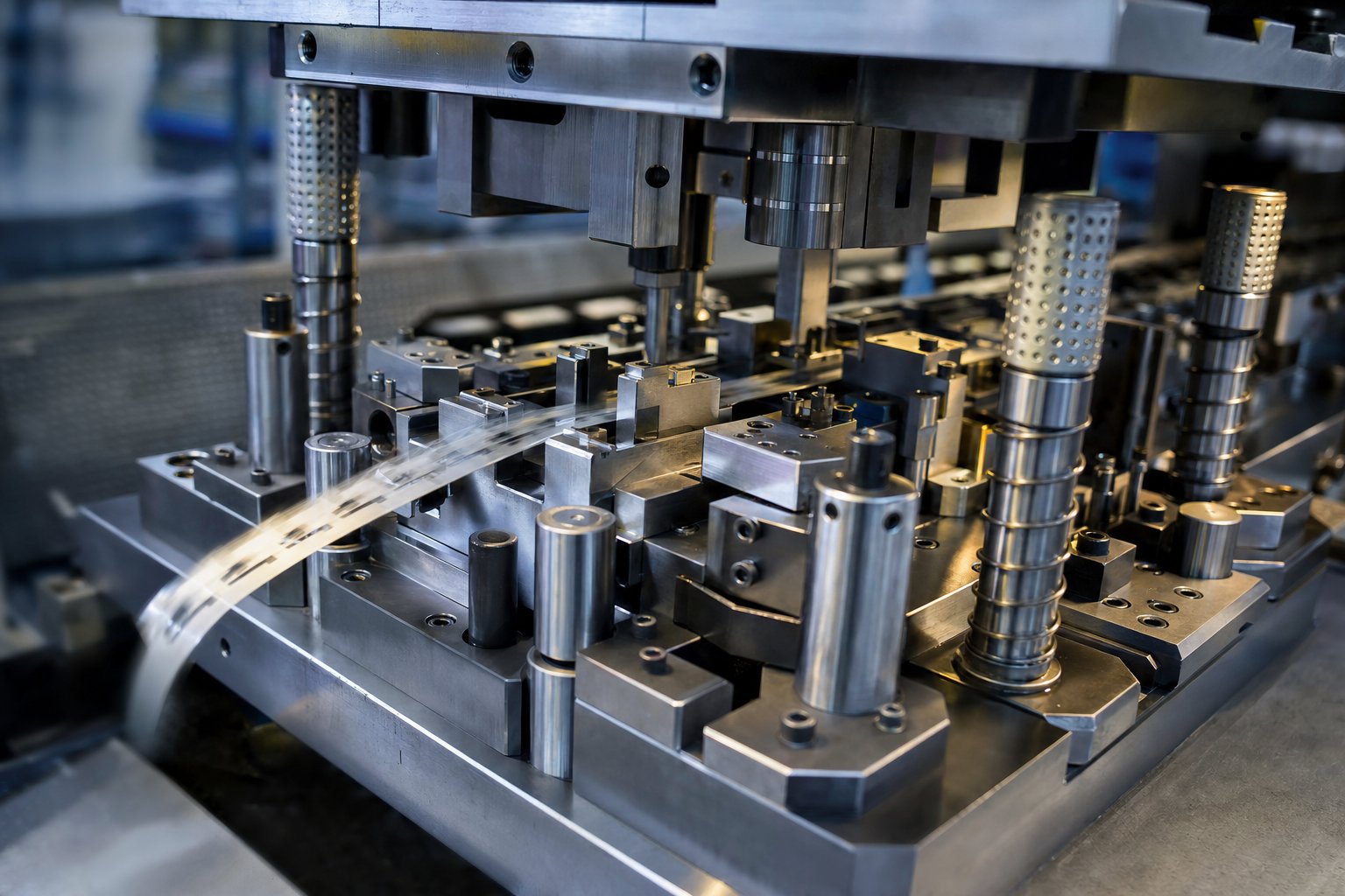
A progressive stamping die is a single tool containing multiple stations arranged in sequence. A continuous metal strip feeds through the die, advancing one fixed pitch with every press stroke. Each station performs a distinct operation - piercing, bending, forming, or cutting - so that a finished part drops off the end with every cycle of the press.
Defining the Progressive Die
Think of it as an assembly line compressed into one block of tool steel. Instead of moving a part between separate machines, the material itself travels through stations inside the die. The strip stays connected by carrier tabs until the final cutoff, which keeps everything aligned and eliminates manual handling between operations. A single-stage die, by contrast, performs just one operation per stroke - one bend, one hole, one blank. That simplicity works for prototypes or short runs, but it demands multiple setups and more labor to complete a complex part. Progressive stamping dies combine all those steps into one continuous cycle, producing a finished part with every stroke of the press.
Why Progressive Stamping Dominates High-Volume Production
The reason progressive die stamping dominates medium-to-high volume manufacturing comes down to three things: speed, repeatability, and material efficiency. Modern presses running progressive dies can achieve hundreds of strokes per minute, meaning thousands of identical parts per hour with minimal operator intervention. The millionth part off a well-maintained progressive die is dimensionally identical to the first. Material waste stays low because strip layouts are optimized to use as much of the coil width as possible.
For production engineers and procurement teams evaluating progressive stamping die manufacturers, understanding this process at a technical level is essential. It shapes every downstream decision - from quoting to quality expectations. The sections ahead break down exactly how material flows through a progressive die, station by station, and what that means for your part cost and timeline.
How the Progressive Die Stamping Process Works
A progressive stamping die looks deceptively simple from the outside - a heavy block of tool steel bolted into a press. But inside, dozens of precisely machined stations work in concert during every stroke. Understanding what happens at each station, and how the strip moves between them, gives you the technical foundation to evaluate part feasibility, ask better questions during quoting, and hold manufacturers accountable for quality.
Station-by-Station Operations Explained
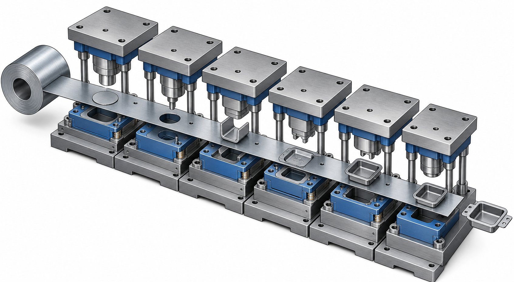
Imagine a coil of flat metal - steel, copper, aluminum - loaded onto an uncoiler and threaded through a straightener that removes coil set. The strip enters the progressive die and advances one precise increment, called the pitch, with every press stroke. Each station performs a specific forming or cutting operation on a different section of the strip simultaneously. Here's the typical sequence from entry to finished part:
- Pilot hole piercing: The first station punches small, precisely located pilot holes into the strip. These holes engage alignment pins (pilots) at downstream stations, ensuring the strip registers to within thousandths of an inch on every stroke.
- Blanking and piercing: Subsequent stations cut the profile outline and interior features - holes, slots, notches - removing material that won't be part of the finished component.
- Forming: Bending, drawing, or embossing operations shape flat sections of the strip into three-dimensional geometry. Depending on complexity, forming can span multiple stations to control material flow and avoid cracking.
- Coining: A high-pressure compression operation refines thickness in localized areas, sharpens features, or flattens surfaces to tight tolerances. Coining is common for parts requiring precise flatness or calibrated material displacement.
- Trimming: Excess material, tabs, or flash leftover from forming operations gets removed, cleaning up the part's final profile.
- Cutoff (separation): The final station severs the completed part from the carrier strip. The finished component drops into a bin or onto a conveyor, while the remaining skeleton strip ejects for recycling.
The critical insight here is simultaneity. While station six cuts off a finished part, station one is piercing pilot holes on a fresh section of strip, and every station in between is working on a different part at a different stage of completion. One press stroke, one finished part - every cycle.
Strip Layout and Material Flow
The strip layout is the engineering blueprint that makes all of this possible. Before any steel gets machined for the die, engineers use CAD software to design exactly how parts will nest on the strip, which operations happen at which stations, and how much material bridges between features to maintain carrier strip integrity throughout the process.
A well-designed strip layout balances several competing demands:
- Material utilization: Arranging part features to minimize scrap between components. Even a few percentage points of improved yield can save thousands of dollars across a million-part run.
- Carrier strength: The connecting tabs holding the part to the strip must be strong enough to pull it through every station without distortion, yet thin enough to separate cleanly at cutoff.
- Forming sequence logic: Operations must be ordered so that earlier cuts don't weaken areas needed for later bends, and formed features don't interfere with the strip's flat travel through downstream stations.
- Springback compensation: Engineers use FEA simulation to predict how the metal will elastically recover after forming and design deliberate overbend into the die geometry.
The strip layout is where progressive die and stamping expertise really shows. A less experienced shop might produce a functional layout; a skilled tooling engineer will produce one that runs faster, wastes less material, and requires fewer maintenance interventions over millions of cycles.
Stroke Rates and Production Speed
Speed is where progressive die metal stamping pulls away from every other forming method. Because the strip feeds continuously and all stations operate in parallel, the output rate equals the press stroke rate - one finished part per stroke.
Typical progressive stamping press speeds vary based on part complexity and material:
| Application Type | Typical Stroke Rate | Example Parts |
|---|---|---|
| Large brackets / structural components | 25–80 strokes per minute | Automotive brackets, HVAC housings |
| Mid-size connectors and terminals | 100–400 strokes per minute | Electrical contacts, clips, fasteners |
| Small precision components | 400–1,500+ strokes per minute | Micro-connectors, battery contacts, lead frames |
At the upper end, high speed metal stamping lines running small precision parts on dedicated presses - like Bruderer or similar high-speed platforms - can exceed 1,500 strokes per minute. That translates to over 2 million parts in a single 24-hour production day. Even at moderate speeds of 200 strokes per minute, a progressive stamping die produces 12,000 parts per hour with no operator touching the material between operations.
What keeps these speeds achievable isn't just the press - it's the entire system working together. Automatic coil feeders advance the strip with micron-level accuracy at every stroke. In-die sensors monitor strip position and forming forces in real time, stopping the press instantly if a misfeed or broken punch is detected. Lubrication systems apply precise amounts of stamping oil to reduce friction and heat buildup, which is especially critical in high speed metal stamping applications where thermal accumulation can distort parts or soften tooling edges.
This combination of parallel operations, continuous feed, and automated monitoring is what makes the progressive stamping die the production workhorse for any manufacturer targeting volumes in the hundreds of thousands or millions. But raw speed only matters if the parts come out right - and that depends heavily on how one die type compares to another for a given application.
Progressive Dies Compared to Alternative Die Types
Not every stamped part belongs in a progressive die. The geometry might be too large, the volume too low, or the forming too deep for a strip-fed process to handle efficiently. Knowing where progressive dies excel - and where they don't - saves you from over-investing in tooling that fights against the physics of your part.
Progressive Dies vs Transfer Dies
The biggest distinction between progressive dies and transfer dies comes down to how the workpiece moves through the process. In a progressive die, the part stays connected to the carrier strip from start to finish, only separating at the final cutoff station. In a transfer die, the blank is separated from the strip early and moved independently between stations by mechanical grippers or transfer fingers.
Why does this matter? When the part detaches from the strip, it can be rotated, flipped, or drawn deeply without the constraints of a connected carrier web. That makes transfer dies the better choice for larger components, deep-drawn geometries, and parts requiring operations on multiple sides. Transfer dies also save material - there's no carrier strip skeleton to scrap after production.
The tradeoff is speed. Transfer mechanisms can't match the stroke rates of a strip-fed progressive die, and the tooling setup is typically more complex. For small-to-midsized parts at high volumes with moderate draw depths, progressive die tooling wins on cycle time and per-part cost. For parts bigger than roughly 12 inches or requiring draw depths beyond what a connected strip allows, a transfer die is usually the right call.
Progressive Dies vs Compound and Tandem Dies
Compound dies perform multiple operations simultaneously in a single press stroke - cutting, piercing, and blanking all happen at once. They produce extremely flat parts with excellent concentricity between inner and outer features. Think washers, simple gaskets, and flat blanks where geometric accuracy in one plane is critical.
Sounds efficient? It is - for simple, flat parts. But compound dies can't form, bend, or create three-dimensional features. The moment your part needs a leg bent up, a tab coined down, or an embossed rib, you've exceeded what a compound die can do. Progressive dies handle that complexity while maintaining high throughput.
Tandem line dies (sometimes called line dies) take yet another approach: individual single-operation dies arranged in a row, each in its own press or press station, with automated transfer between them. You'll see tandem lines in heavy-gauge automotive panel stamping where each hit requires enormous tonnage and the parts are too large for a single progressive tool. The flexibility is high - you can rearrange or replace individual dies without scrapping the whole set - but floor space requirements, setup time, and capital cost are all significantly greater.
Single-stage dies, the simplest option, perform one operation per stroke. They're ideal for prototyping, short runs, or secondary operations on previously stamped parts. But for production volumes beyond a few thousand pieces, the labor and handling costs of running parts through multiple single-stage setups quickly exceed the tooling investment for a progressive tool and die solution.
Choosing the Right Die Type for Your Application
The decision isn't always obvious. A part with moderate complexity at 50,000 pieces annually might justify progressive die tooling for one manufacturer but not another, depending on material costs, tolerance needs, and available press capacity. Here's a side-by-side comparison to clarify the tradeoffs:
| Criteria | Progressive Die | Transfer Die | Compound Die | Tandem Line Die | Single-Stage Die |
|---|---|---|---|---|---|
| Volume Suitability | High (100K+ parts/year) | Medium to High (10K–500K+) | Medium to High (simple parts) | Medium to High (large panels) | Low (prototypes, short runs) |
| Part Size Range | Small to mid-size (up to ~12") | Medium to large (6" to 36"+) | Small to medium (flat only) | Large (automotive panels, structural) | Any size |
| Complexity Capability | Moderate to high (bends, forms, piercing) | High (deep draws, multi-axis forming) | Low (flat, single-plane operations) | High (heavy forming, large draws) | Single operation only |
| Typical Tooling Cost | $30K–$250K+ | $50K–$500K+ | $10K–$60K | $100K–$1M+ (full line) | $2K–$20K per die |
| Ideal Use Cases | Electrical contacts, brackets, clips, terminals | Deep-drawn housings, large enclosures, tubes | Washers, flat blanks, simple gaskets | Automotive body panels, heavy structural parts | Prototyping, secondary ops, very low volume |
A few practical rules of thumb: if your part is flat and simple, start with a compound die. If it's large, deep-drawn, or needs operations on both sides, look at transfer tooling. If it's a heavy-gauge panel measured in feet rather than inches, a tandem line makes sense. And if your part is small-to-midsized, geometrically complex, and needed in volumes where per-piece cost matters more than upfront investment - progressive dies are almost always the answer.
The stamping tool and die type you select determines not just part cost, but which manufacturers can realistically serve you. A shop specializing in progressive dies may not own the tonnage or bed size for transfer work, and vice versa. That reality becomes especially important when industry-specific requirements - material certifications, traceability, cleanroom protocols - further narrow your options.
Industry-Specific Requirements That Shape Manufacturer Selection
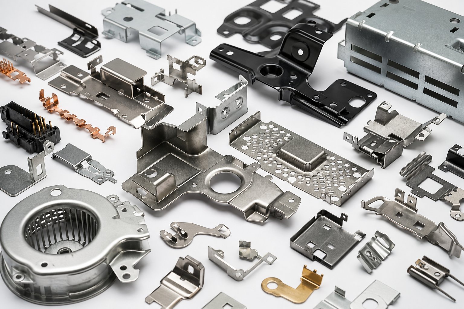
A progressive die is a progressive die, right? The physics of strip feeding and station-based forming don't change between industries. But the requirements surrounding those operations - tolerances, certifications, material traceability, cleanliness standards - vary so dramatically that a manufacturer perfectly suited for one sector may be entirely wrong for another.
Automotive and Transportation Requirements
Automotive components progressive stamping demands a combination of tight dimensional control, massive volumes, and rigorous process documentation. Connectors, terminals, brackets, and structural clips all require positional tolerances that can drop to 0.005mm on critical features. At annual volumes often exceeding several million pieces, even small deviations in die pitch or material springback compound into significant scrap rates.
Manufacturers serving this space need IATF 16949 certification and must execute APQP (Advanced Product Quality Planning) and PPAP (Production Part Approval Process) protocols. You'll also encounter requirements for lot-level traceability, statistical process control charting, and guaranteed CPK values above 1.33 on critical dimensions. A shop without these systems in place simply can't qualify as an automotive tier supplier, regardless of how well they cut steel.
Medical Device and Electronics Precision Standards
Medical progressive stamping introduces an entirely different layer of complexity. Parts destined for implantable devices, drug delivery systems, or surgical instruments must meet ISO 13485 quality management standards and often require biocompatible material certifications. Traceability goes beyond the lot level - some applications demand serial-number-level tracking from raw coil through finished part. Cleanroom or controlled-environment manufacturing may also be required to prevent particulate contamination on parts that contact bodily fluids.
Electronics stamping shares the medical sector's emphasis on micro-precision but adds unique material challenges. Copper progressive stamping - using phosphor bronze, beryllium copper, or oxygen-free copper alloys - requires tooling optimized for softer, more gummy materials that behave very differently from carbon steel under punch loads. Plating compatibility matters too: parts destined for gold, tin, or nickel plating need burr heights controlled to single-digit microns so coatings adhere uniformly without bridging across features.
- Automotive: IATF 16949, APQP/PPAP, CPK reporting, material certifications per OEM specifications
- Medical devices: ISO 13485, biocompatibility testing (ISO 10993), device master records, validated processes
- Electronics: IPC standards compliance, RoHS/REACH material declarations, plating adhesion specifications
- Defense/Aerospace: AS9100 certification, DFARS-compliant material sourcing, full lot traceability, controlled documentation
- HVAC/Industrial: UL/CSA component recognition, salt spray corrosion testing, material thickness verification per ASTM standards
HVAC and Industrial Applications
HVAC progressive stamping occupies the opposite end of the precision spectrum from medical or electronics work - but that doesn't make it simple. Large bracket stamping, mounting plates, fan housings, and heat exchanger components are typically formed from carbon steel progressive stamping materials in gauges from 1mm to 3mm or heavier. The priorities shift toward cost-per-part optimization, corrosion resistance through material selection or post-stamping coatings, and structural durability over millions of thermal cycles.
Manufacturers serving this sector need high-tonnage presses with large bed sizes, robust tooling designed for heavy-gauge materials, and efficient scrap management systems to keep progressive metal stamping costs competitive. Tolerances are looser than electronics or medical - typically plus or minus 0.1mm to 0.2mm - but the sheer material forces involved demand different engineering expertise than micro-precision work.
Defense and aerospace applications layer additional documentation requirements onto whatever precision level the part demands. Material certifications must trace back to the mill with full chemical and mechanical property verification. Lot control, first-article inspection reports, and controlled-revision drawing management are non-negotiable. A shop without AS9100 certification or familiarity with DFARS material sourcing requirements will struggle to pass supplier qualification audits.
The takeaway for buyers: don't assume that a manufacturer excelling in one sector automatically transfers that capability to another. A shop running high-speed copper alloy connector dies at 1,200 strokes per minute may have no experience with the heavy forming and corrosion testing that carbon steel progressive stamping for HVAC requires. Conversely, a manufacturer optimized for large industrial brackets may lack the micro-precision tooling and cleanroom infrastructure needed for medical progressive stamping. Match the manufacturer's proven industry experience to your actual application - not just their machine list.
The Progressive Die Engineering and Development Process
Selecting the right manufacturer based on industry fit is only part of the equation. What happens between signing a purchase order and receiving production parts can take months - and the engineering decisions made during that window determine whether your progressive stamping tool runs flawlessly for millions of cycles or struggles through endless adjustments on the press floor.
Most buyers never see this phase in detail. They submit a part drawing, receive a quote, and wait for samples. But understanding the progressive stamping die design process gives you leverage: you'll know when to push back, when to approve, and which milestones signal that your tooling partner has genuine engineering depth versus a cut-and-try approach.
Design and Simulation Phase
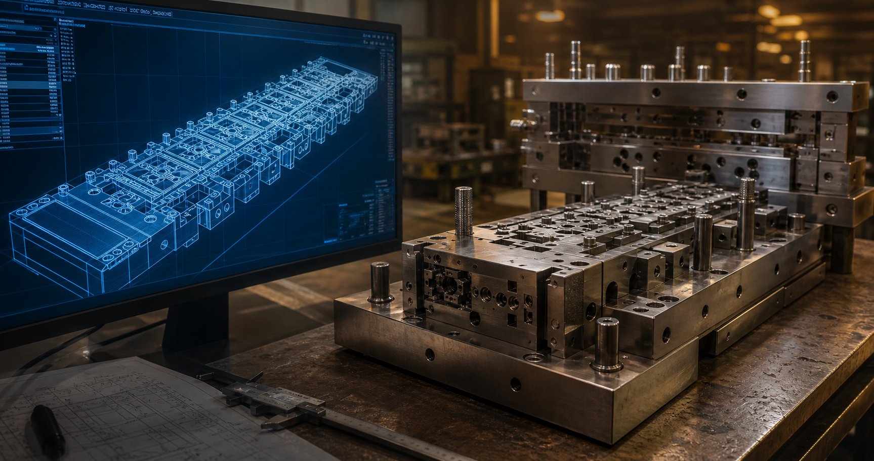
Every progressive die starts as a strip layout - a 2D or 3D CAD model showing exactly how the part nests on the coil, which operations happen at each station, and how the carrier strip connects everything together. Engineers use CAD/CAM platforms to define punch geometries, die clearances, pilot locations, and forming sequences before any steel gets cut.
Here's where capable manufacturers separate themselves: they run finite element analysis (FEA) simulation on the proposed design. Tools like incremental forming simulation software - including platforms such as AutoForm ProgSim - let engineers virtually try out the die on a computer. The simulation predicts material thinning, wrinkling risk, springback angles, and required forming tonnage at each station. It even auto-adjusts pressure pad forces when it detects potential wrinkle formation.
Why does this matter to you as a buyer? Because simulation-driven progressive stamping die design catches problems that would otherwise surface weeks later during physical tryout - when fixing them means regrinding hardened tool steel or scrapping entire die sections. As MetalForming Magazine notes, designers often have maximum freedom early in the process but minimal manufacturing knowledge, and that gap narrows rapidly once hard tooling is underway. Simulation closes this knowledge gap before money is committed to steel.
During this phase, you should expect to review and approve:
- Strip layout drawings showing part orientation, station sequence, and material utilization percentage
- FEA results highlighting any forming risk areas (splits, wrinkles, excessive thinning)
- Springback compensation strategy for bends and forms
- Preliminary tonnage estimates and press selection
- Progressive stamping materials confirmation - alloy grade, temper, thickness, and coil width
Prototyping and Die Tryout
With the design validated virtually, die components get manufactured using CNC milling, wire EDM, and precision surface grinding. Modern wire EDM machines cut complex punch and die profiles to tolerances within 0.005mm, while CNC high-speed milling handles 3D forming surfaces and die shoe pockets. Heat treatment hardens critical components to 58-62 HRC, and finish grinding brings everything to final dimensions.
Die tryout is where the progressive tooling meets reality. The assembled die goes into a tryout press, and the manufacturer runs sample strips at low speed, incrementally increasing stroke rate while inspecting parts at each stage. Engineers check:
- Dimensional accuracy against part print tolerances
- Burr height and edge condition on pierced features
- Bend angles and springback against nominal specifications
- Strip feeding consistency and pilot engagement
- Forming surface finish and any signs of galling or material pickup on tooling
Expect multiple tryout iterations. Even with simulation, minor adjustments are normal - shimming a form punch by 0.05mm, relieving a tight clearance, or tweaking a pilot hole position. A manufacturer who claims zero tryout iterations is either oversimplifying or running extremely simple parts. What matters is how quickly they converge on a stable process.
First-article samples from tryout get submitted to you for dimensional approval - typically via a FAIR (First Article Inspection Report) or PPAP package depending on your industry. This is your final gate before production authorization.
Typical Lead Times From Concept to Production
One of the least-discussed aspects of progressive tooling programs is timeline. Buyers often receive vague estimates and then face delays without understanding where the time actually goes. Here's a realistic breakdown:
| Phase | Typical Duration | Key Activities |
|---|---|---|
| Design and simulation | 3-5 weeks | Strip layout, FEA, design review, buyer approval |
| Die manufacturing | 6-10 weeks | CNC machining, wire EDM, heat treatment, grinding, assembly |
| Tryout and sampling | 2-4 weeks | Initial tryout, adjustments, sample submission, buyer approval |
| Production validation | 1-2 weeks | Run-at-rate, SPC data collection, final sign-off |
| Total | 12-20 weeks |
Complex dies with tight tolerances or many forming stations tend toward the longer end. Simple bracket tooling with four or five stations can hit the shorter timelines. A late-stage design change after die manufacturing begins can cost as much as half the original tool price and add weeks to the schedule - which is why design freeze before steel cutting is critical.
Modern manufacturing technology has compressed these timelines compared to a decade ago. High-speed CNC machining centers remove material faster. Wire EDM runs unattended overnight. Simulation catches issues that previously required multiple physical tryout-and-rework cycles. Together, these advances have improved first-article success rates and reduced the number of tryout iterations from an industry average of four to five rounds down to two or three for well-simulated progressive stamping tool programs.
For buyers, the practical implication is straightforward: ask your manufacturer what simulation tools they use, how many tryout iterations they typically need, and whether their quoted lead time includes production validation or just first samples. Those answers reveal more about engineering capability than any equipment list ever will - and they directly predict how your die will perform once it reaches full-speed production.
Precision Capabilities and Equipment That Define Quality
Engineering rigor during die development sets the foundation - but what ultimately determines part quality day after day is the precision of the equipment running that die. Two manufacturers can build an identical strip layout, yet produce parts with measurably different dimensional consistency depending on their press platforms, feed systems, and monitoring technology. When you're evaluating a potential partner, these hardware and process details tell you whether their shop floor can actually deliver the numbers their engineering team promises.
Tolerance Capabilities Across Materials
Every material behaves differently under progressive die operations. Copper alloys flow easily but spring back unpredictably on tight bends. Stainless steel work-hardens quickly and demands higher punch forces. Aluminum galls against tooling surfaces if lubrication isn't precisely managed. These behaviors directly affect the achievable tolerances - and the best manufacturers know which ranges are realistic for your specific material and feature combination rather than quoting a blanket number for every job.
High precision metal stamping can achieve tolerances as tight as ±0.025mm (±0.001 inches) on critical features like hole positions and form dimensions. For aerospace and medical applications, some operations push into the ±0.0127mm (±0.0005 inches) range with specialized tooling and controlled-environment production. But those extremes aren't universal - they depend on material type, thickness, feature geometry, and how many stations the strip passes through before reaching that operation.
Here's a practical reference showing what precision die stamping typically achieves across common materials and feature types:
| Feature Type | Carbon Steel | Stainless Steel | Copper/Bronze Alloys | Aluminum |
|---|---|---|---|---|
| Hole location (pierced) | ±0.05 mm | ±0.05 mm | ±0.03 mm | ±0.05 mm |
| Hole diameter | ±0.025 mm | ±0.038 mm | ±0.025 mm | ±0.038 mm |
| Bend angle | ±0.5° | ±1.0° | ±0.5° | ±1.0° |
| Flatness (over 25 mm span) | ±0.05 mm | ±0.08 mm | ±0.05 mm | ±0.08 mm |
| Profile/trim dimensions | ±0.05 mm | ±0.08 mm | ±0.05 mm | ±0.08 mm |
| Coined features | ±0.01 mm | ±0.02 mm | ±0.01 mm | ±0.02 mm |
Notice that stainless steel and aluminum tend toward looser bend tolerances. That's not a tooling limitation - it's material behavior. Stainless springs back more aggressively due to higher yield strength, and aluminum's low elastic modulus makes precise angular control more difficult without secondary coining operations. A manufacturer quoting ±0.25 degrees on a stainless bend without explaining their compensation strategy should raise questions.
Press Specifications That Impact Part Quality
The stamping press isn't just a frame that goes up and down. Its specifications directly determine what parts you can produce and how consistently they'll come out. When evaluating a manufacturer's equipment list, focus on these parameters:
- Tonnage: The maximum force the press can deliver at bottom dead center. Under-tonnage leads to incomplete forming and dimensional variation. A press running at 80%+ of rated capacity on every stroke will fatigue faster and drift sooner than one running at 60%.
- Bed size: Determines the maximum die footprint. A die that barely fits the bed leaves no room for nitrogen springs, scrap chutes, or in-die sensors - all things that affect quality at speed.
- Stroke length: Must accommodate the deepest form in the die plus adequate strip clearance for feeding. Too short a stroke means the die can't fully open for reliable strip advancement.
- Speed capability: Rated in strokes per minute (SPM). A high-speed stamping press built for precision work at 800-1,500 SPM has entirely different frame stiffness, bearing design, and dynamic balance characteristics than a general-purpose press rated for 60 SPM.
- Feed accuracy: The servo feed or mechanical feed system advancing the strip must maintain pitch accuracy within ±0.01mm stroke after stroke. At 1,000 SPM, that feed mechanism is indexing the strip over 16 times per second - any inconsistency compounds into positional errors across every downstream station.
High speed progressive die stamping at the upper end of performance relies on purpose-built press platforms. Bruderer's BSTL 350-88, for example, delivers 350 kN of force with a bed size of 870 x 536 mm and operates at speeds from 100 to 1,200 strokes per minute. Its drive-lever system distributes ram loads across the frame for consistent precision at speed, and an OPC UA interface connects to peripheral monitoring systems for full process transparency. Presses in this class feature minimum-clearance engineering and friction-reducing lubrication systems that maintain dimensional accuracy even during extended high speed stamping production runs.
What does this mean in practical terms? At 1,200 SPM running a connector die, a single press produces over 1.7 million parts per day. The per-part cost drops dramatically compared to a general-purpose press running the same die at 200 SPM - not just because of raw throughput, but because high-speed stamping press platforms maintain tighter process control at speed, generating less scrap and fewer out-of-tolerance parts that require sorting or rework.
In-Die Monitoring and Quality Assurance
Running a progressive die at hundreds of strokes per minute means problems develop fast. A broken punch at 800 SPM produces 13 defective parts per second before an operator even notices something sounds wrong. That's why in-die monitoring has become non-negotiable for any serious production environment.
Modern progressive dies incorporate multiple sensor types embedded directly in the tooling:
- Force sensors: Piezoelectric load cells mounted beneath forming stations detect changes in punch force that signal tool wear, material variation, or broken components. A sudden drop in force means a punch snapped. A gradual increase means the die is wearing and needs maintenance.
- Missfeed detection: Proximity or optical sensors confirm that the strip has advanced the correct pitch before the press completes its stroke. If the strip didn't feed - or fed short - the press stops before the die closes on a mispositioned blank.
- Part-out sensors: Confirm that each finished part has ejected from the die before the next stroke. A part stuck in the die that gets double-struck can damage tooling costing tens of thousands to repair.
- Slug detection: Verify that blanking slugs have fallen clear of the die. Retained slugs cause surface defects and can crack punches on subsequent strokes.
Beyond in-die sensing, automated inspection systems downstream of the press use vision cameras, laser measurement, and eddy current testing to verify critical dimensions on 100% of parts at production speed. This isn't sampling - it's every single piece checked against tolerances before reaching the packaging station.
For buyers, the question to ask isn't "do you inspect parts?" - every manufacturer says yes. The real question is whether they run in-die sensing with automatic press stop, and whether they perform 100% inline inspection versus periodic sampling. The difference determines whether a tooling failure produces 13 bad parts or 13,000 before someone catches it.
These precision capabilities and monitoring systems represent the hardware side of quality. But hardware alone doesn't guarantee results - the manufacturer operating that equipment needs the right processes, experience, and communication practices to deliver consistently. That evaluation requires looking beyond the machine list entirely.
How to Evaluate and Select Progressive Die Manufacturers
Equipment specs and tolerance tables tell you what a manufacturer can do in theory. But will they actually deliver consistent results on your project, at your volumes, within your timeline? That's a different question - and answering it requires evaluating progressive die manufacturers on process maturity, communication habits, and supply chain fit, not just machine lists.
Imagine you've narrowed your search to three or four stamping die manufacturers who all claim similar capabilities. How do you separate the genuinely capable partners from the ones who'll quote aggressively and then struggle through endless tryout iterations? The framework below gives production engineers and procurement teams a structured way to assess progressive die stampings suppliers before committing tooling dollars.
Green Flags That Signal a Quality Partner
Certain indicators consistently correlate with manufacturers who deliver on time, hit tolerances from the first production run, and communicate proactively when issues arise. When you're evaluating a progressive die manufacturer, look for these signals:
- Simulation-driven die design: They use FEA and forming simulation software (AutoForm, DEFORM, or equivalent) to validate strip layouts before cutting steel. This means fewer tryout iterations and faster time to production.
- In-house toolroom with full machining capability: CNC milling, wire EDM, surface grinding, and heat treatment all under one roof. A manufacturer who outsources critical die components loses control over quality and timeline.
- Documented tryout and validation process: They can describe their standard tryout sequence - how many iterations they typically need, what data they collect at each stage, and what constitutes sign-off criteria. In-house trial and validation facilities allow tooling to be proven under realistic conditions before shipping.
- Material traceability systems: Full documentation from coil supplier through finished part - mill certifications, lot numbers, and incoming inspection records. Non-negotiable for automotive, medical, and aerospace applications.
- Transparent communication and engineering access: Their engineers talk directly to your engineers. Design decisions are explained, not just handed down. They invite you to witness tryout runs and share dimensional data openly.
- References in your specific industry: They can name customers (or at least describe applications) in your sector. A metal stamping die manufacturers' general capability matters less than proven experience with your materials, tolerances, and certification requirements.
- Scalability and flexible capacity: They can handle your current volumes and grow with you. Ask about their press utilization rates - a shop running at 95% capacity has no buffer for your urgent orders or volume increases.
A manufacturer like YICHEN, for instance, positions its progressive stamping die capabilities around high-volume production with multi-station forming and scalable output - the kind of profile that checks several of these boxes for teams needing repeatable mass production. When evaluating any potential partner, the key is verifying these claims through facility visits, sample runs, and reference checks rather than taking marketing language at face value.
Red Flags to Watch For
Red flags don't always mean a manufacturer is incompetent - sometimes they simply indicate a mismatch between their strengths and your needs. But certain patterns consistently predict problems downstream:
- No simulation capability: A shop relying entirely on experienced-based die design without FEA validation will likely need more tryout iterations, longer timelines, and carry higher risk of mid-program design changes that cost you money.
- Vague or evasive lead time estimates: "About 12 weeks, maybe longer" without a phase-by-phase breakdown suggests they haven't mapped their own process well enough to predict outcomes. Compare this to a detailed schedule with design, machining, tryout, and validation milestones clearly defined.
- Unwillingness to share tolerance data or CPK history: If a stamping die supplier won't show you capability studies from similar past jobs, they may not have that data - which means they aren't measuring process capability systematically.
- No customer references in your industry: A shop that's never stamped medical-grade titanium or run IATF-compliant production will face a steep learning curve on your project. You're paying for that education in delays and quality issues.
- Single-source dependency with no backup plan: If their only wire EDM machine goes down mid-program, what happens to your die? Ask about redundancy and contingency planning for critical path equipment.
- Price significantly below all other quotes: A quote 30-40% below competitors usually means something was left out - fewer tryout iterations budgeted, thinner die construction, lower-grade tool steel, or assumptions about your tolerance requirements that don't match your print.
- No after-sales support structure: Progressive dies wear over millions of cycles. A manufacturer with no maintenance, troubleshooting, or repair services leaves you stranded when a forming punch wears out of tolerance six months into production.
Domestic vs Offshore Sourcing Considerations
The domestic-versus-offshore decision for progressive die tooling involves tradeoffs that go well beyond unit price. When you're sourcing a commodity part, shipping it across an ocean adds cost but doesn't fundamentally change the product. Progressive die development, however, is iterative and collaborative - and geography directly impacts how that collaboration unfolds.
Here's what the total cost picture actually looks like when you factor in the hidden variables:
| Factor | Domestic Sourcing | Offshore Sourcing |
|---|---|---|
| Upfront tooling cost | Higher (typically 30-50% more) | Lower quoted price |
| Freight and tariffs | Minimal | Can add 15-25% to total cost |
| Lead time (design through production) | 12-18 weeks typical | 16-28 weeks including shipping |
| Communication speed | Same-day responses, same timezone | 12-16 hour response delays, language barriers |
| Tryout participation | Feasible to attend in person | Impractical for most iterations |
| Engineering change turnaround | Days | Weeks (plus reshipping if physical rework needed) |
| IP protection | Strong legal framework, enforceable NDAs | Variable enforcement depending on jurisdiction |
| Supply chain disruption risk | Low | Elevated (port delays, geopolitical instability, customs holds) |
The iterative nature of die tryout is the critical factor many buyers underestimate. As Manor Tool notes, time zone gaps and communication barriers slow down production changes - and progressive die development is essentially a series of production changes until the process stabilizes. When your tryout samples need a 0.03mm adjustment on a form punch, that feedback loop takes a day domestically versus a week or more offshore once you factor in communication lag, remanufacturing, and reshipping.
That said, offshore sourcing can make sense for proven, stable die designs being replicated (not developed from scratch), for cost-sensitive programs where longer timelines are acceptable, or when the offshore partner has deep experience in your exact application. The risk increases sharply when you're developing complex new tooling where iterative engineering collaboration drives success.
IP protection deserves special attention. Your progressive die design - the strip layout, station sequence, forming geometry, and material specifications - represents significant engineering value. Domestic contracts with enforceable non-disclosure agreements and clear IP ownership clauses provide stronger protection than offshore arrangements where legal enforcement varies by jurisdiction. For proprietary part designs in competitive markets, this consideration alone can justify the domestic premium.
RFQ Best Practices for Accurate Quoting
The quality of quotes you receive from progressive die stampings suppliers directly reflects the quality of information you provide. Vague RFQs produce padded quotes full of contingency pricing. Detailed, well-structured RFQs produce accurate pricing and surface potential issues early - before you've committed to a partner.
When submitting an RFQ to stamping die manufacturers, include:
- Complete part data: 2D dimensioned drawings with GD&T callouts, 3D STEP or Parasolid models, and material specifications including alloy, temper, and thickness with tolerances.
- Annual volume and program life: A die designed for 500,000 parts per year over five years (2.5 million lifetime hits) requires different construction than one designed for 50,000 per year. This directly affects die material selection, wear coating decisions, and spare component planning.
- Critical dimensions identified: Flag which tolerances are functionally critical versus which have room for negotiation. This helps die designers allocate engineering effort where it matters most.
- Secondary operations: Specify any plating, heat treating, deburring, or assembly requirements. These affect material selection and in-die process decisions.
- Quality documentation requirements: PPAP level, inspection frequency expectations, SPC reporting needs, and certification requirements (IATF 16949, ISO 13485, AS9100).
- Target timeline: When do you need production parts? Working backward from that date helps manufacturers assess feasibility honestly rather than quoting an aggressive timeline they can't hold.
- Packaging and shipping specifications: Bulk bin, tray pack, tape-and-reel - packaging requirements can influence die design decisions, particularly the orientation and condition of parts at cutoff.
One more practice that separates experienced procurement teams from novices: ask each manufacturer to break their quote into tooling cost, piece price at volume, and any recurring costs (maintenance, spare components, inspection). A single lump-sum quote hides important information about where the money goes and makes apples-to-apples comparison across multiple progressive die manufacturers nearly impossible.
With a structured evaluation framework and detailed RFQ in hand, the final challenge shifts from finding the right manufacturer to building the right relationship - one that sustains quality and communication across years of production, not just through the first article approval.
Building a Successful Progressive Stamping Partnership
Finding a qualified manufacturer is one thing. Building a partnership that delivers consistent quality across millions of parts over years of production is something else entirely. The difference between a transactional vendor relationship and a true manufacturing partnership comes down to alignment - between your application requirements, their proven capabilities, and the long-term production demands your program will face.
Matching Capabilities to Your Application
Every decision discussed throughout this article - die type selection, industry-specific certifications, engineering process maturity, equipment precision, and sourcing strategy - points toward a single principle: the right progressive stamping company for your project is the one whose strengths align with your specific needs, not the one offering the lowest number on the quote sheet.
Here's what that means in practice:
- Volume and scalability: If your program calls for long run progressive stamping at hundreds of thousands or millions of parts annually, your partner needs press capacity, die construction quality, and maintenance systems built for that sustained output. A shop optimized for prototype runs won't scale with you.
- Engineering collaboration: Progressive die stamping services that include simulation-driven design, transparent tryout processes, and direct engineer-to-engineer communication reduce risk during development and accelerate time to stable production.
- Industry-proven experience: A manufacturer with documented success in your sector - whether automotive, electronics, medical, or HVAC - already understands your tolerances, material challenges, and documentation requirements without a learning curve on your dollar.
- Total cost perspective: Tooling cost, piece price, maintenance expenses, scrap rates, and quality failure costs all factor into the true cost of high volume stampings. A partner running well-maintained Class A tooling at optimized speeds delivers lower total cost than a cheaper die that requires constant intervention.
OEM progressive stamping programs often span five to ten years of continuous production. A die built for that lifespan - with replaceable wear inserts, carbide cutting components, and documented maintenance schedules - will outperform a cheaper tool that needs full refurbishment after its first million cycles. Your upfront investment protects your per-part economics for the life of the program.
Taking the Next Step With Confidence
When you're ready to move from research to action, the process is straightforward. Prepare a detailed RFQ with complete part data, volume projections, and critical tolerance callouts. Identify two to four manufacturers whose capabilities match your application profile. Evaluate their responses not just on price, but on engineering depth, timeline clarity, communication quality, and willingness to share process capability data from similar programs.
For teams sourcing progressive die metal stamping services that demand efficient multi-station forming, tight repeatability, and scalable mass production, manufacturers like YICHEN represent the type of progressive stamping company built around high-volume output and multi-station forming precision. Their focus on scalable production aligns with the evaluation criteria covered here - engineering-driven die development, capacity for sustained high-volume runs, and the infrastructure to maintain dimensional consistency across millions of cycles.
Regardless of which partner you ultimately select, prioritize these fundamentals: verify simulation capability during the design phase, attend tryout runs when feasible, demand structured quality documentation from day one, and establish clear communication channels between your engineering team and theirs. A progressive die is a long-term production asset - and the manufacturer behind it should be a long-term partner capable of growing alongside your program demands.
Frequently Asked Questions About Progressive Stamping Die Manufacturers
1. What is a progressive stamping die and how does it work?
A progressive stamping die is a multi-station tool that performs sequential metalworking operations on a continuous metal strip as it advances through a press. Each station handles a specific task - piercing, blanking, forming, coining, trimming, or cutoff - and all stations operate simultaneously on different sections of the strip. This means one finished part is produced with every press stroke, making the process extremely efficient for high-volume production runs ranging from hundreds of thousands to millions of parts annually.
2. How do I choose between a progressive die and a transfer die?
The choice depends on part size, geometry complexity, and volume. Progressive dies work best for small-to-midsized parts (up to roughly 12 inches) at high volumes with moderate forming depths, delivering superior cycle times and lower per-part costs. Transfer dies are better suited for larger components, deep-drawn geometries, or parts requiring operations on multiple sides, since the blank separates from the strip early and can be rotated or flipped between stations. If your part exceeds what a connected carrier strip allows in terms of draw depth or size, transfer tooling is typically the right approach.
3. How long does it take to develop a progressive stamping die from concept to production?
Typical lead times range from 12 to 20 weeks, broken into four phases: design and simulation (3-5 weeks), die manufacturing including CNC machining, wire EDM, and heat treatment (6-10 weeks), tryout and sampling (2-4 weeks), and production validation (1-2 weeks). Complex dies with many forming stations or tight tolerances trend toward the longer end, while simple bracket tooling can hit shorter timelines. Late-stage design changes after steel cutting begins can add weeks and significant cost, so finalizing the design before manufacturing starts is critical.
4. What tolerances can progressive stamping dies achieve?
Achievable tolerances depend on material type, feature geometry, and part complexity. For hole positions in carbon steel or copper alloys, manufacturers typically hold ±0.03 to ±0.05 mm. Coined features can reach ±0.01 mm. Bend angles vary more - ±0.5 degrees for carbon steel and copper, but ±1.0 degrees for stainless steel and aluminum due to greater springback. High-precision applications in aerospace or medical sectors can push into ±0.0127 mm (±0.0005 inches) with specialized tooling, though these extremes require controlled-environment production and purpose-built press platforms.
5. Should I source progressive stamping dies domestically or offshore?
Domestic sourcing offers faster communication, easier tryout participation, shorter engineering change turnaround (days versus weeks), and stronger IP protection through enforceable NDAs. Offshore sourcing typically costs 30-50% less upfront but adds 15-25% in freight and tariffs, extends lead times by 4-10 weeks, and introduces communication delays that slow the iterative tryout process. Offshore can work for replicated, proven die designs where collaboration is minimal. For new, complex tooling requiring iterative engineering feedback, domestic manufacturers generally deliver better total program outcomes despite higher quoted prices.


