


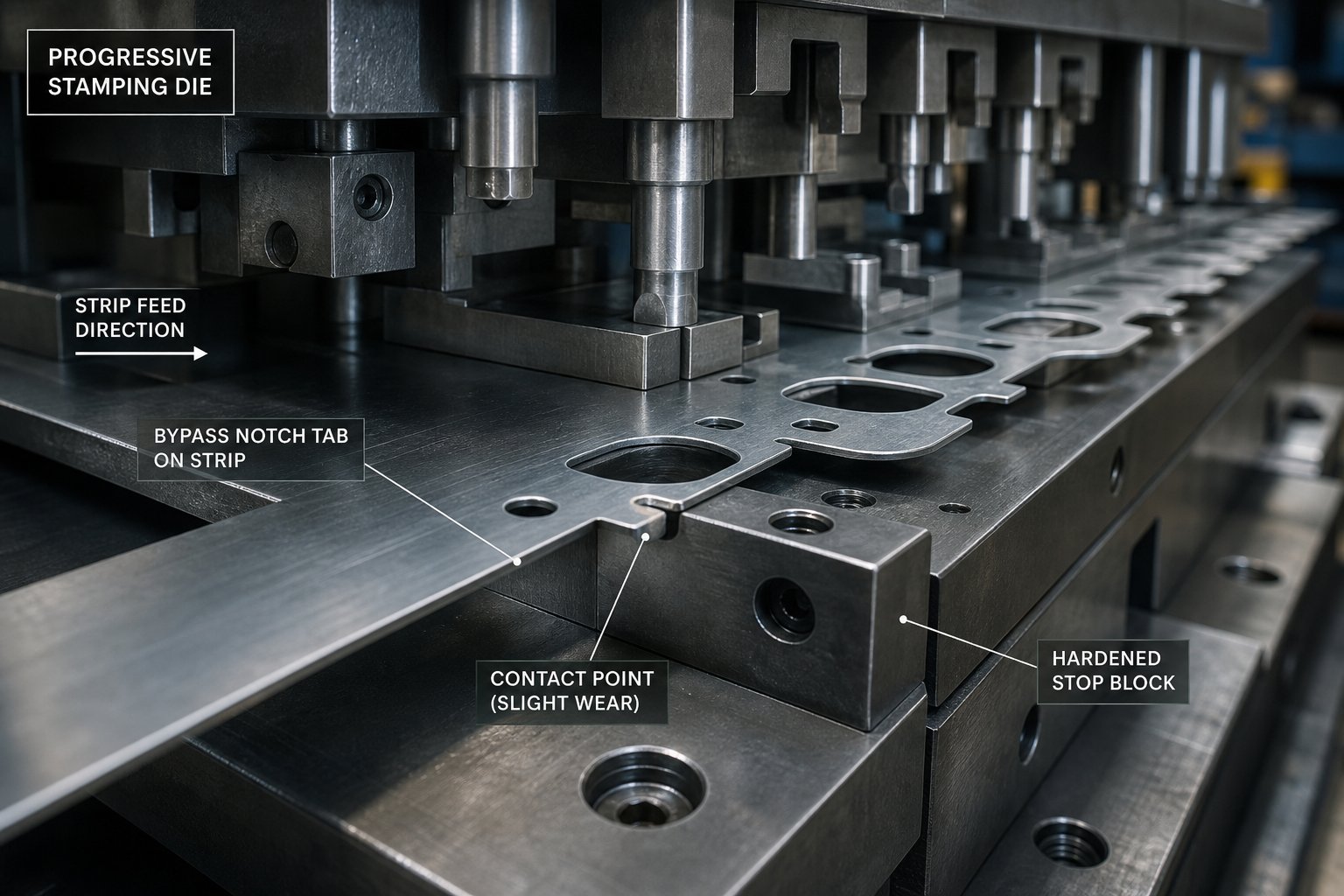
What Bypass Notches Do in Progressive Stamping Dies
Imagine a coil of sheet metal advancing through a progressive stamping die at hundreds of strokes per minute. Each station along that die performs a different operation - piercing, forming, trimming - and every one of those operations depends on the strip landing in exactly the right position. Even a few thousandths of an inch of over-travel or under-travel can produce scrap parts, elongated pilot holes, or outright die damage. This is where bypass notches earn their place in the metal forming process.
A bypass notch is a strip-control feature cut into (or left on) the edge of the coil strip, specifically designed to regulate how far the material advances between stations. These notches interact with hardened stops or tongues mounted in the lower die shoe, creating a mechanical limit on feed distance in the direction of strip travel. When the feeder pushes the strip forward, the notch feature contacts its mating component in the die, physically preventing over-feed before the press cycles. Two distinct configurations exist - positive and negative bypass notches - and each uses a different geometric relationship between the strip edge and the die-mounted stop to accomplish the same goal: reliable, repeatable strip progression.
Why Strip Control Matters in Progressive Dies
Uncontrolled strip movement is one of the fastest paths to costly press downtime. When a strip over-feeds, punches and forming stations engage material in the wrong location, producing dimensional errors and potentially crashing hardened tooling into itself. A single severe over-feed event can damage multiple stations simultaneously, as Art Hedrick notes in The Fabricator - one die crash from overfeeding can cost 100 times more than the material consumed by a properly designed notch.
Under-feed creates its own problems. Parts come out short, pilot holes no longer align with pilots, and the strip buckles between stations. Edge camber from the coil slitting process compounds these issues by making the strip drift laterally during feeding. Negative and positive bypass notches in sheet metal stamping dies address both failure modes by establishing a hard mechanical boundary that the feed system cannot exceed, regardless of electronic control settings or operator error.
How Bypass Notches Differ from Other Registration Methods
You'll often hear bypass notches discussed alongside pilot pins, but the two serve fundamentally different roles in the strip-control hierarchy. Pilots are precision-ground pins that enter pre-pierced holes in the strip after it has already been fed forward. Their job is fine registration - correcting the last few thousandths of positional error so that each station operates on target. Pilots typically have 0.0005 to 0.001 in. of clearance to their holes, as PMA technical guidance on piloting explains, and they engage only after the feed rolls release the strip.
Bypass notches operate upstream of that sequence. They set the coarse feed limit - the maximum distance the strip can travel - before the pilots ever touch the material. Think of notches as the guardrails and pilots as the lane-centering system. One prevents catastrophic deviation; the other fine-tunes position. Side guides and carrier-strip designs offer lateral constraint and vertical support, but neither provides the positive feed-distance control that a notch delivers. The purpose of bypass notches in stamping dies breaks down into three primary functions:
- Feed limit - physically preventing the strip from traveling beyond one pitch distance per stroke
- Strip stabilization - removing edge camber and providing a consistent reference surface along the strip edge
- Station-to-station registration backup - offering a secondary positioning reference that supplements pilot pins, especially during setup and first-hit conditions
With these roles defined, the critical question becomes which type of notch - positive or negative - best serves a given application. That distinction hinges on whether material remains on the strip as a protruding tab or gets removed to create a slot, and the terminology itself carries a surprising amount of confusion across the industry.
Resolving the Positive vs Negative Terminology Confusion
Ask five die designers what a "positive bypass notch" means, and you might get three different answers. This is not an exaggeration. The terminology around negative and positive bypass notches in sheet metal forming stamping dies has never been fully standardized, and the resulting confusion shows up in training sessions, die build specifications, and shop-floor conversations every day. Before diving deeper into geometry and function, it pays to untangle the naming problem so that everyone reading this article - and everyone on your team - speaks the same language.
The root of the issue is simple: the words "positive" and "negative" can logically describe the feature from two completely different reference points. One convention focuses on what happens to the strip edge. The other focuses on what happens inside the die cavity. Both make sense within their own logic, which is exactly why both persist.
Convention A vs Convention B Explained
Convention A - the strip-referenced definition - labels the notch based on what the strip edge looks like after the operation. If material protrudes from the strip edge as a tab or ear, that is called a "positive" notch because material has been added to the strip profile relative to the nominal edge line. If material has been removed from the strip edge creating a slot or recess, that is a "negative" notch because the strip profile is now below the nominal edge. This convention is intuitive when you hold the strip in your hand and look at its edge: bumps out are positive, cuts in are negative.
Convention B - the die-referenced definition - labels the notch based on whether the die performs a cutting action or a non-cutting action to create the feed-stop feature. Under this framework, cutting material away to produce a slug is sometimes called a "positive" notch operation because the die is actively doing something (positively engaging material). Leaving a tab intact by trimming around it may be called "negative" because the die is not cutting the tab itself - it simply emerges as a byproduct of adjacent blanking. Some shops further associate "positive stop" with any scenario where a solid mechanical stop blocks the strip, regardless of how the stop surface was created.
Why do both conventions survive? Shop-floor language evolves locally. A toolmaker trained at one facility carries that vocabulary to the next job. Training materials from organizations like PMA (Precision Metalforming Association) and the Tool and Manufacturing Association generally favor the strip-referenced definition - describing the distinction as material-on-strip versus material-removed-from-strip - but older textbooks and regional shop traditions sometimes use the die-referenced version. The result: bypass notches in sheet metal forming carry different labels depending on who built the tool and where they learned.
The Framework Used in This Article
To keep things clear from this point forward, this article adopts the strip-referenced convention, which aligns with PMA educational guidance and most modern progressive die design literature. Here is the framework:
- Positive bypass notch - material protrudes from the strip edge as a tab that contacts a hardened stop block in the die, preventing over-feed.
- Negative bypass notch - material is removed from the strip edge, creating a slot or recess that a die-mounted tongue or finger enters to arrest strip travel.
The bypass notches sheet metal forming purpose remains identical in both types: mechanically limiting feed distance. Only the geometric relationship between strip and die differs. The table below gives you a quick-reference tool to map whatever terminology your shop uses onto the definitions in this article.
| Term Used Here | Alternate Names | Defining Characteristic | Strip Edge Appearance |
|---|---|---|---|
| Positive bypass notch | Positive stop tab, ear stop, lance-and-form stop, French notch (tab type) | Strip material protrudes outward as a tab; tab contacts a hardened stop block mounted in the die | Tab or ear extends beyond the nominal strip edge |
| Negative bypass notch | Pitch notch (slug type), French notch (slot type), cutout stop, relief notch | Material is removed from the strip edge; a die-mounted tongue enters the resulting slot to stop feed | Slot or recess cut into the strip edge below the nominal profile |
If your shop calls the slug-producing version a "pitch notch" and the tab version a "lance stop," you can still follow along - just match your term to the defining characteristic column. Industry literature from The Fabricator commonly uses "pitch notch" to describe the slug-producing (negative) type, which reinforces the strip-referenced convention this article follows.
With terminology settled, the real engineering distinctions come into focus. Each notch type carries its own geometry, its own interaction sequence with the press feed system, and its own set of advantages on the shop floor. The positive variant starts with a question of tab shape - how much material stays on the strip, in what profile, and how it meets the stop block at full feed.
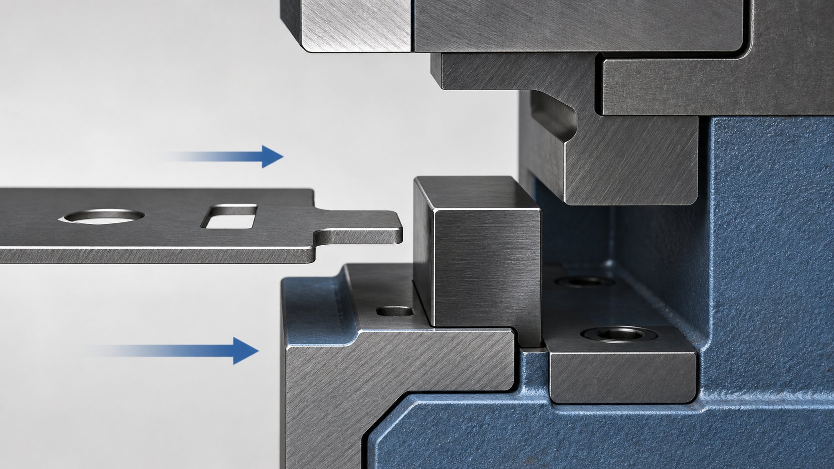
Positive Bypass Notch Geometry and Function
Picture the strip edge after it passes through an early trimming or blanking station. In a positive bypass notch configuration, not all of the edge material gets cut away. Instead, a small tab is intentionally left protruding outward from the strip profile. This tab travels forward with the strip on each feed cycle and eventually contacts a hardened stop block fixed in the lower die shoe, physically halting forward motion. No material is punched out, no slug drops into the die - the stop action is purely contact-based between the retained tab and an immovable block.
This makes the positive notch a mechanically elegant solution. The strip itself carries the stop feature, while the die simply provides the mating surface. The geometry of that tab, however, must be carefully controlled to deliver reliable feed arrest without compromising strip integrity or wasting material.
Tab Geometry and Orientation in the Strip Layout
The typical positive bypass tab takes a rectangular or trapezoidal shape, extending perpendicular to the feed direction from one or both edges of the strip. Width - measured parallel to the feed direction - usually ranges from 1.5 to 3 times the material thickness, depending on the yielding force the tab must withstand at feed contact. Depth - how far the tab protrudes beyond the nominal strip edge - is generally kept between 2 and 5 mm, enough to provide a solid contact surface against the stop block without creating excessive material waste.
Trapezoidal tabs are common because a slight draft angle (typically 3 to 5 degrees per side) eases the trimming operation that forms the tab. The trim punches cut the strip edge profile on either side of the tab, leaving it standing proud. This draft also reduces stress concentration at the tab root - important because the tab must absorb the kinetic energy of the advancing strip each cycle without cracking or deforming over thousands of hits.
Tab position along the strip corresponds directly to pitch distance. Each tab sits exactly one pitch length from the next, measured in the feed direction. This spacing ensures that after each feed cycle, a fresh tab arrives at the stop block location in the die. Any positional drift in the tab - caused by punch wear in the trimming station or material elongation during feeding - accumulates over multiple pitches and manifests as registration error downstream.
The yield strength of the strip material directly governs the minimum tab cross-section. A material with higher yield strength and yield point can support a smaller tab because it resists plastic deformation under the impact load of feed arrest. Conversely, soft materials with high elongation require wider, more robust tabs to avoid bending or mushrooming at the contact face. This structural relationship between tab geometry and material properties becomes a key sizing consideration when designing for different alloys.
How the Positive Notch Interacts with the Feed Mechanism
The feeding sequence unfolds in a precise mechanical choreography during each press stroke:
- The press ram rises and feed rolls advance the strip one pitch distance in the feed direction.
- The protruding tab contacts the hardened stop block mounted in the lower die shoe, arresting forward motion. The strip cannot over-travel.
- Feed rolls release the strip, leaving it positioned against the stop.
- The press ram descends. Pilot pins enter pre-pierced holes in the strip, correcting any residual positional error (typically within 0.001 in.) and locking the strip for final registration.
- Forming, piercing, or blanking operations execute at each station simultaneously.
- The ram retracts, pilots withdraw, and the next feed cycle begins.
Notice that the tab provides the coarse feed limit while pilots handle fine positioning. The two systems operate in sequence, not in competition. This layered approach is especially valuable at high press speeds where feeder overshoot becomes more probable.
A positive bypass notch limits maximum feed distance by physical contact between strip material and a die-mounted stop - the strip literally cannot go farther than the tab allows.
The stop block itself is typically made from hardened tool steel (58-62 HRC) or carbide in high-volume applications. It mounts in a pocket machined into the lower die shoe, positioned so the contact face sits exactly one pitch distance from the previous station's registration point. Shim adjustability behind the block allows fine-tuning of stop position during die tryout.
Advantages of the Positive Bypass Notch
- No slug management - because no material is punched out to create the stop feature, there are no small slugs to shed, retain, or worry about pulling back into the die.
- Visual feed verification - a quick glance at the strip edge tells the operator whether the tab is contacting the stop properly. Witness marks on the tab face confirm consistent contact.
- Simple maintenance - wear occurs primarily on the stop block contact face, which is easy to inspect, measure with a pin gauge, and replace or regrind when wear exceeds tolerance.
- Strip edge camber correction - the trimming operation that forms the tabs also removes edge camber from the incoming coil, improving strip feeding behavior as noted in progressive die design guidance from The Fabricator.
These characteristics make positive notches a strong choice for medium-to-wide strips where the protruding tab does not compromise lateral strip rigidity. But what happens when the strip is narrow, or when nesting requirements demand every millimeter of edge material? That scenario calls for a different geometric approach - one where material is removed rather than retained.
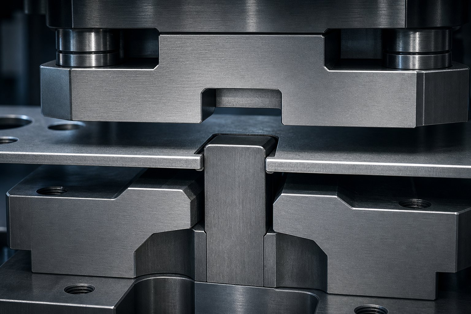
Negative Bypass Notch Geometry and Function
Instead of leaving material standing proud on the strip edge, the negative bypass notch takes the opposite approach: a dedicated punch removes a small section of material from the strip edge, creating a slot or recess. A hardened tongue or finger mounted in the die then enters that opening as the strip feeds forward, physically blocking further advancement. The strip stops not because something on it hits a wall, but because something in the die drops into a space that was cut into it.
This inversion of geometry changes almost everything about how the notch is designed, manufactured, and maintained - while achieving the same fundamental goal of feed-distance control in a progressive stamping die.
Slot Geometry and Die Tongue Configuration
The slot cut into the strip edge is typically rectangular, with a width (measured parallel to the feed direction) ranging from 3 to 6 mm for most sheet metal gauges. Depth - how far the slot extends inward from the strip edge - is usually 2 to 4 mm, enough for the die tongue to engage securely but not so deep that it weakens the strip's cross-section between stations. Corner radii at the base of the slot are kept as small as practical, often 0.2 to 0.5 mm, to provide a defined stop surface for the tongue while avoiding stress risers that could initiate cracks during progressive feeding cycles.
The die-mounted tongue that enters this slot is a precision component in its own right. It is typically machined from hardened tool steel (D2 or M2 at 58-62 HRC) and ground to final dimensions with tight surface finish requirements. The tongue width is sized narrower than the slot width by a controlled clearance - typically 0.05 to 0.15 mm per side - to allow the strip to feed past the tongue and then arrest cleanly when the slot aligns with the tongue position.
Engagement depth - how far the tongue enters the slot - determines how securely the strip is held against over-travel. Shallow engagement risks the strip riding over the tongue if feed forces are high or if the strip lifts slightly during feeding. A minimum engagement of 1.5 mm is common, with deeper engagement preferred for thicker materials or high-speed applications where strip momentum is greater.
Tongue mounting configurations fall into two categories. Fixed tongues are machined as an integral feature of the die block or bolted permanently into the lower die shoe. Guided tongues are spring-loaded or cam-actuated, retracting below the strip plane during the press stroke and extending into the slot during the feed phase. Guided designs add complexity but allow the tongue to withdraw completely during forming operations, preventing interference with strip lift or part ejection.
Burr Direction and Its Effect on Strip Registration
Here is where bypass notches and burr formation in stamping intersect in a way that positive notches largely avoid. Cutting the slot requires a punch-and-die operation that shears material away from the strip edge. That shearing action produces a burr - a thin ridge of displaced material along the cut edge - and its direction matters significantly for downstream performance.
In a standard punch-down configuration, the burr forms on the bottom face of the strip at the slot edges. This means the burr side faces the lower die shoe as the strip travels through subsequent stations. If the die tongue enters from below (the most common arrangement), the burr ridge can interfere with clean tongue engagement, causing the strip to hang up slightly or register inconsistently from stroke to stroke. Over thousands of cycles, burr buildup on the tongue face accelerates wear and introduces positional scatter.
Burr height depends on punch-to-die clearance and punch sharpness. Optimal clearance for the notch-cutting operation - generally 5 to 10% of material thickness per side for mild steel - keeps burr height manageable. As the notch punch wears, burr height increases progressively. Monitoring burr height at the notch edges serves as an early indicator that the notch punch needs regrinding.
Burr direction also affects pilot pin entry at downstream stations. If the burr at the notch edge creates a slight upward curl on the strip bottom, it can lift the strip locally near pilot holes, increasing the effective clearance that pilots must correct. For tight-tolerance parts, some designers orient the notch-cutting operation to place the burr on the top face of the strip (punch-up configuration), where it does not interfere with die-surface contact. This approach requires slug management from below - adding a slug chute in the upper die half - but improves strip tracking on the lower die surface.
Work hardening at the sheared edges of the slot also plays a role. The cut zone undergoes significant strain hardening during the shearing process, making the slot edges harder and more brittle than the surrounding parent material. Over repeated feed cycles, if the tongue contacts these hardened edges with any lateral force, micro-cracking can develop at the slot corners. This effect is more pronounced in materials with low ductility or those already partially work hardened from prior coil processing.
Feed Sequence for Negative Notches
The mechanical sequence differs from the positive notch in a subtle but important way:
- The press ram rises, and the die tongue extends into position (or remains fixed in the die block).
- Feed rolls advance the strip one pitch distance. The slot, cut in a previous station, travels forward until its trailing edge contacts the tongue.
- The tongue-to-slot engagement arrests strip travel. The strip cannot advance beyond this point.
- Feed rolls release. Pilot pins descend into locating holes for final fine registration.
- The press ram descends, performing all station operations simultaneously.
- On ram retraction, the tongue retracts (if guided) or the strip lifts clear of the fixed tongue, and the next feed cycle begins.
Contrast this with positive notches, where the strip's own tab hits a static block. With negative notches, the die provides the moving (or static protruding) element that enters the strip. This distinction affects maintenance patterns - tongue wear is distributed across a small contact area that endures both engagement forces and any lateral strip drift during feeding.
Advantages and Disadvantages of Negative Bypass Notches
Advantages
- Tighter material nesting - no tab protrudes beyond the strip edge, so adjacent rows or parts in material nesting software for length of material calculations can be packed closer together, reducing scrap.
- Better suited for narrow strips - on strips where width is limited, a protruding positive tab could compromise lateral rigidity or interfere with side guides. The negative slot stays within the strip profile.
- Edge camber removal - like positive notches, the cutting operation removes irregular edge material, straightening the strip edge for smoother feeding through downstream stations.
- Defined stop surface - the tongue-to-slot contact provides a consistent, repeatable stop geometry that is less affected by strip surface condition or thickness variation.
Disadvantages
- Slug management - the notch-cutting punch produces a small slug each stroke. These slugs must be reliably shed from the die to prevent slug stacking, die damage, or surface marking on parts. As The Fabricator notes, shedding a strip of material as small as two times the metal thickness can be problematic.
- Slug pulling risk - if punch-to-die clearance is insufficient or if vacuum forms between the punch face and slug, the slug can be pulled back up with the retracting punch and deposited on the strip surface. This is a common failure mode in high-speed progressive die operations.
- Burr interference - as discussed above, burr formation at the slot edges requires careful clearance management and introduces a wear-dependent variable into strip registration accuracy.
- Tongue wear and maintenance - the tongue endures repetitive impact loading every press cycle. Unlike a flat stop block that distributes contact over a broad face, the tongue concentrates forces on a relatively small profile, accelerating wear and requiring more frequent inspection.
These tradeoffs make negative bypass notches the preferred choice in applications where material utilization is critical or strip width is constrained, while positive notches win where slug-free operation and simple maintenance take priority. The decision between the two often comes down to strip geometry, press speed, and the specific material being run - but before either type can function reliably, the die-making process itself must deliver the precision that both notch geometries demand.
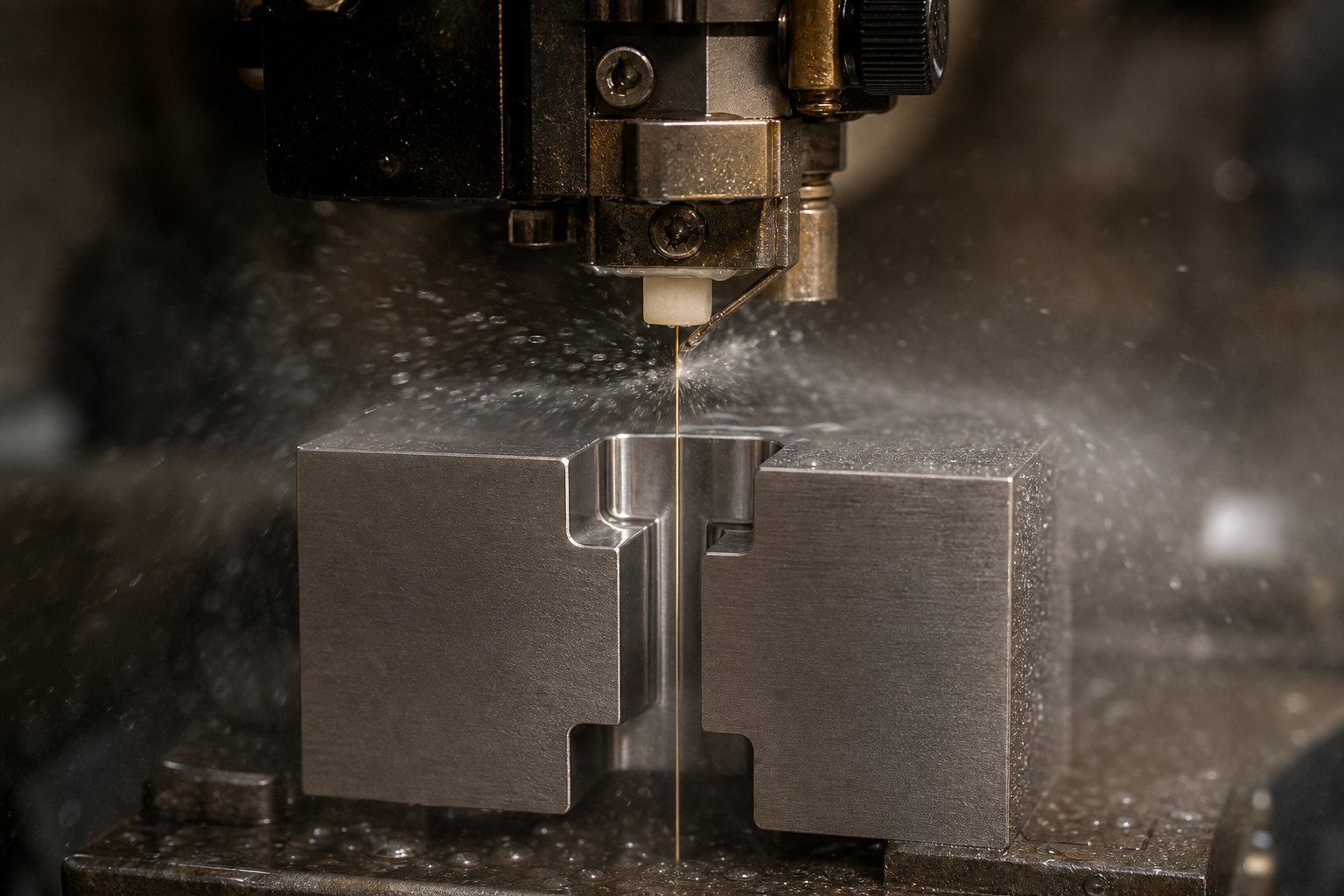
Die-Making Process for Bypass Notch Tooling
Precision in a bypass notch starts long before the first coil hits the press. It starts on the tool and die maker's bench - in the geometry of the punch profile, the accuracy of the die opening, and the clearance relationship between them. Whether you are building tooling for a positive tab or a negative slot, the die-making process determines how reliably that notch will perform over hundreds of thousands of press cycles. A poorly made notch punch wears fast, produces excessive burr, and turns a feed-control feature into a production headache.
Building these components demands tight tolerances, careful material selection, and machining methods capable of holding dimensions within tenths of a thousandth. Here is how experienced die makers approach it.
Cutting the Notch Profile with Wire EDM
For negative bypass notches, the punch must replicate the exact slot geometry that will be cut into the strip edge - typically a rectangular profile with controlled corner radii and straight sidewalls. The die opening must mirror that profile with precise clearance offsets applied per side. Achieving this level of accuracy by conventional grinding alone is difficult, especially when corner radii drop below 0.5 mm or when the punch cross-section is small enough that grinding wheel access becomes limited.
This is where EDM wire machining transformed the trade. Wire EDM uses a continuously fed thin wire electrode (typically 0.1 to 0.3 mm diameter brass or coated wire) to erode material along a programmed path, producing punch and die profiles directly from hardened tool steel blocks. The process offers several advantages specific to notch tooling:
- Post-heat-treatment machining - punches and die blocks can be fully hardened to 58-62 HRC before wire cutting, eliminating dimensional distortion from subsequent heat treatment. The die maker cuts the final profile in the hardened state.
- Tight corner radii - wire diameter dictates the minimum internal radius, so a 0.10 mm wire can produce corner radii as small as 0.05 mm on the die opening. This matters for notch slots where clean, defined stop surfaces are required.
- Exact clearance control - because wire EDM machines move in increments as fine as 0.001 mm (approximately 0.00004 in.), the die maker can program exact per-side clearance offsets into the die opening path. One block of tool steel can yield both the punch and the mating die section from the same cut, ensuring perfect geometric correspondence.
- One-piece die sections - rather than assembling multiple ground segments into a sectionalized die block (which risks segment movement under stamping loads), wire EDM produces the entire notch die opening from a single solid block. This is stronger, cheaper to produce, and more dimensionally stable over the life of the tool.
- Repeatable duplication - when a notch punch wears out, the original CNC program reproduces an identical replacement. No hand-fitting, no magnifier work, no guesswork. This dramatically reduces replacement lead time for a die maker maintaining production tooling.
The surface finish left by wire EDM (typically 0.8 to 1.6 micrometers Ra after a skim pass) also benefits notch performance. That fine texture retains lubricant on the punch sidewalls, reducing friction during material shearing and helping slugs shed cleanly from negative notch operations. Multiple skim cuts progressively improve surface quality when tighter finishes are needed for critical notch geometries.
Forming Positive Notch Tabs Through Edge Trimming
Positive bypass notch tabs require a different tooling approach. Rather than a dedicated punch cutting material away, the tab is formed by trimming around it. The strip edge trimming station - which removes the irregular mill edge from the incoming coil - is profiled so that its cutting geometry skips over the tab locations, leaving material standing proud at each pitch interval.
In practice, this means the trim punch and trim die carry a recessed or scalloped profile at each tab position. The wire EDM process is equally valuable here: the trim die opening must accurately reproduce the tab outline along with the straight-edge trim profile, all in one continuous cut path. Any mismatch between the trim die profile and the intended tab geometry results in tabs that are undersized (weak), oversized (wasting material), or mislocated (causing pitch errors).
Because the tab emerges as a byproduct of adjacent cutting rather than from its own dedicated punch, there is no separate slug generated at the tab location. This is one reason positive notches simplify slug management - the only slugs produced come from the straight-edge portions of the trim operation, and those are typically long continuous strips that shed reliably.
Clearance and Punch Design for Notch Operations
Clearance - the gap between the cutting punch and die opening, measured per side - is the single most consequential dimension in any notch-cutting operation. Too little clearance increases cutting force, accelerates punch wear, and can cause the slug to stick in the die opening. Too much clearance produces excessive burr, allows the slug to tilt during separation, and increases the risk of slug pulling on punch retraction.
The traditional "10% of material thickness" rule for per-side clearance applies well to low-carbon steel, but as MetalForming Magazine points out, relying on this single value for every material creates problems. Higher-strength steels fracture with less deformation, so they tolerate - and often benefit from - slightly larger clearances (12-15% per side) that reduce cutting force and punch shock. Aluminum and copper alloys, which deform more before fracturing, typically need tighter clearances (6-8% per side) to achieve clean shear and control burr height.
For notch punches specifically, the small cross-section of the punch (often only 3-6 mm wide) concentrates cutting forces on a limited area. This makes punch material selection critical:
- A2 tool steel - an air-hardening cold-work steel offering excellent toughness and dimensional stability after heat treatment. A2 resists chipping under the repetitive impact of notch cutting and is the preferred choice when shock loading is a concern - for example, when cutting notches in thicker gauges or higher-strength materials where snap-through forces are elevated. Typical hardness after tempering ranges from 57 to 62 HRC.
- D2 tool steel - a high-carbon, high-chromium steel with superior abrasive wear resistance due to abundant chromium carbides in its microstructure. D2 excels in long-run applications where the notch punch must maintain its edge profile over hundreds of thousands of cycles without regrinding. The tradeoff is lower toughness - D2 punches are more prone to chipping if subjected to lateral loading or misalignment.
The decision between A2 and D2 mirrors the broader tooling question: is the dominant failure mode wear or fracture? For most bypass notch applications running mild steel at moderate speeds, D2 delivers longer intervals between regrinds. For high-strength or thick materials where punch shock is the primary concern, A2's fracture resistance reduces catastrophic failures.
Maintenance: Wear Patterns and Regrind Intervals
Bypass notch tooling wears in predictable patterns. Knowing where to look - and what to measure - keeps notch performance consistent over the life of the die.
For negative notch punches, wear concentrates on the cutting edges, particularly at the corners where stress concentration is highest. As corners round off, burr height at the slot edges increases progressively. A die maintenance technician can track burr height with a simple dial indicator or optical comparator. When burr exceeds the allowable threshold (typically 10% of material thickness for most applications), the punch needs regrinding.
Regrinding a notch punch involves removing material from the punch face - the flat end that contacts the strip - to re-expose sharp cutting edges. Each regrind shortens the punch, so the punch holder or backing plate must be shimmed to maintain correct shut height. Wire EDM again proves valuable here: if edge wear is uneven or if corner geometry has degraded beyond what face grinding can correct, the punch can be re-profiled on a wire machine using the original program.
For positive notch tooling, wear occurs primarily on the stop block face where the strip tab impacts each cycle. This surface sees thousands of compressive impacts per hour. Hardened tool steel blocks (60+ HRC) withstand this well, but eventually the contact face develops a depression or witness mark that grows deeper over time. When this depression exceeds 0.05 mm, the effective stop position has shifted - meaning the strip now over-feeds slightly before contacting the worn surface. Measuring stop block face condition with a depth micrometer or surface plate comparison identifies when replacement or regrinding is needed.
Tongue components in negative notch systems wear on their engagement faces - the surfaces that contact the slot walls during strip arrest. Because the tongue is narrower than the slot by design, any wear on the tongue further increases this clearance, reducing positional accuracy. Tongue width should be periodically measured with a micrometer and compared against the nominal dimension.
For shops that need precision notch-cutting assemblies with tightly controlled clearance and geometry - especially for complex progressive die builds - sourcing from tooling suppliers who specialize in custom die components can reduce development time significantly. YICHEN's stamping die solutions, for example, provide custom-engineered punch and die assemblies designed for bypass notch accuracy, including clearance optimization and material-specific geometry tailored to the application. This kind of supplier partnership is particularly valuable when in-house wire EDM capacity is limited or when the die design calls for non-standard notch configurations that benefit from specialized tooling expertise.
With the manufacturing process delivering precise, well-clearanced notch tooling, the next engineering challenge shifts to dimensioning - how wide should the tab be, how deep should the slot go, and what proportional relationships govern these decisions across different materials and strip geometries?
Design Rules for Bypass Notch Sizing
How wide should the tab be? How deep should the slot go? These are not arbitrary decisions. Every dimension in a bypass notch ties back to three governing parameters: the thickness of the strip material, the width of the strip itself, and the pitch distance between stations. Get the proportions wrong and you end up with tabs that bend over under feed force, slots that let the strip slip past, or notch features so oversized they waste material and compromise strip rigidity. The sizing rules below give you a framework for getting it right the first time.
Before jumping into specific numbers, it helps to understand what is yield strength in practical terms for this application. Yield strength is the stress level at which a material begins to deform permanently - and it directly determines how much load a bypass notch tab or slot wall can absorb before it distorts. The yield strength of steel varies widely depending on grade, from roughly 200 MPa for deep-drawing low-carbon grades up to 1000+ MPa for advanced high-strength steels. That range creates a corresponding range in minimum notch dimensions.
Sizing Positive Bypass Notch Tabs
The tab must withstand the impact force of the advancing strip without bending, mushrooming, or fracturing at its root. That force depends on strip mass, feed velocity, and how abruptly the feeder decelerates - but for practical sizing, the critical variable is the yield stress of the tab material, because the tab is made from the strip itself.
A widely used starting point: tab width (measured parallel to the feed direction) should be at least 2 to 3 times the material thickness. For a 1.0 mm strip, that means a minimum tab width of 2.0 to 3.0 mm. Thinner materials or softer alloys push toward the higher multiplier because the reduced cross-section and lower yield point for steel in those grades cannot absorb feed forces over a narrow contact area without plastic deformation.
Tab depth - how far the tab protrudes beyond the nominal strip edge - typically ranges from 1.5 to 4 times the material thickness. Deeper tabs provide more contact area against the stop block but consume more material and can interfere with side guides if strip width is tight. The contact area (tab width multiplied by material thickness at the tab face) must exceed the minimum needed to keep compressive stress below the yielding point of steel used in the stop block - otherwise the block face itself wears prematurely.
For high-strength materials where the yield strength vs tensile strength ratio is high (above 0.85), tabs can be sized at the lower end of these ranges. The material resists deformation effectively even with a smaller cross-section. Conversely, soft aluminum or annealed copper with high elongation and low yield limit of steel equivalents require oversized tabs - often 4 times thickness or more - to prevent tab roll-over during aggressive feeding.
Sizing Negative Bypass Notch Slots
The slot cut into the strip edge must be wide enough for the die tongue to enter with controlled clearance, yet narrow enough to provide a precise stop. Slot width (parallel to feed direction) is sized relative to tongue width: typical per-side clearance between tongue and slot wall runs 0.05 to 0.15 mm. This means the slot is 0.10 to 0.30 mm wider than the tongue overall.
If the clearance is too tight, the strip may bind against the tongue and resist feeding. If the clearance is too loose, positional accuracy degrades - the strip can over-travel by the amount of the excess gap before the slot wall contacts the tongue. For applications demanding registration accuracy within 0.05 mm, the tongue-to-slot fit must be held to 0.05 mm per side or tighter.
Slot depth (perpendicular to the feed direction, measuring how far the slot extends inward from the strip edge) follows a depth-to-width ratio guideline. A depth-to-width ratio between 0.5:1 and 1.5:1 keeps the slot structurally sound while providing enough engagement surface for the tongue. Going deeper than 1.5 times the slot width weakens the strip cross-section and risks crack initiation at the slot base - particularly in materials with low yield strain steel characteristics or those already strain hardened from coil processing.
Tongue engagement depth - how far the tongue enters the slot - should be at least 1.5 mm or 1.5 times material thickness, whichever is greater. Deeper engagement adds security against strip lift during high-speed feeding but requires a correspondingly deeper slot, which removes more edge material.
Pitch Tolerance Stack-Up
Every notch feature is positioned relative to a datum established at the first station. As the strip progresses through 10, 20, or 30+ stations, any positional error in the notch compounds. If the notch punch is located 0.02 mm off nominal, that error accumulates at every pitch - by station 20, the strip has drifted 0.4 mm from ideal position. This stack-up is why notch station positional tolerances are typically held to within 0.01 mm during die construction, and why die makers verify notch position using coordinate measuring machines rather than surface-plate methods.
The table below summarizes the key proportional guidelines in a format you can reference during design reviews.
| Parameter | Positive Notch Guideline | Negative Notch Guideline | Governing Factor |
|---|---|---|---|
| Feature width (parallel to feed) | 2-3x material thickness minimum | Tongue width + 0.10 to 0.30 mm total clearance | Yield stress of strip material; required positional accuracy |
| Feature depth (perpendicular to feed) | 1.5-4x material thickness | Depth-to-width ratio of 0.5:1 to 1.5:1 | Strip edge rigidity; tongue engagement requirement |
| Tongue/stop engagement | Full tab face contacts stop block | Minimum 1.5 mm or 1.5x material thickness | Feed velocity; strip mass and momentum |
| Position tolerance | Within 0.01 mm of nominal pitch | Within 0.01 mm of nominal pitch | Number of stations; cumulative stack-up budget |
| Minimum tab/slot cross-section | Higher yield strength allows smaller tabs | Higher strength allows shallower slots | Material yield strength and elongation |
These guidelines provide a solid starting point, but remember that the elastic modulus and strain-hardening behavior of the specific alloy you are running will shift these numbers. A mild steel strip behaves very differently from a spring-temper stainless or a 6000-series aluminum at the same thickness. Those material-specific differences - and how they change the notch design conversation - deserve their own detailed examination.
Material-Specific Bypass Notch Considerations
A bypass notch sized perfectly for cold-rolled mild steel will not perform the same way in dual-phase 780 or aluminum 5052. The strip material changes everything - cutting forces, burr behavior, tab durability, tongue wear rate, and even the effective position of the notch after the press cycles. Designing notch geometry without accounting for the specific alloy running through the die is like tuning a feed system without knowing the strip thickness. The numbers might look right on paper, but the press tells a different story.
Two material properties sit at the center of this conversation. The elastic modulus - the stiffness of the material, governing how much it deflects under a given load before permanent deformation begins - determines how the strip behaves around the notch zone during feeding. Strain hardening and work hardening characteristics dictate how the material's strength evolves as it deforms, affecting both the cutting operation that creates the notch and the long-term structural integrity of the notch feature itself. Together, these properties create a unique design equation for each material family.
High-Strength Steel and Advanced High-Strength Steel
When you move from a 200 MPa mild steel to a dual-phase or TRIP steel with yield strengths above 500 MPa, the bypass notch conversation shifts in two simultaneous directions: higher forces to cut the notch, but a stronger tab once it is formed.
On the cutting side, advanced high-strength steels demand significantly more tonnage to shear. Research on AHSS forming behavior confirms that these materials require higher press loads, accelerated die wear mitigation through special die materials and surface treatments, and revised trim and cutting practices. For a negative bypass notch punch - already a small cross-section component absorbing concentrated forces - this translates directly to faster edge wear, higher shock loading per stroke, and a greater risk of corner chipping if the punch material lacks sufficient toughness. D2 tool steel, while excellent for wear resistance, may chip at the notch punch corners when cutting DP 980 or martensitic grades. Switching to a tougher substrate like A2 or even PM (powder metallurgy) grades with finer carbide distribution helps manage that fracture risk.
On the tab-strength side, the news is good. Because the elastic modulus of steel remains essentially constant across grades - approximately 200 GPa regardless of whether the steel is mild or ultra-high-strength - strip stiffness around the notch zone stays consistent. What changes is the yield strength. A higher yield point means a positive bypass notch tab can be physically smaller while still resisting deformation under feed-arrest impact. Where a mild steel tab might need to be 3 times material thickness wide, a DP 590 tab can safely run at 2 times thickness because the material simply will not yield under the same contact stress.
Springback introduces a less obvious complication. AHSS grades with yield-to-tensile ratios above 0.80 exhibit significant elastic recovery after trimming. When the trim punch cuts around a positive notch tab, the tab edges spring back slightly, changing the effective tab geometry. A tab designed to be perfectly rectangular may end up with a slight outward bow, shifting its contact point against the stop block. For critical applications, die designers compensate by adjusting the trim profile to account for this springback - essentially over-cutting slightly so the final relaxed tab shape matches the intended geometry.
- Notch cutting forces increase 40-80% compared to mild steel - size the press station accordingly
- Punch wear accelerates due to higher hardness and abrasive microstructure phases (martensite, bainite)
- Positive tabs can be downsized thanks to elevated yield strength - saves material, improves nesting
- Springback distorts tab geometry after trimming - compensate in the trim die profile
- Reduced elongation means less burr rollover but sharper fracture edges on negative notch slots
- Higher strain hardening capacity (especially in TRIP steels) increases edge hardness at the notch, improving long-term wear resistance of the slot walls
Aluminum and Soft Alloys
Aluminum flips the challenge. Cutting forces drop dramatically - the modulus of steel is roughly three times that of aluminum (200 GPa vs. approximately 70 GPa), which means aluminum strips are inherently less stiff and deflect more readily around the notch zone during feeding. A negative notch slot that stays perfectly open in steel may close slightly in aluminum as the strip flexes under its own weight or under side-guide pressure, making tongue engagement less reliable.
The bigger concern with aluminum, though, is galling. Research at Oakland University's Center of Advanced Manufacturing and Materials demonstrated that aluminum alloy AA5754 begins depositing material on die surfaces once contact pressure exceeds approximately 30-37 MPa - a threshold easily reached at the tongue-to-slot interface of a negative bypass notch. Every feed cycle presses the aluminum slot wall against the hardened tongue under deceleration forces. Over thousands of strokes, microscopic aluminum particles adhere to the tongue surface, building up a deposit that progressively reduces the effective tongue-to-slot clearance.
Once galling starts, it accelerates. The rough deposit surface increases friction, which increases contact pressure, which accelerates further material transfer. The result is a tongue that no longer fits cleanly into the slot, causing inconsistent strip arrest and positional scatter. Hard chrome plating on tongue surfaces helps - the Oakland University study found that hard-chromed D6510 cast iron inserts resisted galling onset to higher pressures than uncoated steel surfaces, partly due to lower surface roughness and a reduced coefficient of friction (0.045 vs. 0.08 for cast steel).
Burr behavior in aluminum also differs from steel. Because aluminum deforms extensively before fracturing, burrs tend to be longer and more ductile - folding over rather than breaking off cleanly. These rolled burrs can interfere with tongue engagement in negative notch systems and can build up on die surfaces over time. Tighter punch-to-die clearances (6-8% per side rather than the 10% common for steel) help control aluminum burr formation at notch edges.
- Low material modulus (approximately 70 GPa) reduces strip stiffness - slots may close under lateral pressure
- Galling on die tongues is the dominant failure mode - use hard chrome or PVD-coated tongue surfaces
- Ductile, folding burrs require tighter clearances (6-8% per side) to control
- Positive notch tabs require larger cross-sections (3-4x material thickness) due to low yield strength
- Lubrication at the notch zone is critical - dry or under-lubricated conditions accelerate galling onset
- Softer material means stop block wear is minimal, but strip tab mushrooming becomes the concern
Copper Alloys and Work-Hardening Materials
Copper and its alloys - brass, phosphor bronze, beryllium copper - bring a unique variable into the bypass notch equation: progressive strain hardening and work hardening during feed advancement through the die. Each forming station the strip passes through imparts some degree of plastic deformation to the carrier material. By the time the strip reaches downstream stations, the material adjacent to the notch features has work hardened significantly compared to its initial annealed or half-hard condition.
This matters because the notch was designed based on the incoming material properties - but by station 15 or 20, the strip near the notch edges may be 30-50% harder than it was at station 1. For positive notch tabs, this is generally beneficial: the tab becomes more resistant to deformation as it hardens, meaning it performs better as a stop feature in later stations than it did in earlier ones. But for negative notch slots, the hardened slot edges become more brittle. Micro-cracking at slot corners - rare in the first few thousand hits - can develop as the cumulative deformation from repeated tongue engagement meets material that has lost its ductility through work hardening.
The elastic modulus of copper alloys (110-130 GPa) sits between aluminum and steel, providing moderate strip stiffness. Notch dimensions can generally follow steel guidelines scaled slightly upward to account for the lower stiffness and typically lower yield strength of annealed copper. However, for spring-temper or work-hardened copper strips, the effective yield strength at the notch zone can approach that of mild steel, allowing similar proportional sizing.
- Progressive work hardening changes material properties station-to-station - design for the hardened condition
- Positive tabs benefit from hardening (become stronger over die life)
- Negative slot corners risk micro-cracking as ductility decreases with accumulated strain
- Moderate elastic modulus (110-130 GPa) - intermediate stiffness between aluminum and steel
- Galling risk is lower than aluminum but higher than steel - monitor tongue surfaces in phosphor bronze applications
- Generous corner radii on negative notch slots (minimum 0.3 mm) help prevent stress-concentration cracking
Pre-Coated and Surface-Treated Materials
Galvanized steel, pre-painted stock, tin-plated material, and organic-coated strips all pass through progressive dies with bypass notch systems - and they all present the same fundamental problem: the coating at the notch edge gets damaged during the cutting or trimming operation, and debris from that damaged coating migrates into the die.
When a notch punch shears through galvanized steel, it does not just cut the base metal. It also fractures and displaces the zinc coating along the sheared edges. Zinc particles flake off, accumulate on punch faces and die tongues, and pack into clearance gaps. Over thousands of strokes, this zinc buildup effectively reduces the designed clearance between tongue and slot (in negative notch systems) or between tab and stop block (in positive systems). The result is binding, inconsistent strip arrest, or - in severe cases - the strip jamming against a zinc-packed tongue and tearing the notch feature entirely.
For positive notch tabs, coating damage at the tab edges exposes bare metal that corrodes quickly in humid shop environments if the stamped strip sits in a storage rack between operations. This cosmetic issue may or may not matter depending on the final application, but it is worth noting for parts with visible edges.
Pre-painted or organic-coated materials present a similar debris challenge. The coating chips off in thin flakes during shearing and accumulates on die surfaces. Because organic coatings are softer and more compliant than zinc, they tend to smear rather than flake, creating a gummy buildup that increases friction and attracts additional debris. Regular die cleaning cycles - more frequent than for bare steel - are essential to maintain notch function in pre-coated material applications.
- Zinc or coating debris reduces effective clearances over time - schedule frequent cleaning intervals
- Coating fracture at shear edges creates loose particles that pack into tongue-slot gaps
- Positive notch tabs expose bare substrate at trimmed edges - potential corrosion concern
- Die tongue surfaces may need PVD or DLC coatings to resist adhesion buildup from soft coatings
- Punch-to-die clearance should be slightly increased (1-2% per side above bare-metal specification) to accommodate coating thickness
- Vacuum or air-blow systems at the notch station help evacuate coating debris before it accumulates
Each material family reshapes the bypass notch design conversation in specific, predictable ways. The underlying physics - elastic modulus metals behave according to, strain-hardening rates, fracture characteristics - drive those differences. Knowing your material before sizing your notch is not optional; it is the difference between a feature that runs maintenance-free for 500,000 hits and one that starts causing feed problems at 50,000. But even perfectly designed and material-matched notches eventually wear, shift, or degrade - and when they do, the symptoms show up as part defects and press stoppages that demand systematic diagnosis.
Troubleshooting Bypass Notch Failures in Production
A bypass notch system that ran flawlessly for 200,000 strokes does not fail all at once. It degrades - gradually, measurably, and with symptoms that point directly to the root cause if you know what to look for. The challenge on a production floor is connecting what you see (short feeds, dimensional scatter, buckled carriers) to what is actually happening inside the die at the notch station. This section gives you a structured failure-mode reference you can use at the press to diagnose, confirm, and correct bypass notch problems before they cascade into part rejections or die damage.
Most bypass notch failures share a common pattern: something that once stopped the strip reliably no longer does so consistently. The strip either travels too far, not far enough, or arrives in the correct position but with enough scatter to push part dimensions out of tolerance. The difference between a quick fix and hours of downtime often comes down to recognizing which failure mode you are dealing with - and whether it affects the positive notch system, the negative notch system, or both.
Positive Notch Failure Modes and Corrections
Positive bypass notches fail in ways that are often visible on the strip itself. Because the tab is physically present on the strip edge, you can inspect it directly - looking for deformation, witness marks, and wear patterns that tell you exactly where the system is breaking down.
Tab bending or roll-over. When the tab bends in the feed direction rather than stopping the strip cleanly, you will see intermittent over-feed at the notch station. Parts downstream show dimensional shift in the feed direction - holes drift forward, blanked edges are uneven, and trim scrap lengths become inconsistent. The root cause is usually an undersized tab that cannot absorb feed-arrest forces without yielding. This happens when the strip material has lower yield strength yield stress values than assumed during design, or when a material change (even within the same grade specification) introduces softer coils. Materials that have undergone repeated processing - already partially work hardened from slitting or leveling - may behave differently from fresh annealed stock at the tab root.
The fix: verify tab dimensions against the design specification. If the tab geometry matches the print but still bends, the tab cross-section is insufficient for the actual material properties and feed forces involved. Widen the tab by modifying the trim die profile, or reduce feed velocity to lower the deceleration impact on the tab face. In some cases, the stop block position has shifted forward (from shim settling or bolt relaxation), meaning the tab contacts the block at an angle rather than flat - re-shimming the stop block to restore perpendicular contact resolves this.
Stop block face wear. Every press cycle drives the tab into the stop block face under compressive load. Over millions of hits, a depression forms at the contact zone - effectively moving the stop surface deeper into the die shoe. The symptom is a gradual, progressive over-feed that worsens linearly with stroke count. Parts show slowly drifting dimensions in one direction, and the drift does not reset between die sharpening cycles because sharpening addresses cutting edges, not stop block faces. As progressive die failure analysis confirms, wear in one zone often creates cascading effects across multiple stations simultaneously.
The fix: measure the stop block contact face with a depth micrometer or surface plate comparison. If the depression exceeds 0.05 mm, replace or regrind the block. For high-volume dies, upgrading to a carbide stop block face (brazed insert or solid carbide) extends the replacement interval dramatically - carbide resists compressive wear far better than tool steel at the same hardness.
Tab fracture. A tab that breaks off entirely is a more severe version of the bending problem, and it leaves no stop feature at all for that pitch interval. The press cycles normally, but one station gets a full double-feed because the broken tab cannot arrest the strip. Symptoms include periodic (not every-stroke) severe misfeed events that produce scrap parts at regular intervals corresponding to the missing tab position in the coil. The cause is often material fatigue - the tab root experiences cyclic loading (compression on impact, tension on strip lift) that eventually initiates a crack, especially in materials that have been deformation hardened through prior coil processing or in-die forming.
The fix: increase the corner radius at the tab root to reduce stress concentration. If the material is inherently brittle or has been excessively work hardened by upstream operations, redesign the tab with a wider root section or switch to a trapezoidal profile that distributes stress more evenly. Check also for lateral strip drift that could be loading the tab in bending rather than pure compression.
Negative Notch Failure Modes and Corrections
Negative bypass notch failures tend to be less visible on the strip surface but more disruptive to production because they often involve slug management problems that can damage the die.
Tongue wear and clearance growth. The die tongue that enters the slot wears on its engagement faces - the surfaces that contact the slot walls during strip arrest. As the tongue narrows from repeated impact, the effective clearance between tongue and slot grows. The strip can now over-travel by the amount of that additional clearance before the slot wall contacts the worn tongue face. Symptoms mirror stop block wear in positive systems: gradual dimensional drift in the feed direction, but specifically worsening at a rate proportional to tongue wear rate rather than stroke count alone.
The fix: measure tongue width with a micrometer at regular intervals (every 50,000-100,000 strokes for standard tool steel tongues). When width falls below the minimum specification, replace the tongue. For dies running abrasive materials or high-strength steel, consider upgrading to carbide-tipped tongues or applying PVD coatings to reduce surface wear rate.
Slug pulling from notch operations. This is arguably the most dangerous negative notch failure mode. When the slug cut from the strip edge adheres to the punch face during retraction and gets carried back into the die, it can land on the strip surface and get stamped into subsequent parts - or worse, wedge between die components and cause a crash. The Fabricator identifies several contributing factors: vacuum between the punch face and slug, large cutting clearances that prevent slug compression into the die opening, and magnetized punches that attract ferrous slugs after surface grinding. For notch operations specifically, the small slug size (often only 3-6 mm wide) makes vacuum effects proportionally stronger relative to slug weight.
The fix: add a vacuum-relief vent hole through the center of the notch punch to break the air seal during retraction. If the punch cross-section is too small for venting, install a positive ejector (spring pin) in the punch face that pushes the slug off during withdrawal. Verify that the die button has adequate slug retention - a slight reverse taper (0.0005 to 0.001 in. per side, as recommended in die science literature) compresses the slug into the matrix and prevents it from backing out. Demagnetize all notch punches and die components after any grinding operation.
Burr buildup and strip tracking interference. As the notch punch wears, burr height at the slot edges increases. That growing burr ridge can interfere with tongue entry, cause the strip to ride up on one side, or prevent the slot from seating fully against the tongue contact face. The symptom is inconsistent strip arrest - some strokes register normally while others show slight over-travel or angular skew in the strip. Part dimensions may show random scatter rather than the linear drift characteristic of wear-based problems.
The fix: inspect burr height at the notch edges with a dial indicator or optical comparator. If burr exceeds 10% of material thickness, regrind the notch punch to restore sharp cutting edges. Also verify that punch-to-die clearance has not drifted due to component wear or shifting - clearance that was correct at installation may have changed if the die block or punch retainer has moved. Incorrect clearance is a primary driver of excessive burr formation, as industry troubleshooting references confirm.
Slot enlargement from repeated impact. The trailing wall of the slot - the surface that actually arrests strip travel by contacting the tongue - absorbs impact load every cycle. Over time, this wall can deform slightly in the feed direction, effectively widening the slot. Unlike tongue wear (which narrows the tongue), slot enlargement increases the gap from the strip side. Both cause the same symptom: progressive over-feed. Distinguishing between the two requires measuring both the tongue width and the slot width independently.
The fix: if slot walls have deformed beyond tolerance, the only correction is to re-cut the notch feature. This means the upstream notch-cutting punch must produce a slightly different slot position to compensate - or the tongue position must be adjusted downstream to match the enlarged slot. Prevention is better than correction here: ensure the material at the slot edges has not been excessively work hardened (which makes it brittle) or softened (which makes it yield under impact).
Quick-Reference Troubleshooting Matrix
The table below consolidates the most common bypass notch failure modes into a format a die maintenance technician can reference at the press. Print it, laminate it, and keep it at the tool bench.
| Symptom | Probable Cause | Notch Type Affected | Corrective Action |
|---|---|---|---|
| Gradual dimensional drift in feed direction | Stop block face depression or tongue width loss | Positive / Negative | Measure stop block depth or tongue width; replace or regrind when out of spec |
| Intermittent severe over-feed (periodic) | Tab fracture at root - missing stop feature at one pitch position | Positive | Increase tab root radius; widen tab cross-section; check for lateral loading |
| Tab visibly bent or mushroomed | Undersized tab or material yield strength lower than design assumption | Positive | Enlarge tab width in trim die; reduce feed speed; verify material cert |
| Random positional scatter (non-linear) | Burr buildup at slot edges interfering with tongue engagement | Negative | Regrind notch punch; verify clearance; check for punch misalignment |
| Slug marks or debris on part surfaces | Slug pulling - notch slug adhering to punch during retraction | Negative | Add punch vent hole or ejector pin; verify die button retention; demagnetize |
| Strip buckling between stations | Notch position error accumulating over multiple pitches | Both | Verify notch station positional accuracy on CMM; rework if drift exceeds 0.02 mm |
| Strip jamming during feed | Coating debris or zinc buildup packing tongue-to-slot clearance | Negative | Clean tongue and die pocket; increase cleaning frequency; add air blow |
| Inconsistent part dimensions at multiple stations | Combined notch wear plus pilot hole elongation from repeated misfeed | Both | Address notch root cause first; then evaluate pilot hole condition and pilot pin wear |
One pattern runs through every row in that table: bypass notch failures are progressive, not sudden. The first few thousand defective parts are often borderline - just barely out of tolerance, just barely showing drift. By the time an operator notices a clear problem, the wear or deformation that caused it has been developing for tens of thousands of strokes. This is why stroke-count-based inspection schedules - measuring stop block depression, tongue width, burr height, and tab condition at defined intervals - catch problems while they are still correctable with a quick regrind or shim adjustment rather than an emergency die pull.
Effective troubleshooting also means understanding where the bypass notch system fits within the broader strip-control ecosystem. A misfeed that looks like a notch failure might actually originate from pilot wear, feeder overshoot, or side-guide binding. Separating notch-specific failure modes from other registration problems requires comparing the notch system against alternative strip control methods - and knowing when each approach is doing its job versus when it needs backup.
Comparing Strip Control Methods and Choosing the Right Notch
Bypass notches do not operate in isolation. They sit within a layered system of strip control methods - each addressing a different piece of the positioning puzzle. Pilot pins handle fine registration. Side guides prevent lateral drift. Carrier strip geometry maintains structural integrity during feed. In-die sensors monitor what the mechanical systems are doing and flag deviations. The question for any progressive die designer is not which method to use, but which combination delivers the reliability the application demands.
Getting that combination wrong is expensive. A die that relies solely on pilots for registration in a high-speed application invites over-feed events that no amount of electronic protection can fully prevent. A die with bypass notches but no pilot pins lacks the final positional accuracy that tight-tolerance parts demand. Understanding how negative and positive bypass notches in a sheet metal stamping die relate to these other methods - and when each approach earns its place in the tool - separates robust die designs from those that require constant intervention on the press floor.
Bypass Notches vs Pilot-Only Registration
Imagine a 30-station progressive die running at 400 strokes per minute with a 50 mm pitch. At that speed, the feed rolls accelerate and decelerate the strip in milliseconds. Even a modern servo feed holding +/-0.01 mm accuracy under ideal conditions can overshoot when the strip's inertia overcomes roll friction - particularly with thick or wide material where strip mass is high. Feeder overshoot is not a defect in the equipment; it is physics.
Pilot pins can correct small positional errors - typically up to 0.5 mm depending on pilot diameter and strip hole clearance - but they cannot absorb a full overshoot event where the strip advances 2 or 3 mm beyond its intended position. When the pilot enters a hole that has drifted beyond correction range, it either forces the strip (shearing the pilot hole edges and creating progressive damage) or misses entirely, allowing the die to cycle on mislocated material. One severe over-feed can damage multiple stations simultaneously, as Art Hedrick emphasizes in his progressive die design guidance - and most die damage occurs in the first 10 hits during setup, when operator attention and electronic protection are at their weakest.
Bypass notches eliminate this vulnerability by providing a hard mechanical limit on feed distance that the strip physically cannot exceed. They function as the guardrail that keeps the strip in pilot-correctable range. In applications where any of the following conditions exist, relying on pilots alone introduces unacceptable risk:
- High press speeds (above 200 SPM) - strip momentum at feed deceleration increases proportionally with speed, making overshoot more probable
- Long-progression dies (20+ stations) - positional error accumulates over many pitches, and a single misfeed event damages many components simultaneously
- Thin materials (below 0.5 mm) - low strip mass means less inertial resistance to overshoot, and thin pilots are fragile
- Wide strips or heavy gauges - high strip mass stores kinetic energy that feed rolls may not fully arrest
- First-hit and setup conditions - the leading edge of the coil has no pilot holes yet, making the first several strokes entirely dependent on feed accuracy or mechanical stops
The complementary relationship between bypass notches and pilots is sequential, not redundant. Notches set the coarse limit - the maximum distance the strip can travel. Pilots then refine position within that window, correcting the last few thousandths of positional error so each station operates precisely on target. Removing either layer degrades the system. Removing the notch removes the safety net. Removing the pilot removes the precision.
Where Other Methods Fit
Side guides - hardened rails running along the strip edges inside the die - prevent lateral drift but do nothing to control feed distance in the strip-travel direction. They keep the strip tracking straight but cannot stop it from advancing too far. Carrier strip design (the connecting material between part features) provides structural continuity so the strip does not buckle, twist, or sag between stations, but again offers no feed-distance control. Both are essential for overall strip stability, and both work alongside bypass notches rather than replacing them.
Electronic feed-verification sensors - particularly the inductive proximity sensor type - monitor whether the strip has advanced correctly after each feed cycle. A sensor positioned to detect the presence (or absence) of a notch feature at the expected location sends a go/no-go signal to the press controller. If the strip is out of position, the press stops before cycling. This is valuable protection, but it is detection after the fact - it tells you something went wrong, not prevents it from going wrong. The mechanical notch provides the prevention; the inductive proximity sensor provides the verification layer on top of it.
Some shops attempt to substitute sensors for mechanical stops entirely, reasoning that electronic detection is faster and less tooling-intensive. The reality, as Hedrick notes, is less reassuring: die protection systems are frequently not set up properly, overridden during setup, or simply never connected to the press. A mechanical stop works regardless of whether someone remembered to plug in the sensor cable. The most robust systems use both - mechanical notches for physical prevention and sensors for electronic verification and press-stop logic.
Strip Control Method Comparison
| Strip Control Method | Best For | Limitations | Works With Bypass Notches |
|---|---|---|---|
| Positive bypass notch | Medium-to-wide strips; applications needing slug-free operation; dies where visual feed verification is valued | Consumes edge material (tab protrusion); tabs can bend in soft materials; not ideal for narrow strips | Serves as the primary coarse feed-limit system; pairs with pilots for fine registration |
| Negative bypass notch | Narrow strips; tight-nesting layouts; applications where edge material must stay within strip profile | Requires slug management; tongue wear demands more frequent inspection; burr can affect tracking | Serves as the primary coarse feed-limit system; pairs with pilots for fine registration |
| Pilot pins only | Low-speed presses; short-progression dies; skilled operators with consistent feeder performance | Cannot prevent gross over-feed; relies entirely on feed accuracy to stay within correction range; no first-hit protection | Yes - pilots provide the fine-registration layer that completes the notch system |
| Side guides | Lateral strip control; preventing edge drift and angular skew during feeding | No feed-direction control; cannot prevent over-travel or under-travel | Yes - guides constrain lateral position while notches constrain longitudinal position |
| Carrier strip design | Maintaining strip rigidity through forming stations; preventing twist and sag | Structural only; no active feed-distance control; width depends on part geometry constraints | Yes - a stiff carrier ensures the notch feature arrives at the stop in a flat, predictable orientation |
| In-die sensors (inductive proximity, optical) | Electronic verification of feed position; press-stop logic for misfeed detection; data logging for SPC | Detection only - cannot physically prevent over-feed; depends on setup, wiring, and operator compliance | Yes - sensors verify that the mechanical notch system is functioning correctly each stroke |
Choosing Positive or Negative for Your Application
With the broader strip-control ecosystem understood, the final design decision narrows to which notch type - positive or negative - fits the specific job. The answer depends on a handful of application-specific factors that interact with each other. Here is a practical decision framework:
Choose positive bypass notches when:
- Strip width is generous enough that a protruding tab does not compromise lateral rigidity or interfere with side guides
- The application benefits from slug-free operation - for example, dies where small slug management has historically caused problems
- Visual feed verification at the press is important for operator confidence during setup and production
- The strip material has moderate-to-high yield strength, allowing compact tab dimensions that do not waste excessive edge material
- Die maintenance resources favor simple stop-block replacement over tongue inspection and measurement
Choose negative bypass notches when:
- Strip width is narrow and a protruding tab would weaken the strip cross-section or conflict with side-guide clearance
- Material nesting efficiency is critical - the slot stays within the strip profile, allowing tighter row-to-row spacing
- The die already has reliable slug management infrastructure (vacuum systems, slug chutes, air blow-off) for other operations
- The strip material is soft or low-strength (aluminum, annealed copper) where positive tabs risk bending - a tongue-in-slot arrangement distributes arrest forces more favorably in these cases
- High-speed applications where strip lift between stations is substantial - guided (retractable) tongues can clear the strip path during forming operations
In many long-progression dies, both types appear in the same tool. A positive notch at the first station provides the first-hit solid stop for coil threading, while negative notches at downstream stations handle feed control where tighter nesting or strip-width constraints dictate. This hybrid approach leverages the strengths of each type exactly where they are needed most.
Implementing the right bypass notch strategy - whether positive, negative, or a combination - often requires close collaboration between the die designer who defines the strip layout and the tool and die builder who translates that layout into precision tooling. The notch type decision cascades into punch geometry, clearance specification, tongue design, stop block material, and maintenance scheduling. Getting all of those details right simultaneously is where a capable die-building partner makes the difference. YICHEN, for example, works with engineers through exactly these design-heavy decisions - from notch type selection and clearance optimization to material flow management across the full strip progression - providing custom stamping die solutions that align the notch system with the application's specific demands.
Strip control is never a single-feature problem. It is a system - mechanical stops, precision pilots, lateral guides, structural carriers, and electronic verification all working in concert. Bypass notches anchor that system by providing the one thing no other method can: a physical, unconditional limit on how far the strip travels each stroke. Whether that limit takes the form of a tab hitting a block or a tongue entering a slot, the result is the same - reliable progression, protected tooling, and consistent parts from first hit to last.
Frequently Asked Questions About Bypass Notches in Stamping Dies
1. What is the difference between a positive and negative bypass notch in a stamping die?
A positive bypass notch leaves a tab of material protruding from the strip edge that contacts a hardened stop block in the die to prevent over-feed. A negative bypass notch removes material from the strip edge, creating a slot that a die-mounted tongue enters to arrest strip travel. Both achieve the same goal of limiting feed distance, but they differ in geometry, slug management requirements, and suitability for different strip widths and materials. Positive notches avoid slug issues entirely, while negative notches allow tighter material nesting since no tab extends beyond the strip profile.
2. Why are bypass notches used instead of relying solely on pilot pins for strip registration?
Pilot pins provide fine registration by correcting small positional errors (typically up to 0.5 mm), but they cannot prevent gross over-feed events caused by strip momentum at high press speeds. Bypass notches establish a hard mechanical limit on feed distance that the strip physically cannot exceed, keeping it within the correction range of the pilots. At speeds above 200 SPM, in long-progression dies with 20+ stations, or during first-hit setup conditions where no pilot holes exist yet, bypass notches serve as the essential safety net that prevents die crashes and multi-station damage.
3. How do you size a bypass notch for different strip materials?
Notch sizing depends on material thickness, strip width, pitch distance, and the material's yield strength. For positive notch tabs, width should be 2-3 times material thickness for steel, increasing to 3-4 times for softer materials like aluminum. High-strength steels allow smaller tabs because their elevated yield strength resists deformation under feed-arrest impact. For negative notch slots, width is determined by tongue width plus 0.10-0.30 mm total clearance, with a depth-to-width ratio between 0.5:1 and 1.5:1. The elastic modulus and strain-hardening behavior of each alloy further adjust these proportions.
4. What causes slug pulling in negative bypass notch operations and how do you fix it?
Slug pulling occurs when the small slug cut from the strip edge adheres to the punch face during retraction due to vacuum, insufficient cutting clearance, or magnetized punch surfaces. The slug gets carried back into the die and can damage parts or tooling. Effective fixes include drilling a vacuum-relief vent hole through the notch punch, installing a spring-loaded ejector pin in the punch face, applying a slight reverse taper (0.0005-0.001 in. per side) in the die button for slug retention, and demagnetizing all notch punches after grinding. Maintaining correct punch-to-die clearance is also critical for prevention.
5. When should you choose a positive bypass notch over a negative one in die design?
Choose positive bypass notches when strip width allows a protruding tab without compromising rigidity, when slug-free operation simplifies maintenance, and when visual feed verification matters during setup. They work best with moderate-to-high yield strength materials that support compact tab dimensions. Choose negative notches for narrow strips where tabs would weaken the cross-section, when material nesting efficiency is critical, or for soft materials like aluminum where tabs risk bending. Many long-progression dies use both types - a positive notch at the first station for coil threading and negative notches downstream where nesting constraints apply.


