


What Is Progressive Die Metal Stamping
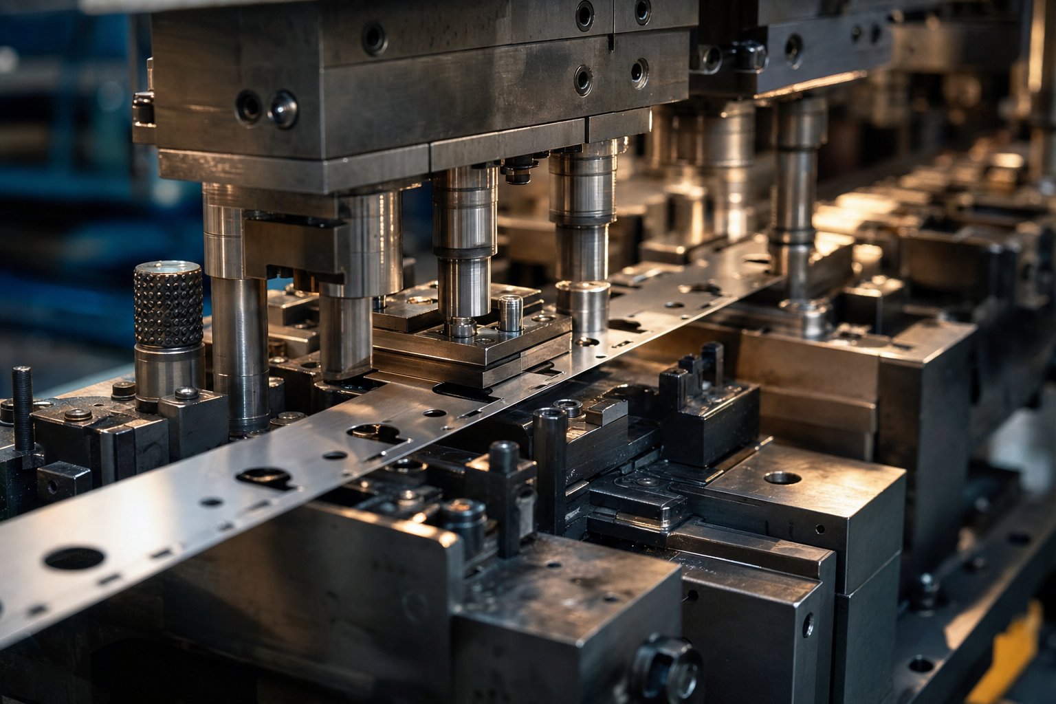
So what is a progressive die, exactly? Picture a single tool fitted with multiple stations arranged in sequence. A continuous metal strip feeds through those stations one pitch length at a time, and with every press stroke, each station performs a different operation - piercing, bending, forming, or cutting - on a different section of the strip simultaneously. By the time the strip exits the final station, a finished part drops out. That's progressive die metal stamping in its simplest form.
Progressive die stamping is a high-volume metal forming process in which a continuous strip of metal advances through a multi-station die, with each station performing a sequential operation, producing a completed part with every stroke of the press.
Why Progressive Stamping Exists
Imagine you need a complex metal bracket with holes, bends, and a drawn recess. In single-operation stamping, you'd run the part through separate dies, reposition it between each step, and absorb all the handling time and alignment risk that comes with it. Progressive stamping eliminates that problem entirely. One die, one press, one continuous feed - and you're producing complex finished parts at speeds that can reach 300 strokes per minute on high-speed equipment. No manual repositioning, no multi-setup bottlenecks, no part-to-part variation introduced by operators.
Who Uses Progressive Die Stamping Services
Three distinct groups typically source progressive die metal stamping services, and each arrives with different priorities:
- Production engineers focus on process capability, tolerances, and whether the die design can sustain millions of cycles without degradation.
- Procurement teams weigh tooling investment against per-part cost, looking for the volume threshold where progressive stamping outperforms alternatives.
- Product designers need to know which geometries are feasible within a progressive die and how their feature choices affect tooling complexity.
Each perspective shapes different questions - and different mistakes - when evaluating suppliers. The mechanics of how a strip actually moves through those stations, and what happens at each one, reveal why those mistakes happen in the first place.
How the Progressive Die Stamping Process Works Step by Step
A coil of flat metal goes in one end. Finished parts come out the other. What happens between those two points determines whether you get reliable, dimensionally consistent components - or a production headache. Here's the full journey, station by station.
Strip Feeding and Coil Decoiling
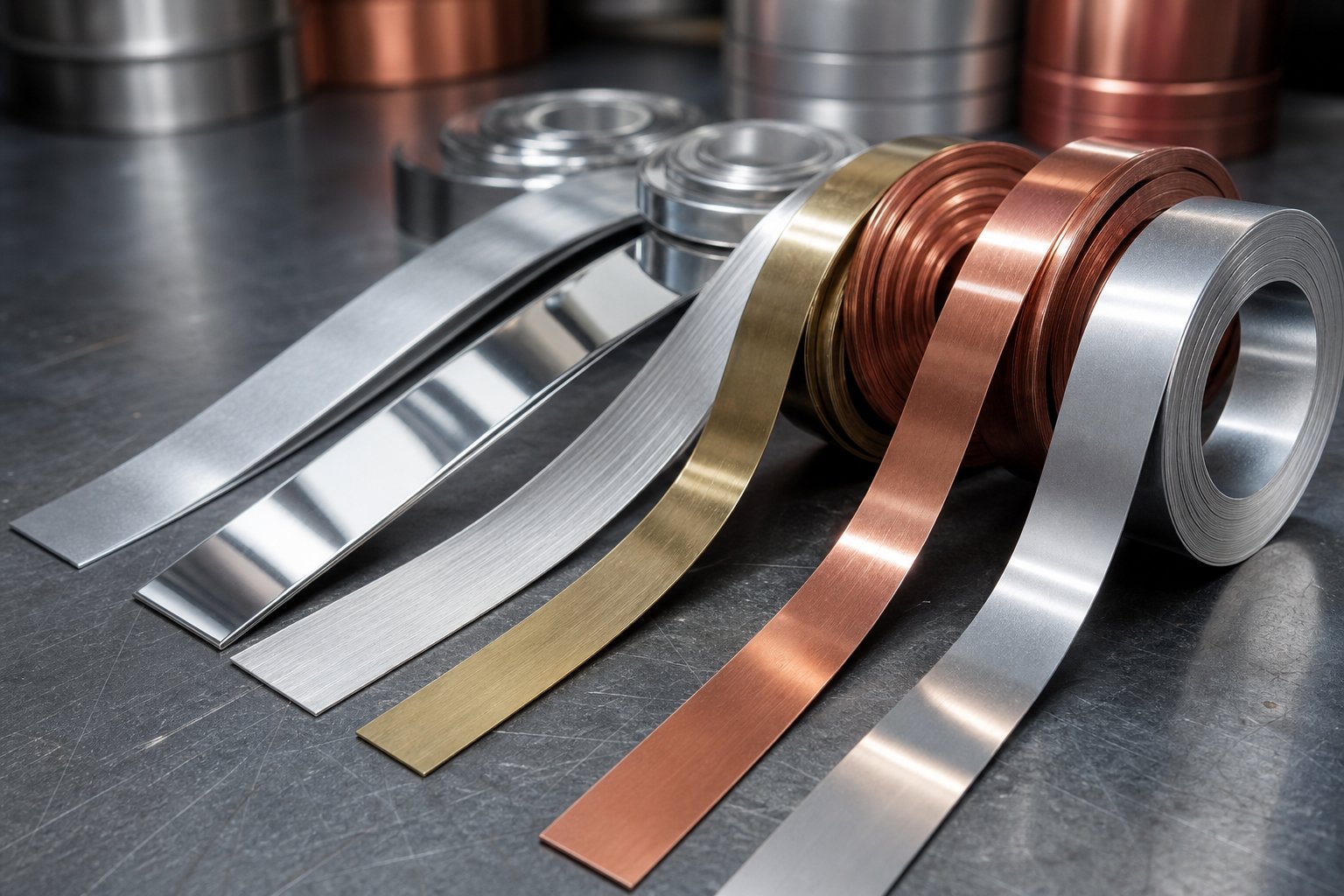
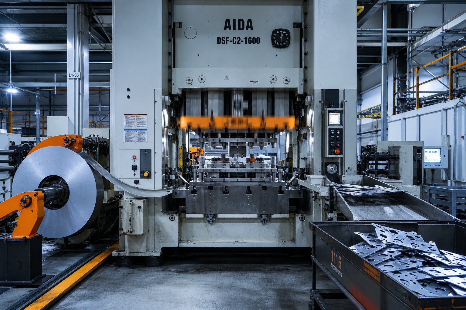
Every progressive die and stamping cycle starts at the uncoiler. A coil of sheet metal - steel, aluminum, copper, brass, or stainless - is loaded onto a mandrel that rotates to release material as the press demands it. The strip first passes through a straightener, which removes the natural curve (called coil set) introduced during winding. Without this step, the strip would feed unevenly and produce dimensional drift across your parts.
From the straightener, a servo feeder pulls the strip into the die at a precise increment called the feed pitch. Feed accuracy here matters more than most buyers realize. Even a 0.05 mm deviation per stroke compounds across stations, creating misaligned holes, uneven bends, and scrap. The feeder must synchronize perfectly with the press stroke cycle, releasing the strip only when the die is fully open and advancing it the exact same distance every time.
Station Progression From Piercing to Cutoff
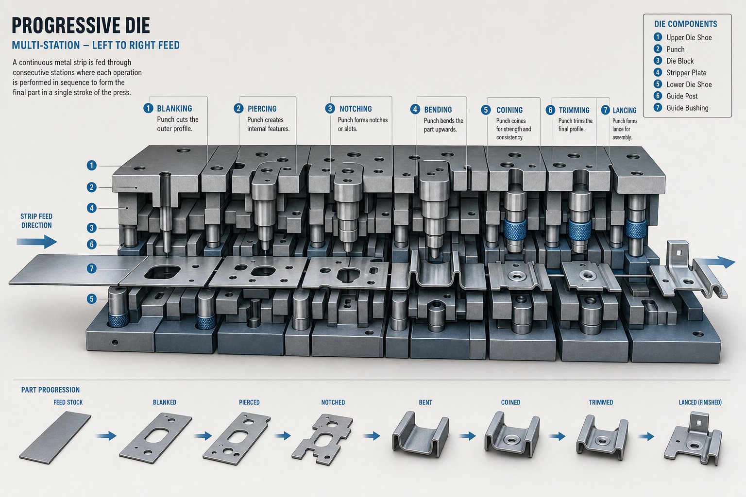
Once inside the progressive stamping die, the strip encounters a sequence of stations - each performing one specific operation. The part stays connected to a carrier strip (sometimes called the web) throughout the entire process, which keeps it stable and accurately positioned as it moves forward. Think of the carrier as a conveyor built into the material itself.
A typical station sequence in a prog die looks like this:
- Pilot holes - Pierced first to create precise registration points that guide the strip through every subsequent station.
- Piercing - Internal holes, slots, and cutouts are punched into the strip.
- Lancing - Partial cuts create tabs or louvers without fully removing material.
- Forming - Three-dimensional shapes, ribs, or embossed features are pressed into the part.
- Drawing - Material is pulled into shallow cup or channel shapes where needed.
- Coining - High-pressure compression refines surfaces, sharpens details, or calibrates critical dimensions.
- Cutoff - The finished part is separated from the carrier strip and ejected for collection.
Not every part requires all these operations. A simple bracket might need only piercing, bending, and cutoff. A complex electrical connector could demand ten or more stations. The point is that each operation happens in a fixed, engineered sequence - and that sequence never varies from part to part.
Press Mechanics and Stroke Cycle
Here's what makes a progressive stamping press so productive: every single stroke of the ram performs all station operations simultaneously on different sections of the strip. While the first station pierces pilot holes into fresh material, downstream stations are bending, forming, and cutting parts that entered the die several strokes earlier. Multiple parts are always in progress at once.
The die stamping press cycles at a fixed speed measured in strokes per minute (SPM). High speed metal stamping operations on smaller parts can run at 200 to over 1,000 SPM, depending on material thickness, part complexity, and press tonnage. Each stroke advances the strip exactly one pitch length forward. That rhythm - advance, stamp, advance, stamp - produces a finished part with every cycle.
Speed alone doesn't define throughput, though. A well-designed die running at 400 SPM with zero downtime will outproduce a poorly designed one running at 600 SPM that jams every hour. Feed stability, die alignment, lubrication, and scrap ejection all determine whether theoretical speed translates into actual output.
This mechanical logic - fixed stations, controlled feed, simultaneous operations - explains why progressive stamping delivers repeatable parts at volume. But the real engineering challenge isn't running the press. It's designing the die itself: choosing how many stations are needed, what sequence they follow, and how the strip layout manages material stress through every operation.
Tooling Design and Die Engineering Fundamentals
Getting the press to cycle is the easy part. The real intellectual investment in progressive die tooling happens months before the first stroke - during strip layout planning, station sequencing, and material selection for the die itself. These engineering decisions lock in part quality, tool life, and per-piece economics for the entire production run.
Strip Layout and Station Sequencing Logic
How does an engineer decide whether a part needs six stations or fourteen? It starts with the part geometry. Every hole, bend, form, and cutoff requires at least one dedicated station, but the sequence has to respect material behavior. You can't coin a surface after a deep draw without risking distortion. You can't pierce a hole adjacent to a bend that hasn't been formed yet without introducing stress fractures.
Progressive stamping die design relies on a deliberate sequencing logic: operations that create the least material stress happen first, while high-force operations like coining or deep forming come later, after surrounding features are already locked in. Idle stations - positions where no work occurs - are strategically placed to allow the strip to stabilize between aggressive operations, and to provide space for future engineering changes if needed.
Pilot hole placement is another critical factor. These small, precisely pierced holes register the strip at every station, and their position relative to forming features determines how accurately downstream operations land. Research published in the International Journal of Production Research identifies four key factors for evaluating strip layouts: station number efficiency, moment balancing, strip stability, and feed height - each scored and weighted to produce an objective evaluation of competing layout options rather than relying on group consensus.
Design for Manufacturability in Progressive Dies
Part designers have enormous influence over progressive die tooling complexity - and cost - through their geometry choices. A component optimized for progressive stamping can run in a 10-station die. The same part with poorly considered features might demand 16 stations, doubling tooling expense and increasing tolerance accumulation across the strip.
Key DFM principles for progressive stamping dies include:
- Minimum bend radii: Keep inside bend radii at or above 1.0x material thickness to prevent cracking at the bend line. For improved tool life, 1.2x to 1.5x thickness is preferred.
- Hole diameter limits: Maintain hole diameters at or above 1.0x material thickness to avoid punch breakage under high-speed cycling.
- Feature spacing: Keep punched features at least 2.0x material thickness from edges and adjacent features to prevent die steel from collapsing over time.
- Uniform wall thickness: Avoid drastic thickness transitions that create uneven material flow and increase springback unpredictability.
- Grain direction awareness: Orient bends perpendicular to the rolling direction when possible to reduce fracture risk.
- Shallow forming depth: Minimize draw depths relative to part width - excessive depth requires transfer die processes rather than progressive strip-based operations.
Experienced progressive tool and die engineers review part prints early and flag features that add stations, complicate maintenance, or reduce die life. That upfront DFM feedback often saves more money than any sourcing negotiation.
Tooling Construction and Die Materials
The physical construction of a progressive stamping tool determines how many millions of parts it can produce before requiring major refurbishment. Die components endure repeated high-speed impact, friction, and material flow - so material selection for the tooling itself matters enormously.
Most progressive die sets use D2 or A2 tool steel for punches and die inserts. D2 offers excellent wear resistance and edge retention, making it a workhorse for piercing and blanking stations. A2 provides better toughness for forming stations where impact loads are higher but abrasive wear is lower. For applications demanding extreme tool life - stamping abrasive stainless steels at volumes exceeding several million parts - progressive carbide stamping dies with tungsten carbide inserts replace conventional steel at critical wear points. As one industry guideline notes, carbide behaves like concrete: it will disintegrate before it wears, making it ideal for stations where abrasion would rapidly degrade tool steel.
Die plates and shoe sets are typically constructed from S7 or 4140 pre-hardened steel, providing the structural rigidity needed to maintain alignment across all stations under full press tonnage. Guide pins, bushings, and alignment components must be robust enough to overcome the lateral forces generated by off-center forming - a detail that ties directly back to the moment-balancing factor in strip layout evaluation.
Ultimately, tooling material decisions track back to a single question: what's the expected production volume? A 50,000-piece annual run doesn't justify carbide inserts everywhere, while a 5-million-piece program can't afford the downtime of frequent D2 punch replacements. Matching die construction to volume expectations is where engineering judgment and cost optimization intersect - and where the material being stamped introduces its own set of constraints.
Material Selection and How Metals Behave in Progressive Dies
Die construction matters - but the material running through that die dictates nearly every other engineering decision. Strip feed behavior, station sequencing, lubrication strategy, punch clearance, and maintenance intervals all shift depending on what metal you're forming. Buyers who treat material selection as a simple procurement checkbox often discover, mid-production, that their chosen alloy demands a fundamentally different tooling approach than they budgeted for.
Steel and Stainless Steel Stamping Considerations
Carbon steel progressive stamping remains the most common application for progressive dies. Low-carbon grades like 1008 and 1010 offer excellent formability, predictable behavior across stations, and minimal tool wear. They accept tight bends, deep forms, and high-speed cycling without drama. Typical thickness ranges for steel progressive stamping fall between 0.4 mm and 3.0 mm, with thinner gauges running at higher strokes per minute and thicker stock demanding greater press tonnage.
Stainless steel progressive stamping, on the other hand, introduces a completely different set of challenges. Austenitic grades like 304 work-harden aggressively as they pass through forming stations - meaning each successive operation encounters progressively harder material. Engineers must account for this by calculating exponentially higher tonnage at downstream stations and sequencing operations to minimize cumulative strain.
Springback is equally problematic. Where mild steel might spring back 1 to 2 degrees after a bend, stainless routinely springs 3 to 5 degrees or more. Tooling engineers compensate by overbending - machining punch and die angles to 93 degrees, for example, so the part relaxes into the target 90-degree geometry. Without this compensation built into the die design, every bent feature lands out of tolerance.
Galling presents the most disruptive failure mode. High friction strips stainless steel's passive oxide layer, causing exposed material to cold-weld directly onto the tool surface. Once galling starts, production stops for die polishing. PVD coatings like TiCN on punch surfaces and extreme-pressure lubricants are mandatory countermeasures for any stainless program running at volume.
Copper and Brass Alloy Behavior in Progressive Dies
Copper progressive stamping dominates the electrical connector and terminal market, and for good reason. C11000 electrolytic tough pitch copper delivers approximately 101% IACS conductivity alongside excellent ductility, making it ideal for the barrel forms, contact tabs, and crimping features that progressive stamping copper terminals require. Strip coil for these applications typically ranges from 0.13 mm to 1.5 mm thick, with specified temper (annealed through full-hard) directly affecting forming behavior at each station.
The challenge? Copper galls aggressively against tool steel - similar to stainless, but driven by copper's softness and high surface adhesion rather than oxide layer failure. Automated lubrication systems and polished die surfaces are non-negotiable for sustained copper production runs.
Brass progressive stamping offers a practical alternative where full copper conductivity isn't required. C26000 cartridge brass provides higher strength and better spring properties for retention clips, while its lower friction coefficient makes it significantly friendlier to tooling than pure copper. Phosphor bronze (C51000) fills the gap for applications needing both spring force and moderate conductivity - think connector contacts that must maintain consistent pressure over thousands of mating cycles.
Work hardening in copper alloys follows a different curve than steel. These materials harden rapidly during initial forming but plateau earlier, which means multi-station progressive sequences must front-load the heaviest deformation before the alloy stiffens. Engineers often specify annealed temper strip specifically so that early stations can form aggressively without fracturing the material at downstream operations.
Aluminum Progressive Stamping Challenges
Aluminum progressive stamping appeals to weight-sensitive applications - automotive heat shields, electronics enclosures, aerospace brackets - where density savings justify the extra engineering effort. Alloys like 5052-H32 and 6061-T4 offer reasonable formability in the 0.5 mm to 3.0 mm thickness range, but they introduce stamping behaviors that catch buyers off guard.
Galling tops the list again. Aluminum's soft oxide layer breaks down under forming pressure, exposing fresh material that bonds instantly to tool steel. Unlike stainless, where specialized coatings solve most issues, aluminum galling often requires a combination of approaches: chromium-plated die surfaces, PTFE-based dry-film lubricants, and increased die clearances (typically 8% to 12% of material thickness versus 5% to 8% for steel).
Those wider clearances exist because aluminum tears rather than shears cleanly when punch-to-die gaps are too tight. Burr control becomes a balancing act - too tight and you get tearing and excessive punch wear, too loose and burr height exceeds acceptable limits for downstream assembly.
Lubrication requirements are also more demanding. Standard stamping oils that work perfectly for carbon steel often lack the boundary-layer properties aluminum needs. Without proper lubrication, surface scoring and die buildup accumulate within a few hundred strokes, forcing unplanned maintenance stops.
| Material Family | Formability | Typical Thickness Range | Common Applications | Key Stamping Considerations |
|---|---|---|---|---|
| Low-Carbon Steel (1008/1010) | Excellent | 0.4 – 3.0 mm | Brackets, clips, structural reinforcements, automotive hardware | Minimal springback; low tool wear; highest speed capability |
| Stainless Steel (304/316L) | Moderate | 0.3 – 2.5 mm | Medical components, food equipment, corrosion-resistant housings | Severe springback; work hardening; galling requires PVD coatings and EP lubricants |
| Copper (C11000) | Excellent | 0.13 – 1.5 mm | Electrical terminals, bus bars, connectors | Galling tendency; softness causes die buildup; temper selection critical |
| Brass (C26000) | Very Good | 0.2 – 2.0 mm | Connector springs, decorative hardware, instrument components | Lower galling risk than copper; better spring retention; moderate work hardening |
| Aluminum (5052/6061) | Good | 0.5 – 3.0 mm | Heat shields, enclosures, lightweight brackets, heat sinks | Wider die clearances required; PTFE lubricants; tears rather than shears if clearance is tight |
Each material imposes its own rules on die clearance, station count, lubrication, and maintenance frequency. The part print might look identical in steel versus aluminum, but the progressive die behind it - and the cost to build and maintain it - can differ dramatically. That difference only sharpens when you start comparing how these materials perform against alternative stamping methods that handle them in fundamentally different ways.
Progressive Die vs Transfer Die vs Compound Die
Material behavior shapes the die - but the type of die you choose shapes the entire production strategy. Buyers often assume that progressive dies handle everything, or that all dies and stamping methods are interchangeable with minor cost differences. In reality, progressive dies, transfer dies, and compound dies each solve fundamentally different manufacturing problems. Picking the wrong one doesn't just waste tooling budget - it locks you into a process that fights your part geometry for the life of the program.
| Characteristic | Progressive Die | Transfer Die | Compound Die |
|---|---|---|---|
| Process Mechanics | Part stays attached to carrier strip through all stations | Part is separated from strip early, moved between stations by mechanical fingers | Multiple cutting operations performed in a single stroke |
| Ideal Part Complexity | Small to medium parts with moderate forming, bends, and pierced features | Large or deep-drawn parts requiring extensive forming or orientation changes | Flat parts needing only blanking, piercing, or simple shearing |
| Volume Suitability | 50,000+ units/year (optimal above 100,000+) | 25,000+ units/year | Medium to high volumes of simple geometries |
| Cycle Speed | 200–1,000+ strokes per minute | Moderate (mechanical transfer limits speed) | Fast for simple parts; slower for larger components |
| Tooling Cost | High ($30,000–$250,000+) | High (comparable to progressive) | Lower - simpler construction, fewer stations |
| Per-Part Cost at Volume | Lowest for qualifying geometries | Low, but higher than progressive due to slower cycle | Low for flat parts; not applicable to formed parts |
Progressive Die vs Transfer Die Stamping
The core distinction is simple: in progressive dies, the part never leaves the strip until the final cutoff station. In transfer die stamping, the part is separated from the strip at the very first operation, then physically moved between stations by mechanical fingers or a transfer mechanism.
Why does that matter? Because the carrier strip limits draw depth. If your part requires deep forming - cups, shells, or enclosures taller than about 1.5x the part diameter - the strip will tear or buckle before the forming operation completes. Transfer dies eliminate that constraint entirely. Once the blank is free from the strip, the press can draw as deeply as the material's elongation properties allow.
Transfer dies also handle larger parts that require orientation changes between stations, like automotive body panels or deep-drawn housings that need rotation for multi-axis forming. Progressive dies can't rotate a part - it's physically locked to the strip throughout.
The tradeoff? Speed. Transfer mechanisms need time to grip, move, and release each blank. That mechanical reset means transfer presses typically run at lower strokes per minute than progressive operations on equivalently sized parts. For small, high-volume components - electrical terminals, spring clips, thin brackets - progressive dies win on throughput by a wide margin. For larger structural components or anything requiring draw depths beyond strip carrier limits, transfer stamping is the only viable path.
Volume crossover points also differ. Progressive die metal stamping typically becomes cost-justified at 50,000 to 100,000+ annual units, while transfer die programs can justify tooling investment at volumes as low as 25,000 units, partly because the larger parts produced carry higher per-piece value.
Progressive Die vs Compound Die
Compound dies operate on a completely different principle. Rather than sequencing operations across multiple stations, a compound die performs several cutting operations simultaneously in a single press stroke. The strip goes in, one stroke fires, and a fully blanked and pierced flat part drops out.
Sounds efficient - and for the right application, it is. Compound die stamping produces flatter parts with better dimensional accuracy between features because all cut edges are created in one action, eliminating misalignment between separate operations. Washers, shims, gaskets, and flat electrical laminations are textbook compound die applications.
The limitation is fundamental: compound dies can only cut. They lack forming capability. No bending, no drawing, no embossing. If your part requires any three-dimensional geometry - even a simple 90-degree tab - compound dies can't produce it. You'd need a secondary bending operation downstream, which adds handling, cost, and quality risk.
Compound tooling is also less expensive and faster to build than progressive tooling, making it the economical choice for flat parts at medium volumes where precision die stamping of simple geometries is the requirement. But the moment part complexity demands forming, the compound die hits a hard ceiling - and progressive dies become necessary.
When Progressive Die Stamping Is the Optimal Choice
Not every part belongs in a progressive die. The decision depends on five intersecting criteria:
- Part size: Progressive dies favor small to medium components that fit within standard strip widths (typically under 300 mm).
- Geometry complexity: Parts requiring multiple operations - piercing plus forming plus bending - benefit most from the sequential station approach.
- Annual volume: The high upfront tooling cost only makes sense when amortized across tens or hundreds of thousands of parts.
- Tolerance demands: Strip-based progression with pilot hole registration delivers consistent tolerances of ±0.05 mm to ±0.10 mm across millions of cycles.
- Secondary operation elimination: If a progressive die & stamping approach can consolidate what would otherwise require multiple setups, it reduces total program cost even if tooling is expensive.
Progressive dies become the most economical choice when annual volumes exceed 50,000 units and part geometry requires multiple forming operations that would otherwise demand separate tooling setups, manual handling, or secondary processes.
Below that volume threshold, simpler methods - compound dies for flat parts, CNC laser cutting for prototypes, or even single-station dies for low-complexity shapes - deliver better cost-per-part economics. Above it, progressive dies dominate because per-unit cost drops toward raw material plus press time, while every alternative carries linear labor or cycle-time penalties that compound with volume.
The right choice also depends on program longevity. A part with a five-year production life at 80,000 units per year (400,000 total) justifies premium tooling construction - carbide inserts, hardened guide systems, quick-change components - that a two-year, 60,000-unit program might not. Matching die investment to total lifetime volume, not just annual demand, separates smart sourcing decisions from expensive mistakes.
Understanding which process fits your part is only the first step. The next question most buyers underestimate is how industry-specific requirements - certifications, documentation standards, material traceability - layer additional demands onto what seems like a straightforward stamping decision.
Industries That Rely on Progressive Die Stamping
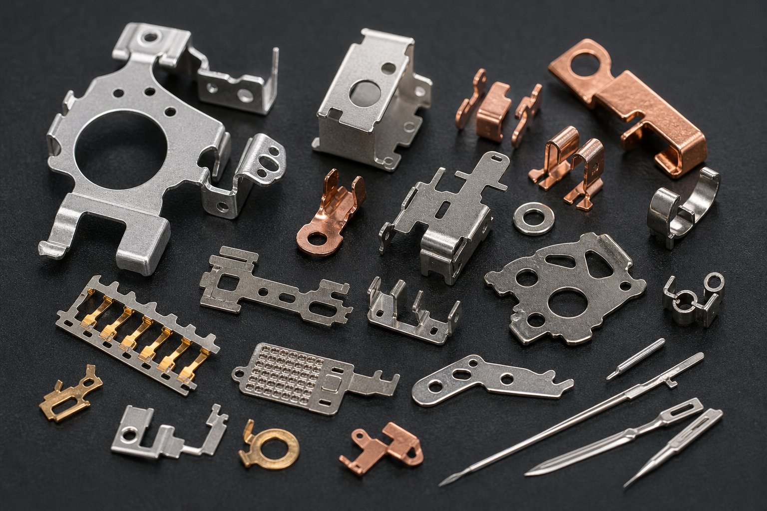
Every industry stamps metal. But the reason each industry chooses progressive die stamping over alternatives comes down to specific technical demands that other processes simply can't match at scale. Listing "automotive, medical, electronics" tells you nothing useful. What matters is why these sectors require the particular combination of speed, repeatability, and geometric complexity that progressive dies deliver.
Automotive High-Volume Consistency Requirements
Automotive programs don't just demand parts - they demand documented proof that every part is identical to the last million. That's why automotive components progressive stamping operates under IATF 16949 certification, which requires PPAP documentation, statistical process control (SPC), measurement system analysis (MSA), and failure mode and effects analysis (FMEA) throughout production.
Progressive dies deliver the repeatability these programs require because the process is inherently self-registering. Pilot holes align every stroke identically, and the strip carrier eliminates part handling variation between operations. When you're producing 500,000 brackets per year for a door latch assembly, that mechanical consistency is what keeps your Cpk values above 1.33 without constant operator intervention.
Typical automotive parts produced through progressive stamping include:
- Structural reinforcement brackets and mounting plates
- Window regulator clips and spring retention components
- Electrical connector housings and terminal contacts
- Seat frame brackets and safety system hardware
- Engine knock sensor housings and solenoid valve components
The combination of high volume, tight tolerances, and mandatory documentation makes progressive stamping the default process for any automotive stamped component small enough to run on a strip.
Medical Device Micro-Tolerance Applications
Medical device progressive stamping operates at the opposite end of the size spectrum - but with equal or greater precision demands. As devices shrink toward minimally invasive designs, the components inside them follow. Surgical instrument jaws, implantable clip features, and diagnostic sensor brackets now require tolerances measured in micrometers, not tenths of millimeters.
What makes medical progressive stamping particularly demanding is the intersection of three constraints. First, biocompatible materials - 316L stainless steel, titanium, cobalt-chromium alloys - are harder to form and more abrasive to tooling than standard carbon steel. Second, micro stamping for implantable devices requires specialized tooling and precision control systems that push beyond traditional stamping equipment capabilities. Third, clean manufacturing environments and full material lot traceability add process overhead that doesn't exist in commercial stamping programs.
High precision metal stamping for medical applications routinely achieves tolerances of ±0.01 mm to ±0.025 mm on critical features - possible because progressive dies eliminate the repositioning errors inherent in multi-setup processes. Common medical components include:
- Surgical staple and clip blanks
- Catheter tip reinforcement bands
- Hearing aid battery contacts and housings
- Orthodontic bracket bases
- Diagnostic strip electrode contacts
Electronics and HVAC Applications
Electronics manufacturers rely on progressive precision metal stampings for one straightforward reason: connector pins, shield cans, and contact springs are too small and too geometrically complex to produce economically any other way. A single smartphone connector might contain dozens of stamped terminals, each with formed barbs, contact dimples, and solder tails produced in a 12-station progressive die running at 800+ strokes per minute.
Typical electronics stampings include:
- USB and board-to-board connector terminals
- EMI shielding cans and grounding clips
- LED heat sink fins and thermal interface components
- Battery contact springs
HVAC progressive stamping addresses a different problem - not miniaturization, but sheer volume at low cost. HVAC systems consume enormous quantities of relatively simple stamped components: mounting brackets, fan motor end bells, heat exchanger fins, and ductwork fasteners. These parts don't require medical-grade tolerances, but they demand millions of pieces annually at price points that only high-speed progressive operations can achieve.
Common HVAC stampings produced in progressive dies:
- Condenser and evaporator fin arrays
- Compressor valve plates and reed valves
- Mounting brackets and motor laminations
- Heat exchanger tube support plates
Each of these industries arrives at progressive die stamping from a different direction - automotive through documentation rigor, medical through micro-tolerance necessity, electronics through miniature complexity, and HVAC through pure volume economics. But they all share one common vulnerability: underestimating how much the cost structure shifts when industry-specific requirements layer onto base stamping economics.
Cost Drivers and Economics of Progressive Stamping
Industry-specific requirements add cost layers - but many buyers misread the base economics before those layers even enter the picture. Progressive die stamping services carry a cost structure that looks nothing like commodity purchasing. The upfront number is large. The per-part number is tiny. And the relationship between those two figures confuses procurement teams who evaluate tooling quotes the same way they evaluate raw material bids.
Tooling Investment vs Per-Part Cost Economics
Here's the fundamental tension: progressive die tooling typically ranges from $30,000 to over $250,000 depending on complexity. That's a significant capital outlay before a single production part exists. But once that die is running, the marginal cost of each additional part drops to little more than raw material plus press time.
What drives tooling cost upward? Station count, primarily. A six-station pierce-and-bend die in mild steel might land between $10,000 and $25,000. Add forming operations, tighter tolerances, carbide inserts for abrasive materials, or in-die sensing packages, and you're looking at $25,000 to $60,000 for medium-complexity tooling - which is where most automotive and electronics applications concentrate. High speed progressive die stamping dies with deep drawing, in-die tapping, or heavy stamping operations on thick-gauge materials push well beyond that range.
The payoff? Per-part cost reductions of 60% to 80% compared to discrete manufacturing methods. A mounting bracket that costs $5.00 per unit through laser cutting with manual secondary operations drops to roughly $0.50 per unit through progressive stamping. That spread is what makes the upfront investment worthwhile - but only at volume.
Volume Thresholds and Break-Even Considerations
When does progressive die stamping become the economical choice? The commonly cited threshold is 50,000 annual units, though ultra-simple parts may justify tooling at 30,000 units. Below this range, the die cost divided by unit count overwhelms per-part savings. Above it, long run progressive stamping amortizes that tooling investment rapidly - often achieving payback within 6 to 18 months of production.
Consider the math directly. A $50,000 die producing 500,000 parts adds just $0.10 per unit in tooling cost. That same die producing only 5,000 parts adds $10.00 per unit - turning an efficient process into an economic disaster. OEM progressive stamping programs running multi-year contracts at six-figure annual volumes push the tooling contribution toward fractions of a penny per part, making high volume stampings the territory where progressive dies deliver their strongest returns.
Hidden Cost Factors Buyers Should Understand
The die quote and per-part price don't tell the whole story. Experienced buyers account for cost drivers that never appear on the initial quotation - and these hidden factors often determine whether a program stays on budget or spirals beyond it.
- Tolerance requirements: Features held below ±0.05 mm demand frequent die sharpening and higher-grade tool steels, inflating both tooling and maintenance cost significantly.
- Material utilization rate: Strip layout efficiency determines how much of your purchased coil becomes finished parts versus scrap. Poor nesting can waste 30%+ of raw material.
- Engineering changes after die construction: A late-stage design change can cost as much as half the original tool price - rework of machining, heat treatment, and grinding adds up fast.
- Secondary operations: Tapping, plating, heat treating, or assembly steps that the die can't consolidate add per-piece labor and handling cost at volume.
- Development and tryout iterations: Medium-complexity dies commonly require 5 to 8 sampling iterations before achieving stable production. Those trial runs consume press time, engineering hours, and material that rarely appear in the original quote.
- Die maintenance over production life: Punch resharpening, insert replacement, and preventive overhauls are ongoing expenses that scale with total part count.
The procurement discipline that works for commodity purchases - lowest compliant bid wins - fails for progressive die programs. A $22,000 quote that excludes robust simulation, adequate tryout scope, and proper die class construction often generates $15,000 or more in downstream development costs that a $35,000 quote with thorough front-end engineering would have avoided entirely.
Smart buyers evaluate total cost of ownership: tooling plus development plus maintenance plus per-part price across the full program life. That calculation shifts attention from the purchase order to the production economics - and raises the more practical question of how to identify suppliers capable of delivering those economics reliably.
How to Evaluate a Progressive Die Stamping Supplier
Total cost of ownership tells you what to spend. Supplier evaluation tells you who deserves it. And this is where many procurement teams stumble - they compare quotes line by line without verifying whether the progressive stamping company behind those numbers can actually deliver the engineering depth, quality infrastructure, and production scalability the program demands.
Technical Capabilities to Verify
The single biggest differentiator among progressive die manufacturers is whether they design and build tooling in-house or subcontract it. A supplier with internal die engineering can iterate on strip layouts, modify station sequencing, and troubleshoot tryout issues in days rather than weeks. When your tool builder and your production floor share the same roof, DFM feedback happens in real time - not through email chains between disconnected companies.
Beyond tooling capability, verify these specifics before shortlisting any progressive die stampings suppliers:
- Press tonnage and bed size range: Does their equipment match your part's material thickness and footprint? A supplier running 30-ton presses can't handle thick stainless components that need 150+ tons of forming force.
- Material handling capacity: Can they process the coil widths, thicknesses, and alloys your part requires? Servo feed systems, coil straighteners, and in-line lubrication all affect what materials they can run reliably.
- Secondary operations: Tapping, welding, plating, heat treating, and assembly performed under one roof eliminate logistics cost and quality risk between process steps.
- Multi-station forming expertise: Suppliers like YICHEN, which explicitly serves production engineers and procurement teams sourcing progressive stamping dies for high-volume metal parts, demonstrate the kind of focused capability - efficient multi-station forming, tight repeatability, and scalable mass production - that separates a qualified partner from a general job shop.
A supplier invested in advanced CNC machining, wire EDM, and digital simulation tools like Finite Element Analysis (FEA) can predict and resolve tooling issues before steel is even cut. That technological proficiency directly translates to fewer tryout iterations, shorter lead times, and lower total development cost.
Quality Systems and Certifications That Matter
Certifications aren't just logos on a website. Each one imposes specific process discipline that affects how your parts are produced, inspected, and documented:
| Certification | Scope | What It Means for Your Stamped Parts |
|---|---|---|
| ISO 9001 | General manufacturing quality | Baseline process control, risk-based thinking, continual improvement. Sufficient for general industrial stampings. |
| IATF 16949 | Automotive production | Mandates PPAP, SPC, FMEA, and MSA. Required for any automotive tier supplier. Enforces Cpk ≥ 1.67 on critical characteristics. |
| AS9100 | Aerospace and defense | Adds configuration management, first article inspection per AS9102, and counterfeit parts prevention. Non-negotiable for aerospace primes. |
For automotive programs, PPAP (Production Part Approval Process) is the gateway to production. A typical progressive die stamping PPAP takes 8 to 12 weeks from tool kick-off to approved Part Submission Warrant. That timeline covers die fabrication, first article runs, dimensional validation, capability studies, and the full 18-element submission package. If a progressive die manufacturer can't articulate their PPAP process clearly, they haven't run enough automotive programs to handle yours.
For non-automotive work, you can still request a subset: dimensional reports, material certificates, control plan, and sample parts. The structure provides accountability even when the full automotive documentation burden isn't required.
Questions to Ask Your Stamping Supplier
Knowing what to verify is one thing. Getting honest answers requires asking pointed questions. Use this checklist when evaluating stamping die manufacturers - it covers the gaps where superficial quotes hide real capability differences:
- Tooling ownership: Who owns the die after payment - you or the supplier? Can you transfer it to another facility if needed?
- In-house die engineering: Do they design, simulate, and build progressive dies internally, or subcontract any stage?
- DFM feedback process: Will they review your part design and suggest modifications for stampability before quoting tooling? How quickly?
- Volume scalability: Can they scale from initial sampling to 500,000+ annual units without outsourcing press capacity?
- Material sourcing: Do they stock standard coil alloys, or does every order require lead time for material procurement?
- Tryout and validation scope: How many sampling iterations are included in the tooling quote? What happens if additional tryouts are needed?
- Die maintenance program: What's their preventive maintenance schedule? Who bears the cost of punch resharpening and insert replacement over the die's lifetime?
- Engineering change process: How do they handle mid-production design revisions? What's the typical cost and timeline impact?
- Quality documentation: Can they provide PPAP Level 3, first article inspection reports, and ongoing SPC data as standard deliverables?
- Communication and project management: Will you have a dedicated technical contact, or are you routed through general sales?
A supplier who answers these questions with specifics - actual timelines, named engineering contacts, documented processes - is signaling depth. One who deflects toward generic reassurances is signaling risk. Among metal stamping die manufacturers, the difference between a reliable long-term partner and a source of recurring production headaches often becomes visible at this evaluation stage, well before any purchase order is signed.
Supplier selection sets the foundation. But understanding how the project actually unfolds - from that first design review through production ramp - determines whether your timeline expectations are realistic or wishful thinking.
From Initial Inquiry to Full Production
You've identified the right supplier. The evaluation questions checked out. So what actually happens next? Most buyers enter progressive die metal stamping services programs with a vague sense that tooling gets built, samples get approved, and production starts. The reality is a structured sequence of engineering gates, each with its own timeline, deliverables, and potential failure points. Misunderstanding this lifecycle is where schedule overruns originate - not from supplier incompetence, but from buyer expectations that skip critical phases.
Design Review and DFM Feedback Stage
Every progressive metal stamping project begins with an engineering assessment - not a purchase order. The supplier's tooling engineers review your part geometry, material selection, tolerance callouts, and annual volume targets to determine whether the component is a fit for progressive die processing at all. This is where they flag features that add unnecessary stations, suggest radius changes that prevent cracking, and identify opportunities to consolidate secondary operations into the die itself.
Expect this phase to include:
- Strip layout concepts showing station count, carrier design, and feed pitch
- Preliminary press selection based on tonnage calculations and bed size requirements
- DFM recommendations - geometry modifications that reduce tooling cost or improve die life
- Material confirmation, including discussion of progressive stamping materials behavior and any alloy-specific tooling requirements
- Budgetary tooling and piece-price estimates tied to specific volume assumptions
Typical duration? Two to four weeks for standard complexity parts. Highly complex components with tight tolerances or exotic materials may take longer as engineers run forming simulations and evaluate multiple strip layout alternatives before committing to a direction. Rushing this phase - or skipping DFM feedback entirely - is the single most common mistake buyers make. Every dollar saved in engineering review generates ten dollars in tooling rework downstream.
Tooling Construction Through First Article Approval
Once strip layout and part design are locked, die construction begins. A high-quality progressive die typically requires 12 to 20 weeks to design, machine, heat treat, grind, assemble, and commission. Complex dies with many stations or tight tolerances may push beyond that range. This timeline isn't padding - it reflects the reality of precision die and stamping tooling that must maintain dimensional accuracy across millions of cycles.
The construction-to-approval sequence generally follows this path:
- Detailed die design: Full 3D modeling of every station, component, and strip progression (2-4 weeks)
- Component machining: CNC milling, wire EDM, and grinding of punches, die inserts, and plates (4-8 weeks)
- Heat treatment and finishing: Hardening die steels to specified Rockwell values, surface grinding to final dimensions (1-2 weeks)
- Assembly and bench fitting: Installing components, setting clearances, verifying alignment across all stations (1-2 weeks)
- First tryout: Initial press runs to validate strip progression, identify interference, and produce preliminary samples
- Iteration and refinement: Adjusting punch heights, modifying forming radii, correcting dimensional deviations based on sample measurement
- First article inspection: Full dimensional report against the part print, often including GD&T measurements on critical features
For automotive programs, this phase culminates in PPAP submission - a comprehensive documentation package that demonstrates process capability through dimensional data, capability studies (Cpk analysis), control plans, and a Part Submission Warrant. PPAP Level 3, the most commonly required submission level, includes full documentation of engineering drawings, process flow, capability studies, and production samples produced under normal conditions.
Medium-complexity dies commonly require 5 to 8 sampling iterations before achieving stable production-ready quality. Each iteration involves running parts, measuring them, identifying deviations, modifying tooling, and re-running. Buyers who budget for two tryouts and then discover they need six are the ones calling their supplier in frustration at week 18 - when the schedule assumed production would already be running.
Production Ramp and Ongoing Quality Management
First article approval doesn't mean full production starts the next day. There's a deliberate ramp period where production rates increase incrementally while the supplier validates that quality remains stable at speed. Running a die at 50 strokes per minute during tryout tells you the tool works. Running it at 400 SPM for eight consecutive hours tells you whether it can sustain production without thermal drift, lubrication breakdown, or scrap accumulation issues.
During steady production, quality management relies on three pillars:
- Statistical process control (SPC): Critical dimensions are measured at defined intervals and charted to detect drift before parts go out of tolerance. Control limits trigger corrective action well before defective parts reach your dock.
- Preventive die maintenance: Scheduled shutdowns for punch resharpening, insert inspection, and spring replacement prevent unplanned failures. Most progressive dies require maintenance every 50,000 to 150,000 strokes depending on material abrasiveness and tool construction.
- Production monitoring: In-die sensors, tonnage monitors, and mis-feed detectors stop the press instantly if something goes wrong - protecting both the tooling investment and part quality.
For production engineers and procurement teams ready to begin their progressive stamping die sourcing journey, suppliers like YICHEN focus specifically on tight repeatability and scalable mass production - capabilities that matter most during this production ramp phase, where the die must prove it can deliver consistent parts not just in sampling, but across sustained high-volume runs.
The full lifecycle - from first inquiry to stable production - typically spans 16 to 30 weeks depending on part complexity, material challenges, and documentation requirements. Buyers who understand this timeline upfront plan their product launches accordingly. Those who don't end up compressing engineering phases, skipping validation steps, and paying for it in quality escapes and schedule delays that cost far more than the weeks they tried to save.
Frequently Asked Questions About Progressive Die Metal Stamping
1. What is a progressive die in metal stamping?
A progressive die is a multi-station tool installed in a stamping press where a continuous metal strip advances through sequential stations with each press stroke. Each station performs a specific operation such as piercing, bending, forming, or cutting. The part remains attached to a carrier strip throughout the process and is separated only at the final cutoff station, producing a completed component with every stroke cycle.
2. How much does progressive die tooling cost?
Progressive die tooling typically ranges from $30,000 to over $250,000 depending on station count, material requirements, tolerance demands, and features like carbide inserts or in-die sensors. A simple six-station pierce-and-bend die in mild steel may cost $10,000 to $25,000, while medium-complexity automotive or electronics tooling usually falls between $25,000 and $60,000. The investment becomes economical when amortized across annual volumes exceeding 50,000 units, where per-part cost drops significantly compared to alternative processes.
3. What is the difference between progressive die and transfer die stamping?
In progressive die stamping, the part stays connected to the metal strip carrier through all stations until final cutoff. In transfer die stamping, the part is separated from the strip early and physically moved between stations by mechanical fingers. Transfer dies suit larger parts or those requiring deep draws and orientation changes, while progressive dies excel at smaller, high-volume components running at higher strokes per minute. Progressive dies typically become cost-effective above 50,000 annual units, whereas transfer die programs can justify investment at volumes as low as 25,000 units.
4. What materials can be used in progressive die stamping?
Common materials include low-carbon steel (1008/1010), stainless steel (304/316L), copper (C11000), brass (C26000), phosphor bronze (C51000), and aluminum alloys (5052/6061). Each material requires specific tooling adjustments. Steel offers excellent formability with minimal tool wear. Stainless steel demands springback compensation and anti-galling coatings. Copper and brass need specialized lubrication to prevent die buildup. Aluminum requires wider die clearances and PTFE-based lubricants to prevent tearing and surface scoring.
5. How long does it take from initial inquiry to full production with progressive die stamping?
The full lifecycle typically spans 16 to 30 weeks depending on part complexity and documentation requirements. The DFM review phase takes two to four weeks, die construction requires 12 to 20 weeks including design, machining, heat treatment, and assembly, and first article approval involves 5 to 8 sampling iterations. After approval, a production ramp phase validates quality at full speed before steady-state manufacturing begins. Suppliers like YICHEN that focus on tight repeatability and scalable mass production can streamline this timeline through in-house tooling design and construction capabilities.


