


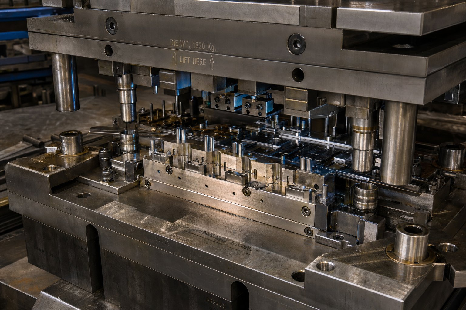
What Stamping Die Design Actually Involves
Imagine taking a flat sheet of steel and turning it into a finished automotive bracket, an electrical connector, or a structural component, all in a fraction of a second. That transformation is what stamping die design makes possible. Yet engineers routinely underestimate how much early design decisions shape everything downstream, from part quality to tooling cost to production uptime.
Stamping die design is the engineering discipline of creating precision tooling that cuts and forms sheet metal into a desired shape through controlled plastic deformation, using force from a mechanical or hydraulic press.
Defining Stamping Die Design in Metal Forming
So what is metal stamping at its core? A stamping die is a custom-built tool, typically made from hardened tool steel, that applies force to flat sheet metal and reshapes it into finished geometry. The process is classified as cold forming, meaning no external heat is introduced intentionally. Friction during cutting and forming generates heat, but the material transformation relies on mechanical force alone.
Every design choice, from punch geometry to clearance values to station sequencing, directly determines edge quality, dimensional accuracy, and how many parts that die can produce before maintenance is required. Research in manufacturing cost analysis suggests that over 70 percent of a part's total cost is locked in during early design decisions. In sheet metal stamping, those decisions live inside the die.
Why Die Design Fundamentals Matter for Every Stamped Part
Getting the fundamentals wrong does not just produce a bad part. It cascades into scrap, rework, press downtime, and tooling rebuilds that blow past budget and schedule. Engineers who master the core principles, die type selection, clearance methodology, station sequencing, and material flow control, avoid the expensive trial-and-error loops that plague under-designed tooling.
This article bridges textbook theory with actionable methodology. You will walk through a structured framework covering die types, component functions, clearance principles, progressive die logic, defect prevention, simulation workflows, and material selection, each section built to fill gaps that standard references leave open.
Choosing the Right Die Type for Your Application
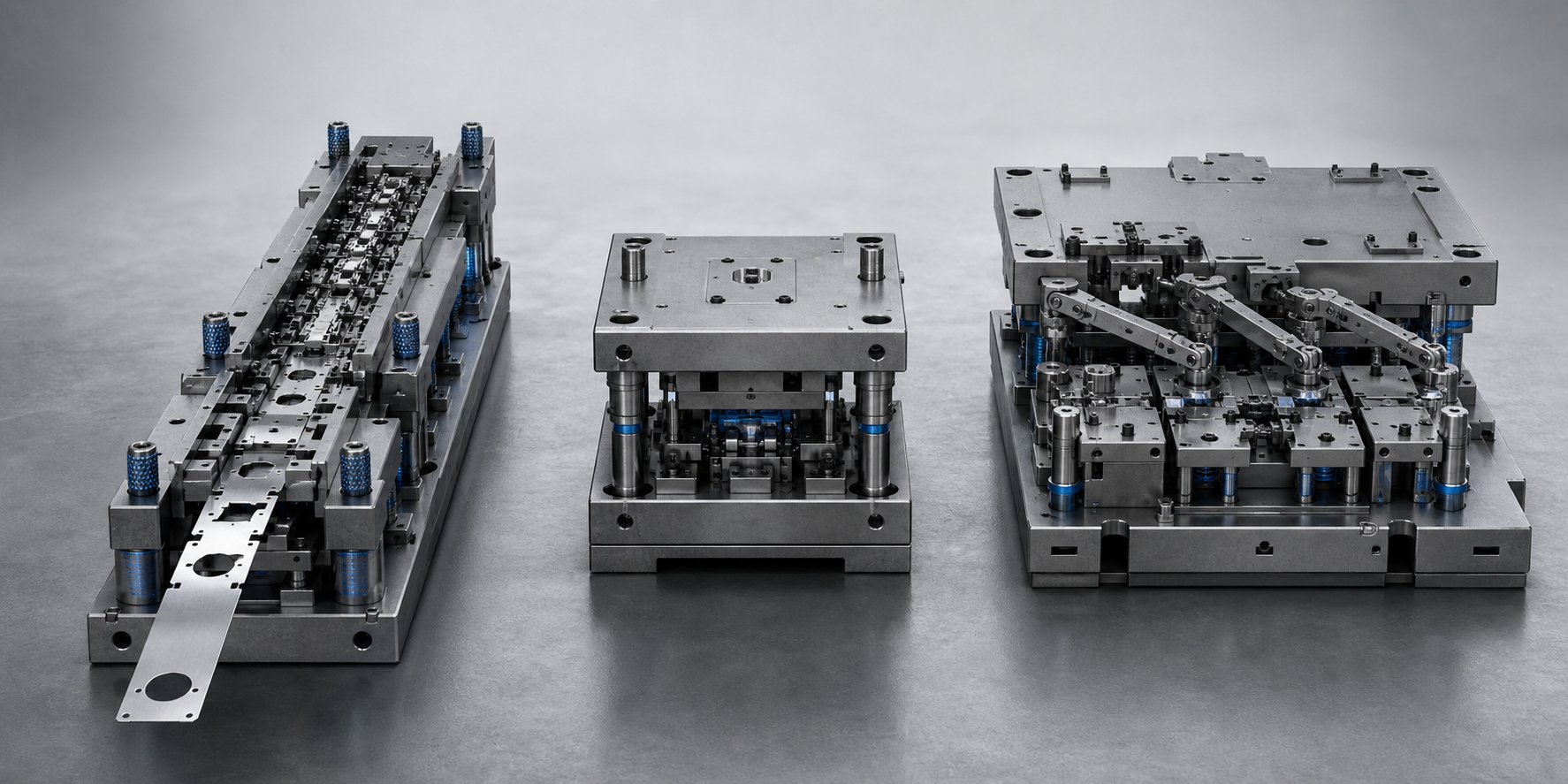
Die type selection is one of those decisions that looks straightforward on paper but quietly determines whether a project hits its cost and quality targets. Pick the wrong architecture and you are either overspending on tooling for a simple part or struggling to hold tolerances with a die that was never designed for your geometry. Three primary types of stamping dies dominate production floors: progressive, compound, and transfer. Each solves a different engineering problem, and understanding where they excel prevents the kind of mismatches that send projects back to the drawing board.
Progressive Dies for High-Volume Continuous Production
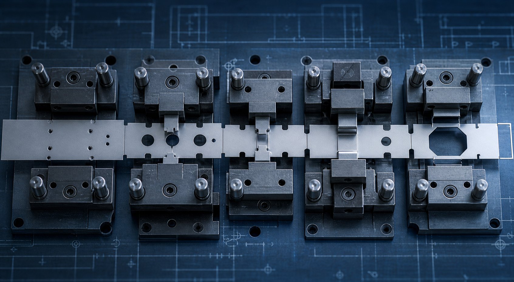
A progressive stamping die is essentially a miniature production line contained within a single tool. A coil of sheet metal feeds into the die as a continuous strip, advancing a fixed pitch with each press stroke. Every station along the strip performs a distinct operation, punching a pilot hole, piercing a feature, notching a profile, bending a flange, until a finished part separates at the final station. Each stroke produces a completed component.
This continuous feed approach delivers exceptional throughput. Press speeds can reach several hundred strokes per minute, and because the strip remains connected throughout, no manual handling is required between operations. The tradeoff is a higher upfront tooling investment and a limited flexibility for design changes once the die is built. Progressive dies shine when production volumes justify that investment, typically in runs of hundreds of thousands to millions of parts, and when the part geometry is small to medium in size with multiple features that can be sequenced across stations.
Compound Dies for Tight-Tolerance Flat Parts
When your part is relatively flat and demands exceptional concentricity or positional accuracy between features, a compound die is the precision tool for the job. Unlike progressive dies that work through sequential stations, a compound die performs two or more cutting operations simultaneously in a single press stroke at a single station. A classic example: blanking the outer profile and piercing an inner hole at the same instant.
Because all cutting happens in one closure, the relative positional accuracy between inner and outer contours is inherently superior. Part flatness also benefits since there is no cumulative deformation from multiple station transfers. Think gaskets, precision washers, instrument components, and lamination discs. The limitation is that compound dies handle cutting operations only. They cannot bend or draw material, which restricts them to 2D profiles. Tooling costs sit below progressive dies, making them a strong fit for small to medium production volumes where precision outweighs throughput speed.
Transfer Dies for Large or Deep-Drawn Geometry
Some parts are simply too large or require too much three-dimensional forming to remain attached to a carrier strip. Transfer stamping solves this by separating individual blanks from the coil at the first station, then mechanically transferring each blank between subsequent forming stations using robotic arms or transfer bars. Each station operates independently, which means the part can be repositioned, rotated, or even flipped between operations.
This independence from strip geometry makes transfer dies the go-to choice for automotive stamping dies like body panels, oil pans, and structural brackets that require deep draws or complex spatial forming. Transfer systems also use less material per part since no carrier strip connects the workpieces, reducing scrap costs on material-intensive components. The tradeoff is a more complex system overall, often involving multiple presses in a coordinated line, with generally slower cycle speeds than high-speed progressive operations.
Die Type Comparison Framework
| Criteria | Progressive Die | Compound Die | Transfer Die |
|---|---|---|---|
| Part Complexity | Multi-feature parts with bends, forms, and cuts | Flat profiles with tight positional accuracy | Large or deep-drawn 3D geometry |
| Production Volume | High to ultra-high (100K to millions) | Low to medium (1K to 100K) | Medium to high (10K to millions) |
| Tolerance Capability | Good, driven by pilot accuracy and die precision | Excellent concentricity and flatness | Good, dependent on transfer positioning |
| Tooling Cost | High initial investment | Moderate | High (die plus transfer mechanism) |
| Material Utilization | Moderate (carrier strip becomes scrap) | High for simple profiles | High (no carrier strip required) |
| Cycle Speed | Very fast (hundreds of SPM) | Moderate | Moderate (slower than progressive) |
| Ideal Applications | Electrical connectors, brackets, clips, small automotive parts | Washers, gaskets, laminations, instrument discs | Body panels, oil pans, structural components, appliance drums |
The right stamping die type is never a universal answer. It emerges from the intersection of your part geometry, your volume forecast, and your tolerance requirements. Selecting correctly at this stage sets the foundation for everything that follows: component sizing, clearance calculations, and the station-by-station logic that turns raw strip into finished parts.
Core Die Components and How They Work Together
Selecting a die type gives you the architecture. But architecture without an understanding of individual stamping die components is like choosing a building style without knowing what columns, beams, and joints actually do. So what are dies made of, functionally? Every metal stamping die is an assembly of interdependent elements, each performing a specific role in cutting, forming, controlling material, or maintaining alignment. When one component fails or is poorly specified, the entire system suffers.
Upper and Lower Die Shoe Assembly
The die shoes form the structural backbone of the tool. The lower shoe mounts to the press bed, while the upper shoe attaches to the press ram, creating a rigid frame that supports every other component under tremendous load. Between them, guide pins and bushings ensure the upper and lower halves align with repeatable precision, often within tolerances of 0.0001 inches. Two common options exist: friction-type straight pins for basic applications, and ball-bearing guide pins that glide on caged bearings for smoother separation and longer service life.
Heel blocks add another layer of stability. Mounted along the sides of the die set, they absorb lateral thrust generated during forming operations and prevent the upper die from shifting sideways under load. Together, the shoes, guide pins, and heel blocks form an alignment system that keeps punch-to-die registration consistent across millions of press strokes.
Punch and Die Block Relationships
If the die shoes are the skeleton, punches and die blocks are the hands that do the actual work of punching stamping operations. The punch is the male element, typically mounted in the upper die. Its nose geometry, whether round, oblong, square, or custom-profiled, defines the cut or form shape imposed on the sheet metal. As the press drives the punch downward, it enters a mating cavity in the die block below.
The die block provides the female counterpart, and the clearance gap between punch and die block is what allows material separation or controlled deformation to occur. That gap is not arbitrary. It is engineered based on material type and thickness, and it directly affects edge quality, burr formation, and tool wear. Die buttons, the replaceable inserts that line the die block openings, mirror the punch profile and are typically offset slightly larger to create the necessary cutting clearance.
Strippers, Lifters, and Pilot Systems
Cutting and forming components would be useless without precise material control. After a punch pierces or forms the sheet, elastic recovery causes the metal to grip the punch tightly. Spring-loaded stripper plates solve this by applying reverse force during the upstroke, pushing the strip cleanly off the punch while also clamping the material flat during the cutting stroke to prevent warping.
Between stations in a progressive die, lifters elevate the strip slightly above the die surface. This reduces friction during feeding, prevents the strip from snagging on lower die features, and ensures smooth advancement at the correct pitch. Pilots, small precision pins that enter pre-punched holes in the strip, handle station-to-station registration. They pull the strip into exact alignment before each press stroke, maintaining feature-to-feature accuracy across the entire progression.
Stamping Die Components by Function
- Cutting components: Punches, die buttons, blanking inserts, trimming steels
- Forming components: Bending punches, drawing inserts, coining blocks, embossing details
- Material handling components: Stripper plates, stock lifters, feed rails, scrap chutes, slug reliefs
- Alignment components: Guide pins, guide bushings, heel blocks, pilots, dowel pins
Each functional group depends on the others. Alignment components keep cutting and forming elements in register. Material handling components ensure the strip is positioned correctly before cutting occurs and cleared properly afterward. When engineers design these systems as an integrated whole rather than isolated parts, the result is a die that runs reliably at speed, holds tolerance over long production runs, and simplifies maintenance when wear components need replacement.
Understanding how these elements interact also reveals where problems originate. A burr issue might trace back to a worn die button, but it could just as easily stem from a guide pin that has developed excess play, shifting the punch off-center. That kind of root-cause thinking depends on knowing how clearance between the punch and die block affects the cut, which is exactly where the next layer of design logic begins.
Die Clearance Principles and Burr Control
Clearance is arguably the single most misunderstood parameter in the entire die process. Engineers often memorize a default number, apply it universally, and then wonder why their stamped sheet metal has inconsistent edges or why their punches wear out prematurely. The reality is that punch-to-die clearance is not a fixed value. It is a calculated relationship that changes with every material, every thickness, and every quality requirement.
How Clearance Affects Cut Quality and Die Life
When a punch descends into a die opening, the sheet metal does not separate cleanly in a single event. The cut edge forms in distinct zones, each influenced by how much clearance exists between the punch and die cutting edges. You will notice four characteristic regions on any sheared edge: the rollover (where material is pulled into the cut), the shear zone (a smooth, burnished band), the fracture zone (a rougher break surface), and the burr (a thin raised lip at the bottom edge).
Proper clearance aligns the fracture planes originating from the punch edge and die edge so they meet cleanly within the material thickness. When clearance is too tight, those fracture planes miss each other, forcing a secondary shear that dramatically increases cutting force and accelerates punch wear. When clearance is too large, the material tears rather than shears, producing heavy burrs, a rough fracture zone, and poor dimensional control on the finished part.
Beyond edge quality, clearance directly affects tooling longevity. Research on punch tooling strain shows that increasing clearance from traditional values toward 11-20% of material thickness can considerably reduce stress on punch components during piercing, extending operational life without sacrificing acceptable edge condition for many applications.
Clearance Selection by Material Type and Thickness
Clearance is always expressed as a percentage of material thickness per side. This means the gap on each side of the punch relative to the die opening scales proportionally with how thick your workpiece is. A 10% per-side clearance on 1.0 mm stock translates to 0.1 mm of gap on each side of the punch.
What determines that percentage? Material ductility and hardness. Softer, more ductile materials like aluminum shear with less force and can tolerate tighter clearances. Harder materials like high-strength steel resist deformation more aggressively, requiring larger gaps to allow the fracture zones to propagate correctly without overloading the tooling.
Here is where many engineers get into trouble: they pull a single number from memory and apply it across all their sheet metal stamping dies. In practice, even within the same progressive die, different holes may require different clearance percentages depending on feature geometry, tolerance requirements, and anticipated tool life. Always reference material-specific clearance charts from tooling handbooks or your punch supplier's engineering data rather than relying on a universal default.
Burr Direction Control in Die Layout
Every cut in a stamping operation produces a burr on one side of the material. In precision die stamping, engineers do not just try to minimize burr height. They strategically orient which face of the part carries the burr based on functional requirements and downstream operations.
The burr always forms on the side of the material opposite the punch entry. If the punch enters from the top, the burr appears on the bottom face. This means burr direction is controlled by deciding whether a feature is cut from above or below in the die layout. For parts that will undergo subsequent bending, engineers orient burrs toward the inside of the bend radius to prevent cracking at the edge. For assembly surfaces or cosmetic faces, burrs are directed away from the critical side.
In progressive dies, managing burr direction becomes more complex because multiple stations cut features from different orientations. Careful strip layout planning ensures all burrs end up on the acceptable side of the finished part.
Clearance Guidelines by Material Category
| Material Category | Relative Clearance Range (% per side) | Edge Characteristics | Key Consideration |
|---|---|---|---|
| Aluminum (soft) | 10-15% | Larger rollover zone, smooth shear band, minimal fracture | Galling risk; may need coated punches |
| Mild Steel / Low-Carbon Steel | 10-12% | Balanced shear-to-fracture ratio, moderate burr | Most forgiving; standard baseline material |
| Stainless Steel | 12-16% | Work-hardened edge, higher burr tendency | Increased cutting force; monitor punch wear closely |
| High-Strength Steel (HSLA, AHSS) | 18-20%+ | Dominant fracture zone, minimal shear band, potential microcracking | Requires robust punch design and frequent inspection |
These ranges represent general starting points drawn from published tooling engineering data. Actual clearance should be validated against your specific material certification, production volume targets, and acceptable edge quality standards. Tooling condition matters too. As punches wear, effective clearance increases, so your initial setup value should account for anticipated wear over the maintenance interval.
Clearance decisions do not exist in isolation. They interact with every other design parameter, especially how operations are sequenced across stations. A clearance value that produces acceptable edges in isolation might cause strip distortion or misregistration when combined with adjacent forming operations, which is precisely why station sequencing logic deserves its own disciplined approach.
Progressive Die Station Sequencing Logic
A progressive die can have ten, twenty, or even more stations, and yet there is nothing random about the order in which operations appear. The stamping process follows a strict engineering logic where every station depends on the ones before it and constrains the ones after it. Getting the sequence wrong is not a minor inconvenience. It distorts features, pulls strips off register, and generates scrap that eats into your bottom line. This is where stamping design separates experienced tooling engineers from those still learning the hard way.
Determining Operation Sequence and Station Count
When planning stage tooling for a new progressive die, the first question is not "what operations do I need?" but rather "what must happen first to support everything else?" The answer almost always starts with establishing datums. Pilot holes are pierced at the very first station because they serve as the positional reference for every subsequent operation. According to established progressive die manufacturability rules, piercing operations for pilot holes should always be staged in the first station to ensure registration accuracy throughout the strip progression.
Carrier strip features come next. These are the structural connections that physically carry the workpiece from station to station. Without a robust carrier established early, the strip lacks the rigidity to feed accurately under press forces. Notching operations that define the carrier geometry typically follow immediately after piloting.
From there, the general sequencing principle flows like this: cut flat features first, form second, blank last. Piercing and notching happen while the material is still flat because holes punched into already-formed surfaces distort unpredictably. Forming operations progress from least severe to most severe, giving the material a controlled path from flat to final geometry. Embossing, if present, is often performed early to prevent deformation of other features. Blanking, the operation that separates the finished part from the carrier strip, always occurs at the final station since the part can no longer be indexed once it is free.
Sounds simple? The challenge is that real parts have dozens of features with complex geometric relationships. Research into automated sequencing methodologies identifies two fundamental constraint types that govern the order: precedence constraints, which dictate that certain operations must happen before others based on manufacturability rules, and adjacency constraints, which prevent features that are too close together from being stamped at the same station to avoid creating weak sections in the die steel.
Balancing Forces Across Stations
Imagine a progressive die where all the heavy piercing operations cluster on one side and all the forming loads concentrate on the other. What happens? The press ram tilts microscopically under that unbalanced moment, the die deflects asymmetrically, and the strip walks sideways. The result is misregistration that compounds with every stroke.
Balancing forces across the strip layout is a critical but often overlooked aspect of stamping tooling design. Engineers accomplish this through several techniques. Staggering cuts distributes shearing forces more evenly across the die width and along the direction of feed. Rather than punching all holes at a single station, splitting them across two adjacent stations halves the instantaneous cutting load and reduces shock on the press.
Idle stations, positions where no cutting or forming occurs, serve a dual purpose. They provide physical space between operations that generate opposing forces, and they give the carrier strip a chance to stabilize before the next deformation event. In dies with significant forming loads, idle stations also prevent one operation from pulling material away from a neighboring station. FEA-based sequence design research demonstrates that strain distributions and work hardening carry over from each stage to the next, meaning the force profile at later stations depends on what happened upstream. Unbalanced torque between the two halves of a progressive die is a documented cause of strip misregistration and accelerated wear.
Strip Layout Optimization and Material Utilization
Station sequencing does not happen in isolation from strip geometry. The strip width, feed pitch, and bypass notch design all interact with how operations are arranged, and they collectively determine material utilization, the percentage of purchased coil that becomes finished parts rather than scrap skeleton.
Strip width is set by the part's largest dimension perpendicular to the feed direction, plus the carrier width on each side, plus a margin for feed clearance within the stock guides. Feed pitch, the distance the strip advances with each press stroke, is driven by the part's dimension in the feed direction plus the minimum web required between stations for structural integrity.
Bypass notches are the features engineers use to control strip progression and verify correct feed advancement. They come in two varieties. Positive bypass notches are tabs that project outward from the strip edge and are detected by a sensor or mechanical finger as the strip advances. Negative bypass notches in sheet metal stamping dies are cutouts along the strip edge that serve the same indexing purpose but remove material rather than leaving a projecting tab. The choice between positive and negative bypass notches depends on available strip width, scrap handling considerations, and whether the notch interferes with adjacent operations.
Optimizing material yield requires iterating between part orientation, nesting arrangement, and station count. Rotating the part within the strip, nesting two parts in opposing orientations, or running multiple parts across the strip width are all strategies that reduce the scrap skeleton percentage. Every adjustment to nesting, however, feeds back into the sequencing logic because it changes which operations can share a station and how forces distribute.
Station Layout Planning: A Sequential Decision Framework
When an engineer sits down to plan a new progressive die strip layout, the decisions follow a disciplined sequence. Skipping steps or rearranging them almost always creates conflicts that require expensive redesign.
- Analyze the finished part geometry and identify all required stamping operations (piercing, notching, forming, drawing, blanking).
- Map precedence constraints: determine which operations must precede others based on material flow, datum requirements, and manufacturability rules.
- Map adjacency constraints: identify operations that cannot share a station due to proximity limitations or tooling strength concerns.
- Establish pilot holes and carrier strip geometry at the first stations to create a stable registration and feed system.
- Sequence cutting operations on flat material before forming operations, ordering forms from least to most severe deformation.
- Balance cutting and forming loads across stations, inserting idle stations where needed to manage force distribution and strip stability.
- Determine strip width, feed pitch, and part orientation to maximize material utilization while respecting station spacing requirements.
- Design bypass notch geometry (positive or negative) for feed verification and strip progression control.
- Place the blanking or cutoff operation at the final station to separate the completed part from the carrier.
- Validate the complete sequence against force balance, strip rigidity, and tolerance stack-up, iterating as needed.
This framework is not a one-pass exercise. Strip layout design is inherently iterative, and experienced engineers expect to cycle through multiple concepts before arriving at the most efficient and robust solution. The payoff is a stamping tooling system that runs reliably at speed, holds tolerance across the full production run, and minimizes material waste, three outcomes that trace directly back to the logic embedded in those first sequencing decisions.
Station sequencing defines what happens and in what order. But even a perfectly sequenced die will produce defective parts if the geometry itself violates the material's forming limits. Minimum feature spacing, bend radii, draw depth ratios, and springback compensation all impose their own constraints on what the die can successfully achieve, constraints that belong squarely in the domain of design for manufacturability.
Design for Manufacturability and Defect Prevention
A perfectly sequenced die with ideal clearances will still produce scrap if the part geometry itself fights the material's physical limits. This is where metal stamping design crosses from tooling engineering into product design territory. Every feature on a stamped metal part, every hole, bend, flange, and draw, must respect the material's ability to flow, stretch, and recover. Violate those limits and the die becomes a defect generator no matter how well it is built.
Minimum Feature Rules for Stampable Geometry
Think of these rules as the physics-driven boundaries that separate a stampable part from a wish list. They are not arbitrary. They reflect what the material and tooling can physically withstand without premature failure.
The first rule involves hole-to-edge distance. When a punched hole sits too close to the part edge or another feature, the narrow web between them lacks the structural strength to resist deformation during forming. The general principle is that the material web between two features, or between a feature and an edge, should be at least 1.0 to 2.0 times the material thickness. Drop below that threshold and you will see distortion, cracking, or slug-pulling issues.
Bend radii follow a similar logic. The internal bend radius must meet or exceed 1.0 to 1.5 times the material thickness, depending on the alloy and bend orientation relative to grain direction. A radius tighter than this concentrates stress at the outer fiber of the bend until the material cracks. Exact minimums vary significantly across materials, so always reference your material supplier's datasheet rather than applying a single universal value.
Draw ratios set the limit on how deep you can pull a cup or shell from a flat blank in a single operation. Exceed the ratio and the material thins past its failure point. Deep parts typically require multiple draw stages with intermediate annealing or carefully controlled material flow paths. These are not numbers you memorize once. They shift with every material grade, temper, and thickness combination your die will encounter.
One more stamping design tip that experienced engineers internalize early: all internal corners for notches or cutouts should carry a radius of at least 0.5 times the material thickness. Sharp internal corners create stress risers in both the part and the die steel, accelerating fatigue failure in both.
Preventing Wrinkling, Splitting, and Springback Through Design
Three defects account for the majority of stamping rejects worldwide, and each one traces directly back to a specific die design parameter that was either ignored or miscalculated.
Wrinkling appears when material flows into a cavity with too little restraint. Imagine pushing a sheet of paper across a table into a cup shape. Without something holding the edges down, the excess material buckles into folds. In a stamping die, insufficient blank holder force allows the flange material to compress rather than stretch, creating wrinkles in drawn parts. The die design countermeasure involves draw beads, raised ridges machined into the binder surface, that locally increase friction and control how fast material feeds into the draw cavity. Adjusting blank holder pressure and bead geometry gives engineers fine control over material flow patterns.
Splitting is the opposite failure mode. Where wrinkling means too much material flowing too freely, splitting means too little material available for the deformation demanded. Excessive draw depth relative to blank size, sharp punch radii, or insufficient lubrication all force localized thinning until the material fractures. The design fix involves increasing punch nose radius, redistributing material flow through bead placement, or breaking a single deep draw into multiple progressive stages that allow the material to redistribute stress incrementally.
Springback is perhaps the most frustrating defect because it is inevitable to some degree. Every metal stamping component that undergoes bending will partially recover toward its original flat state once the press opens. This elastic recovery is driven by the material's yield strength: higher-strength materials spring back more aggressively. Die designers compensate by overbending the part beyond the target angle so that springback brings it to the correct final position. Other strategies include coining the bend zone to locally yield the material beyond its elastic limit, widening the die angle, or using a smaller punch radius to increase plastic strain in the bend region.
Tolerance Stack-Up and GD&T Accommodation
A single stamped metal part might pass through five, ten, or more forming stations. Each station introduces a small amount of dimensional variation, and those variations compound. A 0.05 mm shift at station three might be acceptable in isolation, but when it stacks with similar shifts at stations five and eight, the final feature location drifts out of specification.
This is where GD&T principles become essential to die design, not just part design. By defining part features relative to functional datums rather than chaining dimensions from feature to feature, designers break the tolerance stack chain. Position controls referenced to a datum reference frame ensure that each feature's tolerance is independent rather than cumulative, which dramatically simplifies both die design and inspection.
In practice, die designers allocate tighter tolerances to the forming stations that produce datum features and allow slightly wider tolerances on less critical operations. This mirrors how the finished part will be inspected and assembled: datum surfaces locate the part in its mating assembly, so those surfaces need the highest forming precision. Secondary features that reference those datums can absorb more variation without affecting function.
The feedback loop works in both directions. GD&T callouts on the finished part drawing drive how tightly each die station must be built and maintained. Conversely, realistic stamping process capability should inform what tolerances the product designer specifies. When these two sides communicate early, the result is a metal stamped part that is both manufacturable and functionally correct without excessive tooling cost.
Common Defects: Root Causes and Corrective Actions
- Wrinkling: Caused by insufficient blank holder pressure or unrestricted material flow into the die cavity. Corrective action: add or adjust draw beads, increase blank holder force, redesign binder surface geometry.
- Splitting/Tearing: Caused by excessive draw depth, tight punch radius, or material strain exceeding ductility limits. Corrective action: increase punch nose radius, add draw stages, optimize blank shape, improve lubrication.
- Springback: Caused by elastic recovery after forming, especially in high-strength materials. Corrective action: overbend the die angle, coin the bend zone, use smaller punch radius to increase plastic deformation.
- Cracking at bends: Caused by bend radius below material minimum, or bending parallel to grain direction. Corrective action: increase bend radius to at least 1.0T, reorient part to bend perpendicular to grain.
- Excessive burrs: Caused by worn cutting edges or incorrect punch-to-die clearance. Corrective action: sharpen or regrind tooling, recalculate and adjust clearance to material specification.
- Distortion/Warping: Caused by uneven stress relief or unbalanced forming forces across the part. Corrective action: add stiffening ribs or beads, incorporate re-striking or flattening stations.
- Positional drift across stations: Caused by tolerance stack-up through sequential forming operations. Corrective action: define functional datums using GD&T, allocate tighter tolerance to datum-forming stations, validate with statistical tolerance analysis.
Each of these defects is preventable when the design respects material limits and the die compensates for known physical behaviors. The common thread is that prevention happens on the screen, in the design phase, not on the press floor during tryout. Which raises a practical question: how do engineers validate all these parameters before cutting steel? The answer lies in simulation workflows that let you test material flow, predict springback, and identify failure zones virtually, long before the first die component is machined.
Simulation-Driven Die Design Workflows
Cutting tool steel is expensive. Recutting it because tryout revealed a flaw in your metal stamping die design is far more expensive. Modern stamping technology has shifted the point of failure discovery from the press floor to the computer screen, where iterations cost minutes instead of weeks. Simulation-driven workflows do not replace engineering judgment. They amplify it by letting you test ideas, break virtual parts, and refine parameters before a single block of D2 is machined.
CAD Modeling Standards for Die Components
Every die design workflow starts in 3D parametric CAD. You are not just drawing shapes. You are building a fully constrained digital model where changing one parameter, say punch nose radius, automatically propagates through associated features like clearance pockets, stripper openings, and mating die block cavities. This parametric approach enables rapid iteration during design reviews without manually editing dozens of dependent dimensions.
Beyond geometry creation, CAD serves as the interference referee. Automated clash detection identifies collisions between moving components before they happen in physical space: a lifter that crashes into a forming punch at bottom dead center, a pilot that fouls a stripper pocket during retraction. Assembly-level motion simulation validates the full kinematic envelope of every component through its stroke cycle. Once the design is frozen, automated drawing generation produces manufacturing-ready detail prints, BOM tables, and assembly views directly from the 3D master model, eliminating transcription errors between design and build.
FEA Formability Simulation and Springback Prediction
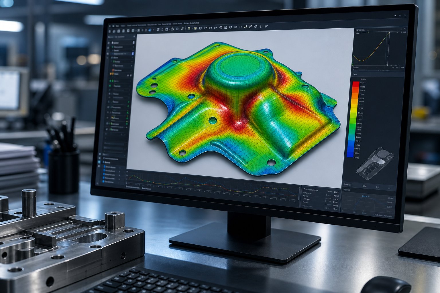
Where CAD handles the tooling geometry, finite element analysis handles the material behavior. Sheet metal forming simulation digitally replicates what happens to the blank as it contacts punches, flows over draw beads, and stretches into die cavities. The software meshes the blank into thousands of elements, assigns material properties (yield strength, strain-hardening curves, anisotropy values), and calculates deformation under the defined process conditions.
The output reveals exactly where problems will occur. Thinning maps highlight zones approaching material fracture limits. Compression indicators flag areas prone to wrinkling. Strain diagrams plotted against forming limit curves show how close each region sits to failure. For engineers working with advanced high-strength steels or aluminum alloys, these predictions are critical because such materials exhibit high springback magnitudes that make achieving dimensional accuracy a persistent challenge.
Springback prediction is where simulation delivers some of its greatest value to metal stamping tooling programs. The solver tracks the stress distribution through the entire forming sequence and calculates how much elastic recovery will occur once the press opens. Engineers then apply compensated die surfaces, overbending or reshaping the tooling geometry so that springback brings the part to its intended final shape. This compensation can even be automated within the software, generating modified tool surfaces ready for CAM programming.
From Virtual Validation to Physical Tryout
Simulation does not eliminate physical tryout. It dramatically reduces how many tryout loops you need. Research from Fraunhofer IWU demonstrates that incorporating elastic behavior models of both the die and the press machine into simulation produces virtual spotting patterns that closely match real-world results, enabling engineers to correct die surfaces during the design phase rather than through costly manual rework on the shop floor.
The real power emerges in the feedback loop. Physical tryout results, measured springback angles, actual thinning distributions, observed wrinkling locations, feed back into the simulation model as validation data. Where predictions matched reality, confidence grows. Where they diverged, the model is recalibrated: friction coefficients adjusted, material curves refined, boundary conditions corrected. Over successive projects, this iterative refinement builds a simulation environment whose predictions grow increasingly accurate for your specific press equipment, materials, and die construction methods.
Simulation-driven die design typically reduces physical tryout iterations by 50% or more, compressing development timelines from months to weeks and converting expensive press-floor problem-solving into low-cost virtual optimization.
This virtual-to-physical loop represents the current state of the art in die design methodology. But even the most sophisticated simulation cannot compensate for tooling that wears prematurely or fails under production loads. The material choices made for punches, die blocks, and wear components determine whether a validated design actually delivers its predicted lifespan on the press floor, a decision that hinges on matching tool steel properties to your specific production demands.
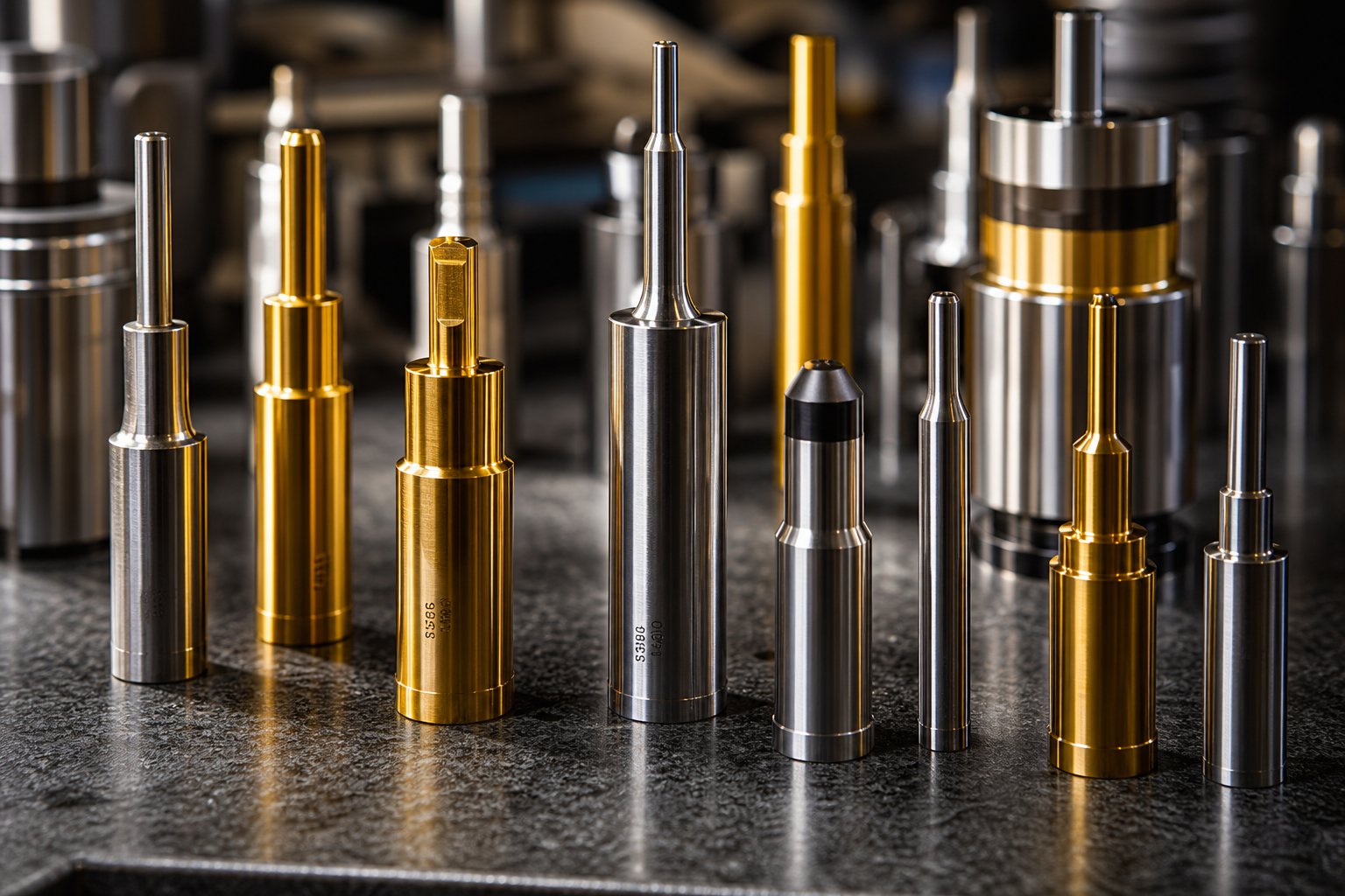
Die Material Selection and Coating Strategies
Your simulation predicted 500,000 hits before maintenance. Your strip layout is optimized, clearances are dialed in, and the station sequence is bulletproof. Yet the die fails at 80,000 strokes because the punch material could not handle the repeated impact loading of your high-strength stamped steel. Material selection is where design intent meets physical reality, and getting it wrong negates every upstream optimization you invested in.
The core challenge with steel stamping dies is that no single material excels at everything. Wear resistance, toughness, and compressive strength pull in competing directions. A grade that holds a razor edge for millions of cuts will shatter under heavy impact. A grade tough enough to absorb shock loading will dull quickly in abrasive conditions. The engineer's job is to identify which failure mode will appear first in each specific application, then select the grade that resists that dominant mechanism.
Tool Steel Grades for Punches, Die Blocks, and Wear Parts
Four tool steel families cover the vast majority of metal stamping die applications. Each occupies a distinct performance niche defined by its carbide content, alloy composition, and heat treatment response.
AISI D2 is the default choice when abrasive or adhesive wear limits tool life. Its high chromium and carbon content produces a dense carbide structure that allows cutting edges to retain geometry over long production runs. You will find D2 in blanking and piercing punches for high-volume automotive stamping die applications where edge sharpness directly governs burr height and part quality. The limitation is brittleness: once chipping or cracking appears during operation, D2 is no longer the right answer.
AISI A2 steps in when no single failure mode clearly dominates. It delivers a balanced combination of wear resistance and toughness, making it suitable for progressive die stations where punches experience both abrasion and moderate impact simultaneously. For production volumes under 100,000 parts or mixed-condition applications, A2 provides an economical middle ground without the brittleness risk of D2.
AISI S7 is the shock absorber of the tool steel family. When your die stations involve heavy-gauge steel sheet stamping or high-tonnage piercing operations, repeated impact stresses will fracture higher-carbide grades before wear ever becomes an issue. S7's superior toughness absorbs cyclic impact that would cause cracking in D2 or similar wear-focused grades. It trades some edge retention for the ability to survive punishing mechanical loads stroke after stroke.
AISI M2 occupies the intersection of wear resistance and compressive strength. Compared with D2, it provides better resistance to plastic deformation under load. Compared with S7, it maintains higher abrasion resistance. M2 is commonly applied to punches that must hold both edge geometry and dimensional accuracy under sustained compressive stress, a scenario typical in precision piercing of thick or high-strength materials.
Surface Coatings and Carbide Inserts for Extended Die Life
When base tool steel reaches its performance ceiling, surface engineering extends die life further. Two primary technologies serve this role in stamping: thin-film coatings and solid carbide inserts.
PVD coatings (Physical Vapor Deposition) apply thin layers of extremely hard compounds, typically 2-5 microns thick, at relatively low temperatures around 500 degrees Celsius. Because the process runs cool, it preserves the sharp cutting edges critical for precision piercing in a metal stamping die. PVD coatings like TiN, TiCN, and AlTiN reduce friction, resist adhesive wear, and maintain compressive stress in the coating layer that adds toughness against chipping in interrupted operations.
CVD coatings (Chemical Vapor Deposition) build thicker layers, 5-20 microns, through high-temperature chemical reactions. The result is superior heat resistance and adhesion, but the process slightly rounds cutting edges and leaves the coating in tensile stress. For stamping applications, CVD works best on forming components where heat buildup from sustained material contact is the primary degradation mechanism rather than edge sharpness.
Carbide inserts represent the most aggressive approach to wear resistance. Solid tungsten carbide tooling can extend die life by 500-1000% compared to traditional tool steels in applications involving abrasive workpiece materials or extreme production volumes. The tradeoff is brittleness: carbide inserts are limited to low-impact operations like fine blanking and shallow drawing where shock loading is minimal.
The Regrind vs. Coat Decision
Here is where cost-benefit thinking matters. Uncoated tool steel punches can be reground multiple times when edges dull, restoring performance at relatively low cost per cycle. Coated tooling runs longer between regrinds but costs more upfront, and some coatings complicate the regrind-and-recoat process. The decision hinges on your production math:
- Low-volume or prototype runs: Uncoated A2 or D2 with periodic regrinding is typically the most cost-effective path.
- High-volume production: PVD-coated punches reduce changeover frequency, and the extended run time between maintenance events often offsets the coating investment through reduced downtime.
- Abrasive materials (stainless, HSLA): Carbide inserts or heavy-duty coatings pay for themselves rapidly when uncoated tools degrade within thousands of strokes rather than tens of thousands.
Advanced coatings like TiN or DLC can extend die life by 30-50% by reducing friction and wear, particularly in stainless steel stamping. The key is matching the coating chemistry to your workpiece material and operation type rather than defaulting to whatever coating your supplier stocks.
Die Material Comparison by Properties and Application
| Material Category | Representative Grade | Relative Wear Resistance | Relative Toughness | Typical Applications |
|---|---|---|---|---|
| High-Carbon High-Chromium | D2 | High | Low to Moderate | High-volume blanking, piercing punches, die buttons for automotive stamping die programs |
| Air-Hardening (Balanced) | A2 | Moderate | Moderate | Progressive die stations with mixed wear and impact, medium-volume production |
| Shock-Resistant | S7 | Low to Moderate | High | Heavy-gauge piercing, forming punches, high-impact stations |
| High-Speed Steel | M2 | High | Moderate | Precision punches under high compressive load, thick material piercing |
| Cemented Carbide | Tungsten Carbide | Very High | Low | Fine blanking, high-volume abrasive material processing, wear inserts |
| PVD-Coated Tool Steel | D2 + TiCN/AlTiN | Very High (surface) | Base steel dependent | Extended-life piercing, stainless steel stamping, reduced-friction forming |
Navigating these material and coating decisions for every punch, die block, and wear component across a complex progressive die is one of the more nuanced challenges in tooling engineering. Each station may demand a different grade based on its specific loading profile, workpiece interaction, and target maintenance interval. Engineers who need support matching tool steel grades and coatings to specific production requirements can leverage custom die solutions from specialists like YICHEN, who engineer material selections for punches, die blocks, and wear components based on actual workpiece materials, production volumes, and target die life rather than one-size-fits-all defaults.
Material selection closes the loop on individual component design. But a stamping die project is not a collection of isolated decisions. Die type, clearance, station sequence, simulation validation, and material choices all interact as a system. Pulling these threads together into a coherent project workflow is what separates a functional die from one that delivers sustained production performance.
Putting These Fundamentals Into Practice
Individual design decisions are powerful. Combined into a disciplined workflow, they compound into dies and stamping systems that hit quality targets from the first production run rather than after months of costly tryout iterations. The difference between a project that goes smoothly and one that spirals into rework almost always traces back to whether the engineering team followed a structured decision sequence or jumped straight into CAD modeling without grounding their assumptions.
Engineering Decision Checklist for New Die Projects
Every metal stamping process shares the same fundamental decision path regardless of part complexity or production volume. When you start a new die stamping project, working through these steps in order prevents the kind of backtracking that blows schedules and budgets.
- Define part requirements completely. Gather the finished part drawing with full GD&T callouts, material specification, annual volume forecast, and target cost per piece. Identify functional datums, critical-to-quality dimensions, and any downstream assembly constraints that influence burr direction or tolerance priority.
- Select the die type. Match your part geometry, volume, and tolerance needs against progressive, compound, or transfer architectures. Let the part drive the decision rather than defaulting to what your shop ran last.
- Determine clearances per station. Calculate punch-to-die clearance as a percentage of material thickness for each cutting operation, referencing material-specific tooling data rather than a universal default. Account for burr direction requirements on every pierced and blanked feature.
- Sequence stations and optimize the strip layout. Establish pilots and carrier geometry first, sequence cuts before forms, progress from least to most severe deformation, balance forces across the strip width, and place blanking at the final station.
- Validate with simulation. Run FEA formability analysis to confirm material flow, check thinning against forming limit curves, predict springback magnitude, and apply compensation to die surfaces before releasing for manufacture.
- Select tool steel grades and coatings. Match each component's material to its dominant failure mode: wear-resistant grades for abrasive conditions, shock-resistant grades for impact loading, and coatings or carbide inserts where base steel reaches its performance ceiling.
- Release for build, then close the loop in tryout. Use physical tryout results to validate simulation predictions, refine friction and material models, and build institutional knowledge that improves accuracy on the next project.
Connecting Design Fundamentals to Production Success
Notice how each step in that checklist depends on the one before it. You cannot calculate clearances without knowing your material. You cannot sequence stations without knowing which operations your part requires. You cannot select tool steel without understanding the forces each station will experience. These fundamentals are not independent topics you study in isolation. They form a connected system where strength in one area amplifies every other, and weakness in one area undermines the rest.
Engineers who internalize this systems-level thinking spend less time firefighting on the press floor. Their metal parts stamping programs launch faster, hold tolerance longer between maintenance cycles, and consume less material per part. The payoff is not abstract. It shows up in reduced scrap rates, fewer unplanned die pulls, and stamping parts that pass inspection without sorting or rework.
For teams navigating complex projects where die structure, clearance optimization, material flow challenges, and component-level decisions intersect, working with an experienced tooling partner accelerates the path from concept to production-ready tooling. YICHEN's custom stamping die solutions connect tooling engineers to expertise across the full scope of these fundamentals, from initial die type selection through material and coating strategies, helping translate sound engineering methodology into dies that perform as designed from day one.
Stamping Die Design Fundamentals FAQ
1. What is the difference between progressive, compound, and transfer stamping dies?
Progressive dies feed a continuous strip through multiple stations, each performing a different operation, making them ideal for high-volume small parts. Compound dies perform two or more cutting operations simultaneously in one stroke, delivering superior concentricity for flat profiles like washers and laminations. Transfer dies separate individual blanks and move them between stations using mechanical arms, which suits large or deep-drawn parts like automotive body panels that cannot remain attached to a carrier strip.
2. How do you determine the correct punch-to-die clearance for stamping?
Clearance is calculated as a percentage of material thickness per side, varying by material type. Soft materials like aluminum typically use 10-15% per side, mild steel uses 10-12%, stainless steel requires 12-16%, and high-strength steels demand 18-20% or more. The correct value depends on material hardness, ductility, acceptable edge quality, and target tool life. Engineers should reference material-specific clearance charts from tooling suppliers rather than applying a single universal default across all operations.
3. What causes wrinkling, splitting, and springback in stamped parts?
Wrinkling occurs when blank holder pressure is insufficient and material flows too freely into the die cavity, causing compression buckles. Splitting happens when draw depth exceeds material ductility limits or punch radii are too tight, forcing localized thinning until fracture. Springback results from elastic recovery after bending, particularly in high-strength materials. Die designers counter these with draw beads for wrinkling, multi-stage draws for splitting, and overbending or coining for springback compensation.
4. Why does station sequencing matter in progressive die design?
Station sequencing determines whether a progressive die runs reliably or generates scrap. Pilot holes must be pierced first to establish positional datums for all subsequent operations. Carrier strip geometry follows to maintain strip rigidity. Cutting operations precede forming because holes punched into already-formed surfaces distort unpredictably. Forces must be balanced across stations to prevent strip misregistration. Blanking always occurs last since the part cannot be indexed once separated. Incorrect sequencing leads to cumulative tolerance drift, strip walking, and premature die wear.
5. How do you choose the right tool steel for stamping die components?
Selection depends on identifying the dominant failure mode for each component. D2 high-chromium steel suits high-volume blanking where abrasive wear limits life. A2 provides balanced wear resistance and toughness for mixed-condition progressive die stations. S7 absorbs heavy impact loading in thick-gauge piercing operations where D2 would crack. M2 high-speed steel handles high compressive loads while maintaining edge geometry. For extreme wear resistance, carbide inserts extend life 500-1000% over conventional steels. Partners like YICHEN (https://www.yichen-group.com/stamping-die/) help engineers match grades and coatings to specific production demands.


