


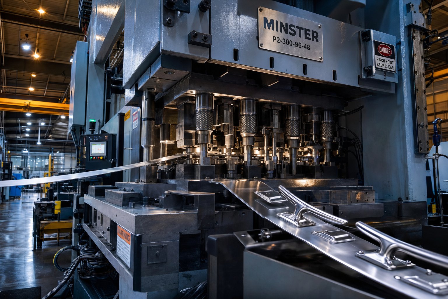
What Progressive Die Metal Stamping Means for Marine Hardware
Imagine feeding a continuous strip of corrosion-resistant stainless steel into a press and getting a finished deck cleat out the other end, shaped, pierced, and trimmed in under a second. That's progressive die metal stamping at work. It's the manufacturing backbone behind countless marine hardware components that need to survive salt spray, dynamic loads, and years of UV exposure without a single dimensional compromise.
Progressive die metal stamping is a metalworking process in which a strip of metal advances through a series of sequential die stations, each performing a specific operation such as blanking, piercing, bending, forming, or coining, to produce a finished part in a single continuous press cycle.
For marine hardware, this process isn't just efficient. It's essential. The alloys used at sea, think 316 stainless steel, naval brass, and marine-grade aluminum, demand tooling precision that compensates for their unique forming behaviors. And the parts themselves, from structural cleats to flush-mount hinges, must hold tight tolerances across production runs of thousands or millions.
How Progressive Die Stamping Works Station by Station
So what is a progressive die, exactly? Picture a single die set containing anywhere from 4 to 20 individual stations arranged in sequence. A coil of sheet metal feeds into the press, and with each stroke, the strip advances one station forward. The part stays attached to a carrier strip throughout the entire progression, which keeps it aligned and eliminates the need for manual handling between operations.
Each station performs one task: the first might punch pilot holes for alignment, the next blanks the outer profile, a third bends a flange, and so on. By the final station, the finished component is cut free from the carrier strip, ready for finishing or assembly. The progressive die stamping process explained in simple terms is this: one press stroke equals one completed part, with every feature formed in precise sequence.
Why Marine Hardware Demands This Level of Precision
Marine components aren't decorative. They're safety-critical. A railing stanchion base that varies by half a millimeter between units introduces a stress concentration that saltwater corrosion will find and exploit. A mounting bracket with inconsistent hole spacing won't align with through-bolted hull fittings.
Progressive die stamping delivers dimensional consistency across every single part because the process removes operator-dependent variation entirely. It also minimizes material handling, which reduces surface contamination on alloys where the passive oxide layer is the first line of corrosion defense. And because multiple operations happen within one die set, secondary machining steps are reduced or eliminated, keeping part cost predictable at scale.
This article covers the full intersection of progressive die stamping and marine hardware engineering, from material selection and die design through production economics and post-stamping finishing. The goal: equip marine hardware designers and procurement teams with the technical depth needed to leverage this process effectively. That conversation starts with a critical question, why choose progressive die stamping over CNC machining, casting, or single-hit methods for parts destined for saltwater service?
Why Progressive Die Stamping Outperforms Alternatives for Marine Parts
Marine hardware manufacturers have options. CNC machining can cut complex geometries from billet. Investment casting handles organic shapes well. Single-hit stamping works for simple flat blanks. So why do boat builders and marine accessory OEMs increasingly rely on progressive die metal stamping services for their production hardware? The answer comes down to three pillars that matter more at sea than in any other operating environment: repeatability, cost efficiency at volume, and forming consistency with corrosion-resistant alloys.
Repeatability and Safety in Marine Applications
Consider a stainless steel cleat mounted on a foredeck. It bears dynamic loads from docking lines in a corrosive saltwater environment, day after day, season after season. If dimensional variation creeps in between units, some cleats will carry stress concentrations at slightly different points, and crevice corrosion will exploit those inconsistencies.
Progressive die stamping vs CNC machining comes down to this: CNC relies on tool wear compensation and operator programming, introducing subtle part-to-part drift over long runs. Progressive die tooling, by contrast, produces each part through identical mechanical motions governed by hardened steel stations. There's no operator-dependent variation. Every cleat, hinge, and deck fitting emerges with the same dimensions as the first, whether you're pulling part number 100 or part number 100,000. For safety-critical marine components bearing dynamic loads, that kind of consistent quality and precision isn't a luxury. It's a structural requirement.
Cost Efficiency at Marine OEM Volumes
Progressive die tooling requires significant upfront investment. You're paying for multi-station die engineering, hardened tool steel, and precision grinding before a single production part ships. So where's the payoff?
It's in amortization. Once the die is built, each press stroke produces a finished part in seconds with minimal labor input. For boat builders running production quantities of brackets, latches, or mounting plates, those thousands or millions of identical parts spread the tooling cost thin. Per-part pricing drops dramatically compared to CNC machining, which charges machine time per unit regardless of volume. Single-hit stamping looks cheaper upfront, but it requires multiple dies and inter-operation handling for anything beyond a flat blank, adding hidden labor and quality risk. Progressive die stamping services consolidate everything into one continuous press cycle, and that consolidation is where marine OEMs find their margin.
Forming Consistency with Corrosion-Resistant Alloys
Here's where the comparison gets technical. Marine-grade alloys don't behave like mild steel under tooling pressure. 316 stainless steel work-hardens aggressively, meaning it gets stiffer as you form it. Naval brass has different springback characteristics that vary with grain direction. These materials push back unpredictably in single-station operations.
Progressive dies solve this by tuning each station to compensate for the material's behavior at that specific point in the forming sequence. A bending station can be designed with over-bending compensation of 3 to 5 degrees to counteract stainless steel springback, and because the strip moves through stations in a fixed sequence, that compensation is applied identically to every part. The result is dimensional accuracy within tight tolerances across the entire production run, even with alloys that would challenge less controlled forming methods.
These three advantages compound when you're producing hardware destined for saltwater. But repeatability and cost efficiency mean little if the wrong alloy enters the die in the first place. The next critical decision for marine hardware engineers is material selection, and each alloy family brings its own set of stampability challenges to the progressive die.
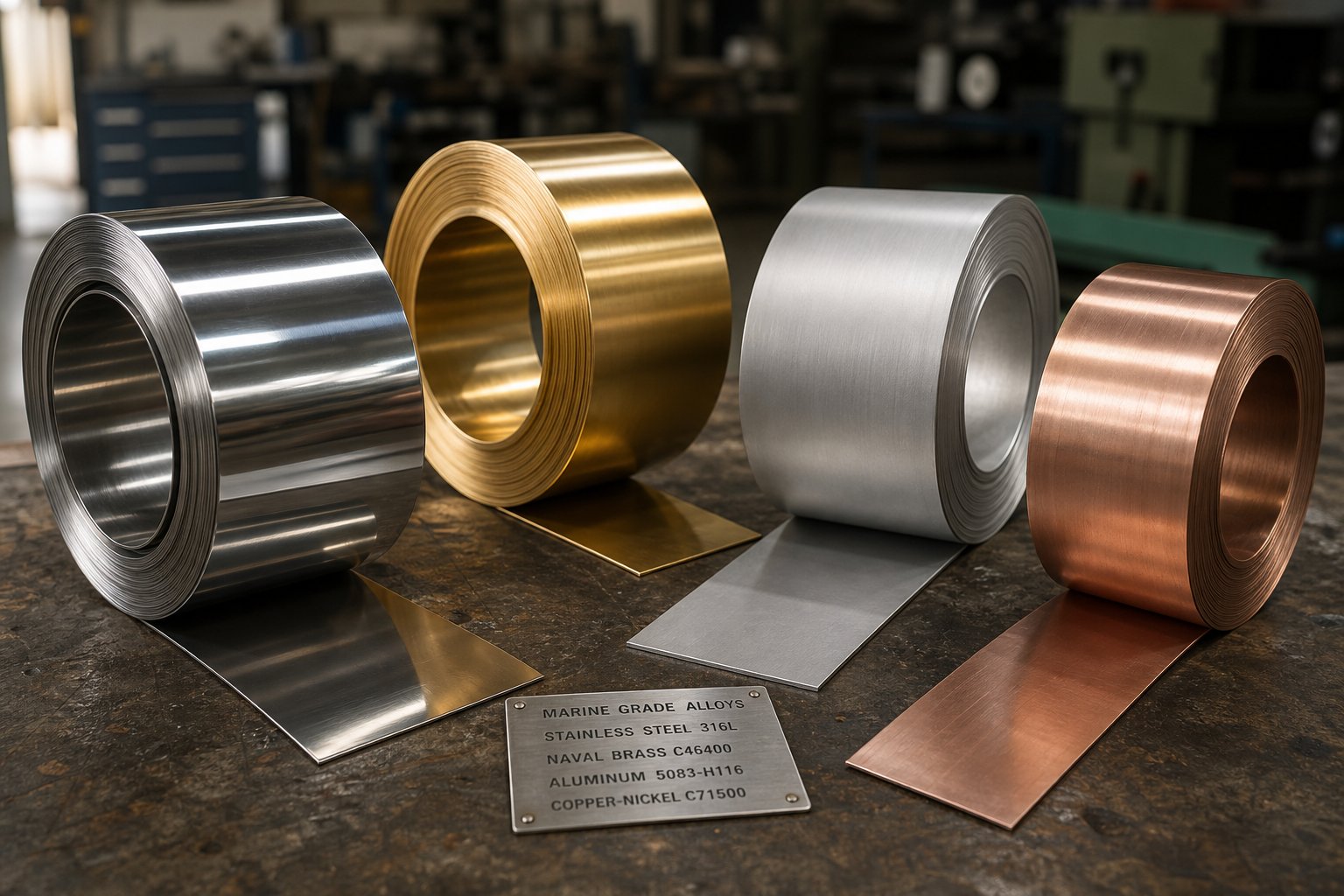
Marine-Grade Materials and Their Progressive Die Stampability
Every marine hardware program begins with the same question: which alloy can survive decades of saltwater exposure while still being formable at production speed? The answer depends on the application, but the stamping implications of that choice are where most design teams get tripped up. Marine-grade alloys behave very differently from mild steel under progressive die operations. Work-hardening rates spike, tonnage requirements jump, and springback throws off bend angles if the die isn't engineered for the specific material running through it.
Here's how the primary alloy families used in marine hardware perform when fed through a multi-station progressive die.
Stainless Steel 316 and 316L for Maximum Chloride Resistance
When engineers specify marine grade stainless steel stamping, they almost always mean 316 or its low-carbon variant 316L. The added molybdenum in these grades provides superior resistance to chloride-induced pitting and crevice corrosion, making them the default for any hardware in direct saltwater contact. But that corrosion resistance comes with real forming challenges.
Austenitic stainless steels like 316 exhibit aggressive work-hardening during deformation. As the metal passes through progressive die stations, each forming operation increases the material's hardness, meaning subsequent stations require exponentially higher tonnage to achieve the same deformation. A 2mm bracket that runs on a 100-ton press in mild steel can easily require 200 tons for the same geometry in stainless. That tonnage escalation dictates press selection, station spacing, and overall die architecture.
Springback is equally demanding. Stainless steel's high yield strength means the metal tries to return to its flat state after each bend. Tooling engineers typically machine punch-and-die angles to 93 degrees when holding a strict 90-degree tolerance, forcing the material to relax into specification. In a progressive strip, this compensation must be precise at every bending station, because any cumulative error compounds through the remaining progression.
Station spacing matters too. Because 316 work-hardens so rapidly, placing forming stations too close together in the strip can cause premature fracturing. Die designers often add idle stations between heavy forming operations, giving the strip structural breathing room and keeping the carrier intact through the full progression.
Galling presents another concern specific to stainless steel progressive stamping. The material's chromium oxide layer can be stripped away under high friction at the die radius, leading to cold-welding between the workpiece and tool steel. Mitigating this requires PVD-coated tooling (such as TiCN or AlTiN) and extreme-pressure lubricants formulated for austenitic grades. Without these measures, die maintenance intervals shrink dramatically.
Naval Brass and Bronze Alloys for Traditional Marine Fittings
Not every marine fitting demands stainless steel. Traditional boat hardware, decorative fittings, turnbuckles, and propeller shaft components have relied on copper-based alloys for over a century. Among these, C46400 naval brass stands out for its combination of saltwater corrosion resistance, moderate strength, and excellent formability.
From a steel progressive stamping comparison standpoint, naval brass is far more forgiving in the die. It work-hardens at a slower rate than austenitic stainless, requires substantially less press tonnage, and flows into complex forms without the same fracturing risk. Its natural galling resistance also means tooling wear is less aggressive, extending die maintenance intervals. For marine hardware programs producing decorative fittings, fasteners, or valve components, C46400 offers an appealing balance of formability and corrosion performance.
Bronze alloys, however, introduce more complexity. Phosphor bronze and aluminum bronze grades are harder and less ductile than naval brass, making tight-radius bends problematic. Progressive die stations forming bronze parts need generous bend radii, typically 1.5 to 2 times material thickness, to avoid edge cracking. Deep drawing operations with bronze also demand careful blank-holder pressure tuning to prevent wrinkling on flanges.
Marine-Grade Aluminum and Copper-Nickel Alloys
The push for lighter vessels and fuel efficiency has driven growing adoption of 5000-series marine-grade aluminum in hardware applications. Alloys like 5052 and 5083 contain magnesium and chromium for corrosion resistance, and they work well for stamped brackets, mounting plates, and lightweight deck fittings.
Progressive dies must accommodate aluminum's lower elongation limits compared to stainless steel. You'll notice that 5000-series alloys fracture sooner under aggressive drawing or stretching, so die designs favor shallower draw depths and wider bend radii. The upside: aluminum requires significantly less press tonnage, allowing faster stroke rates and higher throughput. Station spacing can be tighter since work-hardening is less severe. The trade-off is that aluminum's softer surface scratches more easily during strip advancement, requiring careful die polishing and lubricant selection.
Copper-nickel alloys, particularly 90/10 (C70600) and 70/30 (C71500), serve a specialized niche in seawater piping components, through-hull fittings, and heat exchanger hardware. These alloys offer outstanding resistance to biofouling and erosion-corrosion in flowing seawater. Their formability falls between naval brass and stainless steel, with moderate work-hardening and reasonable tonnage requirements. Progressive die operations with copper-nickel work best for shallow forms and blanking-heavy progressions rather than deep drawing.
| Alloy Family | Typical Marine Applications | Formability Rating | Corrosion Resistance Class | Progressive Die Considerations |
|---|---|---|---|---|
| 316/316L Stainless Steel | Cleats, hinges, railing bases, mounting brackets, deck fittings | Moderate | Excellent (chloride/pitting) | High tonnage, aggressive springback, requires PVD-coated tooling and EP lubricants, wider station spacing |
| C46400 Naval Brass | Decorative fittings, turnbuckles, fasteners, valve stems, propeller hardware | Excellent | Good (saltwater) | Lower tonnage, slower work-hardening, natural galling resistance, extended die life |
| Phosphor/Aluminum Bronze | Bearings, bushings, heavy-duty marine fasteners | Fair | Good to Excellent | Requires generous bend radii (1.5-2T), limited deep draw capability, careful blank-holder tuning |
| 5000-Series Aluminum (5052, 5083) | Lightweight brackets, mounting plates, deck hardware, trim components | Good | Good (atmospheric/splash zone) | Lower tonnage, faster stroke rates, limited elongation restricts draw depth, scratch-prone surface |
| Copper-Nickel 90/10, 70/30 | Through-hull fittings, pipe flanges, seawater system components | Moderate to Good | Excellent (flowing seawater, biofouling) | Moderate tonnage, suited for blanking-heavy progressions, limited deep draw suitability |
Galvanic Compatibility in Assembled Marine Hardware
Selecting the right alloy for stampability is only half the equation. When stamped parts from different alloy families contact each other in an assembled marine fitting, galvanic corrosion becomes a real threat. Aluminum is highly active on the galvanic scale and will corrode rapidly when in direct contact with copper-based alloys or stainless steel in a saltwater electrolyte. Stainless steel and bronze are closer together galvanically but still require isolation in critical applications.
For marine hardware engineers specifying progressive die stamped components, this means considering the full assembly context during material selection. If a stamped aluminum bracket mounts against a stainless steel through-hull fitting, an insulating barrier or sacrificial anode strategy must be designed into the installation. The die designer doesn't control this, but the hardware designer must account for it before locking in the alloy for stamping.
Material choice shapes everything downstream in a progressive die program, from the tonnage of the press to the coating on the tooling to the geometry of every station. And those station geometries, in turn, define which marine hardware categories can be produced in a progressive die and which demand alternative methods.
Marine Hardware Components Produced by Progressive Die Stamping
Which marine parts actually come off a progressive die? The answer covers more of a vessel than most people realize. From the structural hardware holding railing systems together to the tiny clip fasteners securing wire looms behind cabin panels, progressive die stamping touches nearly every system on a boat. The key differentiator is volume and geometric complexity. If a marine metal stamping part needs multiple features formed in sequence and ships in quantities above a few thousand annually, it's a candidate for progressive tooling.
Here's how the major marine hardware categories break down by stamping complexity and die requirements.
Structural Marine Hardware and Load-Bearing Fittings
Think about the hardware that keeps people safe on deck: cleats that absorb docking shock loads, chocks that guide mooring lines without chafing, fairleads that redirect running rigging, railing stanchion bases bolted through the deck, and the countless mounting brackets tying it all together. These parts share a common trait. They bear dynamic loads in a corrosive environment, so they need both mechanical strength and dimensional precision across every unit produced.
From a stamping perspective, structural marine fittings combine blanking and deep drawing with heavier material gauges, typically 2mm to 4mm stainless steel. A cleat horn, for example, requires progressive forming across multiple stations to develop its 3D profile from a flat strip without thinning the material below safe load-bearing thresholds. Stanchion bases demand blanked mounting holes with tight position tolerances since they must align with pre-drilled deck patterns across different boat models.
The challenge with this category is press tonnage. Blanking a 3mm 316 stainless profile requires substantially more force per linear inch of cut than typical sheet metal work, and adding deep drawing stations to the same die compounds that load requirement. Die designers balance station forces carefully to avoid overloading the press at any single stroke position.
Closure and Articulation Hardware
Open any hatch, locker door, or engine compartment on a production boat and you'll find hinges, latches, hasps, and catches, all of which cycle thousands of times over a vessel's service life while resisting salt spray corrosion. Marine hardware fittings stamping for this category is where progressive die technology shows its most elegant efficiency.
Imagine a stainless steel hinge leaf. It needs a flat mounting surface with countersunk screw holes, a knuckle barrel rolled along one edge, and perhaps a detent feature pressed into the leaf for hold-open friction. In a conventional manufacturing approach, you'd blank the flat, machine the holes, then roll the knuckle in a separate forming operation. Three setups, three handling steps, three opportunities for dimensional drift.
A progressive die integrates all of these operations into the strip progression. Early stations blank and pierce the mounting holes. Mid-progression stations progressively curl the knuckle barrel, rolling it in two or three incremental steps to avoid cracking the outer fiber of the stainless. Final stations coin the detent feature and sever the finished hinge leaf from the carrier strip. The result is a complete hinge component in one press cycle, with the knuckle geometry identical on every single piece.
Porthole frames and portlight bezels represent another articulation-adjacent category. These require annular blanking followed by shallow drawing or flanging to create the lip that seats against gasket material. Progressive dies handle this geometry efficiently when the frame diameter stays within the press bed dimensions.
Deck Fittings and Fastening Components
This category represents the highest volume of progressive die stamped brackets and components in the marine industry. Deck fittings and fasteners are used everywhere on a vessel, from hull structural systems to interior cabinetry to electrical panel mounting. Their common thread is relatively simpler geometry produced in very high quantities, making them ideal candidates for high-speed progressive die runs.
Typical marine deck fitting and fastener families include:
- Pad eyes - blanking, piercing, and drawing to form the attachment loop; often coined for load-bearing surface finish
- Backing plates - blanking and piercing with multiple hole patterns; minimal forming, high dimensional accuracy required
- Through-hull flanges - annular blanking, drawing to create collar depth, piercing for bolt circles
- Clip fasteners and spring clips - blanking, bending, and hemming to create spring tension in the finished form
- Cable and pipe mounting brackets - blanking, piercing, compound bending to create U-channel or saddle profiles
- Electrical mounting plates - blanking, piercing arrays, light embossing for stiffening ribs
- Cabinet and joinery brackets - blanking, multi-axis bending, coining for decorative edges
Progressive die stamped brackets dominate marine production volumes because a single vessel can require hundreds of bracket variants across its hull systems, interior joinery, and electrical infrastructure. Even when each variant has its own dedicated die, the per-part economics at marine OEM volumes make progressive tooling the clear choice over fabricated or machined alternatives.
What makes these fastening components particularly well-suited to progressive stamping is their combination of repetitive geometry and critical hole-position accuracy. A backing plate with bolt holes 0.3mm off-pattern won't align with the deck hardware it supports. Progressive dies hold that positional accuracy stroke after stroke because the pilot pins re-register the strip at every station, eliminating cumulative positioning error.
Each of these component categories places different demands on the die itself. Structural hardware pushes tonnage limits. Articulation hardware requires creative station sequencing. Deck fittings demand speed and positional precision. Those varying demands mean the die design philosophy must shift depending on the end-use environment, and marine service introduces a set of design constraints that most general stamping dies never encounter.
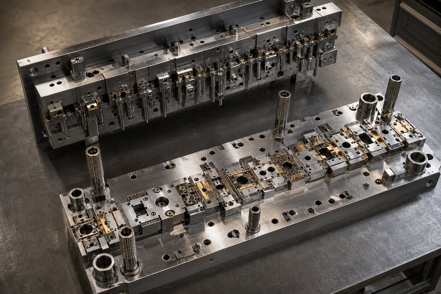
Die Design Considerations Unique to Marine Environments
A progressive die built for automotive brackets or electronic enclosures won't cut it for marine hardware. The tooling might look similar on paper, same multi-station layout, same blanking and forming operations, but the design philosophy behind every station must account for what happens after the part leaves the press. Salt spray, standing water, cyclic loading from wave action, and aesthetic expectations from boat owners all dictate specific die engineering choices that general stamping shops rarely encounter.
Progressive die tooling design for marine hardware isn't about adding complexity for its own sake. It's about preventing corrosion initiation, controlling surface quality at the source, and managing the heavier gauges that marine applications demand. Each of those requirements reshapes how die stations are configured, spaced, and maintained.
Radius and Edge Design for Corrosion Prevention
Here's a scenario that plays out on docks everywhere: a stamped stainless fitting develops rust streaks within two seasons, not because the alloy was wrong, but because the die left a sharp internal corner or a burr-prone sheared edge that became a crevice corrosion initiation site. In saltwater, the mechanism is aggressive. Chloride ions migrate into narrow crevices, the local pH drops as oxygen is consumed, and once the passive chromium oxide layer is breached, the attack becomes self-sustaining.
For progressive carbide stamping dies serving marine programs, this means every cut edge and formed radius must be designed to deny corrosion a foothold. Specifically:
- Generous internal radii - Where general stamping might accept a bend radius equal to material thickness (1T), marine die designs often specify 1.5T to 2T minimum. This eliminates the tight crevice geometry that traps stagnant electrolyte at bend transitions.
- Coining stations for edge treatment - Rather than leaving sheared edges in their as-blanked state (which always carries a fracture zone and potential micro-burrs), marine die progressions include dedicated coining or ironing stations that compress the cut edge, closing micro-cracks and smoothing the burr side.
- Controlled die clearance - Tighter punch-to-die clearances (typically 5-8% of material thickness for stainless) produce a cleaner shear zone with less fracture, reducing the rough edge area where corrosion can initiate.
The principle from corrosion engineering is straightforward: keep junction points as wide open as possible and avoid designed-in crevices. In progressive die terms, that translates to station sequences that actively remove the geometric vulnerabilities other industries tolerate.
Surface Finish Requirements in Die Design
You'll notice that marine hardware on a production boat often carries a mirror polish or fine directional brush finish. This isn't just cosmetic. Smooth surfaces resist salt crystal adhesion better than rough ones, shed water faster, and are easier to maintain over a vessel's service life. The critical point for stamping dies manufacturing is that the part surface finish is largely determined by the die surface itself. Every imperfection in the die face transfers directly to the stamped component.
For marine-grade progressive dies, this means working with polished carbide inserts at forming and coining stations. Tungsten carbide tooling components can be precision polished to surface finishes as fine as Ra 0.005, using diamond paste progression techniques that move from rough grinding through metallographic sandpaper stages to final mirror polish. At those finish levels, the stamped part emerges with a surface quality that requires minimal post-stamping polishing.
Die maintenance intervals tighten considerably for marine work. Where an automotive stamping die might run 500,000 strokes between re-polishing, marine hardware dies producing mirror-finish stainless parts often require surface maintenance every 50,000 to 100,000 strokes, depending on material and lubrication strategy. Any scoring or galling on the die face instantly shows up as a defect line on the finished marine fitting.
Polished die surfaces also reduce friction during strip advancement, which matters when running work-hardening alloys like 316 stainless. Lower friction means less heat generation at the die-workpiece interface, less risk of galling, and more consistent material flow into forming stations. It's a functional advantage disguised as an aesthetic requirement.
Material Thickness and Station Load Balancing
Marine hardware lives in a different weight class than consumer electronics stampings or thin-gauge automotive panels. Deck cleats, stanchion bases, and structural brackets routinely call for 1.5mm to 4mm stainless steel, sometimes thicker for heavy-duty commercial vessel fittings. That heavier gauge fundamentally changes the die engineering equation.
The tonnage calculation for each station follows a direct relationship: perimeter multiplied by material thickness multiplied by shear strength gives the blanking force, and forming operations add further load based on ultimate tensile strength and deformation geometry. When you double the material thickness, you roughly double the required tonnage at every cutting and forming station in the progression. A 12-station die forming 3mm 316 stainless can easily demand 200 to 400 tons of total press capacity, compared to 60 to 80 tons for the same geometry in 1mm mild steel.
This tonnage increase creates three downstream design challenges:
- Strip advancement force - Heavier strip stock resists feeding. Pilot pins must engage positively at each station, and feed mechanisms need higher grip force to advance the thicker material accurately. Die designers often specify larger pilot diameters and deeper engagement depths for marine gauges.
- Station spacing - Thicker materials need more room between stations to prevent strip distortion from adjacent forming loads. The carrier strip connecting stations must be wide enough to maintain structural integrity under the combined lateral forces of all active stations.
- Press deflection management - The total die tonnage must be balanced across the press bed to prevent uneven ram deflection. For marine dies with heavy loads concentrated at a few forming stations, designers reposition the die's centerline relative to the press centerline to equalize the load distribution.
One die feature uniquely relevant to marine hardware is drain hole piercing. Installed marine fittings often trap standing water in pockets or recesses, accelerating corrosion and promoting biological growth. Small weep holes, typically 3mm to 5mm diameter, allow water to drain freely from these areas. In a progressive die, adding a drain hole piercing station is trivial. It's just one more punch in the progression. But specifying the correct hole diameter, position, and edge quality at the die design stage prevents a corrosion problem that would otherwise require post-installation drilling, a far more expensive and less precise solution.
These marine-specific die design constraints, generous radii, polished surfaces, heavier gauge accommodation, and integrated drainage features, shape the tooling before a single part runs. They also influence which stamping operations are sequenced into the progression, and how those operations map to the specific geometries that marine parts require.
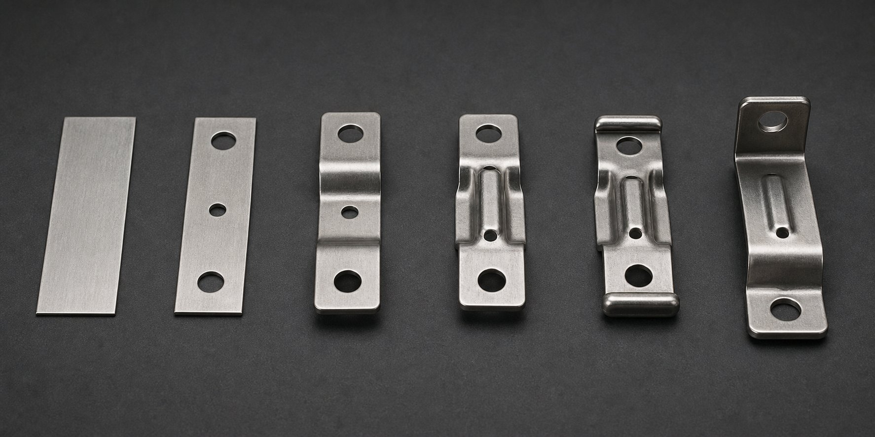
Key Stamping Operations Matched to Marine Part Geometries
Generic stamping guides list operations like blanking, piercing, and bending as if they exist in a vacuum. But the geometry of a marine rod holder demands very different progressive die forming operations than, say, a flat electrical terminal. Every operation in the progression must be mapped to a specific functional requirement of the finished marine component: structural stiffness, water drainage, mounting precision, or load distribution. That mapping is what separates metal stamping for marine precision parts from commodity stamping work.
Here's how the core stamping operations translate to real marine hardware geometries, and why the sequence matters as much as the individual operations themselves.
Forming and Drawing Operations for Marine Geometry
Marine hardware spans a wide range of three-dimensional shapes, from shallow stiffening features on flat brackets to fully enclosed cup forms in flush-mount fittings. Progressive die forming operations handle this spectrum by distributing the total deformation across multiple stations, each contributing incremental shape change without overstressing the material.
Deep drawing is the workhorse operation for cup-shaped marine fittings. Rod holders, recessed flush pulls, and cable pass-throughs all require the metal to flow from a flat blank into a cylindrical or tapered pocket. As noted in deep drawing process research, when the drawing depth exceeds roughly half the part diameter, multiple progressive draw stations become necessary to prevent tearing. For marine rod holders in 316 stainless, this typically means three to four incremental draw stations with inter-stage annealing consideration, because the material work-hardens between each draw reduction.
Shallow drawing serves a different marine purpose entirely. Flat structural brackets gain significant stiffness from embossed ribs or shallow drawn channels running across their surface. A 1mm-deep rib pressed into a 2mm stainless bracket can increase bending resistance by 30% or more without adding material weight. Progressive dies integrate these stiffening features as single-station emboss operations positioned after the primary blanking and piercing stages.
Complex 3D shapes like cleat horns push progressive forming to its limits. The horn profile curves upward and outward from the base in a compound geometry that can't be achieved in a single forming stroke. Instead, progressive die stampings develop the horn shape across three or four stations: an initial shallow form sets the base curvature, a second station deepens the profile, a third refines the tip geometry, and a final station coins the contact surface where dock lines will bear. Each station picks up where the last one stopped, with the carrier strip maintaining alignment throughout.
Blanking and Piercing Configurations for Marine Layouts
Blanking cuts the outer profile of the marine part from the strip. Piercing punches internal features like mounting holes, drain slots, and lightening cutouts. Both operations seem straightforward, but marine hardware introduces two complicating factors: expensive alloy coils and multi-hole mounting patterns that demand absolute positional accuracy.
Nesting strategy directly impacts material cost. Marine-grade 316 stainless coil stock costs significantly more per pound than mild steel, so every percentage point of material utilization matters. Die designers use advanced nesting algorithms that rotate and mirror part profiles within the strip to minimize the web width between parts. The target is reducing web spacing down to approximately 1.2 times the material thickness where structurally feasible, recovering material that would otherwise become expensive scrap. For symmetrical marine parts like backing plates or round flanges, common-line cutting between adjacent parts in the strip can push material utilization above 85%.
Piercing patterns for marine mounting flanges require tighter positional control than most industrial stamping. A through-hull flange with a six-bolt circle must place every hole within 0.05mm of true position so that it mates with standardized bolt patterns across different vessel manufacturers. Progressive dies achieve this through pilot pin registration at every station. The pilot holes, punched at the very first station, become the datum reference that every subsequent piercing and forming operation indexes from. Cumulative error is physically impossible because the strip re-registers against hardened pilot pins before each press stroke.
For parts requiring both large blanked profiles and fine pierced details, station sequencing follows a deliberate logic: pierce small features first while the strip is still flat and fully supported, then perform larger blanking cuts and forming operations that could distort the surrounding material. This approach preserves hole accuracy in the finished marine component.
Bending and Hemming for Structural Integrity
Bending transforms flat blanked profiles into three-dimensional structural shapes. Hemming folds an edge back onto itself to double the material thickness at critical stress points. Both operations are central to marine hardware where strength-to-weight ratio matters and bolted assemblies must resist cyclic fatigue from wave action.
Hemmed edges are particularly valuable in marine applications. As sheet metal hemming principles describe, folding an edge back onto itself reinforces it while eliminating sharp exposed surfaces. On a marine railing bracket, a hemmed top edge doubles the effective material thickness at the point of highest bending stress without requiring a thicker starting gauge. It also removes the sharp sheared edge that would otherwise become a corrosion initiation site and a safety hazard on deck hardware. Progressive dies form hems in two stages: a pre-bend station folds the edge to approximately 145 degrees, then a closing station flattens it against the parent material.
Compound bends create box-section profiles that deliver exceptional stiffness from thin sheet stock. A flat-blanked strip bent into a U-channel and then hemmed along the open edges produces a closed rectangular section with four material thicknesses at each corner. Marine railing brackets and structural supports use this technique to achieve the rigidity of a much heavier solid section while keeping weight manageable on deck-mounted hardware.
Understanding how each operation serves a specific marine function makes it possible to sequence an entire progression with purpose. Consider a typical marine mounting bracket requiring structural stiffness, precise mounting holes, corrosion-resistant edges, and a drain feature. Here's how an 8-station progressive die builds that part from a flat strip:
- Station 1: Pilot pierce - Punches precision pilot holes that register the strip at every subsequent station, establishing the datum for all dimensional features.
- Station 2: Notch - Removes material from the strip edges to define the bracket's outer profile boundaries and create clearance for upcoming bends.
- Station 3: First bend - Forms the primary structural flange at 90 degrees with over-bend compensation for stainless steel springback, creating the bracket's vertical mounting face.
- Station 4: Second bend - Forms the secondary return flange that provides box-section stiffness and creates the horizontal mounting surface.
- Station 5: Emboss - Presses stiffening ribs into the flat face of the bracket, increasing bending resistance without additional material or weight.
- Station 6: Drain hole pierce - Punches small weep holes (3-5mm) in pocketed areas that would otherwise trap standing water and accelerate crevice corrosion on installed hardware.
- Station 7: Hem - Folds exposed edges back onto themselves in a two-step closure, doubling edge thickness at stress points and eliminating sharp sheared surfaces.
- Station 8: Cutoff - Severs the finished bracket from the carrier strip with a clean shear, producing the completed part ready for finishing operations.
Each station exists for a reason tied directly to the bracket's marine service life. The emboss prevents flex-induced fatigue cracking. The drain holes stop corrosion from trapped saltwater. The hem reinforces the edges that boat owners will grab during hardware inspection. Nothing in this progression is arbitrary.
The cumulative effect of matching operations to marine requirements is a part that leaves the press needing minimal secondary work. But "minimal" doesn't mean "none." The economics of how many parts justify this level of die engineering, and when simpler methods make more financial sense, determines which marine hardware programs belong in progressive tooling and which don't.
Production Volume Economics for Marine Hardware Manufacturers
A progressive die that produces flawless marine brackets at 200 strokes per minute is worthless if you only need 500 parts. The tooling investment only makes sense when production volume is high enough to amortize that upfront cost into a negligible fraction of each finished piece. For marine hardware programs, understanding where that break-even point falls, and what hidden costs disappear once you cross it, separates profitable production decisions from expensive mistakes.
Volume Thresholds Where Progressive Dies Become Cost-Effective
Progressive die tooling represents a significant capital commitment. Depending on part complexity, number of stations, and material type, tooling costs from progressive die manufacturers typically range from $10,000 for simpler tools to $350,000 for complex multi-station dies. Marine hardware compounds this because corrosion-resistant alloys like 316 stainless accelerate tooling wear, often requiring carbide inserts and specialized coatings that push die cost toward the higher end of that range.
So when does the math work? The progressive die stamping cost per part drops dramatically as volume increases because tooling is a fixed one-time expense spread across every unit produced. A $50,000 die adds $10 per piece at 5,000 parts but only $0.10 at 500,000 parts. Industry benchmarks suggest progressive stamping becomes economically viable starting around 50,000 to 100,000 units annually for parts with moderate complexity. Simpler marine hardware like flat backing plates or clip fasteners can justify tooling at lower volumes, sometimes 25,000 to 30,000 pieces, because fewer die stations mean lower upfront cost.
Compare that to CNC machining, which carries near-zero tooling cost but charges machine time on every single unit. At low volumes, CNC wins. But its cost curve is linear: the 50,000th part costs exactly the same as the first. Progressive stamping's curve is the opposite. After the initial tooling spike, marginal cost per part approaches just raw material and press time. For marine OEMs running standardized hardware across production boat lines, that crossover point arrives quickly.
Total Cost of Ownership Beyond Per-Part Price
Focusing only on piece price misses where progressive die stamping delivers its deepest savings for marine programs. The real economic advantage compounds across several factors that rarely appear on a single line item:
- Reduced secondary operations - A well-designed progression integrates bending, hemming, embossing, and drain hole piercing into one press cycle. Each operation eliminated from a separate downstream setup removes labor, handling, and queue time from the production flow.
- Lower scrap rates with optimized nesting - Progressive strip layouts engineered for expensive marine alloy coils maximize material utilization, recovering cost on every coil run compared to less efficient fabrication methods.
- Elimination of inter-operation handling - Parts stay on the carrier strip from first station to last. No bins of work-in-process sitting between machines. No manual loading into secondary fixtures. Less handling means fewer surface scratches on alloys where finish quality matters.
- Consistent quality reducing inspection burden - When every part is dimensionally identical, statistical process control becomes straightforward. First-article approval plus periodic SPC checks replace the 100% inspection that fabricated or manually formed marine parts often require.
These savings compound with volume. A marine bracket program running 200,000 units annually might save 30 seconds of secondary handling per part. That's 1,667 labor hours recovered, enough to justify the die investment on handling reduction alone.
| Volume Tier | Production Method | Relative Tooling Cost | Per-Part Cost Trend | Typical Lead Time |
|---|---|---|---|---|
| Prototype (1-100 units) | CNC machining or laser cutting | Very low to none | High (fixed per unit) | Days to 2 weeks |
| Low-volume (100-10,000 units) | CNC machining, turret punching, or single-hit stamping | Low to moderate | Moderate (linear with volume) | 2-4 weeks |
| Mid-volume (10,000-100,000 units) | Progressive die stamping or transfer stamping | High (amortized across run) | Low (drops sharply with volume) | 12-20 weeks for tooling, then days per production run |
| High-volume (100,000+ units) | Progressive die stamping | High (negligible per part at scale) | Very low (material + press time) | 12-20 weeks for tooling, continuous production thereafter |
The critical takeaway for marine hardware manufacturers: progressive die economics reward commitment. The longer the production program runs and the more units it produces, the more that initial tooling investment fades into insignificance against per-part savings. Working with an experienced progressive die manufacturer like YICHEN early in the design phase helps production engineers evaluate these volume economics before committing capital, ensuring the die investment aligns with projected production runs and that multi-station forming requirements are optimized for the target marine hardware volumes.
Of course, a part that costs pennies to stamp but fails within two seasons of saltwater exposure delivers negative value. The economics only hold when the stamped component survives its service environment. That durability depends heavily on what happens after the part leaves the press: the post-stamping finishing processes that transform a near-net-shape stamping into a marine-grade component capable of passing years of salt spray exposure.
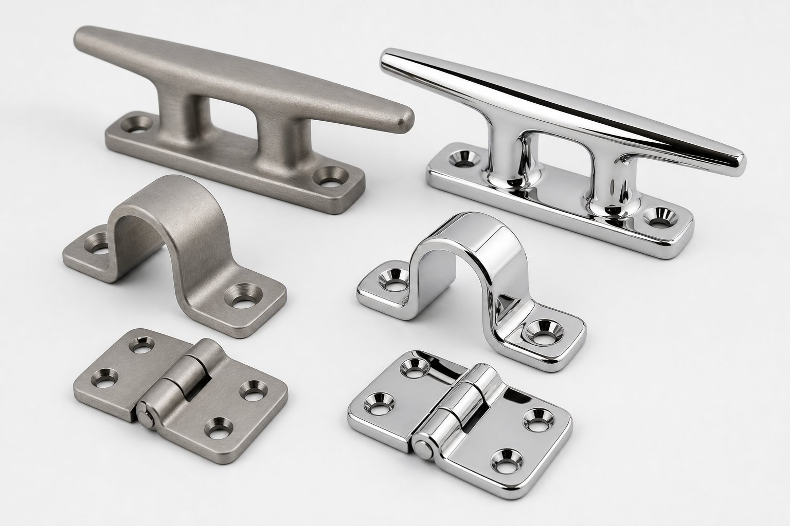
Post-Stamping Finishing Processes for Saltwater Durability
A progressive die delivers a dimensionally complete part, but dimensional completeness isn't the same as marine readiness. The stamping process introduces surface conditions that saltwater will exploit: free iron transferred from tooling contact, micro-burrs at sheared edges, and residual forming stresses that compromise the passive oxide layer. Marine hardware surface finishing after stamping isn't cosmetic polish work. It's the difference between a fitting that lasts fifteen years and one that shows rust staining within two seasons.
The finishing strategy depends on the base alloy, the severity of the marine environment, and the visual expectations of the end user. Stainless parts need their passive layer restored. Aluminum parts need barrier protection. And every specification must be communicated clearly enough that your progressive die stampings suppliers and finishing vendors deliver consistent results across production runs.
Passivation and Electropolishing for Stainless Marine Parts
Every stainless steel part that passes through a progressive die picks up free iron contamination. It's unavoidable. The tool steel punches, forming inserts, and even the press bed transfer microscopic iron particles onto the workpiece surface during blanking, bending, and coining operations. Those iron deposits become anodic sites where corrosion preferentially initiates in chloride-rich environments. Left untreated, a 316 stainless cleat will develop tea-colored rust streaks, not from the base material corroding, but from embedded iron particles oxidizing on its surface.
Passivation solves this. The process is straightforward: immerse the stamped part in a citric acid or nitric acid bath that dissolves free iron without attacking the base stainless steel. What remains is a surface with a higher chromium-to-iron ratio than the underlying alloy, promoting the formation of a dense, uniform chromium oxide layer. For metal stamping for marine components in 304 or 316 grades, passivation is the required minimum post-stamping treatment, not an optional upgrade. Any stamped stainless marine hardware shipped without passivation is, functionally, unfinished.
Electropolishing goes further. This electrochemical process removes 0.0001 to 0.001 inches of surface metal by making the part the anode in an electrolytic bath. Metal dissolves preferentially from micro-peaks and high points, smoothing the surface and removing the contaminated layer entirely. The result is a part that's geometrically smoother, metallurgically cleaner, and richer in chromium at the surface than either an unfinished or passivated part. For premium marine fittings, think helm hardware, visible T-top components, or anything in continuous saltwater contact, electropolishing delivers both maximum corrosion resistance and a bright, consistent appearance that passivation alone cannot achieve.
When should you specify one versus the other? Consider these factors:
| Factor | Passivation | Electropolishing |
|---|---|---|
| Process type | Chemical treatment (acid bath) | Electrochemical metal removal |
| What it removes | Surface contaminants only, no base metal | 0.0001-0.001 in. of base metal plus contaminants |
| Surface finish result | Passive layer restored; appearance unchanged | Smoother, brighter surface; enhanced passive layer |
| Corrosion resistance gain | Significant vs. unpassivated surface | Higher than passivation alone |
| Cost impact | Low to moderate | Moderate to high |
| Best for | Standard marine stainless hardware (majority of parts) | Premium exposed hardware, complex geometries, maximum saltwater performance |
One important caveat: neither process compensates for specifying the wrong stainless grade. Electropolished 304 in direct saltwater service will still underperform properly passivated 316, because surface treatment enhances what the base alloy provides rather than replacing the chloride resistance that molybdenum delivers.
Coating Systems for Non-Stainless Marine Hardware
Not every stamped marine part is stainless steel. Aluminum brackets, carbon steel fasteners, and mild steel structural components all require barrier coatings to survive saltwater exposure. The coating system must bond reliably to the stamped surface, tolerate the thermal cycling and UV exposure of marine environments, and deliver enough salt spray resistance for the intended service life.
Powder coating is the dominant choice for stamped steel and aluminum marine hardware. The electrostatically applied dry powder cures at 350-400 degrees Fahrenheit into a continuous polymer film typically 2-4 mil (50-100 micrometers) thick. Properly applied over pretreated steel, powder coating achieves 1,000 or more hours of salt spray resistance per ASTM B117. It's available in any RAL color, resists chipping and UV degradation better than wet paint, and produces no VOC emissions during application. For stamped marine brackets and mounting plates where appearance matters but full stainless cost isn't justified, powder coating over carbon steel offers an excellent performance-to-cost ratio.
Anodizing is the standard finishing treatment for stamped aluminum marine fittings. The electrochemical process grows a hard aluminum oxide layer on the part surface, significantly improving both corrosion resistance and surface hardness. Type II anodizing (0.3-1.0 mil thickness) suits most marine aluminum hardware and accepts dye coloring. Type III hardcoat anodizing (1.0-3.0 mil) provides superior wear and corrosion performance for high-abuse applications like cleat inserts or track fittings. For progressive die stamped aluminum parts, be aware that anodizing adds dimensional thickness. Type III grows approximately 50% outward, so features with tight tolerances may need to be stamped slightly undersize to hit final dimension after coating.
Zinc-nickel plating serves the marine fastener market. Stamped carbon steel clip fasteners, spring nuts, and cage nuts destined for bilge or engine compartment use benefit from zinc-nickel's combination of sacrificial protection and moderate salt spray resistance. Standard zinc plating per ASTM B633 with chromate conversion provides 96 to 240 hours of salt spray protection depending on thickness and post-treatment, while zinc-nickel alloy plating pushes that range significantly higher for fasteners in more aggressive marine zones.
Specifying Finish Requirements to Your Stamping Vendor
Here's where many marine hardware programs encounter friction: the engineering team knows the part needs "corrosion protection" but communicates that requirement in vague terms that leave the finishing vendor guessing. A specification that reads "passivate after stamping" tells the vendor nothing about the acid chemistry, immersion time, acceptance criteria, or performance expectation. The result is inconsistency between production lots and, eventually, field failures.
Marine hardware designers should communicate finish requirements using quantifiable parameters tied to recognized test standards. ASTM B117 defines the apparatus, salt solution concentration (5% NaCl), chamber temperature (35 degrees Celsius), and fog density for neutral salt spray testing, providing the universal framework that product-specific corrosion requirements build upon. When you specify "minimum 500 hours ASTM B117 with no red rust," every finishing vendor in the supply chain understands exactly what's expected and how it will be verified.
A complete finish specification package for marine stamped components should include:
- Base material condition - Specify whether the part arrives at finishing in the as-stamped state, tumble-deburred, or pre-cleaned. Surface contamination from stamping lubricants affects coating adhesion.
- Surface preparation method - Define the cleaning and pre-treatment process: alkaline wash, phosphate conversion coating, chromate pretreatment, or mechanical abrasion (bead blast grit and mesh specification).
- Coating type and thickness - Call out the specific finish system with measurable thickness ranges. Example: "Powder coat, polyester TGIC, RAL 9005, 2.5-3.5 mil DFT" or "Passivation per ASTM A967, citric acid method."
- Salt spray test hours and acceptance criteria - State the minimum ASTM B117 hours required and define what constitutes failure: red rust, white rust, blistering, percentage of corroded area per ASTM D610, or coating delamination from scribe marks.
- Surface roughness targets - For parts requiring specific aesthetic finish, specify Ra values. Mirror-finish marine fittings typically require Ra 4-8 microinches (0.1-0.2 micrometers) achievable through electropolishing. Satin finish hardware targets Ra 16-63 microinches (0.4-1.6 micrometers).
- Inspection criteria and sampling plan - Define the inspection method (visual, salt spray coupon testing, adhesion pull testing per ASTM D3359) and the lot sampling frequency.
Providing this level of detail eliminates ambiguity between your design intent and the finished product. It also allows progressive die stampings suppliers to factor finish requirements into their die design decisions early, rather than discovering post-stamping that the surface condition doesn't meet coating adhesion prerequisites.
In-Die Operations That Reduce Finishing Costs
Smart die design can shift work from the finishing line back into the press, reducing total post-stamping cost. Several in-die operations directly improve the stamped part's readiness for marine finishing:
Coining stations compress sheared edges and flatten micro-burrs that would otherwise require tumble deburring before passivation or coating. A coined edge presents a smooth, closed surface to the finishing bath, improving coverage uniformity and eliminating the crevice geometry where corrosion hides beneath coatings.
Burnishing stations use polished tool steel to iron the part surface under pressure, reducing surface roughness and closing micro-porosity left by forming operations. Parts exiting a burnishing station need less mechanical polishing before electropolishing, saving time and consumables in the finishing department.
Polished die inserts at final forming stations transfer their mirror surface directly to the stamped part. When the die face carries a finish of Ra 4 microinches or finer, the stamped surface emerges close to final cosmetic specification, requiring only chemical treatment rather than extensive mechanical polishing before passivation or electropolishing.
Each of these in-die strategies trades slightly higher tooling cost for significantly lower per-part finishing expense. On high-volume marine programs, the math favors building finish quality into the die every time. The finished part, passivated and coated and ready for installation, is only as good as the production system that created it. And that system's quality depends on choosing the right manufacturing partner, one whose capabilities span the full chain from die design through stamping through finishing for saltwater service.
Sourcing the Right Progressive Die Stamping Partner for Marine Programs
A stamping shop that runs mild steel brackets for HVAC ductwork is not the same as a progressive die stamping partner for marine hardware. The press might be identical. The strip feeder works the same way. But the institutional knowledge required to form corrosion-resistant alloys at tight tolerances, maintain polished die surfaces across long production runs, and deliver parts ready for saltwater finishing is something you either build over years of marine program experience or you don't have at all.
Choosing the wrong vendor doesn't just mean late deliveries. It means parts that gall in the die, edges that initiate crevice corrosion after installation, or dimensional drift that surfaces three months into a production run when the tooling wears past its compensation window. The evaluation process deserves the same engineering rigor as the part design itself.
Critical Capabilities to Evaluate in a Marine Stamping Partner
Not every progressive stamping operation has the alloy experience, press capacity, or quality infrastructure to handle marine-grade work. When you're evaluating potential vendors, the goal is separating shops that can genuinely support corrosion-resistant alloy stamping from those that will learn on your program's budget.
As industry guidance from experienced progressive stamping die manufacturers suggests, going beyond a company's website and asking direct, capability-specific questions is what reveals whether a shop can actually deliver. For marine programs specifically, the variety of die and stamping challenges, from heavy-gauge 316 stainless forming to mirror-finish carbide tooling maintenance, demands a vendor whose capabilities align with your alloy, volume, and finish requirements simultaneously.
Use this checklist when screening potential partners:
- Corrosion-resistant alloy experience - Has the shop run 316/316L stainless, naval brass, or marine aluminum in progressive tooling? Ask for specific examples, not just a materials list. How did they handle work-hardening, galling, and springback on those programs?
- In-house die design and simulation capability - Can they perform forming simulation (FEA or strip progression modeling) to validate station sequences before cutting steel? In-house design means faster iteration when marine part geometry requires adjustment.
- Press tonnage range - Marine hardware in 2-4mm stainless demands substantially higher tonnage than typical sheet metal work. Confirm the shop's presses can handle your material thickness across all forming stations without approaching capacity limits.
- In-house die maintenance and rebuild - Progressive dies for marine alloys wear faster than those running mild steel. A shop that maintains tooling in-house can respond to wear-related quality drift within hours rather than weeks. Ask about preventive maintenance schedules and polishing intervals for marine-finish dies.
- Secondary operation capacity - Does the vendor offer deburring, passivation, electropolishing, or coating in-house, or do they have established finishing partnerships with documented quality agreements? The fewer handoffs between stamping and finishing, the less risk to surface quality.
- Quality certifications and process control - ISO 9001 is a baseline. For safety-critical marine hardware, ask about SPC implementation, in-process inspection frequency, first-article inspection protocols, and material traceability from coil certificate to finished part.
- Prototype-to-production scalability - Can they support initial sample runs for boat builder qualification, then scale to full production volumes without re-tooling? Some vendors excel at one end of this spectrum but struggle at the other.
For production engineers and procurement teams seeking high-volume progressive stamping dies with tight repeatability and scalable mass production capability, manufacturers like YICHEN offer multi-station forming expertise suited to marine hardware programs requiring efficient die solutions. Their focus on progressive die tooling for complex, high-volume metal parts makes them a relevant sourcing option to evaluate alongside regional suppliers, particularly when your program demands consistent output across extended production runs.
How to Communicate Marine Hardware Requirements Effectively
Even the most capable stamping partner can't deliver what you don't clearly specify. Marine hardware programs fail at the communication stage more often than at the manufacturing stage. A vague RFQ that lists "stainless steel bracket, marine use" leaves critical decisions to the vendor's interpretation, and their default assumptions may not match your corrosion performance expectations.
The specification package you provide should give your progressive die stamping partner everything needed to quote accurately, design tooling correctly, and deliver parts that pass your qualification testing on the first submission. Include:
- Material callout with marine-grade designation - Specify the exact alloy (316L per ASTM A240, C46400 naval brass per ASTM B171, 5052-H32 aluminum per ASTM B209), temper condition, and thickness with tolerance.
- Finish specification with salt spray requirements - State the post-stamping treatment (passivation per ASTM A967 citric method, electropolish, powder coat with ASTM B117 hours), acceptance criteria, and surface roughness targets in Ra values.
- Load ratings and safety factors - If the part is load-bearing, communicate the working load limit and the safety factor your design applies. This informs the vendor's material thickness verification and forming severity limits.
- Dimensional tolerances with GD&T - Provide 2D drawings with geometric dimensioning and tolerancing callouts, not just nominal dimensions. Highlight critical-to-function features (mounting hole positions, mating surface flatness) that require tighter control than general profile tolerance.
- Annual volume projections and program duration - Honest volume forecasts allow the vendor to size tooling appropriately. A die designed for 100,000 parts per year has different construction standards than one expected to produce 2 million over its life.
- Assembly context and galvanic considerations - Identify what materials the stamped part will contact in the final assembly. If a stamped aluminum bracket mounts against a stainless through-hull, the vendor needs to know so they can advise on isolation features or coating compatibility.
Providing this level of detail upfront accomplishes two things. It enables accurate quoting, which means fewer cost surprises after tooling is committed. And it establishes measurable acceptance criteria that both parties agree on before production begins, eliminating the subjective quality disputes that derail marine hardware programs mid-stream.
The right progressive die stamping partner for marine hardware isn't simply the lowest bidder or the shop with the biggest press. It's the vendor whose alloy experience, tooling capability, quality systems, and communication transparency align with the specific demands of saltwater service. When material selection, die design, production economics, finishing processes, and vendor capability all converge around a single marine hardware program, the result is components that travel reliably from die to dock and perform for the life of the vessel.
FAQs About Progressive Die Metal Stamping for Marine Hardware
1. What materials are best for progressive die stamping marine hardware?
316 and 316L stainless steel are the most common choices due to their excellent chloride and pitting resistance. Naval brass (C46400) works well for decorative fittings and fasteners because of its superior formability and lower tooling wear. 5000-series marine aluminum suits lightweight brackets and deck hardware, while copper-nickel alloys (90/10, 70/30) excel in seawater piping components. Each alloy requires specific die adjustments for tonnage, springback compensation, and station spacing to produce consistent marine-grade parts.
2. How many parts do I need to justify progressive die tooling for marine hardware?
Progressive die stamping generally becomes cost-effective at annual volumes of 50,000 to 100,000 units for moderately complex marine parts. Simpler components like flat backing plates or clip fasteners may justify tooling at 25,000 to 30,000 pieces due to fewer die stations. The key factor is amortization: a $50,000 die adds $10 per part at 5,000 units but only $0.10 at 500,000 units. Working with an experienced progressive die manufacturer like YICHEN helps engineers evaluate these break-even economics before committing tooling capital.
3. Why does marine hardware need passivation after progressive die stamping?
During stamping, tool steel punches and forming inserts transfer microscopic free iron particles onto stainless steel surfaces. In saltwater environments, these iron deposits become anodic sites where corrosion initiates, causing rust staining even on high-grade 316 stainless. Passivation uses citric or nitric acid to dissolve embedded iron without attacking the base alloy, restoring a chromium-rich passive oxide layer. Without passivation, stamped stainless marine hardware is functionally unfinished and will show premature corrosion in service.
4. How does progressive die design prevent corrosion on marine parts?
Marine-specific die design incorporates several anti-corrosion strategies directly into the tooling. Generous internal radii (1.5T to 2T minimum) eliminate tight crevices where chloride ions concentrate. Coining stations compress sheared edges to close micro-burrs and fracture zones that initiate crevice corrosion. Tighter punch-to-die clearances (5-8% of material thickness) produce cleaner cuts with less rough edge area. Drain hole piercing stations add weep holes that prevent standing water accumulation on installed fittings. These features are built into the die progression rather than addressed through costly post-stamping operations.
5. What should I look for when choosing a progressive die stamping vendor for marine parts?
Evaluate vendors on corrosion-resistant alloy experience (specifically 316 stainless, naval brass, or marine aluminum in progressive tooling), in-house die design with forming simulation capability, sufficient press tonnage for heavy-gauge marine materials, in-house die maintenance with documented polishing intervals, secondary operation capacity or established finishing partnerships, ISO 9001 certification with SPC implementation, and prototype-to-production scalability. Manufacturers like YICHEN that specialize in multi-station progressive stamping dies for high-volume production offer the tight repeatability and scalable output that marine hardware programs demand.


