


What Bypass Notches Are and Why They Matter in Die Design
When you hear someone ask "what is stamping" in the context of progressive dies, the answer always circles back to one reality: a strip of material moves through multiple stations, and every feature cut or formed at one station has to safely pass through every station that follows. Bypass notches exist to make that happen.
What Are Bypass Notches in Progressive Die Strips
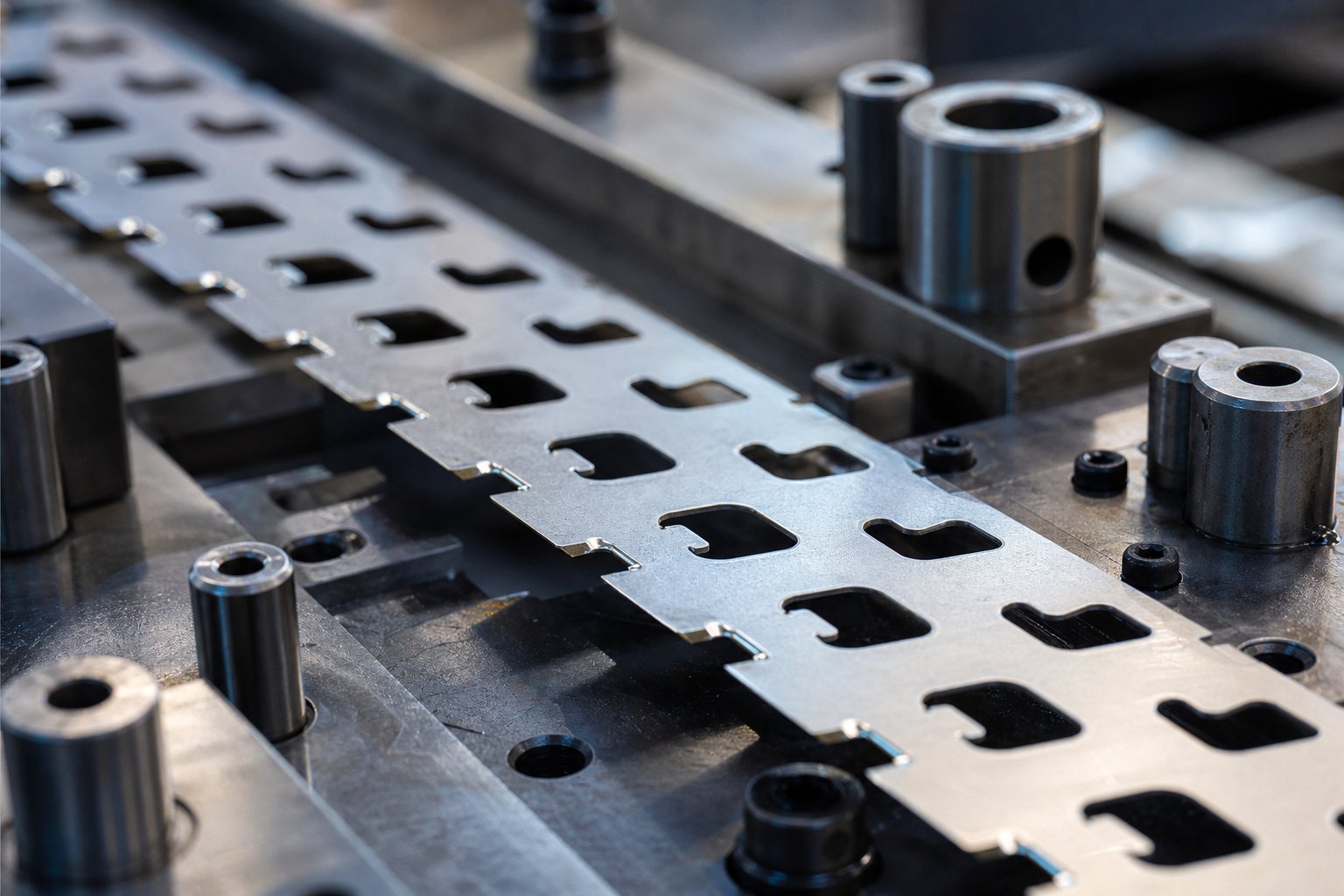
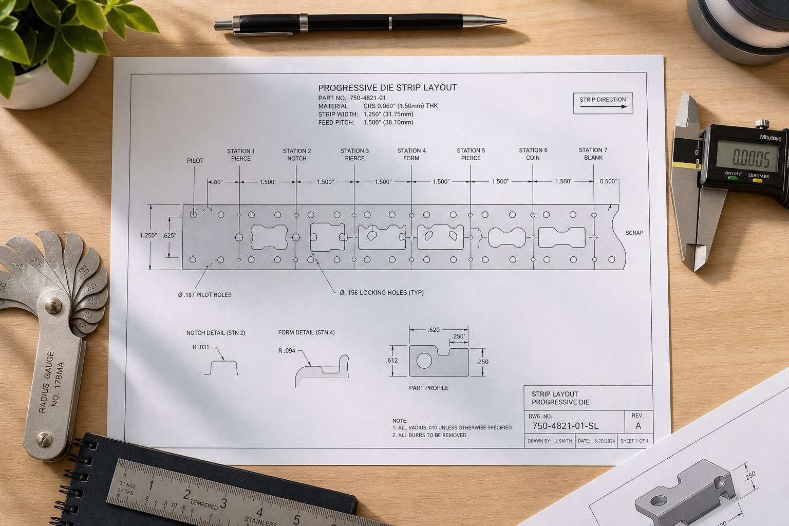
Bypass notches are small, deliberate material removals at specific locations along the carrier strip. Their job is straightforward: allow previously blanked, pierced, or formed areas of the strip to clear die components - punches, die buttons, lifters, and formed geometry - as the strip advances one pitch length forward.
Imagine a progressive stamping die with eight stations. Each press stroke feeds the strip forward by a fixed distance. Features created at station two must physically pass through stations three, four, five, and beyond without colliding with tooling. Bypass notches carve out the clearance path that makes this possible.
A bypass notch is a relief cutout in the carrier strip of a progressive stamping die that prevents previously processed features from interfering with downstream tooling as the strip feeds forward.
Why Every Progressive Die Needs Bypass Notches
The core engineering rationale comes down to interference prevention. In sheet metal stamping, the carrier strip - that extra material holding parts together as they travel station to station - must remain structurally sound while feeding cleanly through every die station. Without bypass notches, the strip collides with punches or formed geometry at adjacent stations, causing misfeed, buckling, slug pulling, or outright die damage.
A simple stamping definition of the problem: strip goes forward, previously worked material enters the space occupied by active tooling, and something breaks. The purpose of bypass notches in stamping dies is to eliminate that collision before it starts.
As Art Hedrick notes in The Fabricator, poor strip feeding in progressive dies leads to die and press damage, scrap, safety hazards, and downtime. Bypass notches are one of the primary design tools that prevent these failures at the strip layout stage - long before the die ever runs in production.
What is metal stamping without reliable strip progression? It is scrap, rework, and broken tooling. Getting bypass notch design right from the start eliminates a category of problems that no amount of press adjustment can fix after the fact.
How Bypass Notches Control Strip Progression in Progressive Dies
Every progressive die operates on one non-negotiable principle: the strip moves forward a fixed distance - the pitch - and every feature already cut or formed must pass through every downstream station without hitting anything. The metal stamping process relies on that rhythm. When you break it, you break the die.
Bypass notches are the mechanism that keeps that rhythm intact. They remove material from the carrier strip at precise locations so that previously worked geometry clears downstream tooling. The logic is simple, but the execution requires careful analysis of every station's tooling envelope relative to the strip's travel path.
Strip Feed Mechanics and Station Clearance
In the stamping process, the coil feeder advances the strip by exactly one pitch distance per press stroke. That pitch is the center-to-center distance between adjacent parts in the strip layout. Each time the strip indexes forward, every feature upstream - pilot holes, blanked openings, formed tabs, drawn cups - shifts one station closer to the exit.
Here is the critical point: a formed feature created at station three will physically occupy space at station four during the next press stroke, station five on the stroke after that, and so on. If any downstream station has a punch, die button, or lifter rail that occupies the same vertical or lateral space as that upstream feature, the strip cannot feed through without collision.
During strip layout planning, the die designer maps out the tooling envelope at each station - the three-dimensional space that punches, forming steels, and pressure pads occupy during the full press stroke. Wherever incoming strip material overlaps with that envelope, an interference zone exists. Each interference zone demands a bypass notch.
Carrier strip width plays a direct role here. Wider carriers offer more material to notch without sacrificing structural integrity, but they consume more coil stock. Narrower carriers limit how deep a notch can extend before weakening the strip's ability to feed. The die process balances these constraints early in the design sequence.
How Bypass Notches Prevent Strip Buckling and Misfeed
What happens when bypass notches are missing or undersized? The failure modes compound quickly:
- Strip lifting off lifters. When material collides with a downstream punch or die button during feed, the strip gets pushed upward or sideways. It lifts off the lifter rails, losing its guided path through the die.
- Buckling between stations. The feeder pushes the strip forward, but the strip cannot pass through the obstruction. Material compresses and buckles between the feed line and the blockage point. As Art Hedrick explains in The Fabricator, round lifters that fail to support the strip properly allow it to sag and fold onto itself - an effect amplified when bypass clearance is insufficient.
- Slug pulling. Partial interference can drag cut slugs upward during the feed stroke. These slugs end up on the die face and get stamped into subsequent parts, damaging both the tooling and the product.
- Progressive feed errors. A small interference at one station creates a slight short-feed. That error carries forward and compounds at every subsequent station, causing pilot holes to misalign, cuts to mismatch, and formed features to land off-target. In transfer stamping operations, a similar principle applies - parts must clear tooling between stations, though the transport mechanism differs.
These failures rarely appear as a single dramatic crash. More often, they show up as gradually increasing burr, intermittent misfeed alarms, or unexplained variation in part dimensions - all symptoms of interference that proper bypass notch design would have eliminated.
Placement Logic in the Strip Layout Process
Determining where bypass notches belong is a sequential engineering exercise. You cannot shortcut it. The decision process works through the strip layout station by station, checking each tooling component against the incoming strip profile.
- Map every station's tooling envelope. For each die station, document the full 3D space occupied by all punches, die buttons, forming steels, lifters, and pressure pads during the entire press stroke - not just at bottom dead center.
- Overlay the strip profile at each feed position. Track how the carrier strip, with all its previously cut and formed features, appears as it arrives at each station. Include the full strip width, existing cutouts, and any formed geometry that extends above or below the strip plane.
- Identify interference zones. Wherever the incoming strip profile overlaps with the station's tooling envelope, mark an interference zone. Pay attention to both lateral (across the strip width) and vertical (above and below the feed plane) conflicts.
- Define notch geometry per interference zone. For each identified conflict, determine the minimum material removal needed to provide clearance. Add a safety margin to account for feed tolerance, lateral strip wander, and any press-speed-related overtravel.
- Verify carrier strip integrity. After placing all bypass notches, confirm that the remaining carrier material is structurally sufficient to feed the strip through the die without buckling or excessive deflection.
- Assign notch cutting to an appropriate station. Decide which upstream station will cut each bypass notch. The punching stamping operation that creates the notch must occur before the strip reaches the station where clearance is needed - ideally in the first or second station of the die.
This workflow applies whether you are designing a ten-station die for a simple bracket or a thirty-station die for a complex automotive connector. The stamping manufacturing process demands that every notch placement decision be validated against the full travel path of the strip, not just the immediately adjacent station.
Geometry is only half the story, though. The shape and size of each notch - rectangular, angular, or radiused - depends on the specific interference profile, the material being stamped, and the structural demands on the carrier strip at that location.
Types of Bypass Notches and When to Use Each
Not all interference zones look the same, so not all bypass notches should look the same either. The geometry of each notch - its profile, orientation, and edge treatment - directly affects strip feeding behavior, carrier strip integrity, and long-term tool life. Yet among the various types of stamping dies discussed in tooling literature, bypass notch classification rarely gets the attention it deserves.
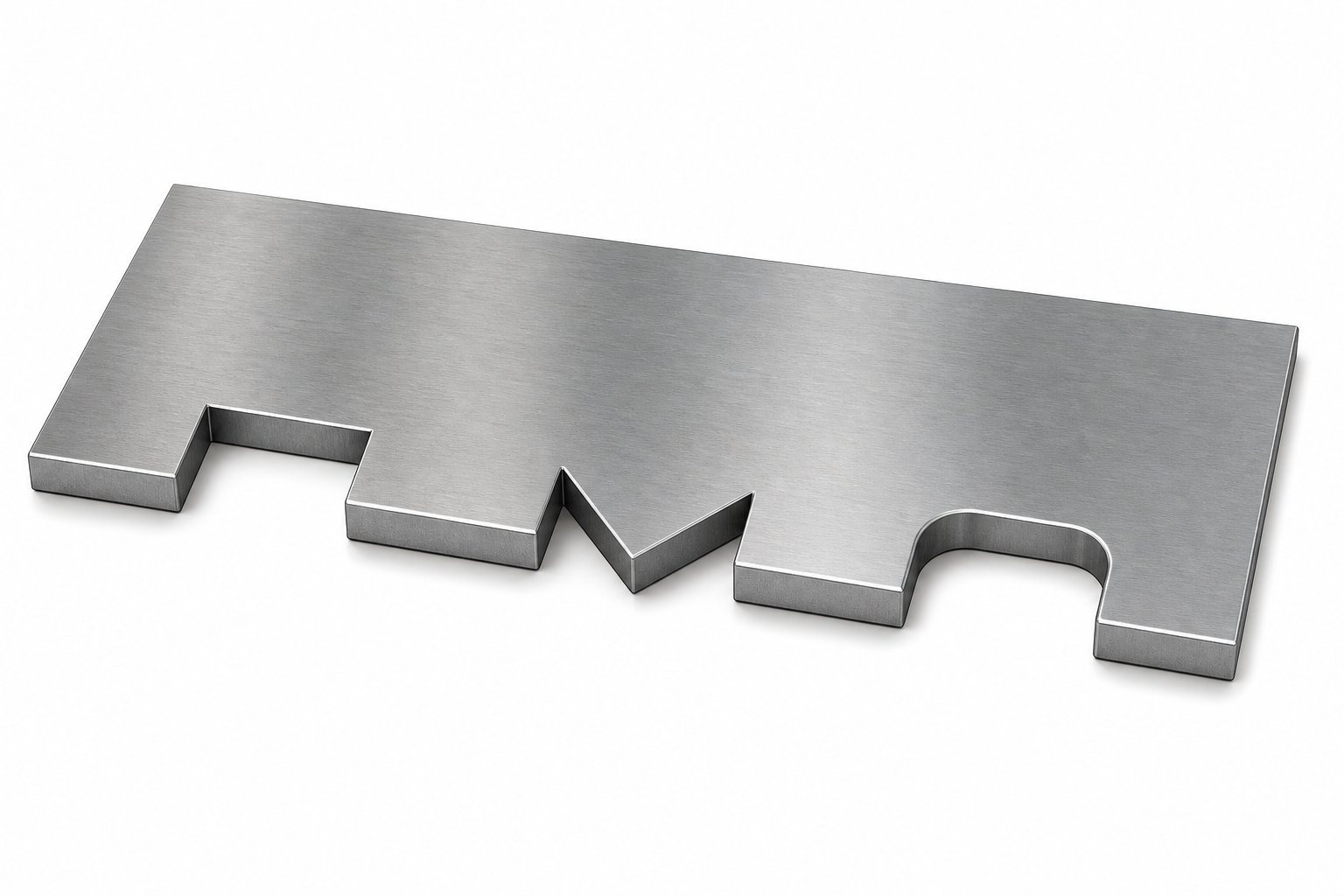
Three primary notch profiles cover the vast majority of progressive die applications: rectangular, angular (V-shaped), and radiused. Layered on top of that geometry choice is a configuration decision - whether the notch is positive or negative relative to the carrier strip. Each combination solves a different problem.
Rectangular Versus Angular Bypass Notch Profiles
Rectangular bypass notches are the workhorses of strip layout design. They feature straight, parallel walls oriented perpendicular to the feed direction, creating a clean, box-shaped cutout in the carrier strip. You will find them in most stamping dies where the interference zone has a simple, uniform profile - think a cylindrical punch or a flat-faced die button that needs clearance across a consistent width.
Why are they so common? Rectangular notches are straightforward to machine into die steels, easy to inspect dimensionally, and predictable in their clearance behavior. The punch that creates them is a simple geometry with no angled surfaces to maintain or resharpen. For standard clearance needs where the obstruction is well-defined and the strip material is forgiving, a rectangular profile gets the job done with minimal tooling complexity.
Angular or V-shaped notches serve a different purpose. When the interference geometry is directional - for example, a formed tab that extends at an angle relative to the feed path, or a situation where clearance is only needed on one side of the carrier - an angular notch provides targeted relief without removing more material than necessary. The angled walls also distribute stress more gradually than the abrupt corners of a rectangular cutout, reducing the risk of crack initiation at the notch boundary.
Think of it this way: rectangular notches answer the question "how much space do I need?" while angular notches answer "which direction do I need that space?" When strip width is tight and every millimeter of carrier material matters, the directional efficiency of a V-shaped notch can preserve structural integrity that a full rectangular cutout would compromise.
Positive and Negative Bypass Notch Configurations
Beyond profile shape, bypass notches fall into two fundamental configurations that describe how clearance is achieved relative to the carrier strip itself.
Negative bypass notches are what most engineers picture first - material is removed from within the carrier strip to create an opening that tooling can pass through. The strip arrives at a station with a cutout already present, and the downstream punch or die component occupies that now-empty space during the press stroke. Negative notches are the default approach when interference occurs within the strip's existing footprint.
Positive bypass notches work the opposite way. Instead of removing material from the carrier, the strip layout includes extra material - projections or tabs that extend beyond the nominal blank outline - specifically to route the carrier around an obstruction. The strip is wider or differently shaped at that location, allowing it to travel a path that avoids the interference zone entirely.
When do you choose one over the other? Negative and positive bypass notches in sheet metal stamping dies serve the same clearance function, but the design scenarios that favor each differ significantly:
- Negative notches work best when the interference zone is small relative to the carrier strip width, and removing material will not compromise feed stability. They are simpler to implement and add no extra strip width.
- Positive notches become necessary when the interference zone is large or centrally located, making material removal impractical without destroying the carrier. They require additional coil width - increasing material cost - but preserve carrier continuity.
- Material utilization often tips the decision. In high-volume production where coil cost dominates, designers favor negative notches to keep strip width minimal. For complex parts where carrier integrity is critical, positive notch configurations justify the added material.
Understanding negative and positive bypass notches in sheet metal forming stamping dies is essential for making informed strip layout decisions. The choice is never purely geometric - it reflects a balance between material cost, carrier strength, and the specific obstruction that needs clearance.
Radiused Notch Geometry for Stress Reduction
Sharp internal corners are the enemy of high-speed strip feeding. Every abrupt corner in a bypass notch acts as a stress riser - a point where cyclic loading during rapid feed-and-stop motion concentrates until the material fatigues and cracks. During tryout at slow press speeds, these corners survive just fine. At 600 strokes per minute in production, they become fracture initiation points.
Radiused transitions at notch corners distribute that stress over a larger area, dramatically extending the strip's fatigue life at speed. The radius does not need to be large - even a small fillet at each internal corner can multiply the number of feed cycles before failure. The specific radius depends on material thickness, tensile strength, and press speed, but the principle is universal: never leave a sharp internal corner on a bypass notch that will run at production rate.
Radiused geometry also improves slug ejection from the notch punch, reduces burr formation at the notch edges, and extends punch life by eliminating the sharp corners that wear fastest on the cutting tool itself.
| Notch Type | Geometry | Typical Application | Stress Behavior | Tooling Complexity |
|---|---|---|---|---|
| Rectangular | Straight parallel walls, flat bottom | Standard clearance for uniform interference zones | High stress at corners without radii | Low - simple punch geometry |
| Angular / V-Shaped | Angled walls converging to a point or flat | Directional clearance, tight strip width situations | Moderate - gradual stress distribution along angled walls | Medium - angled punch faces require precise grinding |
| Radiused | Any profile with filleted internal corners | High-speed production, fatigue-sensitive materials | Low - stress distributed over curved transitions | Medium - radius must be consistent and inspectable |
| Positive Configuration | Added material routing around obstruction | Large interference zones, carrier integrity critical | Low - no material removal weakens carrier | Higher - strip layout requires wider coil and modified blanking |
| Negative Configuration | Material removed from within carrier strip | Small to moderate interference zones | Variable - depends on notch size relative to carrier width | Low to medium - standard punch-and-die cutout |
In practice, most production stamping dies combine these approaches. A single strip layout might use rectangular negative notches for simple punch clearances, angular notches where strip width is constrained, and radiused corners on all of them to survive at speed. The notch type is not a global decision - it is a station-by-station, interference-by-interference judgment call driven by the specific geometry each notch must clear.
Selecting the right notch profile and configuration gets you clearance. But clearance alone is not the whole picture - the dimensions of each notch, the tolerances on its position, and its relationship to pilot holes and station boundaries determine whether that clearance actually works reliably across millions of press strokes.
Bypass Notch Geometry and Dimensional Parameters Explained
Clearance without precision is just a guess. A bypass notch that is roughly in the right place and approximately the right size might survive tryout - but production at speed punishes approximation. Every geometric parameter on a bypass notch exists for an engineering reason, and getting any one of them wrong costs you strokes per minute, strip integrity, or both.
In stamping die design, the dimensional specification of bypass notches follows a logic tied directly to the interference zone they serve, the material they cut through, and the positional system that keeps everything in registration. Here is what each parameter controls and why it matters.
Critical Dimensions and Tolerances for Bypass Notch Design
Three primary dimensions define every bypass notch: depth, width, and corner radius. Each one responds to a different engineering constraint, and each carries a different consequence when undersized.
Notch depth is measured perpendicular to the feed direction - how far into the carrier strip the notch extends from the strip edge. This dimension must clear the widest point of the interference zone plus a safety margin that accounts for lateral strip wander during feeding. If the strip drifts even slightly off-center (and it will), a notch with zero margin becomes a notch that does not fully clear. Typical practice adds a margin beyond the maximum tooling envelope, scaled to press speed and feeder accuracy. Faster presses and less precise feeders demand larger depth margins.
However, depth is constrained by carrier strip width. In metal stamping die design, the carrier must retain enough cross-sectional material after notching to feed without buckling or tearing. A general guideline: notch depth should not exceed 60-70% of the carrier strip width, though the actual limit depends on material thickness, tensile strength, and the number of notches along the strip length.
Notch width runs parallel to the feed direction. It must be wide enough so that the obstruction clears the notch across the full feed stroke - including any overtravel. Feed tolerance is the key variable here. If the feeder overshoots by a small amount on any given stroke, the notch must still provide full clearance at maximum overtravel. Width also needs to account for the physical size of the tooling component being bypassed, measured along the feed axis.
Consider a punch that occupies 8mm along the feed direction. The notch width must cover that 8mm plus twice the feed tolerance (once for potential over-feed, once for potential under-feed on the previous stroke) plus any additional margin for burr or debris buildup on the punch face.
Corner radius at internal notch transitions prevents fatigue cracking. As Xometry's stamping design guide notes, all corners of a blank design should include a radius of at least half the material thickness. For bypass notches, the same principle applies - sharp internal corners concentrate cyclic stress during high-speed feeding, initiating cracks that propagate until the carrier strip fractures. The minimum acceptable radius increases with material thickness and tensile strength, and decreases with ductility.
Angular orientation applies to non-rectangular notch profiles. When a V-shaped or angled notch is used, the angle of the notch walls relative to the feed direction determines the effective clearance at different points along the feed stroke. Proper orientation ensures maximum clearance coincides with the moment the obstruction passes through the notch.
Here are the key geometric parameters every tooling engineer should define on bypass notch specifications within their sheet metal stamping dies:
- Depth (perpendicular to feed): Provides lateral clearance past the widest interference zone, including margin for strip wander.
- Width (parallel to feed): Ensures full clearance across the entire feed stroke, including overtravel and feeder tolerance.
- Internal corner radius: Prevents stress concentration and fatigue cracking at production speeds. Minimum half the material thickness.
- Angular orientation: Aligns directional clearance with the motion path of the obstruction relative to the strip.
- Depth-to-carrier-width ratio: Maintains structural integrity of the carrier strip after material removal. Limits vary by material grade.
- Edge condition and surface finish: Controls burr size and edge quality at the notch boundary, preventing snag points during feed.
Positional Relationships to Pilot Holes and Station Boundaries
A perfectly dimensioned notch in the wrong location does nothing. Positional accuracy of bypass notches references two anchors in every progressive die strip layout: pilot hole centers and station centerlines.
Pilot holes are the master datum for the entire strip. Every feature - blanked openings, formed geometry, and bypass notches - is positioned relative to pilot hole centers. This matters because the pilot pins physically pull the strip into exact registration at every press stroke. If a bypass notch drifts from its intended position relative to the pilot hole, it drifts relative to the tooling it is supposed to clear.
In practice, positional tolerances on bypass notches are tighter than you might expect for a feature that "just" provides clearance. The reason ties back to margin management. If the notch depth margin is designed at a specific value assuming perfect position, and the notch position varies by even a fraction of that margin, the effective clearance shrinks below the safe threshold on some percentage of strokes.
Station-to-station placement follows a similar logic. Each bypass notch must be located so that it fully clears the target obstruction across the entire feed stroke. That means the leading edge of the notch (in the feed direction) must pass completely beyond the obstruction before the strip stops, and the trailing edge must not arrive at the obstruction before the strip begins moving. Feed-direction placement accounts for the nominal pitch distance plus maximum feed tolerance in both directions.
As discussed in MetalForming Magazine's strip analysis, improper feed-release timing can cause the strip to slide forward or backward after the grip rolls open. This means bypass notch width must accommodate not just mechanical overtravel but also the potential for post-release drift before pilot engagement. If the notch is too narrow, that momentary drift places the carrier material back into the interference zone during the instant before the pilot pins lock the strip into final position.
For complex stamping die components like cams, forming steels with angular faces, or multi-level punches, the positional relationship between the notch and the obstruction becomes three-dimensional. The notch must clear the widest cross-section of the component at the specific vertical position the strip occupies during the feed stroke - which is determined by lifter height, not bottom dead center geometry. Engineers who dimension bypass notch clearance against the die at full closure, rather than at the feed plane elevation, end up with notches that look adequate on paper but interfere in practice.
These dimensional and positional parameters form the quantitative backbone of every bypass notch specification. But numbers alone do not account for how different materials respond to being notched - a parameter set that works perfectly in mild steel can crack high-strength steel or gall aluminum at the notch edges.
Material-Specific Bypass Notch Design Considerations
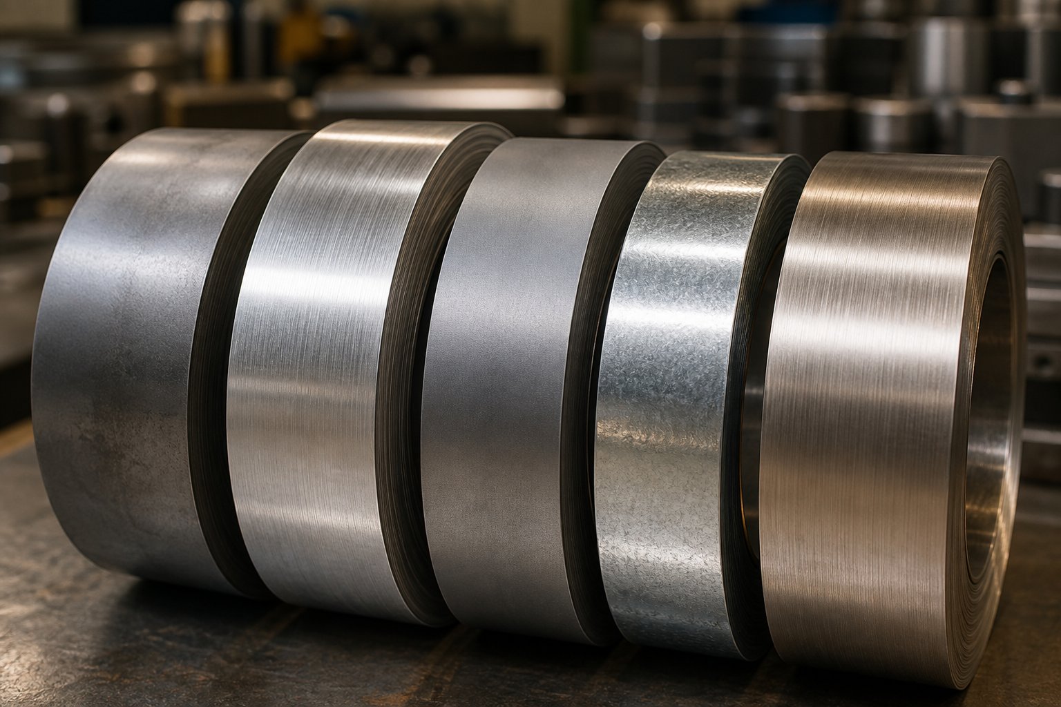
A notch dimensioned for mild steel will not behave the same way in dual-phase steel or aluminum. Material grade, thickness, and mechanical properties directly change how the carrier strip responds to having material removed - how it feeds, how it fatigues, and how the cut edges hold up over hundreds of thousands of strokes. Treating all materials the same is one of the fastest ways to turn a solid strip layout into a production headache.
Each material brings its own combination of ductility, tensile strength, work-hardening behavior, and surface characteristics. These properties dictate minimum corner radii, depth margins, edge condition requirements, and even the surface finish needed on the notch tooling itself. Here is how the parameters shift across the most common materials in steel sheet stamping and beyond.
Mild Steel and Cold Rolled Steel Notch Parameters
Mild steel and standard cold rolled steel stamping grades (CRS like 1008, 1010, 1018) are the most forgiving materials for bypass notch design. Their combination of moderate tensile strength, good ductility, and predictable shear behavior means that standard design rules work without special accommodation.
For carbon steel stamping in these common grades, the baseline parameters apply cleanly:
- Minimum internal corner radius: 0.5x material thickness. This standard ratio, well-established across industry notching guidelines, prevents stress concentration without requiring generous fillets that consume extra clearance space.
- Notch depth margin: Standard safety margins beyond the tooling envelope are sufficient. Mild steel does not spring back aggressively, so the strip sits predictably on the lifter rails during feed.
- Edge condition: A clean shear with normal burr height is acceptable. Mild steel does not crack propagate easily from a standard sheared edge.
- Tooling surface treatment: Standard tool steels (D2, A2) with conventional surface finish handle these grades without special coatings.
Mild steel serves as the baseline because it is predictable. The work-hardening rate is moderate, the elongation before fracture is generous, and the material does not fight you at the notch boundaries. If you are designing your first strip layout and want to validate your bypass notch logic, stamped steel in these grades will expose layout errors without adding material-behavior complications on top.
High-Strength Steel and AHSS Considerations
Advanced High-Strength Steels change the calculus significantly. Materials like Dual-Phase (DP600, DP780, DP980), TRIP steels, and Martensitic grades carry substantially higher tensile strength but reduced elongation and ductility. The carrier strip behaves more rigidly, fatigues faster at stress risers, and punishes sharp geometry that mild steel would tolerate.
What changes for bypass notch design?
Corner radii must increase. Where mild steel accepts a radius of 0.5x material thickness, AHSS demands significantly more - often 1.0x to 1.5x thickness as a minimum. As noted in automotive notching research, AHSS requires generous corner radii to prevent parts from splitting during fatigue cycles. The same principle applies to carrier strip notches: sharp internal corners that survive indefinitely in mild steel will initiate cracks within thousands of strokes in DP980.
Notch width needs expansion. AHSS springs back more aggressively after each feed-and-stop cycle. The strip does not sit as flat on lifter rails, and its positional behavior is less predictable. Wider bypass notches compensate for this reduced positional consistency, ensuring clearance even when the strip is not perfectly seated.
Carrier strip width may need to increase. Because AHSS is less ductile, the carrier strip is more prone to fracture at notch locations under the cyclic loading of high-speed feeding. To maintain the same structural integrity that mild steel provides at a given carrier width, AHSS strip layouts often require a wider carrier - which means more coil stock and higher material cost. It is a direct tradeoff between strip reliability and material utilization.
Tooling wear accelerates. The higher shock load when punching AHSS notches degrades punch edges faster. Powdered metallurgy steels or carbide-tipped punches become necessary for notch stations that cut high-strength material at production volumes.
Aluminum and Stainless Steel Adaptations
Aluminum and stainless steel each introduce unique challenges that mild steel and even AHSS do not present.
Aluminum is softer and more ductile than steel, which sounds like it should make notch design easier. It does not. The aluminum stamping process brings a specific surface-interaction problem: galling. Research at Oakland University's Center of Advanced Manufacturing and Materials demonstrated that aluminum particles adhere to die surfaces during sliding contact, causing scratches on the workpiece and adhesive wear on tooling. At bypass notch locations, where the sheared edge of the strip repeatedly slides past die components during feeding, galling builds deposits that reduce effective clearance over time.
Prevention requires polished tooling surfaces and often hard-chrome or TiCN coatings on die components adjacent to notch areas. The research found that surface roughness directly influences the galling threshold - smoother die surfaces (like hard-chromed D6510 cast iron) resisted galling at significantly higher contact pressures than rougher alternatives. For bypass notch tooling in aluminum, this means the punch cutting the notch and any die surface the notched strip slides against must maintain a finer surface finish than steel applications demand.
Corner radii on aluminum notches should be generous not because of fatigue cracking (aluminum is ductile enough at typical thicknesses) but because sharp corners create burr and tearing that generate the loose particles responsible for galling downstream.
Stainless steel presents a work-hardening challenge. Every feed cycle plastically deforms the carrier strip slightly at notch boundaries. In mild steel, this minor deformation stabilizes quickly. In austenitic stainless grades (304, 316), each deformation cycle increases the local hardness and brittleness at the notch edge. Over a production run of hundreds of thousands of strokes, the notch edges progressively embrittle until micro-cracks form and propagate.
Designing bypass notches for stainless steel means accounting for this cumulative hardening. Larger radii slow the hardening rate at corners. Polished and coated notch punches produce cleaner shear edges with less initial damage for hardening to build on. And depth margins should account for the fact that work-hardened notch edges behave differently at stroke 500,000 than at stroke 5,000.
| Material | Min. Corner Radius | Depth Margin | Edge Condition Requirement | Tooling Surface Treatment |
|---|---|---|---|---|
| Mild / Cold Rolled Steel | 0.5x thickness | Standard (feed tolerance + wander) | Normal sheared edge acceptable | Standard tool steel (D2, A2), conventional finish |
| High-Strength Steel / AHSS | 1.0x–1.5x thickness | Increased (springback + positional variation) | Minimal burr, clean fracture zone critical | PM tool steel or carbide; TiCN coating recommended |
| Aluminum | 0.5x–1.0x thickness | Standard + galling deposit allowance | Smooth shear, minimal particle generation | Hard-chrome or TiCN; polished to low Ra |
| Stainless Steel (Austenitic) | 1.0x–1.5x thickness | Increased (work-hardening progression) | Polished shear edge to minimize hardening initiation | High-hardness tool steel; TiAlN or similar coating |
The pattern across all these materials is consistent: the further a material deviates from mild steel behavior - whether through higher strength, adhesion tendencies, or work-hardening - the more conservative your bypass notch parameters need to be. Radius increases, margins grow, surface finish requirements tighten, and tooling costs rise accordingly.
Getting the material-specific parameters right keeps the strip feeding cleanly. But even a perfectly parameterized notch will cause problems if the design contains one of several common engineering mistakes that show up repeatedly on production floors - errors that are easy to avoid when you know what to watch for.
Common Bypass Notch Mistakes and Their Production Consequences
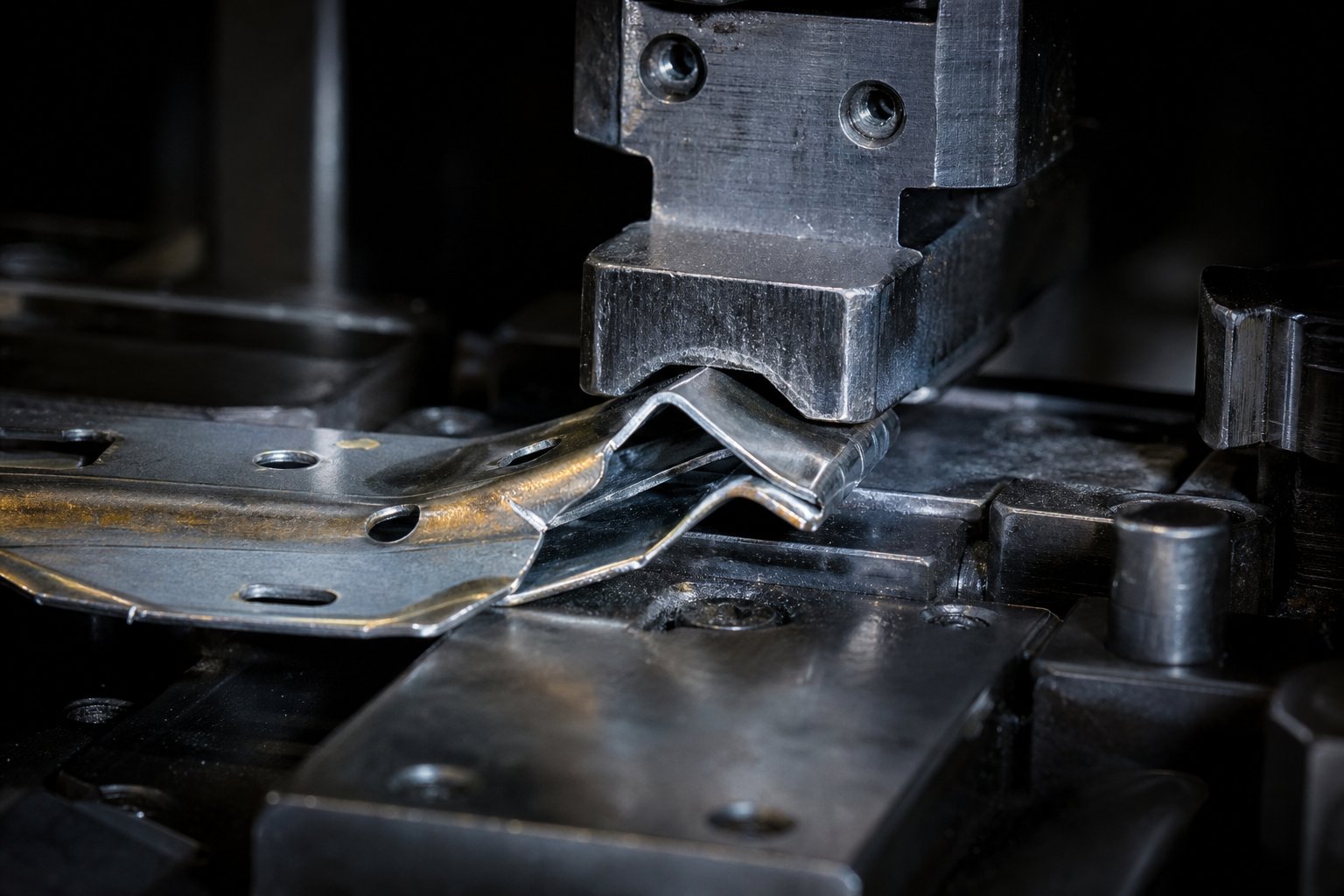
Knowing the right parameters and knowing what goes wrong when you ignore them are two different kinds of knowledge. The first lives in the design office. The second lives on the production floor at 2 a.m. when the press trips on a misfeed alarm for the third time that shift. Most bypass notch failures do not announce themselves during tryout. They wait until the press hits production speed and the strip has been running long enough for wear, thermal expansion, and cumulative error to expose every marginal clearance decision.
The mistakes below show up repeatedly across stamping operations producing everything from automotive brackets to precision die stamping applications for connectors. Each one follows the same pattern: a design choice that looks acceptable on paper or at slow speed creates a failure mechanism that only activates under real production conditions.
Undersized Notches and Die Crash Scenarios
Insufficient notch depth or width is the most common bypass notch error - and one of the most expensive. The failure mechanism is deceptively gradual. An undersized notch does not cause an immediate crash. Instead, it creates partial interference: the strip edge just barely contacts a downstream punch or die button during feed progression. Each stroke leaves a tiny witness mark, builds a slight burr deposit on the interfering surface, and displaces the strip laterally by a fraction of a millimeter.
Over hundreds or thousands of strokes, that burr deposit grows. The lateral displacement compounds. The strip begins short-feeding by an amount too small to trip the misfeed sensor but large enough to degrade pilot hole registration. Stamping parts downstream start showing dimensional drift - a wall angle changes, a hole shifts, an edge dimension creeps out of tolerance.
Then the crash happens. The accumulated positional error reaches a tipping point where the strip can no longer advance past the obstruction. The feeder pushes, the strip buckles, and the press drives the upper die into a buckled mass of material. The result: broken punches, damaged die buttons, scored forming steels, and hours of unplanned downtime to disassemble, inspect, and repair.
What makes this failure particularly frustrating is that progressive die failures rarely begin with a single catastrophic event - they develop through cumulative wear and strip instability. An undersized bypass notch accelerates that exact progression. The fix is straightforward during design: add adequate depth margin beyond the tooling envelope and width margin beyond the feed tolerance. The fix after a crash is costly: repair the die, revalidate clearances, and potentially rework the notch station tooling.
Stress Concentration Failures at High Production Speeds
Sharp internal corners on bypass notches are the second most common mistake, and the one that creates the most dramatic production failures. Here is why they survive tryout but kill production runs: during die tryout, the press runs at 20-40 strokes per minute. The strip feeds slowly, decelerates gently, and experiences minimal cyclic stress at notch corners. Everything looks fine. The strip feeds cleanly, parts come out to spec, and the die gets approved for production.
At production speed - 200, 400, 600 strokes per minute - the physics change completely. Every feed cycle accelerates and decelerates the entire strip mass in a fraction of a second. That cyclic loading concentrates at every sharp internal corner of every bypass notch, every single stroke. The mechanism is classic fatigue failure: micro-cracks initiate at stress concentration points, propagate a tiny amount each cycle, and eventually reach critical length. The strip fractures.
When the carrier strip fractures at a bypass notch during a production run, the consequences cascade instantly. The downstream portion of the strip - still attached to partially completed metal stamping components - stops moving. The upstream portion, still being pushed by the feeder, buckles into the die. The press may cycle one or two more strokes before the tonnage monitor or misfeed sensor reacts, driving punches into mispositioned material and potentially shattering carbide inserts.
The connection between sharp corners and cracking in high-speed stamping is well established - improper die design with sharp corners or sudden cross-section changes creates stress concentration points that lead to cracks. Bypass notch corners are no exception. The solution is a radiused transition at every internal corner, sized according to material thickness and tensile strength as detailed in the geometry chapter above. A small investment in radius grinding during die build prevents catastrophic strip fracture in production.
Carrier Strip Weakening and Feed Instability
The opposite extreme from undersized notches is equally dangerous: notches that are too deep relative to carrier strip width. When a designer faces a large interference zone and responds by cutting an aggressive notch that consumes most of the carrier cross-section, the remaining material may lack the structural stiffness to feed reliably.
As The Fabricator notes, carrier strips that are too weak to support the weight of the strip cannot be fed smoothly, and if the strip cannot be fed smoothly, a die crash will likely result. Bypass notches that remove too much material create exactly this condition - locally weakened sections that sag between lifter rails, oscillate during rapid feeding, or flex laterally enough to miss pilot engagement.
The symptoms of carrier weakening are subtle at first. Pilots engage inconsistently, causing slight variation in stamped part dimensions. Feed sensors may trip intermittently without a clear pattern. Lifter marks appear on the strip at unexpected locations as weakened sections droop onto die surfaces during feed. Over time, the weakened carrier sections develop fatigue cracks from the repeated flexing, eventually fracturing - the same end result as stress concentration failure, but from a completely different root cause.
Two additional mistakes compound these primary errors and deserve attention. Ignoring material springback in notch clearance calculations - particularly common when transitioning a die design from mild steel to AHSS - results in notches that provide adequate static clearance but insufficient dynamic clearance when the strip rebounds after each feed cycle. And failing to account for burr direction when positioning notches creates a scenario where bypass notches burr formation stamping edges face toward die components, catching and dragging during feed. Burrs always form on one side of a sheared edge; if that side faces the obstruction the notch was designed to clear, the effective clearance is reduced by the burr height - sometimes enough to cause interference.
Here is a quick-reference summary of each mistake paired with its production consequence:
- Insufficient notch depth: Progressive burr buildup, gradual positional drift, eventual die crash from strip buckling.
- Insufficient notch width: Partial interference during overtravel, intermittent misfeed alarms, inconsistent pilot registration.
- Sharp internal corners: Cyclic fatigue cracking at production speed, catastrophic strip fracture, cascade damage to multiple die stations.
- Excessive notch depth (carrier weakening): Strip sag between lifters, feed instability, intermittent dimensional variation, eventual fatigue fracture.
- Ignoring springback in clearance: Dynamic interference on rebound, increased strip drag, accelerated punch wear at adjacent stations.
- Wrong burr orientation: Burr-side facing tooling reduces effective clearance, creates drag during feed, accelerates wear on die components.
- No radius on notch punch corners: Premature punch edge breakdown, growing burr on notch edges, reduced strip fatigue life from poor edge quality.
Looking at these stamping examples of failure, a pattern emerges: every mistake involves either removing too little material (creating interference), removing too much material (destroying carrier integrity), or removing material with the wrong geometry (creating stress risers or burr problems). The design challenge is finding the middle ground - and that middle ground shifts depending on how the bypass notch interacts with other progressive die features like pilot holes, lifters, and scrap management systems.
How Bypass Notches Integrate with Other Progressive Die Features
A bypass notch never exists in isolation. It sits within a system of interdependent features - pilot holes that locate the strip, lifters that elevate it, carrier strips that transport it, and scrap management paths that remove waste cleanly. Change one of those features, and the bypass notch requirements shift with it. This interconnection is what makes metal stamping dies more than a collection of punches and die buttons - they are integrated mechanical systems where every component references every other.
Designing bypass notches without considering their neighbors is like sizing a foundation without knowing the building above it. In industrial metal stamping, where progressive dies run millions of cycles at high speed, that kind of compartmentalized thinking produces dies that work in theory and fail in practice.
Bypass Notches and Pilot Hole Coordination
Pilot holes are the positional backbone of the entire strip layout. Every feature on the strip - blanked openings, formed geometry, and bypass notches - derives its location from the pilot hole datum. When pilot pins engage the strip at each press stroke, they correct minor feeding inaccuracies and pull everything into precise alignment before any cutting or forming occurs.
This means bypass notches must be sequenced so that pilot registration happens before any notch-related issue can accumulate error. If a notch is cut at station one and the pilot hole is not punched until station two, any feed inaccuracy on that first stroke goes uncorrected - and the notch lands slightly off its intended position. That positional error carries through every subsequent station, potentially reducing the effective clearance the notch was designed to provide.
The practical rule: pilot holes should be punched at the earliest possible station, ideally at the same station or before any bypass notch cutting occurs. When both features compete for space in the first station, the pilot hole takes priority. As noted in progressive die design practice, pilots align the strip before each operation - without them, minor feeding errors accumulate and create tolerance drift across stations. Bypass notch positional accuracy depends entirely on that pilot registration being established first.
Additionally, the physical distance between a bypass notch and its nearest pilot hole affects the strip's local stiffness at the registration point. If a deep notch sits immediately adjacent to a pilot hole, the carrier material between them may flex under pilot engagement force. This creates a condition where the pilot registers accurately at its own location but the notch - just millimeters away in weakened material - deflects slightly off-position. Experienced stamping tool and die engineers maintain a minimum distance between notch edges and pilot holes, typically no less than twice the material thickness.
Interaction with Lifters and Strip Stability
Lifters raise the strip above the die surface between press strokes, allowing it to advance freely to the next pitch position. Their placement must account for where bypass notches have removed carrier material - because a lifter positioned beneath a notch cutout has nothing to support.
Imagine a lifter rail positioned directly under a deep negative bypass notch. When the strip feeds forward, the notched section passes over that lifter with minimal or no material contact. The strip sags at that point, losing its guided elevation. If it sags far enough, formed features on the strip can drag across die surfaces during feed, causing scratches, burr accumulation, or - at high speed - enough friction to short-feed the strip.
The design coordination works both directions:
- Lifter spacing must match structurally sound carrier sections. After all bypass notches are placed, map the remaining solid carrier material along the feed path. Lifters belong under those solid sections, never under notch openings.
- Notch locations may need adjustment for lifter support. If an interference zone coincides with the only available lifter position, the designer faces a tradeoff - either relocate the lifter (which may affect strip stability elsewhere) or modify the notch geometry to leave a narrow support bridge at the lifter contact point.
- Strip weight between lifters creates deflection. In long-pitch dies with heavy carrier strips, the span between lifters determines how much the strip sags under its own weight. Bypass notches that reduce carrier cross-section increase that deflection. For automotive stamping dies with large pitch distances, this sag can become significant enough to affect feed height consistency.
The process layout planning described by Art Hedrick in The Fabricator reinforces this point - carrier strength must be sufficient to move the part from station to station without buckling, severely flexing, or deforming. Bypass notch placement decisions directly affect whether that strength threshold is maintained at every lifter span along the strip.
Scrap Strip Management and Material Utilization
Every bypass notch generates a scrap slug. That slug must be ejected cleanly from the die - downward through the die block, or laterally off the die face - without jamming, rebounding, or interfering with subsequent press strokes. Scrap management is not an afterthought; it is a design requirement that influences notch geometry, station selection, and die shoe layout.
Notch scrap integrates with the overall strip scrap strategy in several ways:
- Slug ejection path. The die block below each notch punch must have a clearance hole large enough for the slug to fall freely. If the slug is too large for the available clearance opening, the notch geometry may need to change - or the slug may need to be cut in two separate operations at adjacent stations.
- Die shoe parallel placement. Parallels that support the die shoe on the press bolster cannot be positioned beneath scrap ejection paths. Bypass notch locations affect where parallels can go, which in turn affects die shoe rigidity. As The Fabricator's die essentials series notes, only certain areas can include parallels to support the die shoe when scrap must fall freely onto a collection system.
- Scrap chute interference. Multiple scrap streams from blanking, piercing, and notch operations all exit the die simultaneously. If a bypass notch slug and a piercing slug share the same exit zone beneath the die, they can collide and jam - especially at high production speeds where slug ejection timing becomes critical.
Material utilization is the other side of this equation. Bypass notches consume material that could otherwise be part of the finished product or at least minimize coil width. Intelligent notch design minimizes added scrap without compromising clearance function. Techniques include:
- Using angular notch profiles that remove only the material within the actual interference cone, rather than a full rectangular cutout that provides clearance in areas where none was needed.
- Combining bypass notch cuts with adjacent blanking operations so that a single punch creates both the part profile and the bypass clearance - eliminating the need for a separate notch station and reducing total scrap.
- Optimizing notch depth to the minimum required clearance plus margin, rather than defaulting to full-depth cuts that remove more carrier material than the interference zone demands.
In high-volume metal stamping tooling applications - particularly in automotive and appliance sectors - even small per-part material savings compound into significant cost reductions across millions of units. A bypass notch that is 2mm deeper than necessary across a strip running 50 million parts per year represents measurable waste. The stamping tooling engineer's job is to find the minimum notch envelope that satisfies clearance, maintains carrier integrity, and ejects scrap cleanly.
For engineers working through complex strip layout challenges where bypass notch placement intersects with lifter coordination, material flow optimization, and scrap path planning, YICHEN's stamping die engineering team offers design support for progressive die applications that demand integrated solutions across all these interacting features.
Each of these relationships - pilot coordination, lifter interaction, and scrap management - demonstrates why bypass notch design is a system-level activity. The notch does not exist in a vacuum. Its geometry, position, and cutting sequence depend on decisions made about every other metal stamping die component in the strip layout. Getting the notch right means getting the system right - and that requires a structured workflow for making these interdependent decisions in the correct order.
Bypass Notch Design Best Practices for Tooling Engineers
System-level understanding is only useful if it translates into repeatable action. Everything covered so far - notch types, geometry parameters, material adaptations, integration with lifters and pilots - collapses into a single practical question: what does the design workflow actually look like from start to finish? The answer is a structured sequence that eliminates guesswork and produces bypass notches sheet metal forming operations can rely on at full production speed.
Step-by-Step Bypass Notch Design Workflow
Whether you are laying out a twelve-station bracket die or a forty-station connector tool, the decision sequence follows the same logic. Here is the workflow that consistently produces reliable results in the metal stamping manufacturing process:
- Complete the part nesting and station sequencing first. Bypass notch decisions depend on knowing which operations occur at which stations. Finalize your blanking, piercing, forming, and idle station assignments before touching notch design.
- Map interference zones at every station. For each die station, overlay the incoming strip profile (including all upstream features) against the full tooling envelope - punches, die buttons, forming steels, and pressure pads through the entire press stroke, not just at bottom dead center.
- Select notch type per interference zone. Choose rectangular, angular, or positive/negative configurations based on the geometry of each obstruction, available carrier width, and material grade. Use angular profiles where strip width is tight; use positive configurations where carrier integrity cannot tolerate material removal.
- Dimension each notch with appropriate margins. Set depth to clear the widest interference point plus lateral wander margin. Set width to cover the obstruction length plus feed tolerance in both directions. Apply corner radii based on material thickness and tensile properties.
- Verify carrier strip structural integrity. After placing all notches, confirm that remaining carrier cross-sections can support the strip weight between lifter spans without excessive sag or flex. Check that no two adjacent notches create a combined weakness that individual analysis would miss.
- Coordinate with pilot holes and lifter positions. Confirm pilots are punched before or simultaneously with notch cuts. Verify lifters sit under solid carrier sections, not beneath notch openings.
- Validate scrap ejection paths. Ensure each notch slug has a clear drop path through the die block without interfering with adjacent scrap streams or die shoe parallels.
- Document notch specifications on the die print. Call out depth, width, radius, positional tolerance from pilot datum, and burr direction for every bypass notch. As MetalForming Magazine's design laws emphasize, if it needs to be done, it needs to be on the print - every detail clearly defined with no room for interpretation.
This sequence works because each step builds on confirmed decisions from the step before. Skipping ahead - dimensioning notches before mapping interference zones, or selecting notch types before finalizing station sequencing - introduces assumptions that collapse during tryout.
Design-for-Manufacturability Principles Applied to Bypass Notches
Well-designed bypass notches do more than prevent interference. They directly influence three downstream outcomes that define a die's production value:
- Maintenance intervals. Notches with proper radii and adequate margins reduce wear on adjacent tooling. When a strip feeds without dragging or partial contact, punch edges stay sharp longer, forming steels stay clean, and the die runs longer between service stops. Metal stamping design decisions made during layout directly set the maintenance clock.
- Die longevity. Catastrophic failures - strip fracture, die crashes from buckled material - are the events that shorten die life dramatically. Every best practice above exists to prevent those events. A die that never crashes lasts orders of magnitude longer than one that crashes even occasionally.
- Achievable press speed. Strip stability at speed is the ultimate test of bypass notch quality. A strip that feeds cleanly at 400 strokes per minute but fractures at 500 is limited by its weakest notch. Proper radii, adequate carrier integrity, and correct dimensional margins are what separate a die that runs at target speed from one that needs to be dialed back. Advanced metal stamping techniques in high-speed production depend on these details being right from the start.
The bypass notches sheet metal forming purpose comes down to this: they exist to let the strip move freely so the die can do its work at full speed without self-destructing. Every parameter, every radius, every positional tolerance serves that single objective.
The purpose of every bypass notch is to provide the minimum material removal that achieves full clearance, maintains carrier integrity, and survives at production speed - nothing more, nothing less.
Engineering Resources for Complex Strip Layout Challenges
Standard bypass notch rules cover most applications. But when strip layouts involve compound forming sequences, multi-level carrier geometries, tight material utilization targets, or AHSS grades that punish any design shortcut, the decisions get harder. The metal stamping manufacturing process at that level demands specialized experience with die structure, material flow, and integrated clearance management across dozens of stations.
For stamping design challenges that exceed standard guidelines - particularly progressive dies where bypass notch placement intersects with complex lifter configurations, burr control requirements, and aggressive material utilization goals - YICHEN's custom stamping die solutions provide engineering support for design-heavy applications. Their team works through the full scope of strip layout integration: die structure, components, punches, lifters, clearance optimization, and material flow analysis for progressive die builds that demand more than textbook answers.
Whether you handle these challenges internally or bring in a specialized partner, the principle remains the same: bypass notch design is a system-level discipline. Get the workflow right, document every decision, validate at each step, and the notches will do their job invisibly - which is exactly how they should perform across millions of production strokes.
Frequently Asked Questions About Bypass Notches in Stamping Die Design
1. What is the purpose of bypass notches in a progressive stamping die?
Bypass notches are deliberate material removals in the carrier strip that create clearance for previously blanked, pierced, or formed features to pass through downstream die stations without colliding with punches, die buttons, or lifters. Without them, the strip would buckle, misfeed, or crash into active tooling as it advances one pitch distance per press stroke. They are among the first features designed into a strip layout because every subsequent station depends on interference-free strip progression.
2. What is the difference between positive and negative bypass notches?
Negative bypass notches remove material from within the carrier strip to create an opening that downstream tooling passes through. Positive bypass notches add extra material beyond the nominal blank outline, routing the carrier around an obstruction without cutting into existing strip width. Negative notches suit small interference zones and keep strip width minimal, while positive notches preserve carrier strength when the interference zone is too large for safe material removal. The choice depends on carrier integrity needs, coil width cost, and obstruction size.
3. How do you determine where to place bypass notches in a strip layout?
Placement follows a sequential process: first map each station's full tooling envelope through the entire press stroke, then overlay the incoming strip profile at each feed position to identify where material overlaps with tooling. Each overlap is an interference zone requiring a notch. The notch must be cut at an upstream station before the strip reaches the conflict point. Placement references pilot hole datums and must account for feed tolerance, lateral strip wander, and overtravel. Lifter positions also influence notch locations since lifters need solid carrier material beneath them for support.
4. Why do bypass notches need radiused corners instead of sharp edges?
Sharp internal corners act as stress concentration points under cyclic loading. During high-speed production at hundreds of strokes per minute, each feed cycle accelerates and decelerates the strip rapidly, concentrating stress at every sharp notch corner. Micro-cracks initiate at these points, propagate with each stroke, and eventually cause catastrophic strip fracture. Radiused corners distribute stress over a larger area, extending fatigue life significantly. The minimum radius is typically 0.5x material thickness for mild steel and 1.0x to 1.5x for high-strength steels. Tooling engineers at firms like YICHEN (yichen-group.com/stamping-die/) factor corner radii into every notch specification as standard practice for production-speed reliability.
5. How does material type affect bypass notch design parameters?
Each material responds differently to having carrier material removed. Mild steel accepts standard parameters with 0.5x thickness corner radii. High-strength steels (AHSS) demand larger radii (1.0x-1.5x thickness), wider notches to accommodate springback, and potentially wider carrier strips to prevent fatigue fracture. Aluminum requires polished and coated tooling surfaces to prevent galling at notch edges, while stainless steel work-hardens progressively at notch boundaries, demanding generous radii and premium edge quality to prevent embrittlement over long production runs.


