


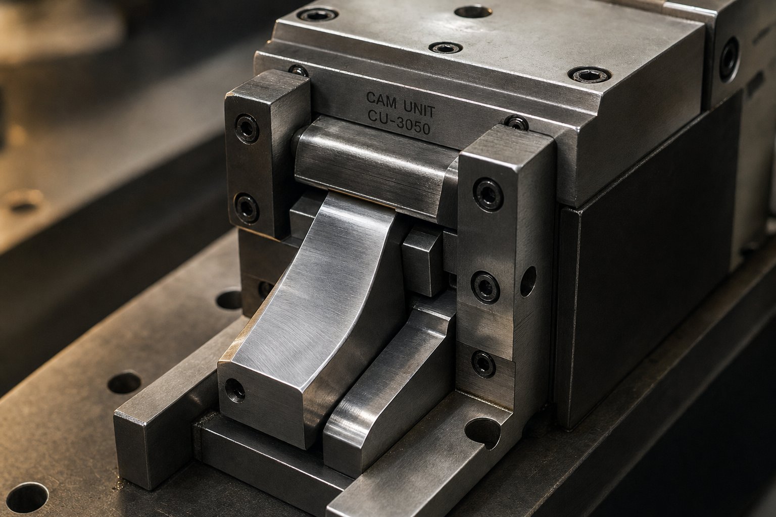
What Cam Units Do in Stamping Dies and Why Quality Matters
When a stamped part needs a hole on its sidewall, a flange formed at an angle, or a trim cut perpendicular to the press stroke, the vertical motion of the ram alone cannot get the job done. That is where cam units come in. These mechanical assemblies live inside the die and redirect the press's downward force into horizontal or angular motion, making otherwise impossible operations routine.
What a Cam Unit Does Inside a Stamping Die
So what is a cam unit in a stamping die? Think of it as a motion translator. The press ram moves straight down, but the cam unit converts that energy into a controlled lateral stroke. This allows punches, form steels, and trim blades to engage the workpiece from the side or at a compound angle rather than from directly above.
A cam unit is a self-contained mechanical assembly integrated into a stamping die that converts the vertical force and motion of the press ram into horizontal or angular force and motion, enabling piercing, forming, and trimming operations that cannot be performed in the press stroke direction alone.
In a progressive die, you might find multiple cam units working at different stations, each performing a distinct operation: one punching a lateral hole, another trimming a flange edge, a third forming a tab outward. The cam unit function in a progressive die is to expand what a single press stroke can accomplish without requiring secondary operations or additional equipment.
Why Cam Units Are Critical to Die Performance
Here is where quality enters the conversation. Every time the press cycles, the cam unit's driver, slide, and retainer must interact with micron-level consistency. Any play, deflection, or misalignment translates directly into dimensional variation on the stamped part. A cam unit with loose fits or soft contact surfaces introduces backlash that accumulates over thousands of cycles, gradually pushing part dimensions out of tolerance.
Rigidity matters just as much. During a piercing operation, the slide must resist the reaction force of the punch breaking through sheet metal without flexing. If the unit deflects even slightly, hole position drifts and burr conditions worsen. In short, how cam units work in metal stamping determines not just whether a feature can be produced, but whether it can be produced consistently across a full production run.
For die designers and tooling engineers specifying cam units for new projects, the purpose of cam units in die design goes beyond simple motion conversion. These components set the ceiling on achievable part accuracy. The sections ahead break down exactly how that precision is engineered, what separates a premium unit from a commodity one, and how to match configurations to specific stamping applications.
How Cam Units Convert Press Force Into Angular Motion
The concept sounds straightforward: vertical force goes in, lateral motion comes out. But the mechanics inside a cam unit are more deliberate than a simple wedge. Understanding how a cam driver converts vertical force to horizontal motion helps you appreciate why tolerances, material choices, and return mechanisms matter so much when specifying units for demanding applications.
How Vertical Press Force Becomes Lateral Motion
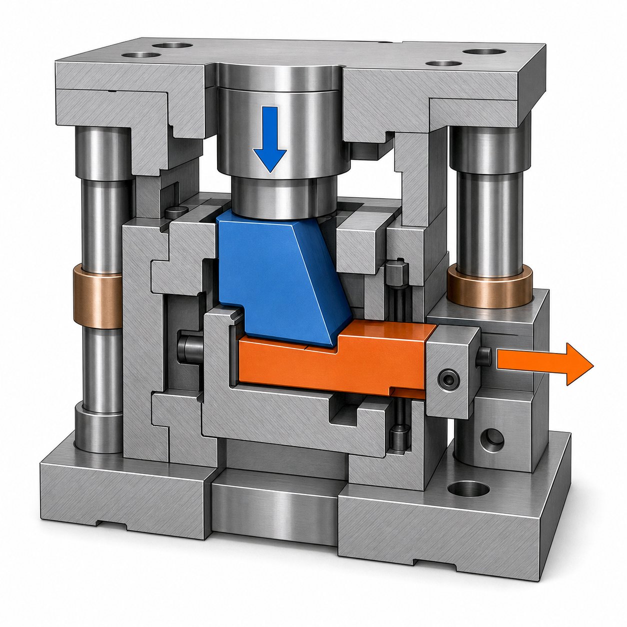
Imagine the upper die descending toward the workpiece. Bolted to that upper die is the driver, a wedge-shaped steel component with a precisely ground angled face. As the press closes, this angled face contacts a matching surface on the slide, which sits in the lower die assembly. The geometry is simple but powerful: the driver's inclined surface pushes against the slide at a designed angle, typically between 15 and 30 degrees from vertical, and the slide has no choice but to travel laterally along its guided path.
The relationship follows basic trigonometry. A driver angle of 15 degrees with 50 mm of vertical press travel produces roughly 13.4 mm of lateral slide stroke, and the force multiplication works in your favor. At that same 15-degree angle, the ideal mechanical advantage sits around 3.7:1, meaning every newton of vertical press force yields nearly four newtons of horizontal working force at the slide. Steeper angles give more stroke per unit of press travel but sacrifice force multiplication, while shallower angles deliver enormous force but minimal stroke.
The slide rides on hardened wear plates that provide low-friction, sacrificial contact surfaces. These plates keep metal-to-metal contact away from the precision-ground slide body itself. Meanwhile, the retainer, essentially the housing that contains the entire assembly, guides the slide along a single axis of travel with minimal clearance. When guide clearance stays below 0.02 mm, the slide tracks true and the punch or form tool it carries hits the workpiece in exactly the same spot every cycle.
Here is the cam unit operating cycle sequence broken into its discrete phases:
- Engage: The press descends and the driver's angled face makes initial contact with the slide's mating surface.
- Drive forward: Continued press travel pushes the slide laterally through its working stroke as the driver wedges deeper.
- Dwell: The press reaches bottom dead center and the slide holds its fully extended position under driver contact pressure.
- Work stroke: While dwelling, the punch or form tool mounted on the slide performs the piercing, trimming, or forming operation on the workpiece.
- Return: The press reverses, the driver disengages, and the slide retracts to its home position via spring force or a positive return mechanism.
The cam slide driver angle geometry explained above reveals why precision grinding of the contact faces is non-negotiable. If the driver angle drifts even half a degree from specification, you'll notice stroke length changes and force distribution shifts that show up as dimensional variation on your stamped parts.
Spring Return Versus Positive Return Mechanisms
Once the driver retracts, something has to pull the slide back to its starting position before the next press cycle begins. This is where the two main return philosophies diverge, and the choice has real consequences for reliability and speed capability.
Spring return is the simpler approach. Compressed coil springs or nitrogen gas springs store energy during the forward stroke and release it to push the slide home when the driver lifts clear. The mechanism is inexpensive, easy to maintain, and perfectly adequate for moderate press speeds and shorter strokes. The limitation? Springs fatigue. Over hundreds of thousands of cycles, spring force degrades gradually, and retraction speed slows. At higher press speeds, there is less time available for the return stroke, and a weakening spring may not fully retract the slide before the next cycle begins. Incomplete retraction means the driver re-engages a slide that is not in position, creating a collision that can damage the driver face, score the wear plates, or crack the slide body.
Positive return takes a fundamentally different approach. Instead of relying on stored spring energy, a mechanical linkage, often a heel block or a captured return driver, physically pulls the slide back as the press opens. The retraction is timed to the press motion itself, so it happens at the same rate and to the same position regardless of cycle count or press speed. There is no degradation over time because the return force is generated mechanically rather than by a consumable spring element.
When comparing a spring return vs positive return cam unit, the tradeoffs come down to application demands:
| Criterion | Spring Return | Positive Return |
|---|---|---|
| Retraction consistency over time | Degrades as springs fatigue | Constant, mechanically driven |
| Maximum press speed suitability | Low to moderate (risk of incomplete return at high SPM) | High speed capable with consistent timing |
| Complexity and cost | Lower initial cost, simpler design | Higher cost, additional components |
| Maintenance interval | Springs require periodic inspection and replacement | Longer intervals, fewer wear items |
| Risk of incomplete retraction | Increases with cycle count and speed | Effectively eliminated |
For high-volume production running at elevated strokes per minute, positive return is often the specified choice precisely because it removes a variable from the equation. You are not betting on spring condition staying adequate across a 500,000-cycle production run. The press motion itself guarantees full retraction every time, which means consistent driver engagement, even wear distribution, and predictable cam timing relative to other die stations.
This reliability distinction is one reason why positive return mechanisms appear so frequently in high-quality cam units for stamping dies. The upfront cost is higher, but the payoff is reduced risk of timing-related failures and more predictable maintenance scheduling across the life of the die.
Of course, understanding how force converts into motion and how the slide returns is only part of the specification picture. Cam units come in a range of configurations, from compact assemblies squeezed into tight die envelopes to heavy-duty units built for high-tonnage piercing. Matching the right configuration to your specific stamping operation is where the real engineering decisions begin.
Types of Cam Units and When to Specify Each Configuration
Not every cam unit fits every die. The stamping operation, available space, and tonnage requirements all shape which configuration belongs in your tooling. Yet cam unit classification often gets oversimplified into a single catalog page without explaining when each type actually makes sense. Understanding the die-mounted vs aerial cam unit differences, and knowing how standard, heavy-duty, and compact versions compare, gives you a clearer path to specification decisions that hold up in production.
Die-Mounted Versus Aerial Cam Units
The most fundamental distinction among types of cam units for progressive dies is where the assembly lives relative to the die set.
Die-mounted cam units bolt directly into the die shoe, typically the lower shoe, and operate as self-contained assemblies. The driver, slide, retainer, wear plates, and return mechanism are all housed within a single compact package that mounts with standard fasteners and dowel pins. Because everything is contained within the die envelope, die-mounted units travel with the tooling during storage, setup, and changeover. They are the default choice when the operation can be accomplished within the available die space and the required stroke length fits within the unit's rated travel.
Aerial cam units, sometimes called flying cams, take a different approach. The movable cam slide assembly mounts on the upper die shoe and translates up and down with the press ram. This mounting position frees space on the lower shoe for other components like lifters, transfer fingers, or additional stations. Aerial cams are commonly specified when you need to reach difficult areas of the workpiece, when the stroke requirement exceeds what a die-mounted unit can deliver in the available footprint, or when the lower die is too crowded to accommodate a conventional unit.
When do you choose one over the other? Die-mounted units suit most standard lateral piercing, trimming, and forming operations where space allows. Aerial cams earn their place in complex progressive dies with tight station spacing, in applications requiring side piercing on deep-drawn parts, or when bottom-shoe real estate is already consumed by lifters and pilots. The tradeoff is that aerial units add complexity to the upper die assembly and require more careful attention to timing relative to strip progression.
Standard, Heavy-Duty, and Compact Configurations
Within both die-mounted and aerial categories, cam units are further differentiated by their load capacity and physical size. Picking the right class means balancing three variables: how much force the operation demands, how far the slide must travel, and how much room you have in the die.
Standard cam units cover the broadest range of everyday stamping work. They offer moderate tonnage capacity, typical stroke lengths, and a footprint that fits comfortably into most progressive and transfer die layouts. For the majority of piercing and light trimming operations in automotive and appliance stampings, standard units handle the job without over-engineering the solution.
A heavy-duty cam unit for high tonnage stamping is built with thicker body sections, wider wear plate contact areas, and more robust return mechanisms. These units are specified when the operation involves cutting through thicker gauge material, forming high-strength steel, or performing large-perimeter trims that generate significant lateral reaction forces. The added mass and rigidity prevent deflection under load, keeping the slide on track during demanding cuts.
At the other extreme, a compact cam unit for tight die space is engineered with a reduced envelope specifically for dies where station-to-station pitch is narrow or where adjacent tooling leaves minimal clearance. Compact units sacrifice some tonnage capacity and stroke length in exchange for fitting into spaces that standard units simply cannot occupy. They appear frequently in high-density progressive dies producing small, complex parts with multiple lateral features close together.
The following table summarizes how these configurations compare across the criteria that matter during specification:
| Configuration | Typical Tonnage Range | Stroke Length | Relative Footprint | Common Applications |
|---|---|---|---|---|
| Standard | 5 - 30 kN | 10 - 30 mm | Medium | Lateral piercing, light trimming, tab forming |
| Heavy-Duty | 30 - 150+ kN | 15 - 50 mm | Large | Thick-gauge trimming, high-strength steel piercing, large-perimeter cuts |
| Compact | 3 - 15 kN | 5 - 20 mm | Small | Tight-pitch progressive dies, small feature piercing, confined forming |
| Aerial (Flying) | 5 - 50 kN | 10 - 40 mm | Upper-die mounted | Side piercing on deep draws, crowded lower-shoe layouts, multi-angle operations |
Notice that the ranges overlap. A 20 kN piercing operation in a roomy die could use either a standard or compact unit. The decision often comes down to available envelope and how much margin you want for load capacity. Specifying a unit at 80% of its rated tonnage rather than 95% extends service life and maintains tighter slide tracking over time.
Configuration choice also interacts with the quality attributes built into the unit. A compact cam unit with loose tolerances will deflect more readily under load than a precision-built version of the same size, simply because there is less material to resist deformation. That relationship between size, build quality, and performance is exactly why understanding what goes on inside a cam unit, component by component, matters just as much as selecting the right external configuration.
Critical Components Inside a Cam Unit
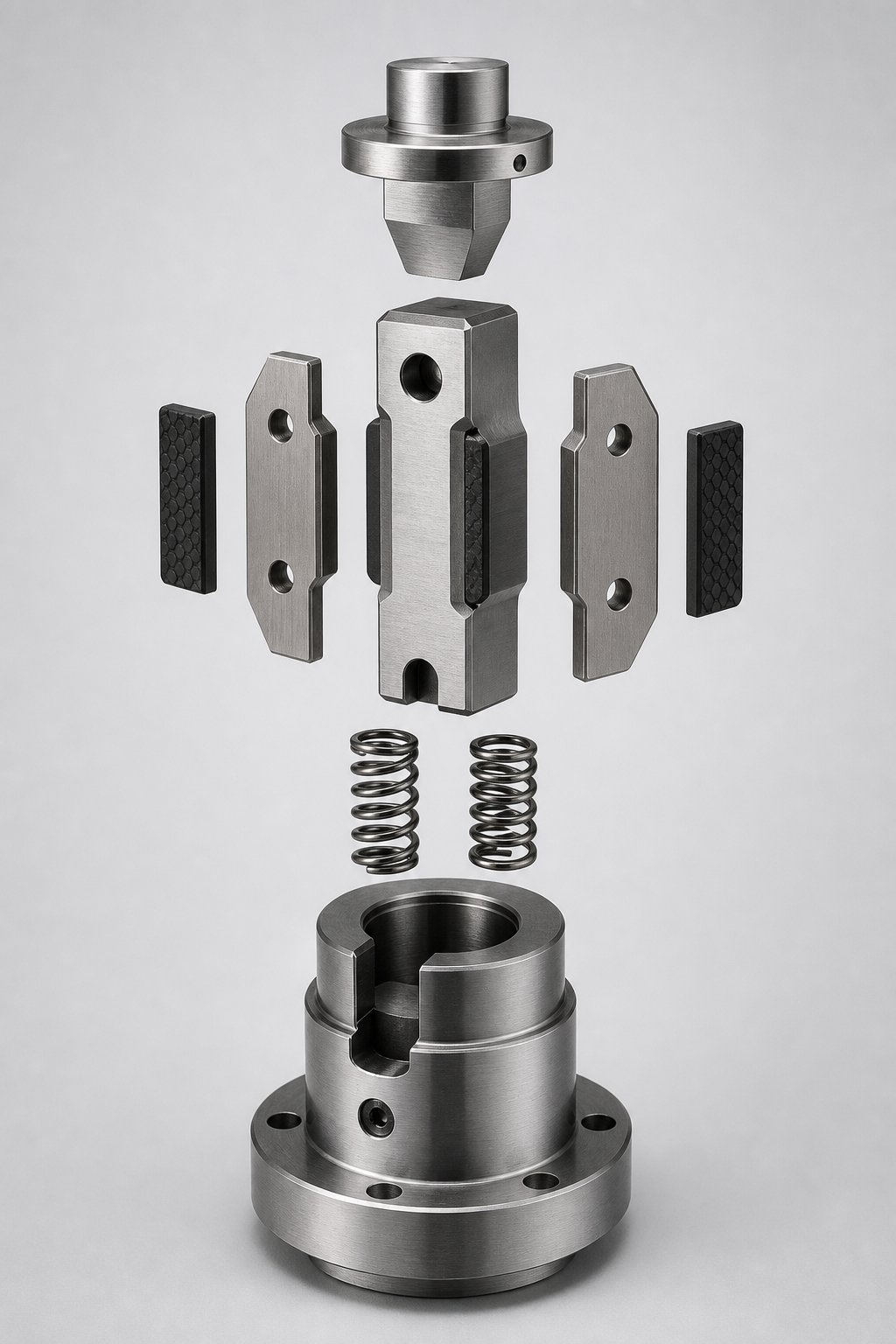
Strip away the outer housing of any cam unit and you find a surprisingly small number of parts. Yet each one carries a specific engineering responsibility, and the quality of every individual component determines whether the assembly delivers micron-level consistency or introduces creeping variation into your stamped parts. Knowing what each piece does, and how they interact, gives you the vocabulary to evaluate suppliers and diagnose problems before they become scrap.
Driver, Slide, and Retainer Explained
These three elements form the structural core of the cam unit. Every other component exists to support, protect, or reset them.
The driver is the wedge-shaped steel element that initiates motion. Its angled face engages a matching surface on the slide as the press closes, converting vertical press travel into lateral force. The driver's contact face is typically precision-ground and hardened to resist deformation under repeated impact loading. If this surface develops wear or waviness, the slide no longer receives a clean, consistent push, and stroke length begins to vary cycle to cycle.
The slide is the work-performing element. It carries the punch, form steel, or trim blade and delivers that tooling into the workpiece at the designed angle. The slide rides within the retainer on guided surfaces and must travel the same path, to the same endpoint, every single stroke. Its body is machined to tight tolerances and hardened to resist both the driving force from above and the reaction force from the workpiece below. Any dimensional change in the slide, whether from wear or deflection, shows up immediately as positional error on the stamped feature.
The retainer is the housing that contains and guides the entire assembly. It provides the reference surfaces that constrain slide travel to a single axis, absorbs mounting forces transmitted to the die shoe, and maintains alignment between the driver path and the slide path. Think of it as the skeleton of the unit. A retainer machined with loose guide clearances allows the slide to drift laterally during the work stroke, introducing the backlash that ruins dimensional repeatability.
How cam unit backlash affects part quality comes down to simple geometry: if the slide can shift even 0.03 mm sideways within its guides, the punch it carries shifts the same amount. Across a production run of 200,000 parts, that play grows as surfaces wear, and your Cpk numbers start sliding in the wrong direction. Precision fit between the cam unit driver, slide, and retainer components is what keeps that backlash near zero at the start of a run and minimizes its growth over time.
Wear Plates, Return Springs, and Graphite Inserts
Beyond the three core structural elements, several supporting components protect the assembly and keep it functioning smoothly over hundreds of thousands of press cycles.
Wear plates, sometimes called cam sheets, are thin hardened plates positioned between the slide and retainer at every contact interface. They serve as sacrificial surfaces, absorbing friction and micro-abrasion so that the precision-ground slide body and retainer guides remain undamaged. When wear plates degrade, you replace them rather than regrinding or replacing the far more expensive slide or retainer. Their material quality, hardness, and surface finish directly impact how long the unit runs before requiring service.
Graphite inserts embedded in the slide or wear plates provide self-lubrication in high-cycle applications where liquid lubrication is impractical or would contaminate the workpiece. As the slide reciprocates, the graphite transfers a thin solid-lubricant film to the mating surface, reducing friction and heat generation without external maintenance. In dies running above 30 strokes per minute continuously, these inserts measurably extend component life.
Return springs, whether coil springs or nitrogen gas springs, store energy during the forward stroke and release it to retract the slide once the driver disengages. In positive-return configurations, a mechanical heel block replaces the spring function entirely. Either way, the return mechanism must deliver consistent retraction force and timing over the life of the unit.
Here is each component with its quality-critical function summarized:
- Driver: Transfers vertical press force to the slide via precision-ground angled contact; hardness and surface integrity determine engagement consistency.
- Slide: Carries working tooling through the lateral stroke; dimensional stability under load dictates feature position accuracy on the stamped part.
- Retainer: Guides and constrains slide travel; guide clearance quality controls backlash and long-term repeatability.
- Wear plates (cam sheets): Provide sacrificial, low-friction contact surfaces; material grade and hardness set the service interval before replacement is needed.
- Graphite inserts: Deliver self-lubrication for high-cycle operation; reduce friction-driven heat and extend slide and wear plate life.
- Return springs or positive return mechanism: Reset the slide to home position; force consistency over time determines retraction reliability at speed.
Of these supporting components, wear plates are almost always the first to show degradation. Scoring, surface roughening, and thickness reduction all indicate that the sacrificial layer is doing its job, but approaching end of life. Engineers who specify premium wear plate materials, typically tool steels hardened above 58 HRC with fine surface finishes, push replacement intervals significantly further than those using standard mild-steel cam sheets.
With the cam unit's internal parts and functions explained, a natural question follows: what specific material choices, hardness levels, and manufacturing tolerances separate a premium assembly from a budget alternative? The answer lies in measurable engineering criteria that any tooling engineer can evaluate before placing an order.
What Makes a Cam Unit High-Quality
You know what is inside a cam unit and how each component contributes to performance. But when two units share the same external dimensions and stroke rating, what justifies one costing significantly more than the other? The difference lives in material selection, heat treatment depth, surface finish quality, and manufacturing tolerances, none of which are visible from the outside. Knowing how to evaluate cam unit quality for stamping dies means looking past catalog specs and into the metallurgy and machining precision that determine real-world service life.
Materials, Hardness, and Surface Treatments That Define Quality
The body and slide of a cam unit endure repeated high-load impact cycles, sometimes millions of them over a die's production life. Standard units often use conventional tool steel with through-hardening to moderate HRC levels. Premium units start with investment-cast or forged alloy steel bodies that offer superior grain structure and fatigue resistance before any heat treatment even begins.
When it comes to high-quality cam unit material and hardness specifications, here is what separates tiers:
- Slide bodies: Case-hardened to 58-62 HRC on contact surfaces while maintaining a tough, ductile core. This combination resists surface wear without becoming brittle under impact loading.
- Drivers: Through-hardened to 56-60 HRC with precision-ground angled faces. The contact surface needs to resist deformation under millions of engagement cycles without developing waviness.
- Retainer guides: Hardened to 54-58 HRC and ground to mirror-finish quality, minimizing friction against the slide and reducing adhesive wear.
- Wear plates: High-speed tool steels or powder metallurgy steels hardened above 60 HRC, providing a sacrificial layer that lasts significantly longer than mild-steel alternatives.
Surface treatments push performance further. Plasma nitriding creates a nitrogen-diffusion layer beneath the surface, increasing hardness and wear resistance without dimensional distortion. Research on case-hardened chromium-manganese steels demonstrates that duplex plasma nitriding followed by DLC coating can increase fatigue life by over 85% under fretting conditions, the exact type of repetitive sliding contact that cam unit surfaces experience. The nitrided layer provides subsurface hardness reinforcement while the DLC coating on cam unit wear surfaces delivers an ultra-hard, low-friction top layer with exceptional chemical stability.
DLC, or diamond-like carbon, coatings are particularly relevant for high-cycle cam applications. These amorphous carbon films combine sp3 (diamond-like) and sp2 (graphite-like) bonding structures, yielding surface hardness values exceeding 1300 HV while maintaining friction coefficients as low as 0.1. For cam unit slides running at 40+ strokes per minute without liquid lubrication, DLC reduces heat generation and adhesive wear on the guide surfaces that determine positional accuracy.
Nitriding alone offers a cost-effective middle ground. The process diffuses nitrogen into the steel substrate at temperatures around 450-550 degrees Celsius, creating a hardened case without the dimensional changes associated with conventional carburizing. For cam units, this means components can be finish-machined first and then nitrided, preserving the precision geometry established during grinding.
Manufacturing Tolerances and Precision Standards
Material quality sets the ceiling for durability. Manufacturing tolerances set the ceiling for accuracy. A slide machined from the finest tool steel still produces inconsistent parts if its guide surfaces are ground to loose specifications.
Cam unit manufacturing tolerance standards vary significantly across quality tiers. Standard-grade units typically hold dimensional tolerances of plus or minus 0.05 mm on critical guide surfaces. This is adequate for many applications, but it allows up to 0.1 mm of total positional variation between the slide and its housing. Premium units tighten that window to plus or minus 0.03 mm or better, cutting allowable variation by 40% and directly improving stamped part dimensional consistency.
Where does that precision come from? Precision grinding using CNC-controlled surface and cylindrical grinders achieves sub-micron repeatability on hardened steel components. CBN (cubic boron nitride) grinding wheels maintain their form when cutting hardened tool steels above 58 HRC, delivering consistent dimensional and geometric tolerances across production batches. Cam unit precision grinding and surface treatment work together here: the component is hardened first, then finish-ground to final dimensions, ensuring that the geometry you measure is the geometry that performs in the die.
Beyond dimensional tolerances, geometric tolerances matter equally. Flatness of the slide's bearing surfaces, parallelism between opposite guide faces, and perpendicularity of the work face relative to the travel axis all influence how cleanly the slide tracks during its stroke. A slide that is dimensionally correct but geometrically skewed will bind, generate uneven wear, and drift off-axis under load.
Surface finish on guide and contact surfaces also separates quality levels. A ground surface with Ra 0.2 micrometers generates less friction and distributes load more evenly than one finished to Ra 0.8 micrometers. Less friction means less heat, less heat means less thermal expansion during continuous running, and less expansion means tighter positional consistency across a production shift.
The following table consolidates these quality indicators into an evaluation framework you can reference when comparing cam unit suppliers:
| Quality Indicator | Standard Grade | Premium Grade | Why It Matters |
|---|---|---|---|
| Dimensional tolerance (guide surfaces) | +/- 0.05 mm | +/- 0.03 mm or tighter | Directly limits achievable stamped part accuracy |
| Slide surface hardness | 50-55 HRC | 58-62 HRC (case-hardened) | Resists wear and maintains geometry over millions of cycles |
| Driver contact face hardness | 52-56 HRC | 56-60 HRC | Prevents deformation under repetitive impact engagement |
| Surface treatment | None or basic nitriding | Plasma nitriding + DLC or advanced nitriding | Extends wear life, reduces friction, improves fatigue resistance |
| Surface finish (Ra) | 0.6 - 0.8 micrometers | 0.1 - 0.3 micrometers | Lower friction, less heat, more uniform load distribution |
| Body material | Conventional tool steel | Investment-cast or forged alloy steel | Superior fatigue resistance and grain structure |
| Expected cycle life before service | 200,000 - 500,000 cycles | 800,000 - 2,000,000+ cycles | Fewer interruptions, lower total maintenance cost |
Use this as your checklist. When a supplier quotes a cam unit, ask about the specific hardness values on the slide and driver, the tolerance class of the guide surfaces, whether any surface treatment is applied, and what surface finish specification the contact areas are ground to. These four data points tell you more about real-world performance than any tonnage rating or stroke length alone.
A cam unit built to premium standards costs more upfront. But when your die runs at 35 strokes per minute producing safety-critical automotive brackets, the difference between 300,000 cycles to first service and 1,200,000 cycles is not academic. It is the difference between two unplanned stoppages per quarter and zero. The quality built into the unit's materials, heat treatment, and machining precision pays its way back in uptime, part consistency, and reduced scrap rates.
These quality attributes do not exist in isolation, though. Their value only materializes when the right cam unit configuration meets the right stamping application. Matching unit type to operation type, tonnage, and available die space is where specification decisions come together into a working die design.
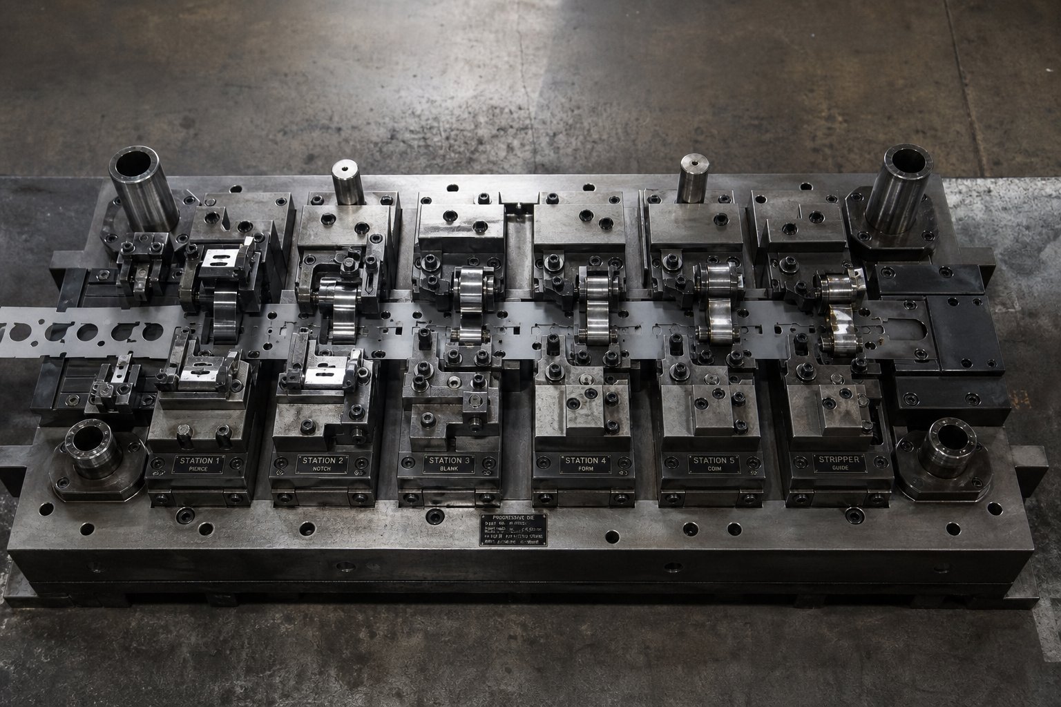
Matching Cam Unit Type to Your Stamping Application
Knowing what quality looks like inside a cam unit is only half the equation. The other half is selecting the right configuration for your specific stamping operation. A perfectly built cam unit still underperforms if it is mismatched to the work it needs to do. Piercing, forming, and trimming each place distinct mechanical demands on the slide, driver, and retainer, and those demands should drive your specification decisions from the start.
Selecting Cam Units for Piercing, Forming, and Trimming Operations
Each stamping operation stresses a cam unit in a different way. Understanding how to select a cam unit for a piercing operation versus a forming or trimming station starts with recognizing what the slide experiences during the work stroke.
Piercing generates a sudden, high-magnitude reaction force the instant the punch breaks through the sheet. The slide must resist this shock load without deflecting laterally, or hole position drifts. Rigidity and minimal backlash are the dominant requirements. A heavy-duty or standard unit with premium guide tolerances handles this best because it keeps the punch on axis through the breakthrough event.
Forming operations behave differently. The slide pushes material into shape progressively, requiring controlled stroke travel and a stable dwell period at full extension while the form steel holds the workpiece against the die cavity. Force builds gradually rather than spiking, but the slide must maintain positional accuracy throughout the entire stroke, not just at a single punch-through moment. Consistent dwell under load is the critical attribute here.
Trimming falls somewhere between. A trim blade shears material along a defined edge, and the cutting force must remain consistent from the start of the cut to the end. If the slide flexes or chatters mid-stroke, the trim edge develops waviness or uneven burr. A cam unit specification for trimming dies should prioritize smooth travel, uniform force delivery, and sufficient tonnage to complete the cut without hesitation.
The following table maps each operation type to the cam configuration, tonnage class, and quality attributes that matter most:
| Operation Type | Recommended Configuration | Tonnage Class | Critical Quality Attributes |
|---|---|---|---|
| Piercing (holes, slots) | Standard or heavy-duty, die-mounted | Medium to high | Maximum rigidity, minimal backlash, shock-load resistance |
| Forming (bends, flanges, embosses) | Standard with positive return | Low to medium | Controlled dwell, consistent stroke endpoint, smooth travel |
| Trimming (edge cuts, perimeter trims) | Heavy-duty or standard, die-mounted | Medium to high | Uniform force throughout cut, chatter-free travel, slide stability |
| Multi-angle piercing | Aerial (flying cam) | Medium | Angular flexibility, upper-die clearance, timing precision |
| Combined pierce and form | Heavy-duty with extended stroke | High | Load capacity for sequential forces, dwell plus breakthrough in one stroke |
Notice that piercing and trimming both lean toward higher tonnage classes, but for different reasons. Piercing needs instantaneous force to shear through material cleanly, while trimming needs sustained force across a longer cutting edge. The cam unit must be sized for the peak demand in each case.
Tonnage, Stroke, and Space Constraints as Selection Criteria
With the operation type guiding your general direction, the practical specification process narrows the choice to a specific unit. This is your cam unit tonnage and stroke selection guide, distilled into a repeatable sequence that works for any lateral die operation.
- Calculate required cam force: Start with the part geometry and material properties. For piercing, multiply the cut perimeter by material thickness and shear strength. For trimming, use the same formula across the trim line length. For forming, estimate the force from bend length, material thickness, and tensile strength. Add a 20-25% safety margin to account for material variation, lubrication inconsistency, and tool wear over time.
- Determine stroke length: Measure the feature depth that the punch or form steel must travel to complete the operation, then add clearance for approach distance (typically 3-5 mm before contact) and overtravel if applicable. The total becomes your minimum required cam stroke.
- Verify die space envelope: Measure the available pocket in the die shoe where the cam unit will mount. Account for adjacent tooling, stripper clearances, and any lifter or pilot mechanisms nearby. The unit's retainer dimensions plus any required mounting clearance must fit within this envelope without interference.
- Check press timing compatibility: Confirm that the available press stroke provides enough driver engagement travel to produce the required cam stroke at the designed driver angle. If the press bottoms out before the driver fully engages, the slide will not reach full travel.
- Evaluate return mechanism suitability: For press speeds above 25-30 strokes per minute, assess whether a spring return can reliably retract the slide within the available time window. If not, specify positive return.
- Confirm tonnage margin: Select a unit rated for at least 125% of your calculated force requirement. Running a cam unit at or near its maximum rating accelerates wear and reduces the service interval between maintenance events.
Choosing cam unit size for die space constraints often involves iterating between steps three and six. You may find that the unit with adequate tonnage is too large for the available space, or that the compact unit that fits lacks sufficient force capacity. This is where configuration tradeoffs become real engineering decisions rather than catalog selections.
In complex die projects, particularly those with multiple cam stations, tight clearances, or unusual material flow patterns, standard catalog units sometimes cannot satisfy every constraint simultaneously. Custom integration becomes necessary when the stamping operation demands a cam envelope, stroke, or tonnage combination that falls outside standard offerings. For design-heavy projects involving die structure, component interaction, clearance optimization, and material flow, working with an engineering partner who understands the full die context, not just the cam unit in isolation, prevents expensive redesign cycles. Tooling engineers evaluating custom cam unit integration within complex die structures can consult resources like YICHEN's stamping die solutions, where die design expertise extends across structure, components, clearance, and material flow considerations that all interact with cam unit selection.
Regardless of whether you end up with a catalog unit or a custom solution, the specification sequence above keeps the decision grounded in measurable criteria. Force, stroke, and space are quantifiable. When you anchor your selection to those numbers rather than habit or brand familiarity, the cam unit you install has the best chance of performing reliably from the first hit to the millionth.
Getting the right unit into the die is only the beginning, though. How that unit gets mounted, aligned, and verified during die build determines whether the precision engineered into its components actually translates to precision on the shop floor.
Installation and Alignment Best Practices for Cam Units
A cam unit built to premium tolerances and hardened to exacting specifications still fails if it is installed poorly. The precision ground into those components during manufacturing only translates to precision on the press if the mounting procedure preserves every geometric relationship the designer intended. Yet installation guidance is rarely discussed in detail. Die makers often rely on tribal knowledge passed between toolroom veterans, and when that knowledge has gaps, the consequences show up as premature wear, inconsistent part dimensions, and mysterious timing issues that resist diagnosis.
The cam unit installation alignment procedure matters because even small errors compound under repetitive loading. A driver that contacts the slide 0.05 mm off-center on the first stroke contacts it 0.05 mm off-center on every stroke, and that one-sided loading pattern accelerates wear on one side of the guide surfaces while the other side runs unloaded. Over 500,000 cycles, what started as a subtle misalignment becomes a measurable clearance problem.
Mounting Procedures and Alignment Requirements
Proper cam unit mounting follows a deliberate sequence. Rushing through it or skipping verification steps invites problems that only reveal themselves after production has started and downtime becomes expensive.
Bolt torque and sequence. Cam unit retainers mount to the die shoe with precision socket head cap screws, typically four to eight depending on unit size. Tightening these fasteners follows a cross-pattern sequence, similar to torquing a cylinder head, to distribute clamping force evenly across the retainer base. Uneven bolt torque distorts the retainer body microscopically, pinching the slide guides on one side and opening clearance on the other. Torque values should follow the cam unit manufacturer's specification, usually in the range of 40-80 Nm for standard units, and a calibrated torque wrench is non-negotiable.
Dowel pin registration. Bolts clamp the unit in place, but dowel pins establish repeatable position. Two precision dowel pins, pressed into reamed holes in both the retainer base and the die shoe, lock the cam unit's X-Y position so that it returns to exactly the same location every time the die is disassembled and reassembled for maintenance. Without dowel pins, the unit shifts slightly during each reinstallation, and the driver-to-slide alignment changes each time. Reamed holes should be machined to H7 tolerance with the cam unit trial-fitted and verified before final pinning.
Shimming for driver engagement height. The cam unit driver engagement height adjustment is one of the most overlooked steps in the build process. The driver, mounted on the upper die, must contact the slide's mating surface at precisely the correct point in the press stroke. If engagement begins too early, the slide reaches full travel before bottom dead center and dwells under excessive compression. If engagement begins too late, the slide may not reach full stroke before the press reverses, resulting in an incomplete work operation.
Shimming accomplishes this adjustment. Precision ground shim plates placed between the driver mounting surface and the upper die shoe raise or lower the driver's starting position by controlled increments, typically available in 0.1 mm steps. The target is to achieve full slide travel exactly at or just before bottom dead center, with 1-2 mm of overtravel built into the driver geometry to ensure the slide reaches its endpoint without relying on the last fraction of press stroke.
Misalignment between the driver and slide is the single most common source of premature cam unit failure. When the driver's angled face does not meet the slide's mating surface squarely, load concentrates on one edge rather than distributing across the full contact width. That edge loading generates localized heat, accelerates surface wear, and can eventually chip hardened contact faces. The remedy is careful alignment verification during die build: blue the driver contact face, close the die slowly by hand, and inspect the contact pattern on the slide. Full, even contact across the width confirms proper alignment. A pattern biased to one side indicates the driver or slide needs repositioning.
Common Setup Mistakes That Compromise Cam Unit Performance
Even experienced die makers occasionally fall into setup errors that degrade cam unit performance. These are the common cam unit setup mistakes in stamping dies that account for the majority of premature service calls:
- Insufficient clearance between cam unit and adjacent die components. Cam units generate heat during operation and expand slightly. If neighboring punches, lifters, or stripper plates are positioned too close, thermal growth creates interference. The slide may bind partway through its stroke or the retainer housing may contact adjacent tooling, transmitting vibration that accelerates wear. Maintain a minimum of 2-3 mm clearance on all sides of the cam unit envelope, and verify clearance dynamically by running the press at operating speed and checking for witness marks.
- Incorrect preload on return springs. Return springs must be preloaded to a specific compressed length at installation so they deliver adequate retraction force from the very first stroke. Under-preloaded springs allow the slide to creep forward during the return phase, especially at higher press speeds. Over-preloaded springs add unnecessary resistance to the forward stroke, increasing driver wear and reducing available working force at the slide. Follow the manufacturer's specified free length and installed length precisely, and verify with a caliper before closing the die.
- Driver engagement angle mismatch. The driver angle and the slide's mating surface angle must be identical. If the die was built with a replacement driver that does not exactly match the original specification, or if the driver has been reground at a slightly different angle, the engagement geometry changes. Even a half-degree mismatch creates a line contact instead of full-face contact, concentrating stress and accelerating surface degradation. Always verify the included angle of replacement drivers with a precision protractor or sine bar before installation.
- Neglecting to verify cam timing relative to other die stations. In a progressive die with multiple cam units or cam-actuated operations adjacent to conventional vertical stations, timing matters. If one cam unit's forward stroke overlaps with the strip lift cycle, the slide can collide with the strip or interfere with pilot engagement. Similarly, if two cam units on opposite sides of the strip fire at slightly different moments, asymmetric forces can shift the strip off-center. Timing verification requires slow-cycling the press through its full stroke and observing the sequence of events at each station. Any interference or overlap demands reshimming or adjusting driver engagement points.
The consequences of these errors range from annoying to catastrophic. Uneven wear shortens service intervals and introduces progressive dimensional drift in stamped parts. Incomplete stroke means features are not fully formed or holes are not cleanly pierced, generating scrap. Timing interference can crash tooling components together, potentially destroying punches, cams, or the die itself in a single stroke.
Verification through test cycling. The most reliable way to confirm correct installation is to measure actual slide travel during test cycling and compare it against the unit's specification. Place a dial indicator or LVDT sensor against the slide face, cycle the press slowly through several complete strokes, and record the total travel distance. It should match the rated stroke within 0.05 mm. If travel falls short, the driver engagement height needs adjustment. If travel varies stroke to stroke, look for loose mounting bolts, insufficient dowel pin engagement, or foreign material in the slide guides.
Knowing how to verify cam unit timing in a progressive die extends this same indicator-based approach to the time domain. Mount indicators on multiple cam stations simultaneously, cycle the press at slow speed, and verify that each unit reaches full extension at the correct crank angle relative to bottom dead center. Document these timing values during initial build so they serve as a baseline for future maintenance comparisons.
Proper installation is a one-time investment of attention that pays dividends across the entire production run. But even a perfectly installed cam unit eventually wears. Recognizing when wear has progressed far enough to affect part quality, and understanding how initial quality choices influence how long that takes, connects installation discipline to the broader question of lifecycle cost.
Maintenance, Lifecycle, and Total Cost of Ownership
A cam unit that was perfectly installed six months ago does not stay perfect forever. Every press stroke generates friction, heat, and micro-abrasion across the slide guides, wear plates, and driver contact faces. The question is not whether a cam unit will eventually need service, but how long it runs before degradation affects your stamped parts, and how much that interval costs you in downtime and replacement components over the life of the die.
Wear Indicators and Service Life Expectations
Catching a cam unit on its way out before it produces scrap starts with recognizing the observable signs of deterioration. You do not need exotic instrumentation for most of these checks, just disciplined inspection routines and an understanding of what normal looks like versus what signals trouble.
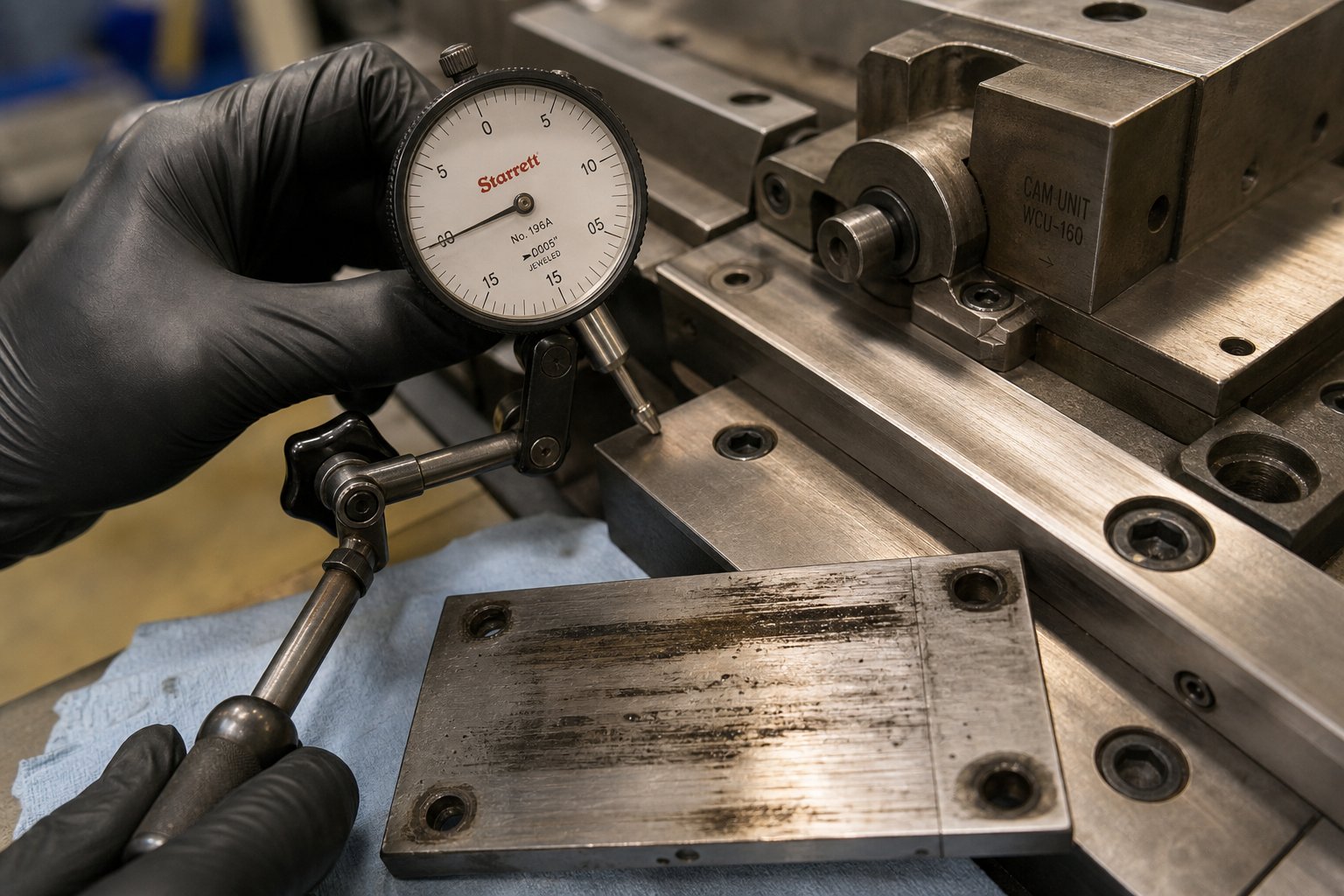
Increased backlash in the slide. This is often the earliest measurable symptom. As guide surfaces and wear plates erode, the clearance between slide and retainer grows. What started as 0.01 mm of total play at installation may creep to 0.05 mm or beyond after several hundred thousand cycles. Cam unit backlash measurement and inspection is straightforward: mount a dial indicator against the slide face perpendicular to its travel axis, apply light lateral pressure, and measure the total deflection. Any value exceeding the manufacturer's allowable play specification means the unit is due for wear plate replacement or guide surface reconditioning.
Visible scoring on wear plates. Pull the cam unit during a scheduled die maintenance event and examine the wear plate surfaces under good lighting. Light, uniform polishing is normal and indicates healthy break-in. Deep grooves, directional scratches, or localized material removal indicate contamination ingress, lubrication failure, or misalignment that is concentrating load on a narrow band. Knowing when to replace cam unit wear plates comes down to surface condition and measurable thickness loss. If the plate has worn more than 0.03-0.05 mm from its original thickness, or if scoring is deep enough to catch a fingernail, replacement is overdue.
Inconsistent part dimensions from the affected station. When a cam-operated feature starts drifting out of tolerance, or when Cpk values at that station decline over a production run without any tooling adjustment, the cam unit is a prime suspect. Positional variation on pierced holes or trimmed edges often traces back to growing backlash or a slide that no longer reaches its full endpoint consistently.
Spring force degradation. For spring-return units, retraction force weakens over time. A simple check is to measure slide return speed or position at a fixed crank angle during slow cycling. If the slide no longer reaches its home position by the expected crank angle, or if return feels sluggish compared to initial setup records, the springs need replacement. Nitrogen gas springs lose pressure gradually and should be checked with a gauge at scheduled intervals.
A well-defined cam unit maintenance schedule for high-volume stamping ties these inspections to cycle count milestones rather than calendar dates. A die running at 30 strokes per minute, two shifts per day, accumulates roughly 250,000 cycles per month. A premium unit with case-hardened slides, DLC-coated wear surfaces, and precision-ground guides might run 1.5 to 2 million cycles before backlash exceeds tolerance. A standard-grade unit under the same conditions may need service at 300,000 to 500,000 cycles. That difference, four to six times the service interval, is where initial quality investment pays its way back in reduced maintenance events and fewer unplanned stops.
Lifecycle Planning and When to Specify Premium Cam Units
The total cost of ownership for premium cam units extends well beyond the purchase price. It includes every wear plate replacement, every hour of press downtime for cam service, every batch of scrap generated when a degraded unit pushes parts out of spec before anyone catches it. When you calculate these costs across a die's full production life, the arithmetic often favors the higher-quality unit by a wide margin.
Consider a concrete example. A standard cam unit priced at $800 requires service every 400,000 cycles. A premium equivalent at $1,400 runs 1,200,000 cycles between services. Over a 3-million-cycle production program, the standard unit needs seven service events while the premium unit needs two. Factor in $500 per service event for parts and labor, plus $2,000 per hour of lost production during each maintenance stop, and the premium unit saves thousands of dollars despite costing more upfront.
Not every application justifies the premium specification. The scenarios where investing in high-quality cam units delivers measurable return are specific and identifiable:
- High-volume production runs: Programs exceeding 500,000 parts per year accumulate cycles fast enough that service interval differences translate directly into fewer production interruptions and lower maintenance labor costs.
- Tight-tolerance parts: When stamped feature tolerances sit at plus or minus 0.1 mm or tighter, the slower backlash growth rate of premium units maintains Cpk targets longer without mid-run adjustments or cam unit service.
- Safety-critical components: Automotive structural parts, airbag housings, and brake system stampings carry quality requirements where dimensional drift is not just inconvenient but potentially dangerous. Premium cam units reduce the probability of out-of-spec parts reaching assembly.
- Applications where unplanned downtime is costly: Just-in-time supply chains with contractual delivery penalties, or press lines feeding downstream assembly operations with no buffer inventory, cannot absorb surprise maintenance stops. Longer service intervals mean more predictable scheduling.
- Multi-cam progressive dies: Dies with four or more cam stations multiply the maintenance frequency problem. If each standard unit needs service at different cycle counts, the die comes out of the press repeatedly. Premium units across all stations synchronize service intervals and reduce total die pulls per year.
For engineers evaluating cam unit specifications within the broader context of die design, the interaction between cam unit quality and surrounding die components matters. Lifter timing, punch sharpness, burr direction, and material flow patterns all influence how hard the cam unit works during each cycle. A die with marginal clearances or poorly controlled strip feed places additional stress on the cam, shortening even a premium unit's service life. This holistic view is where working with a die design partner who understands the complete system delivers value beyond component selection alone. YICHEN's custom stamping die solutions address exactly this integration challenge, combining expertise in die structure, components, punches, lifters, burr control, and clearance into designs where cam unit longevity is optimized alongside overall die performance targets rather than treated as an isolated specification.
The cam unit wear indicators and service life expectations outlined above give you a practical monitoring framework. Pair that with quality-driven specification decisions at the design stage, and you build dies where cam maintenance is predictable, infrequent, and never the reason production stops unexpectedly. That predictability, more than any single technical feature, is what makes high-quality cam units for stamping dies worth their cost.
Frequently Asked Questions About Cam Units for Stamping Dies
1. What is a cam unit in a stamping die and what does it do?
A cam unit is a self-contained mechanical assembly that converts the vertical force of a press ram into horizontal or angular motion. This allows stamping dies to perform piercing, forming, and trimming operations at angles that the press stroke alone cannot reach. Inside, a wedge-shaped driver engages a guided slide during press closure, pushing it laterally so that mounted punches or form tools can work on sidewalls, flanges, or angled features of the workpiece.
2. How do I choose between spring return and positive return cam units?
Spring return units are simpler and less expensive, suitable for moderate press speeds and shorter strokes. However, springs fatigue over time and may not fully retract the slide at higher speeds. Positive return units use a mechanical linkage tied to press motion, guaranteeing full retraction every cycle regardless of speed or cycle count. For high-volume production above 25-30 strokes per minute, or when consistent timing is critical, positive return eliminates the risk of incomplete retraction and reduces unplanned maintenance.
3. What quality indicators should I check when comparing cam unit suppliers?
Focus on four measurable criteria: slide and driver hardness values (premium units achieve 58-62 HRC on case-hardened slides), guide surface tolerances (premium grade holds plus or minus 0.03 mm versus 0.05 mm standard), surface treatments such as plasma nitriding or DLC coatings that extend wear life, and surface finish specifications on contact areas (Ra 0.2 micrometers versus 0.8 for standard). These data points predict real-world cycle life and dimensional consistency far better than tonnage ratings alone.
4. How often should cam units be inspected and serviced in high-volume stamping?
Service intervals should be tied to cycle counts rather than calendar dates. Standard-grade cam units typically need service at 300,000 to 500,000 cycles, while premium units with DLC coatings and precision-ground guides can run 1.5 to 2 million cycles between services. Key inspection points include measuring slide backlash with a dial indicator, examining wear plate surfaces for scoring or thickness loss, checking return spring force, and monitoring stamped part dimensional trends from cam-operated stations.
5. When is it worth investing in premium cam units over standard ones?
Premium cam units deliver measurable returns in specific scenarios: production runs exceeding 500,000 parts per year, tight-tolerance features at plus or minus 0.1 mm or below, safety-critical automotive or structural components, applications where unplanned downtime carries contractual penalties, and multi-cam progressive dies where synchronizing service intervals reduces total die pulls. Engineers working on design-heavy projects with complex die structures can consult partners like YICHEN (yichen-group.com/stamping-die/) who integrate cam unit quality within holistic die design covering structure, clearance, and material flow.


