


What Is a Stamping Die and Why Every Component Matters
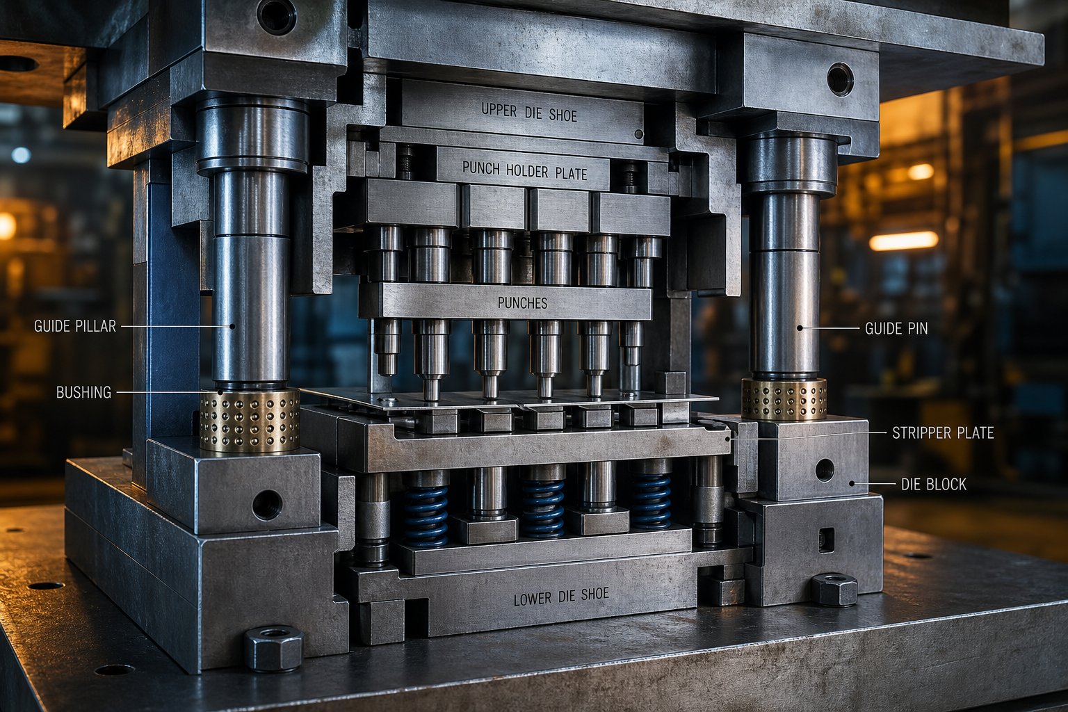
When you ask what are dies in the context of sheet metal manufacturing, the answer comes down to precision and force. A stamping die is a custom-built tool installed in a press that transforms flat sheet metal into finished parts through cutting, forming, or a combination of both. It consists of two halves: an upper section attached to the press ram and a lower section mounted on the press bed. When the press cycles, these halves close together with enormous force, and the shaped steel sections between them shear or bend the material into its final geometry.
What a Stamping Die Actually Does
So what is a die used for in practical terms? A die is used to produce everything from tiny electrical connectors to full automobile body panels. The tool's cutting and forming sections, typically made from hardened tool steel or carbide, shape the workpiece while the surrounding structure absorbs tonnage and maintains alignment. Stamping dies can cycle as fast as 1,500 strokes per minute, and each stroke produces a finished or partially finished part. This combination of speed and precision makes stamping dies the backbone of high-volume metal manufacturing.
Why Understanding Individual Components Matters
Most references treat the parts of a stamping die as a flat list of vocabulary terms. That approach misses the point. These components form interconnected subsystems, and each one influences the others during every press stroke. When a tooling engineer understands how those subsystems relate, diagnosing defects becomes faster, specifying replacement parts becomes more precise, and communication with die builders gets clearer. Component-level knowledge connects directly to part quality, maintenance scheduling, and cost control.
Every stamping defect traces back to a specific component condition. Identify the component, and you identify the fix.
The sections that follow break stamping dies into five functional subsystems rather than offering a parts catalog. This systems-level approach reveals how wear in one area cascades into failures elsewhere, and why certain components demand attention long before others show visible damage.
How Die Components Organize Into Functional Subsystems
A stamping die can contain dozens of individual parts, but listing them randomly does not help you troubleshoot a burr problem at 2 a.m. or explain to a die builder exactly where a failure originated. A more practical approach groups stamping die components into five functional subsystems based on what they actually do during a press cycle. This framework gives you a mental model for connecting any defect on a stamped part back to the responsible system, and then down to the specific component within it.
Five Functional Subsystems of a Die
Every die assembly, regardless of size or complexity, relies on these five working groups. Each subsystem has a distinct job during the press stroke, and each depends on the others performing correctly.
- Structural system - Absorbs press tonnage, maintains rigidity, and provides mounting surfaces for all other die components. Key parts: die shoes, backup plates, fasteners, and dowel pins.
- Cutting system - Performs shearing, blanking, piercing, and notching operations that separate material. Key parts: punches, die blocks, and sectional cutting inserts.
- Guiding system - Maintains precise alignment between upper and lower die halves and registers the strip at each station. Key parts: guide pins, bushings, pilot pins, and heel blocks.
- Stripping system - Holds material flat during cutting, then removes the strip from punches on the upstroke. Key parts: stripper plates, die springs, nitrogen cylinders, and pressure pads.
- Ejection system - Removes finished parts and slugs from die cavities while controlling strip movement between strokes. Key parts: knockout pins, shedders, lifters, and bypass notches.
You will notice that stamping components from industry catalogs often appear in more than one grouping depending on the die design. A pilot pin, for example, serves the guiding system but is physically mounted in the cutting system's punch plate. The point is function, not physical location.
How These Systems Interact During a Press Stroke
Imagine a single press cycle in a progressive die. The ram starts at top dead center, descends, performs work, and returns. During that fraction of a second, all five subsystems activate in a precise sequence. No component works in isolation. A worn bushing in the guiding system causes misalignment that accelerates punch wear in the cutting system. A broken spring in the stripping system lets a slug ride back up on a punch tip, jamming the ejection system on the next stroke.
The table below maps each phase of the press stroke to the active subsystem and the critical die components involved:
| Press Stroke Phase | Active Subsystem | Key Components |
|---|---|---|
| Strip advances to next station | Ejection | Lifters, feed rails, bypass notches |
| Pilot pins enter strip holes | Guiding | Pilot pins, guide pins, bushings |
| Stripper contacts material | Stripping | Stripper plate, springs, pressure pads |
| Punches cut or form material | Cutting | Punches, die blocks, cutting inserts |
| Ram reaches bottom dead center | Structural | Die shoes, backup plates, heel blocks |
| Ram retracts, strip pulled off punches | Stripping | Stripper plate, springs |
| Slugs and parts ejected from cavities | Ejection | Knockout pins, shedders |
This sequence repeats hundreds or thousands of times per minute. Each handoff between subsystems creates a potential failure point. When you approach diagnostics through this lens, a quality problem stops being mysterious. You trace the defect to the stroke phase where it originates, identify the active subsystem, and narrow down to the specific component that needs attention.
With this framework in place, the logical starting point for a deeper look is the structural system, the foundation that every other subsystem literally bolts onto.
Die Shoes and the Structural Foundation
Every cutting insert, guide pin, and stripper plate in a stamping die bolts onto something. That something is the structural system, and its job is deceptively simple: absorb tonnage, stay flat, and keep everything exactly where the die designer put it. Get the foundation wrong and nothing mounted to it can perform correctly, regardless of how precisely those components were ground or wire-cut.
Upper and Lower Die Shoes
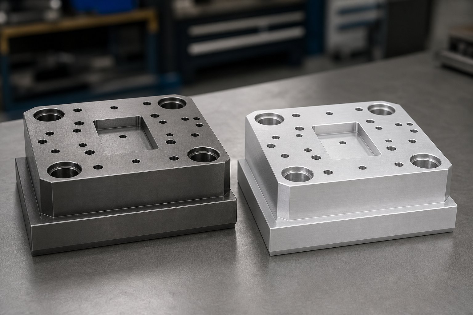
Die shoes are thick, precision-ground plates that form the skeleton of the entire die assembly. The lower die shoe mounts to the press bed, while the upper die shoe attaches to the ram. Together they provide stable, parallel surfaces for locating and securing all working components. Think of them as the chassis that every other subsystem rides on.
Most die shoes are made from steel, typically medium-carbon or alloy grades that offer rigidity and wear resistance under repeated loading. Aluminum is the alternative, and it brings real advantages. As The Fabricator notes, aluminum weighs one-third as much as steel, machines quickly, and absorbs shock well, making it a strong choice for blanking dies where impact forces are high. Special alloys can give aluminum greater compressive strength than low-carbon steel, though it still wears faster under sustained sliding contact.
What determines how thick a die shoe needs to be? Three factors dominate: press tonnage applied during the operation, the unsupported span between mounting points, and how punch loads distribute across the plate. A coining die that squeezes metal under massive compressive force requires a much thicker shoe than a simple bending die where loads concentrate over a small area. Undersized shoes deflect under load, and that deflection shows up immediately as dimensional variation in stamped parts.
| Criteria | Steel Die Shoes | Aluminum Die Shoes |
|---|---|---|
| Weight | Heavy (baseline) | Approximately 1/3 of steel |
| Cost | Lower material cost, slower machining | Higher material cost, faster machining |
| Wear Resistance | High, suited for long production runs | Moderate, may require hardcoat in high-wear zones |
| Shock Absorption | Low | High, ideal for blanking applications |
| Typical Application | Progressive dies, high-volume production | Prototype dies, large blanking dies, weight-sensitive setups |
Backup Plates and Load Distribution
Here is a detail most references skip entirely. When a hardened punch drives through sheet metal, it concentrates enormous force over a tiny cross-section. Mount that punch directly into a die shoe, and the repeated impact will peen the shoe surface over time, creating a pocket that allows the punch to shift or sink. The fix is a backup plate, sometimes called a punch retainer plate or die pad plate.
A backup plate sits between the punch heads and the die shoe. Its job is purely mechanical: spread concentrated punch loads over a wider area so the shoe surface stays flat and undamaged. These plates are typically hardened to at least 45 HRC, giving them enough surface hardness to resist peening from high-pressure punch shanks.
When are they necessary? Any time punch cross-sections are small relative to the applied shear force, you need a backup plate. Large-diameter punches with broad heads may mount directly to the shoe without causing damage. Small punches, closely spaced punch clusters, and high-tonnage applications always benefit from that intermediate hardened layer.
Die Sets and Mounting Hardware
A stamping die set is a pre-assembled unit consisting of upper and lower die shoes joined by guide posts. Purchasing metal stamping die sets as standard catalog items gives shops a significant advantage: consistency. The shoes arrive parallel-ground, the guide posts are already pressed in, and the assembly drops into the press with predictable alignment. For shops running frequent die changes, standard die sets reduce setup time and eliminate the variability of building structural assemblies from scratch each time.
Mounting hardware locks everything in place. Socket head cap screws, the most common fastener in stamping dies, secure components to the shoes with high clamping force in a compact footprint. Dowel pins handle location, pressing into reamed holes to position each component within thousandths of an inch. Keys, small precision-ground rectangular blocks seated in milled keyways, provide additional resistance against lateral movement during heavy side-loading operations.
Together, screws hold components down, dowels locate them precisely, and keys prevent them from shifting under load. Lose any one of those three functions and the structural system stops doing its job, which means every subsystem mounted above it starts drifting out of position. That drift is where the guiding system picks up the story, maintaining alignment with a different set of tools entirely.
Punches, Die Blocks, and the Science of Clearance
Structural alignment only matters if the components doing the actual cutting are sharp, correctly paired, and separated by exactly the right gap. The cutting subsystem is where dies and punches interact with the workpiece under shear stress, and it is the first place wear shows up in production. Every hole, slot, notch, and blank profile on a stamped part traces back to this subsystem's condition.
Punches and Their Geometry
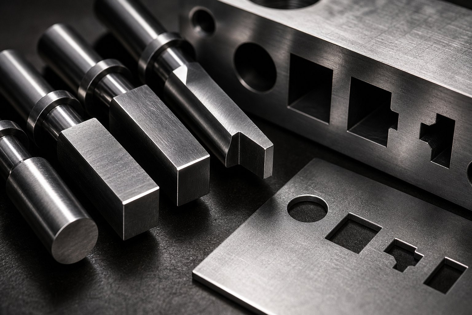
A punch is the male cutting tool that penetrates the sheet metal and forces material through the die opening below. Punch geometry directly determines the cut profile on the finished part. Round punches handle standard holes. Shaped punches produce rectangles, D-cuts, or custom profiles. Notching punches trim edges. Lancing punches cut and bend tabs in a single stroke without fully separating material.
What matters just as much as shape is what the punch is made from. Stamping die punches are typically manufactured from tool steels selected to balance toughness against wear resistance:
- A2 tool steel - Air-hardened, good toughness, moderate wear resistance. Suitable for low-to-medium production runs on mild steel and aluminum.
- D2 tool steel - High carbon, high chromium. Excellent wear resistance for long production runs but more brittle under shock loads.
- M2 high-speed steel - Retains hardness at elevated temperatures. Ideal for high-speed progressive dies where friction heat builds rapidly.
- Carbide (tungsten carbide) - Maximum wear resistance for abrasive materials like stainless steel or silicon steel. Brittle, requires careful alignment and support.
The choice depends on production volume and work material hardness. A shop stamping 5,000 mild steel brackets might run A2 punches economically, while a lamination die cycling millions of silicon steel parts demands carbide to maintain edge quality between sharpening intervals.
Die Blocks and Cutting Inserts
The die block is the mating female component that receives the punch. It provides the cutting edge on the underside of the workpiece and defines the final dimension of the blanked or pierced feature. In a sheet metal punch and die relationship, the die block does not simply provide a hole for the punch to pass through. It provides a precisely profiled opening where material fractures cleanly along shear planes.
For complex profiles or high-wear applications, die builders use sectional inserts rather than machining the entire block. These inserts are individual hardened segments pressed or bolted into the die block body. When a cutting edge wears, you replace only the affected insert rather than regrinding or scrapping the entire block. This approach cuts maintenance cost and reduces downtime significantly.
Wire-EDM profiling has transformed how die openings are manufactured. This process uses an electrically charged wire to cut hardened tool steel with tolerances as tight as +/-0.0001 inches. For tight-tolerance sheet metal punches and dies, wire-EDM allows die builders to profile openings after heat treatment, eliminating distortion concerns that plague conventional machining of hardened materials.
Clearance and Its Effect on Part Quality
Clearance is the gap between the punch cutting edge and the die block cutting edge, measured per side. It is typically expressed as a percentage of material thickness. When a punch descends into a sheet, fracture lines propagate from both the punch edge and the die edge. Proper clearance aligns those fracture planes so they meet cleanly in the middle of the material, producing a smooth shear zone and minimal burr.
Get it wrong in either direction and problems compound quickly. MISUMI's engineering team notes that the standard recommended clearance is around 10% of material thickness per side, though modern practice suggests 11-20% can reduce tooling strain and extend punch life. Insufficient clearance forces the punch to work harder, increases tonnage requirements, and causes premature edge chipping. Excessive clearance allows the material to roll into the die opening before fracturing, producing heavy burrs, rolled edges, and dimensional variation that may require secondary deburring operations.
The table below shows how clearance percentage affects edge quality and burr formation in mild steel at common thicknesses:
| Clearance (% per side) | Resulting Edge Condition | Burr Height Tendency | Typical Application |
|---|---|---|---|
| 3-5% | Clean shear, minimal rollover, high punch load | Low initially, increases rapidly as punch wears | Fine blanking, precision electronics |
| 8-12% | Balanced shear zone and fracture zone, clean break | Minimal under normal conditions | General-purpose stamping, mild steel 0.5-2.0 mm |
| 13-18% | Larger fracture zone, slight rollover at entry | Moderate, acceptable for non-critical edges | Structural parts, thicker stock (2.0-4.0 mm) |
| 20-25% | Significant rollover, rough fracture surface | Heavy burrs likely, secondary deburring required | Only for soft materials or when extended tool life is priority |
Proper clearance is the single most influential factor in controlling burr formation on stamped parts. A metal punches and die pairing that starts with correct clearance will produce consistent edge quality for hundreds of thousands of cycles. The same tooling with clearance set just a few percent off will generate reject parts from the first hit.
Clearance also interacts with material properties. Harder, higher-tensile-strength materials require greater clearance because they resist plastic deformation and fracture more abruptly. Softer materials like copper or aluminum tolerate tighter clearance without excessive punch loading. Every time the work material changes, clearance should be recalculated rather than assumed from the previous job.
Cutting precision depends on more than just sharp edges and correct clearance, though. The punch must enter the die opening in exactly the same position every cycle, which brings the focus to the components responsible for maintaining that alignment under dynamic load.
Guide Pins, Pilot Pins, and Precision Alignment
A punch ground to perfect geometry and paired with optimal clearance will still produce scrap if the upper and lower die halves drift even a few microns out of alignment during the stroke. The guiding subsystem exists to prevent exactly that. Its tooling components maintain repeatable positioning between the die halves through millions of press cycles, and they register the strip material at each station so every operation hits its intended target.
When guiding components wear, the effects compound silently. Parts pass inspection for weeks while bushings gradually loosen, until one morning the burr on station three suddenly doubles in height. Understanding how each element in this subsystem functions, and how it fails, separates reactive troubleshooting from predictive maintenance.
Guide Pins and Bushings
Guide pins, sometimes called guide posts or pillars, are hardened steel cylinders mounted in one die shoe that slide through precision bushings in the opposing shoe. Their sole purpose is to keep the upper and lower halves in exact registration so that cutting and forming clearances remain consistent throughout the stroke. As Art Hedrick of Dieology emphasizes, guide pins are designed to locate die halves precisely, not to compensate for a poorly maintained press.
Two types of guide-post and bushing systems dominate die tooling:
- Plain-bearing (friction) pins - The guide post is slightly smaller than the bushing bore, typically by about 0.0005 inches, creating a small running clearance. Bushings are commonly aluminum bronze, sometimes impregnated with graphite for self-lubrication. Friction pins handle heavy side thrust well because the full cylindrical surface absorbs lateral loads. The tradeoff is higher friction, which limits press speed and makes die separation more difficult.
- Ball-bearing pins - A cage of precision ball bearings rolls between the pin and bushing in a preloaded (negative clearance) condition. This eliminates sliding friction, enables higher press speeds, and simplifies die separation. However, MetalForming Magazine notes that excessive side loads can cause individual ball bearings to dig tracking marks into the guide-post OD or bushing ID, because each ball makes only point contact with the surfaces.
Fit types matter here. The guide pin is press-fit into its home shoe, locking it permanently in position. The bushing bore provides a slip fit (or preloaded rolling fit for ball-bearing types) so the opposing shoe can travel freely along the pin axis. When bushing wear opens up that running clearance beyond design limits, the upper die half gains freedom to shift laterally, and you will see it as part-to-part dimensional variation.
One critical design detail: the guide bushing should engage the guide post at the working level of the die whenever possible. This loads the pin in shear, its strongest condition, rather than creating a bending moment that causes deflection at the cutting plane.
Pilot Pins and Strip Registration
Guide pins align the die halves to each other, but the strip material also needs precise positioning at every station. That job belongs to pilot pins. These are tapered, bullet-nosed pins mounted in the upper die that enter pre-pierced holes in the strip just before cutting or forming operations begin. Their taper draws the strip into exact position, correcting any feed-length error or lateral drift before the punches engage.
In progressive tooling dies, pilot pins are arguably the most critical alignment feature. The strip indexes through multiple stations, and every operation must register to the same datum holes pierced at station one. If pilot pin diameters are correct relative to pilot hole size, each station adds its feature in perfect relation to the others. Typical pilot pin diameter runs 0.001 to 0.002 inches smaller than the pilot hole to allow entry without deforming the hole edges, while still providing accurate location.
When pilot pins wear, their effective diameter shrinks and the taper rounds off. The strip no longer centers precisely at each station, producing progressive feature drift: hole patterns shift incrementally from station to station, mating features stop aligning, and the finished part fails dimensional inspection. In a high-station progressive machine die, worn pilots can create compound errors that are difficult to trace without methodical station-by-station measurement.
Heel Blocks and Side Guidance
Guide pins handle vertical alignment effectively, but certain operations generate lateral thrust that pins alone cannot fully absorb. Angled trims, cam-driven cuts, and asymmetric forming all push the upper die sideways during the working portion of the stroke. Heel blocks resist these forces.
Heel blocks are hardened wear plates bolted to both die halves, positioned so they engage just before or at the working level. They create a boxed containment that prevents sideways movement under unbalanced loads. Some engineers prefer that guide pins engage first for alignment, then heel blocks absorb lateral thrust during cutting. Others use heel blocks as the primary guidance for large forming dies where ultraprecise alignment is less critical than raw lateral stability.
A key advantage of guide pins over heel blocks is maintainability. Worn bushings swap out for new commercial replacements that work immediately. Worn heel plates require shimming or grinding to restore proper clearance, effectively making them custom components each time they are serviced.
When any element of the guiding subsystem degrades, the symptoms show up on your stamped parts. Here are the most common indicators:
- Uneven burr height around a pierced hole (one side heavier than the other) indicates lateral misalignment between punch and die block caused by worn bushings or deflected guide pins.
- Progressive feature drift across stations in a progressive die signals worn or undersized pilot pins failing to register the strip accurately.
- Scoring or galling marks on guide pins reveal contamination, inadequate lubrication, or excessive side loading that will eventually seize the die.
- Increasing dimensional variation from part to part, especially in tight-tolerance features, points to bushing clearance opening beyond design limits.
- Premature punch edge chipping on one side only indicates the upper die is shifting under load, typically from worn heel blocks or tracking damage on ball-bearing guides.
- Audible clicking or roughness during slow hand-cycling of the die suggests ball-bearing cage damage or foreign material trapped between guide surfaces.
Each of these symptoms traces to a specific guiding component condition. Catching them early, through routine inspection of guide pin surfaces, measurement of bushing clearances, and monitoring of pilot pin diameters, prevents the cascading damage that occurs when misalignment accelerates wear in the cutting and stripping systems simultaneously.
Alignment ensures punches meet die blocks in the right place. Stripping ensures the material releases cleanly once that meeting is over, a function driven by an entirely different set of forces and spring systems that demand their own attention.
Strippers, Springs, and Pressure Systems
Punches cut the material, and guide pins keep everything aligned. But what holds the sheet metal flat against the die surface while that cut happens? And what pulls the strip back off the punches when the ram retracts? Both answers point to the same subsystem: strippers and the spring systems that power them. These press die components rarely get the attention they deserve until something goes wrong, yet they directly control cut quality, slug behavior, and part flatness on every single stroke.
Strippers and Their Dual Role
A stripper serves two functions simultaneously. First, it clamps the sheet metal flat against the lower die surface during cutting, preventing the material from bowing upward around the punch as it penetrates. This improves edge quality, reduces punch deflection, and keeps the workpiece stable during forming. Second, it strips the material off the punch body during withdrawal. Sheet metal naturally collapses around a punch shank during piercing, creating a tight grip that resists separation. The stripper provides the downward force needed to peel the strip free as the punch retracts.
Two fundamental stripper designs exist, and choosing the wrong one for your application causes predictable problems.
Channel strippers (bridge strippers) are fixed plates solid-mounted to the lower die. They are simple, inexpensive, and require almost no maintenance. The strip passes through a channel machined in the plate, and as the punch retracts, the plate physically prevents the strip from traveling upward with it. Sounds straightforward, but as die design expert Art Hedrick emphasizes, bridge strippers do not hold the material down during cutting. The metal is free to bow, shift laterally, and bind between punches. That freedom leads to punch deflection, chipping, and in severe cases, punches being ripped from their retainers during stripping.
Spring-loaded strippers (pressure pads) are plates mounted to the upper die on springs or gas cylinders. They contact and flatten the material before the punches engage, hold it firmly throughout the cut, and continue pressing the strip down as punches withdraw. This eliminates material movement during cutting and provides controlled, consistent stripping force on every stroke. The tradeoff is higher cost, more complex construction, and the ongoing maintenance requirement of spring replacement.
When should you use which? Bridge strippers can work in simple, low-speed dies with minimal piercing and no tight tolerances. For virtually everything else in modern metal stamping tool and die applications, spring-loaded strippers are the standard. The manufacturing cost savings of a bridge stripper rarely outweigh the production risk.
Spring Systems That Drive Stripping Force
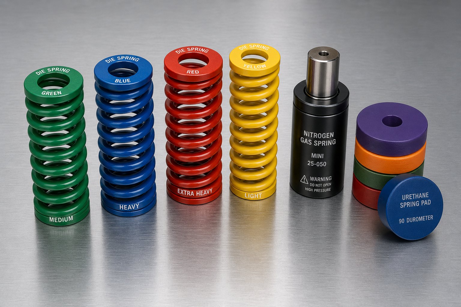
The performance of a spring-loaded stripper depends entirely on what is pushing it. Three primary spring types power stripping systems in stamping dies, and each brings distinct characteristics to the die pressing operation.
Conventional die springs are helical compression springs made from high-strength alloy wire, designed to deliver high force in a compact package. They are color-coded by deflection rate: light load (green), medium load (blue), heavy load (red), and extra-heavy load (yellow). This coding lets maintenance technicians identify spring capacity at a glance without measuring. Die springs handle approximately 30% more load than standard compression springs of the same size and are the most common choice for general-purpose stamping tool and die work.
Nitrogen gas springs use compressed nitrogen contained in a sealed cylinder with a piston rod. They deliver significantly higher force in a smaller package compared to mechanical springs, and they maintain more consistent pressure throughout the stroke because gas compression follows a flatter force curve than coil deflection. They also last longer under sustained cycling. The tradeoff is higher upfront cost and the need for periodic pressure checks. Nitrogen springs make the most sense for complex dies with limited space, heavy-duty loads, or applications requiring uniform pressure across long stripper-pad travel.
Urethane springs are solid elastomeric pads or cylinders that compress under load. They absorb vibration effectively, can be manufactured in custom shapes to fit irregular cavities, and cost less than nitrogen systems. Their limitation is lower fatigue life compared to both mechanical and nitrogen options, and they lose stiffness over time as the material creeps under repeated compression.
Selecting the right spring type requires balancing force density, lifespan, available space, and budget. The table below compares these three options across the criteria that matter most on the shop floor:
| Criteria | Conventional Die Springs | Nitrogen Gas Springs | Urethane Springs |
|---|---|---|---|
| Force Density | Moderate, multiple springs often needed | High, fewer units required for same force | Low to moderate, depends on durometer |
| Fatigue Life | Moderate (may need frequent replacement at high speeds) | High (engineered for millions of cycles) | Low to moderate (creep degrades performance over time) |
| Force Consistency | Varies with deflection (rising rate curve) | Nearly constant throughout stroke | Progressive, increases with compression |
| Cost | Low upfront | High upfront, more economical long-term | Low |
| Space Requirement | Requires deep pockets, multiple units per pad | Compact, single unit replaces several coil springs | Flexible shapes fit irregular spaces |
| Typical Application | General-purpose dies, high-speed flat parts | Complex dies, heavy loads, long pad travel | Light-duty stripping, vibration-sensitive dies |
Spring preload and travel are two parameters that determine whether stripping actually works. Preload is the force the spring exerts at its installed height before the die closes. Too little preload and the stripper cannot flatten material before punch contact. Travel is the distance the spring compresses during the stroke. If spring travel is shorter than the working stroke, the spring bottoms out, creating a hard stop that can crack retainers or damage the die shoe. A properly designed stripper system compresses to no more than 75% of the spring's available travel at full stroke.
What Happens When Stripping Fails
Stripping failures rarely announce themselves with a loud crash. They creep in gradually as springs fatigue, lose preload, or break one at a time in a multi-spring arrangement. The die keeps running, but part quality degrades in specific, traceable ways.
Slug pulling is the most immediate consequence. When stripping force drops below the threshold needed to hold material against the lower die during punch withdrawal, the vacuum seal between slug and punch face wins. The slug rides back up on the punch and falls onto the strip or into the die cavity. A single pulled slug carried through a progressive die can damage every station in the tool, crippling production and creating expensive repair bills. Insufficient stripping force is one of the primary contributors to this problem, alongside large cutting clearances and vacuum pockets.
Material lifting between stations occurs when the strip is not held firmly enough during punch withdrawal. Instead of staying flat against the lower die, the material lifts with the punch and then slams back down. In progressive dies, this lifting disrupts pilot pin engagement at the next station and can bend the strip carrier, causing feed-length errors that compound downstream.
Inconsistent part flatness develops when uneven spring wear creates pressure variation across the stripper face. One side of the pad applies full force while the other barely contacts the material. The material deforms slightly under uneven clamping, and those deformations remain in the finished part as localized waviness or oil-canning.
The insidious part of spring degradation is its gradual nature. A die with twelve springs might lose one or two without any obvious change in press behavior. The remaining springs compensate partially, masking the problem until three or four more fatigue, and suddenly slug pulling becomes chronic or parts start failing flatness specs. This is why spring inspection belongs on every preventive maintenance checklist, not just the response after a crash.
Healthy stripping keeps material controlled from the moment the punch touches it until the strip is free and ready to advance. That advancement, and what happens to finished parts and slugs once they are cut free, depends on an entirely different set of mechanisms: the ejection and material flow components that clear the die for the next cycle.
Ejection, Lifters, and Bypass Notch Systems
Stripping gets the material off the punches. But what happens to the slugs sitting in die cavities, the finished parts still trapped in forming stations, or the strip itself needing to advance freely to the next position? Those tasks fall to the ejection and material flow subsystem, a collection of components that most references either gloss over or ignore entirely. In sheet metal stamping dies, failed ejection does not just slow production. It destroys tooling.
Knockout Pins and Shedder Mechanisms
A knockout pin is a hardened rod that extends through the die shoe and connects to the press knockout bar. When the ram retracts, the knockout bar drives these pins downward (or upward, depending on die orientation), physically pushing slugs or finished parts out of die cavities. Without positive ejection, slugs stack inside cutting openings. The next press stroke drives the punch into a slug-filled cavity, and the result is broken punches, cracked die blocks, and unplanned downtime.
Shedders handle more complex ejection tasks. As tooling practitioners note, a shedder is not always an individual component but rather a label for any element that expels the workpiece from the die. Shedders can be activated by springs, pneumatics, hydraulics, rubber pads, or mechanical knockout rods. A spring-loaded forming pad, for example, supports the part during forming and then ejects it at cycle end because of its spring load and timing. This dual function makes shedders versatile but also easy to misconfigure.
Two common mistakes plague shedder pin design. First, placing the pin dead-center in the punch rather than offset to one side, which eliminates the leverage advantage needed for clean ejection. Second, making the shedder pin too short so it cannot travel far enough to fully clear the part from the cavity. Both errors lead to parts sticking, double-hits on the next stroke, and progressive cavity damage that compounds with every cycle.
For positive shedders activated by a knockout rod, a minimum clearance of 0.005 inches between the rod and shedder surface prevents premature contact during the working stroke. Inverted dies typically require shedder travel of 1/64 to 3/64 of an inch for reliable ejection.
Lifters and Their Role in Strip Progression
Between press strokes, the strip must advance one pitch length to the next station. If the strip sits directly on the lower die surface, it drags across sharp cutting edges, lifter pockets, and formed features during feed. That dragging causes scratches, edge damage, feed jams, and premature wear on the die surface itself. Lifters solve this by raising the strip above the die face between strokes, creating clearance for smooth advancement.
Progressive die design expert Art Hedrick describes several lifter types used in in-die assembly configurations:
- Round lifters (bullet-nose lifters) are spring-loaded pins with a rounded top that supports the strip at discrete points. They are inexpensive and readily available as catalog components. However, they do not support the entire strip length, allowing thin material to sag between lifters, fold, or buckle onto itself. Round lifters also lack large entry leads, which complicates strip starting.
- Bar lifters (rail lifters) are continuous rails that support the strip across the full die length. They eliminate sagging, reduce strip distortion in thin gauges, and can be customized to accept pitch control features. They cost more but dramatically improve feed reliability in complex progressive dies.
- Strip lifters provide minimal lift height for applications requiring only slight clearance. They support the strip during pilot pin entry and work best in dies with shallow forms and heavy-gauge material that resists deflection on its own.
Lifter placement is strategic, not arbitrary. They must be spaced at intervals that prevent strip deflection between support points, and they must retract far enough below the die surface during the working stroke to avoid interfering with cutting and forming operations. For thin, weak carrier strips, adding a strengthening rib early in the die stiffens the carrier and allows lifters to function without the material folding between them.
Bypass Notches and Controlled Material Flow
Imagine a progressive die where station four bends a tab downward, below the strip plane. When the strip advances past station four, that downward form needs to clear the lower die surface, lifters, and any tooling components sitting at the following stations. This is where bypass notches come in, small relief features cut into the strip or built into the die to create passage room for formed geometry.
The purpose of bypass notches in stamping dies is to balance clearance, carrier strength, and feeding stability so the strip moves safely through all stations without collision or distortion. Two types exist:
Positive bypass notches are relief features that keep or guide material around a formed feature while maintaining enough carrier strength for stable feeding. They allow lifters to pass formed features without interference, ensuring the strip continues to advance smoothly even after features have been bent or drawn above or below the nominal plane.
Negative bypass notches are cutaway areas where material is removed to create clearance around tooling, formed geometry, or downstream station components. They provide room for downward forms as the strip progresses, prevent collision between formed tabs and lower die surfaces, and improve scrap release.
In both negative and positive bypass notches in sheet metal stamping dies, the design balance is critical. A notch that is too large weakens the carrier, causing strip bending, twisting, or poor feed repeatability at production speed. A notch that is too small allows the strip or formed feature to collide with tooling, creating scratches, distortion, or feed jams. Sharp inner corners on bypass notches increase stress concentration and can initiate tearing under repeated cycling.
Bypass notch problems often surface during die tryout, but the root cause starts in the strip layout stage. The designer must account for feed pitch, carrier width, forming height, lifter rail position, and scrap path before finalizing notch geometry. A shape that looks adequate in CAD may cause feeding instability once the press runs at full speed.
For tooling engineers working through complex lifter configurations, bypass notch geometry, and material flow challenges in custom progressive die design, YICHEN provides engineering support connecting design intent to production-ready solutions. Their consultative approach helps resolve the precise clearance and carrier-strength tradeoffs that make these components so sensitive to get right.
Common Ejection and Material Flow Problems
When ejection or material flow components wear, degrade, or are improperly designed, the symptoms are predictable but often misdiagnosed as problems elsewhere in the die. Here are the most frequent issues traced directly to this subsystem:
- Slug stacking in die cavities due to knockout pins that are too short, misaligned, or actuated with insufficient force, leading to double-hits and die block fracture.
- Parts sticking in forming cavities because shedder springs have lost preload or shedder pin travel is inadequate to clear the cavity depth.
- Strip dragging and scratching caused by lifters set too low, worn lifter springs, or lifters spaced too far apart for the material gauge.
- Feed jams and misfeed events from bypass notches that are too small, allowing formed features to collide with lower die surfaces or lifter rails during advancement.
- Carrier strip buckling or twisting caused by bypass notches that are too large, removing so much material that the remaining web cannot support the strip during feeding.
- Scrap jams from incorrect bypass notch sequencing that traps cutoff waste between stations rather than allowing clean ejection paths.
- Progressive station-to-station misregistration resulting from strip lift inconsistency, where some lifters retract fully while others stick partially raised, tilting the strip relative to pilot pins.
Each of these problems traces to a specific component condition within the ejection and material flow subsystem. Resolving them requires understanding not just individual parts, but how lifter height, bypass geometry, knockout travel, and shedder timing interact across the entire die.
These component configurations vary considerably depending on the type of die architecture. A progressive die with its continuous strip demands lifters, bypass notches, and inter-station ejection that transfer dies and compound dies handle through entirely different mechanisms.
How Components Change Across Progressive, Transfer, and Compound Dies
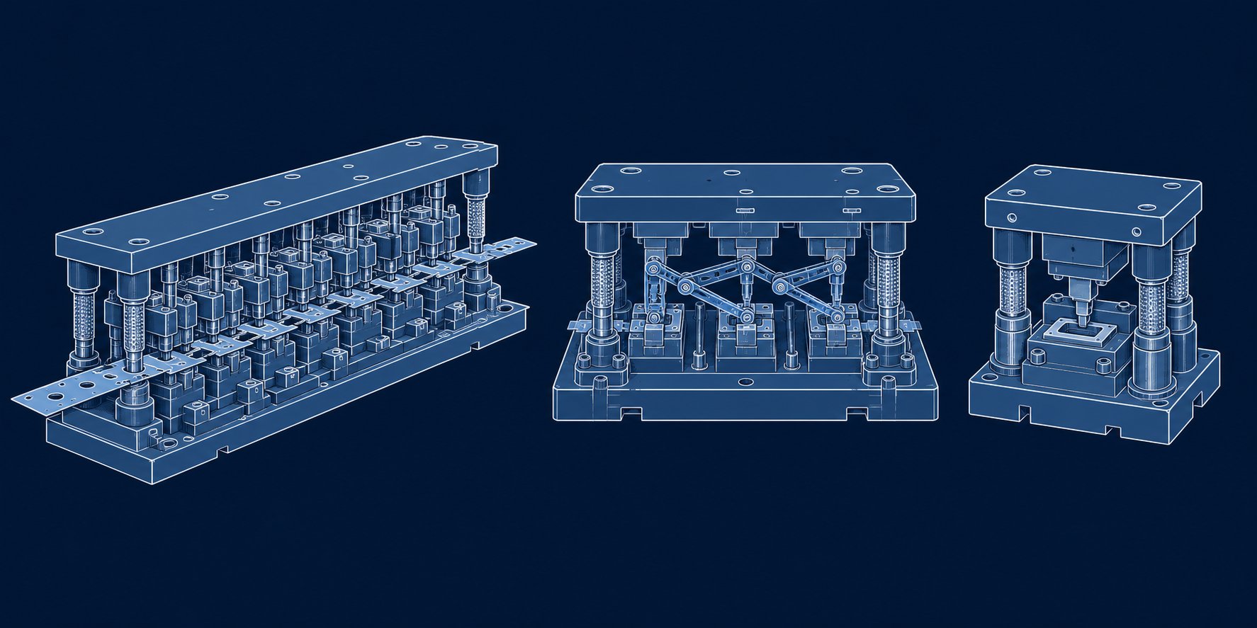
Every functional subsystem discussed so far exists in some form across all types of stamping dies. But the specific components, their arrangements, and their maintenance demands shift dramatically depending on whether you are working with a progressive, transfer, or compound architecture. A lifter that is critical in a progressive die does not even exist in a transfer die. A shedder that plays a minor role in a progressive tool becomes the primary ejection mechanism in a compound setup. Knowing these differences gives tooling engineers a practical edge when specifying replacements, planning maintenance intervals, or communicating with die builders about new projects.
Three die architectures dominate sheet metal manufacturing, each optimized for different production volumes, part geometries, and material utilization targets. The components inside them reflect those priorities.
Progressive Die Components
Progressive dies carry the workpiece through multiple stations on a continuous strip of material. The part stays connected to the carrier strip from start to finish, with a final cutoff operation separating the completed piece at the last station. This architecture produces the most complex dies and stamping component configurations because every station must align to the same datum, and the strip must index precisely through the entire tool without distortion or feed error.
What makes progressive die components unique?
- Carrier strips and connecting webs - The strip layout must include enough material between stations to carry the developing part through the die without tearing or buckling. These carriers are not "extra" material in the design sense. They are engineered structural elements whose width, shape, and stiffening ribs directly affect feed stability.
- Pilot pins at every station - Unlike simpler dies that might use one or two pilots, progressive dies typically require pilot pins at each working station. The strip must re-register at every index to maintain station-to-station alignment within thousandths of an inch. Worn pilot pins in a 12-station progressive die create compound errors that escalate with each successive operation.
- Inter-station lifters - The continuous strip must clear all lower die surfaces, formed features, and tooling between strokes. This demands a system of lifters, bypass notches, and rail guides spanning the full die length. A transfer die eliminates this complexity entirely because individual parts are picked up and placed rather than dragged across the tool.
- Sequential punch arrangements - Cutting and forming operations are distributed across stations in a carefully planned sequence. Each station handles one or two operations, and the punch geometry at each position reflects only that station's task. This distribution keeps individual punch loads manageable but multiplies the total number of cutting components that need inspection and maintenance.
Progressive dies have the most demanding stripping and guiding requirements of any die type. The strip must be held flat at every station during cutting, stripped cleanly from multiple punches simultaneously, and lifted uniformly across a tool that might span several feet. Spring systems must deliver consistent force across all stations, and any variation in lifter height disrupts pilot pin engagement downstream. This is why progressive dies require more frequent preventive maintenance than other architectures, particularly for springs, pilots, and guide bushings.
The automotive stamping die sector relies heavily on progressive tooling for high-speed production of brackets, connectors, terminals, and structural reinforcements where cycle rates exceed 600 strokes per minute. At those speeds, every component interaction amplifies, and wear that would go unnoticed in a slower die creates visible defects within hours.
Transfer Die Components
Transfer dies take a fundamentally different approach to part movement. Instead of carrying the workpiece on a continuous strip, they separate the blank from the coil at the first station and then move individual parts between stations using mechanical fingers, rails, or vacuum grippers synchronized with the press stroke. This changes the component landscape significantly.
As Peter Ulintz of MetalForming Magazine explains, transfer dies are designed much like dies for individual press-line operations, with important differences: all stations must maintain a common pass line and shut height, guide pins and heel blocks mount to the upper die shoe to avoid interfering with transfer rail movement, and lower die sections must provide clearance for transfer fingers to pick up and place parts.
Key components unique to transfer dies include:
- Part locating nests - Since no carrier strip holds the part in position, each station needs a precision nest or locator that receives the part from the transfer mechanism and holds it in exact orientation for the operation. These nests must account for part growth as forming progresses and provide consistent pickup points for the next transfer.
- Transfer fingers and grippers - Mechanical fingers clamp the part edges and carry it from station to station in a synchronized motion. Some systems use vacuum cups for flat parts or magnetic grippers for ferrous materials. The gripper design must accommodate part geometry changes as forming operations reshape the workpiece at each station.
- Timing mechanisms - Transfer motion must synchronize precisely with the press stroke. Transfer motion curves and interference curves, which depict the automation's travel path relative to die components, must be available to the die designer to prevent collisions between fingers and die surfaces.
Transfer dies eliminate lifters, bypass notches, and carrier strip engineering entirely. They also eliminate the material waste inherent in progressive die carrier webs. Larson Tool notes that transfer grippers take the place of the carrying web, saving material on each part and reducing overall piece price. This material utilization advantage becomes significant when stamping thick or expensive alloys.
The tradeoff is additional complexity in cam operations, part orientation control, and inter-station handling. Cam operations that must fit within tight pitch constraints in a progressive die can be designed for maximum accessibility and adjustment in a transfer setup. However, the transfer mechanism itself introduces wear components, sensors, and synchronization points that do not exist in progressive tooling. Maintenance extends beyond the die to include the transfer system, creating a broader scope of components that can cause downtime.
The automotive stamping die industry uses transfer tooling extensively for large body panels, structural components, and deep-drawn parts where blank size or forming depth makes progressive strip feeding impractical.
Compound Die Components
Compound dies occupy the opposite end of the complexity spectrum. They perform multiple cutting operations simultaneously in a single press stroke, typically combining blanking and piercing so the external profile and internal features are cut at the same time. This architecture produces the flattest, most concentric parts of any die type because all cutting forces are balanced in a single plane during one instant.
The defining feature of compound die components is their inverted arrangement. In a standard die, the punch mounts in the upper shoe and pushes material down through the die block in the lower shoe. In a compound die, this relationship is flipped for the blanking operation: the blanking punch sits in the lower shoe, and the blanking die (or die ring) mounts in the upper shoe. Piercing punches, meanwhile, still mount conventionally in the upper shoe, passing through the blanking die to pierce holes in the blank as it is being cut from the strip.
This inversion has direct consequences for ejection:
- Upper shedder - After blanking, the finished part tends to stay lodged in the upper die ring. A spring-loaded shedder plate mounted in the upper shoe pushes the part out on the upstroke, allowing it to fall free or be directed to an exit chute. Shedder force and travel must overcome any friction or spring-back holding the part inside the die opening.
- Lower knockout - The strip skeleton (scrap) tends to cling to the lower blanking punch after cutting. A spring-loaded stripper or knockout pin system in the lower shoe pushes the strip free so it can advance for the next stroke.
Compound dies do not require lifters, pilot pins at multiple stations, or bypass notches because all work happens in one stroke at one location. Their component count is substantially lower than progressive or transfer dies. Keats Manufacturing confirms that compound die stamping delivers high repeatability for single-die cases with one stroke producing flatter parts than sequential operations can achieve.
The simplicity comes with limitations. Compound dies handle flat or near-flat parts: washers, laminations, shims, and similar components where the geometry lives in a single plane. They cannot perform bending, drawing, or multi-axis forming. Part complexity must be low, but precision can be extremely high because all features are cut relative to each other in a single alignment event.
Maintenance is correspondingly straightforward. Fewer components mean fewer wear points. Inspection focuses on cutting edge condition, shedder spring health, and concentricity between the blanking die and piercing punches. When compound dies wear out of tolerance, concentricity between inner and outer features shifts, producing parts where hole positions drift relative to the blank edge.
Comparing Die Architectures by Component Characteristics
The table below maps the practical differences across these three types of dies, giving tooling engineers a quick reference for component planning, spare parts strategy, and maintenance scheduling:
| Characteristic | Progressive Die | Transfer Die | Compound Die |
|---|---|---|---|
| Component Count | High (dozens to hundreds across stations) | Moderate to high (die components plus transfer mechanism) | Low (single-station tooling) |
| Typical Production Volume | High volume, high speed (often 600+ SPM) | Medium to high volume, moderate speed | Small to medium volume, moderate speed |
| Part Complexity Capability | High (bends, forms, draws distributed across stations) | Very high (large parts, deep draws, rotation possible) | Low (flat parts, single-plane cutting only) |
| Maintenance Frequency | Frequent (many wear points, complex stripping and guiding) | Moderate die maintenance, plus transfer system upkeep | Low (fewer components, simpler inspection scope) |
| Unique Components | Carrier strips, inter-station lifters, bypass notches, multi-station pilots | Locating nests, transfer fingers/grippers, timing cams | Inverted blanking punch, upper shedder, compound stripper |
| Material Utilization | Moderate (carrier webs create waste) | High (no carrier web, nested blanking possible) | Moderate to high (depends on blank layout) |
Choosing between these architectures is not just a production volume decision. It is a component strategy decision. Progressive dies demand a deeper spare parts inventory and more frequent spring, pilot, and bushing replacements. Transfer dies shift maintenance attention toward the automation system and part handling components. Compound dies minimize component count but require precise concentricity checks that demand skilled measurement.
Regardless of architecture, certain components wear faster than others across all types of dies. Cutting edges degrade first, guide bushings follow, and spring systems fatigue quietly in the background. Understanding which parts fail first, and how sourcing decisions affect your ability to respond, determines whether a die runs profitably or bleeds money through unplanned downtime.
Component Wear Patterns and Sourcing Decisions
Knowing which stamping die parts exist and how they function is one thing. Knowing which ones fail first, how to detect degradation before it becomes a crisis, and where to source replacements quickly is what separates a reactive toolroom from a profitable one. Die design determines capability, but wear management determines whether that capability holds across a production run of ten thousand parts or ten million.
Every metal stamping dies application follows a predictable wear hierarchy. The components in direct, repeated contact with the workpiece under shear stress always degrade first. Those with sliding friction wear next. Those absorbing cyclic impact follow behind. Recognizing this pattern lets you schedule inspections where they matter most and allocate spare parts budgets toward the components that actually drive downtime.
Wear Hierarchy and Inspection Priorities
Not all stamping die parts wear at the same rate. The hierarchy is driven by physics: the closer a component gets to the workpiece and the higher the stress it absorbs, the faster it degrades. Here is the practical order, from fastest-wearing to slowest:
Cutting edges degrade first. Punches and die blocks experience direct shear stress against the workpiece on every single stroke. That contact generates friction, heat, and micro-abrasion that rounds cutting edges progressively. In steel stamping dies running high-strength materials, edge wear accelerates further because the work material resists fracture and transfers more load into the tooling. Preventive maintenance data confirms that burr formation is typically the first visible quality indicator of edge degradation, appearing well before the edge shows obvious damage to the naked eye.
Guide bushings wear second. Every press stroke slides the guide pin through its bushing under load. That continuous friction, repeated millions of times, opens running clearance gradually. Bronze bushings score and lose diameter. Ball-bearing cages develop flat spots. The wear is invisible from outside the die, but it shows up as part-to-part dimensional variation that drifts wider over time.
Strippers and pressure systems fatigue third. Springs compress and release on every cycle. Die springs lose free length. Nitrogen cylinders lose gas pressure. Urethane pads creep and soften. Stripper plates themselves accumulate witness marks and surface damage from repeated impact against the material. This degradation is gradual and often masked because remaining springs compensate for failed ones until the system reaches a tipping point.
Structural components wear last. Die shoes, backup plates, and mounting hardware operate under compressive loads without sliding friction or direct workpiece contact. They can last the entire life of a die if properly sized. When they do fail, it typically traces back to localized overload from a missing backup plate or inadequate shoe thickness rather than normal operational wear.
This hierarchy gives you a practical inspection framework. Instead of checking everything equally on every maintenance stop, concentrate effort where wear accumulates fastest. The table below connects the wear hierarchy to observable part quality indicators that signal degradation before catastrophic failure occurs:
| Wear Priority | Component Group | Quality Indicator | What It Signals |
|---|---|---|---|
| 1st (fastest) | Punch edges, die blocks, cutting inserts | Increasing burr height on stamped parts | Edge rounding or chipping has reduced shear effectiveness |
| 2nd | Guide bushings, ball-bearing cages | Dimensional drift between consecutive parts | Running clearance has opened, allowing lateral die-half movement |
| 3rd | Die springs, nitrogen cylinders, stripper plates | Inconsistent part flatness, slug pulling events | Stripping force has dropped below threshold for clean material control |
| 4th (slowest) | Die shoes, backup plates, fasteners | Visible peening, loose mounting, audible shifting | Localized overload has exceeded structural capacity |
You will notice that each indicator connects to a specific subsystem. Increasing burr height does not require a full die teardown. It points directly to the cutting system. Dimensional drift isolates the guiding system. Flatness issues implicate stripping. This targeted approach reduces diagnostic time and keeps maintenance focused on what actually needs attention during each service stop.
Standard Catalog vs. Custom-Machined Components
When a worn component needs replacement, the sourcing path depends entirely on whether the part is a standard catalog item or a custom-machined piece. This distinction fundamentally affects spare parts strategy, lead time exposure, and die maintenance planning for every sheet metal die in your shop.
Standard catalog components are off-the-shelf items manufactured to industry specifications and stocked by multiple suppliers. They ship quickly, often next-day, and cost relatively little because they are mass-produced. The category includes:
- Guide pins and bushings in standard diameters and lengths
- Die springs in standard bore sizes, color-coded by deflection rate
- Round punches in common diameters with standard head styles
- Pilot pins in standard tapers and lengths
- Dowel pins, socket head cap screws, and keeper retainers
- Ball-bearing guide assemblies in standard die set sizes
For these items, the smart strategy is stocking. Keep critical sizes on hand so a worn bushing or broken spring never holds up production while waiting for delivery. Catalog suppliers like Misumi, Dayton, and Danly maintain extensive inventories specifically because these wear items need fast turnaround.
Custom-machined components are unique to your specific die design. They cannot be pulled from a catalog because their geometry, tolerances, or material specifications are specific to the application. This category includes:
- Die blocks with custom cutting profiles, especially wire-EDM profiled openings
- Shaped punches with non-standard cross-sections
- Forming inserts matched to specific part geometry
- Sectional cutting inserts sized to fit proprietary die block pockets
- Custom lifter assemblies and bypass notch details
- Shedder plates matched to specific cavity depths
Custom components require lead time. Someone must program a wire-EDM machine, heat-treat the blank, grind it to final tolerance, and verify dimensions. That process takes days to weeks depending on complexity. For critical steel stamping dies running high-volume production, this lead time translates directly into lost revenue if a custom part fails without a spare on hand.
The practical solution is a tiered spare parts strategy. Stock all standard components that appear in your die's bill of materials. For custom components, maintain at least one spare of the items with the highest wear rates, typically shaped punches and sectional die inserts. For lower-wear custom items like die blocks and forming tools, keep detailed drawings and material specifications on file so replacement orders can be placed immediately when wear reaches threshold, rather than scrambling to reverse-engineer dimensions from a worn-out original.
Stamping die design documentation becomes your insurance policy here. A complete die build package with full component drawings, material call-outs, heat-treat specifications, and assembly notes transforms a multi-week emergency into a routine reorder. Without that documentation, every custom replacement becomes a reverse-engineering project that adds cost and uncertainty.
Selecting a Die Component Partner
Standard catalog items are commodity purchases. Price and delivery speed dominate the decision. Custom-machined components are a different story. The supplier you choose for die blocks, shaped punches, forming inserts, and other design-specific parts directly influences how quickly you recover from wear events and how well replacement components perform once installed.
Not all custom component suppliers are equal. A shop that can wire-cut a profile is not necessarily equipped to advise on clearance optimization, recommend the right tool steel grade for your work material, or hold the tolerances that high-speed progressive dies demand. Evaluating a die component partner requires looking beyond machining capacity to engineering depth.
Key criteria to assess when sourcing custom stamping die parts:
- Engineering support for complex geometries - Can the supplier review your part requirements and suggest improvements to die design that extend component life? Do they understand how clearance, punch geometry, and material selection interact? A supplier that simply cuts what you draw misses the opportunity to solve root-cause wear problems.
- Material expertise across tool steels and carbides - Different applications demand different materials. A partner should recommend whether A2, D2, M2, powdered metal, or carbide is the right choice based on your production volume, work material, and press speed rather than defaulting to one grade for everything.
- Tolerance capabilities verified by metrology - Wire-EDM tolerances of +/-0.0001 inches matter for die openings, but only if the supplier verifies them with CMM inspection rather than assuming machine accuracy equals part accuracy. Ask how they validate finished dimensions.
- Turnaround time aligned with production urgency - A supplier quoting six weeks for a replacement die insert while your press sits idle is not a viable partner for production tooling. Look for suppliers who maintain capacity for urgent orders and communicate realistic timelines upfront.
- Understanding of the full die system - The best component suppliers understand how their parts interact with the rest of the die. They consider backup plate hardness, stripping forces, and alignment requirements when specifying a replacement punch rather than treating it as an isolated piece of steel.
For tooling engineers sourcing custom components that involve die structure, punch geometry, clearance optimization, or burr control challenges, YICHEN offers engineering support connecting stamping die design intent to production-ready solutions. Their approach addresses the full system context rather than treating replacement components as isolated machining jobs, which matters most for design-heavy applications where component interactions drive quality outcomes.
Questions worth asking any prospective die component partner before committing:
- Can you provide DFM feedback on component designs that are experiencing premature wear?
- What tool steel grades and carbide options do you stock or source regularly?
- What is your standard lead time for wire-EDM profiled die inserts, and can you expedite for production-down situations?
- Do you offer heat treatment in-house or through a certified partner with documented processes?
- How do you verify final tolerances, and will you provide inspection reports with delivery?
- Can you manufacture replacement components from existing worn samples when drawings are unavailable?
- Do you support ongoing production needs with scheduled replacement programs, or only one-off orders?
The answers to these questions reveal whether a supplier is a transactional vendor or a genuine partner in your tooling strategy. Given that custom components sit on the critical path between die failure and production recovery, this distinction directly affects your uptime, scrap rate, and total cost of ownership across every die in the shop.
Frequently Asked Questions About Stamping Die Parts
1. What are the main parts of a stamping die?
A stamping die consists of five functional subsystems: the structural system (die shoes, backup plates, fasteners), cutting system (punches, die blocks, inserts), guiding system (guide pins, bushings, pilot pins), stripping system (stripper plates, springs, pressure pads), and ejection system (knockout pins, shedders, lifters). Each subsystem activates during specific phases of the press stroke, and all must work together to produce quality parts. Understanding these groups helps tooling engineers diagnose defects by tracing problems back to the responsible subsystem rather than inspecting every component equally.
2. What is the purpose of clearance between a punch and die block?
Clearance is the gap between the punch cutting edge and the die block edge, measured per side and expressed as a percentage of material thickness. Its purpose is to align fracture planes from both edges so they meet cleanly within the material, producing a smooth shear zone with minimal burr. Standard clearance for mild steel is typically 8-12% per side. Insufficient clearance increases punch load and causes premature edge chipping, while excessive clearance produces rolled edges, heavy burrs, and dimensional variation requiring secondary deburring. Clearance must be recalculated whenever work material changes because harder materials require larger gaps.
3. Which stamping die components wear out first?
Cutting edges on punches and die blocks wear fastest because they experience direct shear stress against the workpiece on every stroke. Guide bushings wear second due to continuous sliding friction under load. Stripping springs and pressure systems fatigue third as they compress and release millions of times, gradually losing preload. Structural components like die shoes wear last since they only absorb compressive loads without direct workpiece contact. Monitoring burr height, dimensional drift, and part flatness provides early warning of degradation in each respective subsystem before catastrophic failure occurs.
4. What is the difference between progressive, transfer, and compound dies?
Progressive dies carry workpieces through multiple stations on a continuous strip, requiring pilot pins, lifters, and bypass notches at each station. They excel at high-speed production of complex parts. Transfer dies separate the blank at the first station and move individual parts between stations using mechanical fingers or grippers, eliminating carrier strip waste but adding automation complexity. Compound dies perform blanking and piercing simultaneously in one stroke, producing the flattest and most concentric parts but limited to single-plane geometries. Each architecture demands different component configurations, maintenance frequencies, and spare parts strategies.
5. How do you choose between standard catalog and custom-machined die components?
Standard catalog components like guide pins, bushings, die springs, and round punches are mass-produced to industry specifications and ship quickly at low cost. Stock these items on hand for fast replacement. Custom-machined components like die blocks with wire-EDM profiles, shaped punches, and forming inserts are unique to your die design and require days to weeks of lead time. For these, maintain spares of highest-wear items and keep detailed drawings with material and heat-treat specs on file. Partners like YICHEN (https://www.yichen-group.com/stamping-die/) provide engineering support for custom components where clearance optimization, material selection, and system-level understanding matter beyond basic machining capability.


