


What Are Bypass Notches and Why They Matter in Stamping Dies
When you run a progressive stamping die at production speed, smooth strip feeding is everything. A single misfeed can cascade into die damage, scrap parts, and costly downtime. Bypass notches are one of the most effective yet often overlooked solutions built into stamping dies to keep that strip moving cleanly from station to station.
What Are Bypass Notches in Progressive Stamping Dies
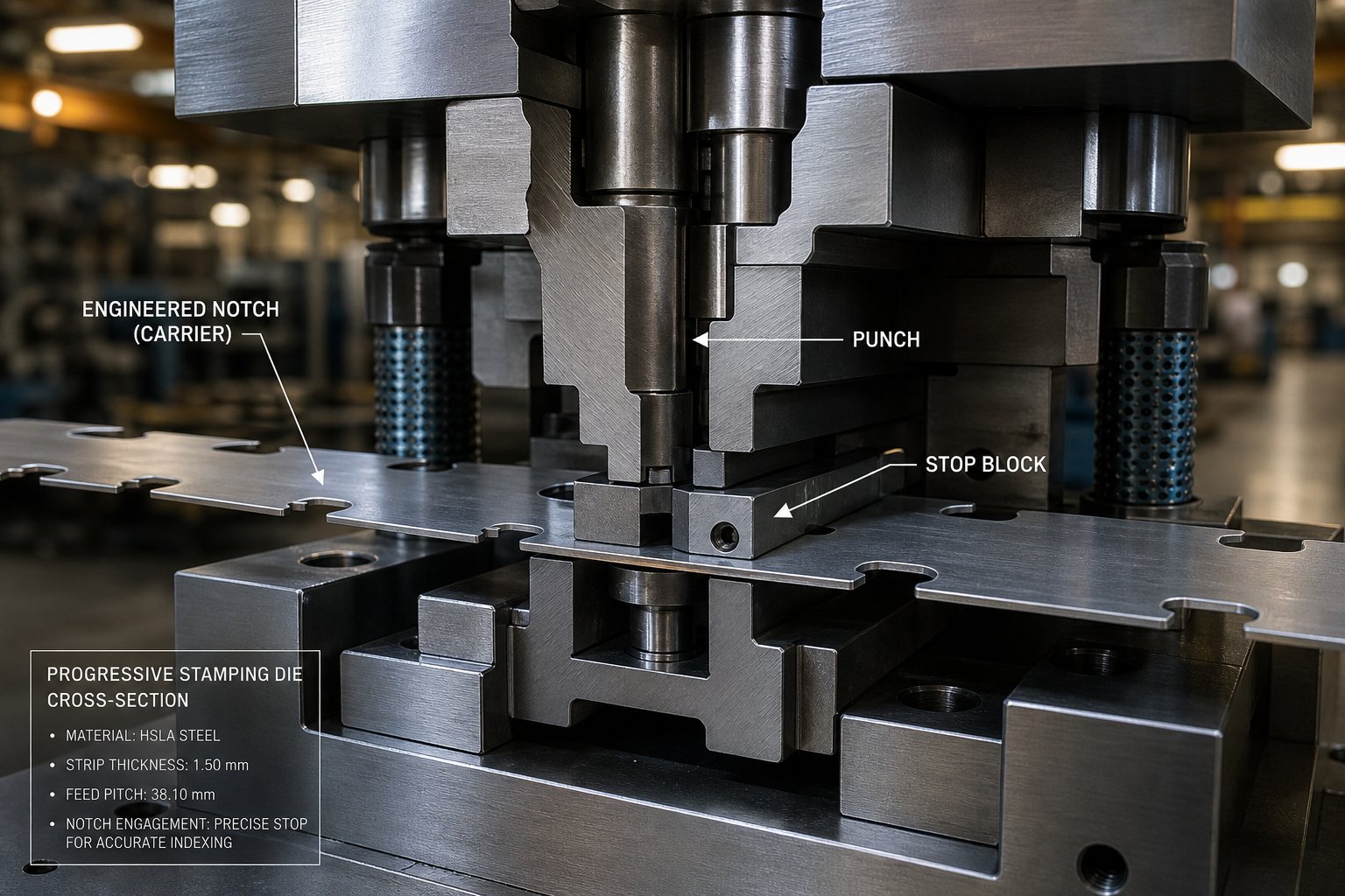
Bypass notches are engineered relief cuts made in the carrier strip of progressive stamping dies. Their purpose is to prevent overfeeding, control strip registration, and provide clearance so formed features can pass through subsequent die stations without interference.
If you are new to the field and wondering what is metal stamping, it is a manufacturing process that uses dies mounted in presses to shape flat sheet metal into finished parts. Progressive stamping dies take this a step further by performing multiple operations in sequence as the strip advances through the tool. The carrier strip ties the part blanks together and moves them forward one pitch at a time.
Bypass notches are cut from one or both edges of this carrier strip, typically at the first stations of the die. They create a straight-edged reference that interacts with solid stops inside the tool, giving the strip a precise mechanical limit for each feed progression. Industry professionals sometimes call them pitch notches or French notches, though there are contextual differences worth understanding.
The Strip Feeding Problem Bypass Notches Solve
Imagine feeding a continuous coil strip through a progressive die without any mechanical stop. What happens? The coil feeder advances the material, but even feeders accurate to 0.0005 inch cannot account for edge camber introduced during the slitting process. That camber makes the strip wander, buckle, or overfeed. The result is misregistration between stations, half-hits on punches, and in the worst case, a full die crash.
The purpose of bypass notches in stamping dies is to solve exactly this. By removing a small section of material from the strip edge, the notch creates a solid stop surface and eliminates severe edge camber in a single operation. This bypass notches sheet metal forming purpose extends beyond simple overfeeding protection. The straight-line cut also helps the strip feed smoothly through guide rails, and when paired with pilot pins, provides reliable part-to-part registration across every station.
Understanding what is stamping at this level means recognizing that feeding accuracy is not just a feeder problem. It is a die design problem. And bypass notches represent a deliberate, engineered answer to strip control challenges that no amount of electronic die protection can fully replace on its own.
The terminology around these notch features varies across shops and regions, which often creates confusion for engineers reviewing die designs from different suppliers.
Bypass Notches vs Pitch Notches and Industry Terminology
Ask five die designers what they call the relief cuts in a progressive die carrier strip, and you might get five different answers. "Bypass notch," "pitch notch," "French notch," "feed notch" - the terminology shifts depending on who trained you, where you work, and which region of the country (or world) your shop operates in. This inconsistency is not just trivia. It creates real confusion when sourcing dies from different suppliers or reviewing strip layouts from unfamiliar shops.
Bypass Notches vs Pitch Notches Terminology Explained
At the broadest level, both terms describe similar geometry - a section of material removed from or formed into the strip edge to control feeding. The functional overlap is significant, and many professionals in dies and stamping use the terms interchangeably without issue. Still, there are contextual distinctions worth noting.
The term "pitch notch" tends to be reserved for notch geometry specifically tied to pitch advancement and first-hit control. Its primary role, per the stamping definition used by most tooling engineers, is to provide a solid stop that prevents overfeeding and gives setup personnel a precise starting location for the leading strip edge. Art Hedrick of Dieology LLC describes the pitch notch as a small section of material cut from one or both strip edges at the beginning stations of a progressive die, functioning as both a mechanical stop and a camber-correction feature.
"Bypass notch," on the other hand, often carries a broader meaning. Some professionals use it to describe any relief geometry that allows strip material - particularly formed features - to pass through or bypass subsequent stations without interference. In this context, what are dies doing differently? The distinction is subtle: a pitch notch controls where the strip stops, while a bypass notch controls what the strip clears as it moves forward.
In practice, many die stamps incorporate geometry that serves both functions simultaneously. The same notch that provides a solid pitch stop may also create clearance for a downstream bend or draw. That dual function is partly why the terms merged in everyday shop language.
How Regional and Company Conventions Shape Naming
Geography and company culture play a larger role in terminology than most engineers realize. Shops in the upper Midwest of the United States, where progressive die stamping has deep roots, tend to favor "pitch notch" or "French notch." European and Asian die builders more frequently use "bypass notch" or equivalent translations. Larger OEMs with global supply chains sometimes standardize on one term in their die design specifications, but that standard varies by company.
Understanding what is dies in manufacturing means accepting that nomenclature is not universal. When reviewing a die design package from an unfamiliar supplier, the safest approach is to look at the geometry and its position in the strip layout rather than relying on the label alone.
The table below summarizes how these terms typically map to specific usage contexts:
| Term | Typical Usage Context | Functional Description |
|---|---|---|
| Pitch Notch | North American progressive die shops; die setup and feed control discussions | Material removed from strip edge to create a solid stop for pitch advancement, prevent overfeeding, and remove edge camber |
| French Notch | Legacy term common in older tooling literature and experienced die makers | Synonymous with pitch notch; refers to the same slug-producing relief cut at strip edges |
| Bypass Notch | Broader global usage; forming-heavy progressive dies; strip clearance discussions | Relief geometry allowing formed features to clear subsequent stations; may also serve as a pitch stop |
| Lance-and-Flange Notch | Applications requiring slug-free operation or carrier stiffening | Lanced and bent material that acts as a solid stop without producing a separate slug |
Regardless of what your shop calls them, the underlying mechanical function remains consistent. These features exist to keep the strip feeding reliably and to protect expensive die components from crash damage. The real differences emerge when you look at how they physically interact with strip progression, pilot pins, and formed geometry at each station.
How Bypass Notches Function in Progressive Die Strip Feeding
Knowing what bypass notches are called is one thing. Understanding what they actually do inside a stamping die during each press stroke is where the real engineering value lives. The mechanical function of these relief cuts goes far beyond simple overfeeding prevention. They actively participate in strip control, forming clearance, and registration accuracy throughout the entire die process.
How Bypass Notches Control Strip Movement
Picture a progressive stamping die running at 200 strokes per minute. The strip advances one pitch length between each hit, and the entire stamping process depends on that movement happening with repeatable precision. Bypass notches serve as the mechanical backbone of that precision.
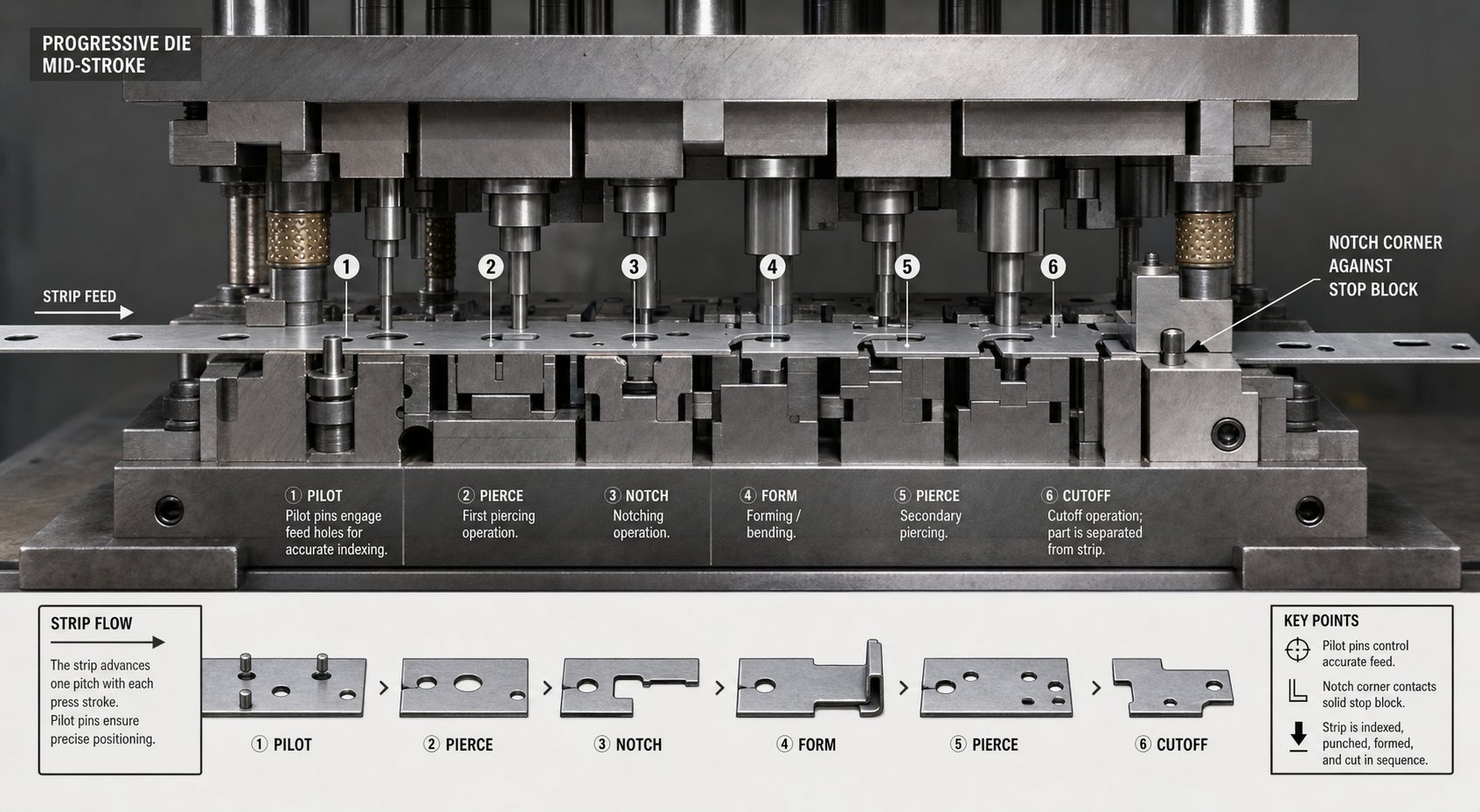
When the feeder releases the strip, it moves forward until the notch corner contacts a solid stop block mounted in the die. This hard stop eliminates any cumulative feeding error that might build up over hundreds of progressions. Unlike electronic sensors that detect misfeeds after they happen, the physical stop created by the notch geometry prevents the problem from occurring in the first place.
The notch also removes edge material that could otherwise interfere with smooth feeding through guide rails. Coil stock often arrives with slight edge burrs or camber from the slitting process. By cutting a clean, straight-edged reference into the strip, the bypass notch gives the die a reliable surface to index against regardless of incoming material condition.
For dies that perform punching stamping operations at early stations, the bypass notch punch typically fires simultaneously with pilot hole piercing. This means the strip gains both its registration holes and its edge control geometry in a single hit, establishing all location references before the material reaches any forming stations downstream.
Interaction Between Bypass Notches and Pilot Pin Registration
Bypass notches and pilot pins work as a team, but they handle different aspects of strip control. Pilot pins provide precise X-Y location by engaging pre-pierced holes and pulling the strip into exact position as the die closes. Bypass notches, meanwhile, set the coarse feed limit and provide Z-axis clearance for formed features.
Here is how the sequence plays out during a single press stroke cycle:
- The feeder advances the strip forward by one pitch length. The strip moves freely through the open die until the bypass notch corner contacts the solid stop, preventing overfeeding.
- The press ram begins its downstroke. As the upper die descends, pilot pins enter the pre-pierced holes in the strip, pulling the material into precise final position and correcting any minor lateral misalignment.
- The stripper plate contacts the strip surface, clamping it flat against the lower die face. At forming stations, lifters may hold the strip at an elevated position to clear previously formed features below.
- Punching stamping and forming operations execute simultaneously across all stations. At the first station, new bypass notches and pilot holes are cut into the incoming strip. At downstream stations, bends, draws, and embosses take shape.
- The ram reverses direction. Strippers hold the strip while punches withdraw. Lifters raise the strip back to feed height, and the bypass notch geometry provides the clearance needed for formed features to clear lower die components as the strip lifts.
- The feeder engages again, advancing the strip to the next pitch position, and the cycle repeats.
Without bypass notches providing that initial coarse stop, the pilot pins alone would bear the full burden of correcting any feed error. Pilots are precision stamping die components designed for fine location, not for absorbing the force of an overfed strip. Relying on them as primary stops accelerates pin wear and eventually leads to misregistration across all stations.
Preventing Strip Lifting and Misfeed During Progression
Strip lifting is one of the most persistent headaches in progressive die operation. When a forming station bends material downward, the surrounding carrier strip wants to deflect upward in response. If that lifted material catches on a die component as the strip feeds forward, you get a misfeed or a buckling event that can crash the tool.
Bypass notches address this in two ways. First, by removing material from the carrier edge adjacent to forming stations, they reduce the stiffness of the carrier in that zone. A less rigid carrier is more compliant, meaning it can flex slightly without transmitting lifting forces across the full strip width. This is consistent with carrier strip design principles that balance flexibility with structural integrity.
Second, the notch geometry itself creates physical clearance. When a formed feature like a bent tab or drawn cup needs to pass through the next station, the bypass notch ensures there is open space at the strip edge for that feature to travel without contacting die steel. This is especially critical in stamping die designs where stations are closely spaced and formed features extend below or above the strip plane.
The relationship between notch placement and strip stability is a balancing act. Cut too much material from the carrier and you lose the structural strength needed to push the strip through the die reliably. Cut too little and formed features collide with downstream tooling. Getting this balance right requires understanding the specific notch geometry options available and when each configuration fits the application best.
Types of Bypass Notches and When to Use Each Configuration
That balancing act between clearance and carrier strength does not have a one-size-fits-all solution. Different part geometries, material gauges, and forming depths call for different notch shapes. Among the various types of stamping dies in production, progressive tools see the widest variety of bypass notch configurations because each station introduces unique clearance demands. Choosing the right geometry is not a cosmetic decision. It directly affects strip stability, scrap behavior, and punch life.
V-Notch Configuration and Typical Applications
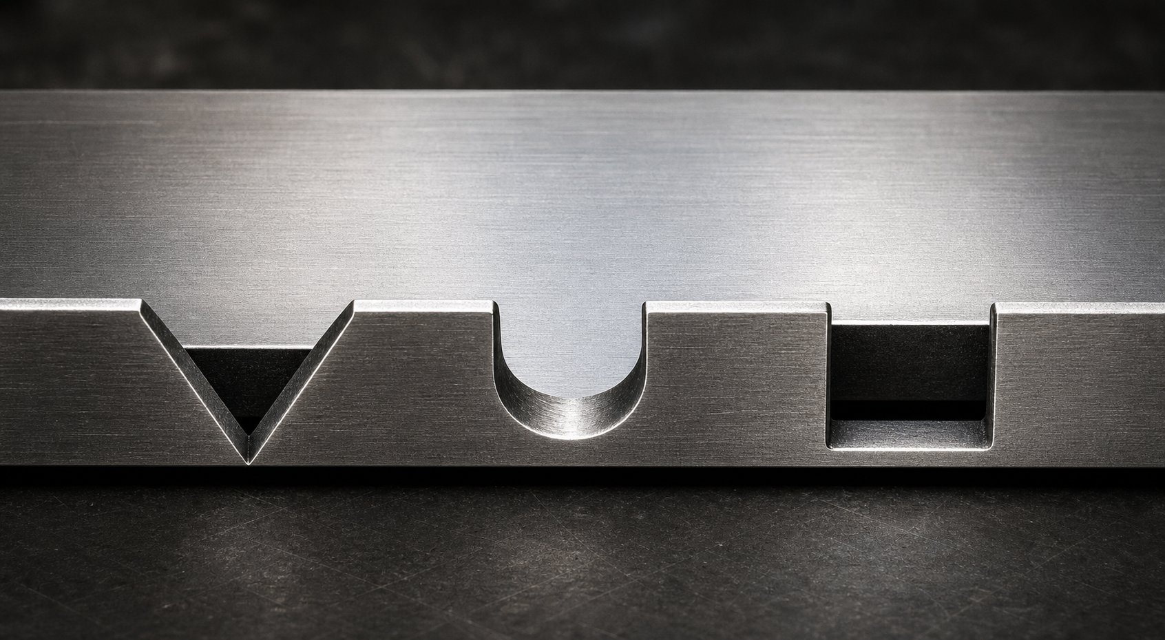
The V-notch is the most common bypass notch geometry in die stamping operations. It features two angled cuts that meet at a point, creating a triangular relief in the strip edge. The angle of the V typically ranges from 60 to 90 degrees, though some applications use narrower or wider profiles depending on clearance needs.
Why is the V-notch so popular? Its tapered shape naturally guides the strip toward the solid stop as the material feeds forward. The angled edges act as a lead-in, centering the strip laterally and reducing the chance of a notch corner hanging up on the stop block. This self-centering behavior makes V-notches particularly effective in high-speed progressive dies where the strip must index quickly and cleanly.
V-notches work best in applications with moderate clearance requirements and thinner strip stock, typically below 2.0 mm. They produce a compact slug that ejects reliably, and the pointed geometry concentrates less stress at the carrier edge compared to sharp rectangular corners. However, V-notches offer limited clearance width at the strip edge, which can be a constraint when formed features need a wider window to pass through.
U-Notch and Rectangular Bypass Notch Designs
When a V-notch cannot provide enough clearance width, U-notch and rectangular configurations step in. These geometries remove a wider section of material from the carrier edge, creating a broader relief window for formed features to pass downstream stations.
The U-notch has a semicircular or radiused bottom, which distributes stress more evenly than a sharp-cornered pocket. This makes it a strong choice for bypass notches in sheet metal forming applications where the carrier strip experiences repeated bending loads during lifter operation. The radius at the notch root reduces the chance of fatigue cracking, especially in materials prone to work hardening.
Rectangular notches, by contrast, maximize the clearance area for a given notch depth. They are straightforward to machine into the die and produce a simple slug shape. The trade-off is that sharp inside corners create stress concentration points. In harder or thinner materials, those corners can initiate cracks after thousands of press cycles. Adding small corner radii (even 0.5 to 1.0 mm) mitigates this risk substantially without sacrificing meaningful clearance.
Both U-notch and rectangular designs are common in progressive dies with deep forming stations, large embossments, or multiple bends that extend well below the strip plane. If the formed feature needs significant room to travel, these wider geometries deliver it.
Positive vs Negative Bypass Notch Geometry
Beyond the shape of the cut itself, bypass notch design splits into two fundamental categories based on how material is handled: positive and negative. Understanding negative and positive bypass notches in sheet metal stamping dies is essential because the choice affects carrier strength, slug management, and overall strip behavior differently.
A negative bypass notch is what most engineers picture first. Material is physically removed from the strip edge, creating a cutaway that provides clearance. The removed slug must be managed through proper die venting and scrap chutes. Negative notches are the standard approach in most die stamping applications because they offer predictable, consistent clearance geometry from the first hit onward.
A positive bypass notch takes a different approach. Rather than removing material, it retains or redirects strip material to create relief. Think of a lance-and-form operation where a tab is bent out of the carrier plane instead of being cut away entirely. The material stays attached to the strip but moves out of the interference zone. This method maintains more carrier cross-section, which improves strip rigidity and feeding stability. It also eliminates the slug entirely, solving scrap management issues in tight die layouts.
The practical meaning of these terms can vary between companies and die designers, so definitions should always be confirmed against the specific die drawing and strip layout standard in use. The table below captures the core distinctions:
| Geometry Type | Typical Use Case | Advantages | Limitations |
|---|---|---|---|
| V-Notch (Negative) | High-speed progressive dies with moderate clearance needs; thin strip stock under 2.0 mm | Self-centering feed action; compact slug; lower stress concentration at carrier edge | Limited clearance width; not ideal for deep-formed features requiring wide relief windows |
| U-Notch (Negative) | Applications with repeated bending loads; materials prone to work hardening or fatigue cracking | Radiused root distributes stress evenly; good fatigue resistance; moderate clearance width | Slightly more complex punch geometry; slug shape may require specific chute design |
| Rectangular (Negative) | Deep forming stations; large embossments or bends extending well below strip plane | Maximum clearance area for given depth; simple to machine; predictable slug geometry | Sharp corners create stress risers; requires added radii in harder or thinner materials |
| Positive (Lance-and-Form) | Tight die layouts where slug management is problematic; applications requiring maximum carrier rigidity | No slug produced; maintains carrier cross-section; improves feeding stability | Limited clearance depth; lanced tab may interfere if not fully controlled; adds forming complexity |
Selecting the right configuration for negative and positive bypass notches in sheet metal forming stamping dies comes down to four variables: strip thickness, material properties, the clearance your formed features require, and the forming depth at adjacent stations. A shallow coin or emboss might need only a narrow V-notch for clearance. A deep-drawn cup progressing through multiple stations likely demands a full-width rectangular or U-notch relief to pass without contact.
The geometry you choose also influences how the notch wears over time and how the die behaves at production speed. Sharper notch profiles cut cleanly but concentrate wear on smaller punch areas. Wider profiles spread the load but remove more carrier material. These trade-offs connect directly to the design parameters and placement rules that govern where each notch sits relative to pilots, part geometry, and station spacing.
Bypass Notch Design Parameters and Placement Guidelines
Every notch configuration discussed above lives or dies based on the numbers behind it. Shape alone does not guarantee performance. A V-notch cut too shallow still allows formed features to collide with downstream tooling. A rectangular notch cut too deep fractures the carrier strip under feeding load. Effective stamping die design requires precise control over four critical geometry parameters and disciplined placement relative to the rest of the strip layout.
Critical Geometry Parameters for Bypass Notch Design
When you sit down to dimension a bypass notch in a metal stamping die, these are the variables that determine whether your strip feeds cleanly at production speed or gives you headaches from day one:
- Notch Depth - The distance the notch extends inward from the strip edge. This must exceed the maximum height (or depth) of any formed feature that needs to pass through subsequent stations. A common starting guideline is to set notch depth at 1.5 to 2.0 times the formed feature height, providing a working clearance margin that accounts for material springback and slight strip misalignment during feeding.
- Notch Width - The dimension measured along the strip edge in the direction of feed. Notch width must accommodate the full length of the formed feature as it travels past the stop block, plus enough margin to prevent contact under worst-case feeding conditions. Width typically relates to station pitch - a notch narrower than 40 to 60 percent of the pitch distance may not provide adequate clearance for features that span the transition zone between stations.
- Notch Angle (V-notch specific) - The included angle between the two cut faces of a V-notch. Angles between 60 and 90 degrees offer the best balance of self-centering action and clearance volume. Sharper angles below 60 degrees produce more fragile notch tips prone to breaking under strip tension, while angles exceeding 90 degrees reduce the centering benefit and waste carrier material laterally.
- Spacing and Repetition - Bypass notches repeat at every pitch along the strip. Their spacing equals the die pitch exactly, ensuring each progression creates an identical stop reference. In some metal stamping die design layouts, notches appear on both strip edges (dual-sided) for improved lateral registration, especially in wide coil applications where single-sided notches allow the strip to pivot slightly during feeding.
These parameters interact with each other. Increasing notch depth without widening the notch opening creates a narrow slot that traps slugs and resists ejection. Widening the notch without adjusting depth may provide lateral clearance without solving vertical interference problems. Effective stamping design treats them as a system, not as independent dimensions.
Placement Guidelines Relative to Pilot Holes and Station Spacing
Where you position the notch punch in the strip layout matters as much as the notch shape itself. Placement follows a few core principles in sheet metal stamping dies:
Bypass notches should be cut at the earliest possible station, ideally station one or two. This ensures the strip gains its edge control reference before encountering any forming operations downstream. Cutting the notch early also means the straight edge is available for the maximum number of subsequent stations to index against.
The notch punch should fire at the same station as the pilot hole pierce whenever possible. This establishes both the coarse feed stop and the fine-location reference in a single hit, eliminating any positional error that could accumulate if these features were cut at different stations. In practice, most progressive die builders place the notch punch adjacent to the pilot punch in the same die block.
Laterally, notches should be positioned far enough from the part geometry that the carrier retains structural continuity between the notch and the nearest part blank edge. A general rule in metal stamping design is to maintain a minimum bridge width between the notch and adjacent cutouts equal to at least 1.5 times the strip thickness. Fall below that, and the carrier becomes a weak link prone to tearing under feed tension.
Balancing Clearance Depth with Carrier Strip Integrity
Here is the tension every die designer faces: deeper notches provide more clearance for formed features, but they also remove more material from the carrier edge. Remove too much and the carrier loses the cross-sectional strength needed to push the strip through guide rails and over lifters reliably.
Imagine a 1.0 mm thick steel strip with a 12 mm wide carrier on each side. If your bypass notch extends 8 mm inward, only 4 mm of carrier material remains intact at that cross-section. That remaining bridge must handle all feeding forces, lifter loads, and the dynamic stresses of high-speed press operation. In thinner or softer materials, that residual section may not be enough.
The engineering principle governing this balance is straightforward: notch depth should never consume more than 60 to 70 percent of the carrier width. Staying within this range preserves enough structural material to maintain feed reliability while still providing meaningful clearance for formed features. If your formed geometry requires deeper relief than this ratio allows, the correct response is to widen the carrier strip in the initial strip layout rather than pushing the notch deeper into an undersized carrier.
This is where stamping die design and strip layout optimization intersect. A metal stamping die that looks efficient on material usage but leaves insufficient carrier width for proper bypass notch depth ultimately costs more through misfeeds, die crashes, and scrap. The strip layout must be designed with notch geometry in mind from the start, not retrofitted after the die is built.
Material properties add another layer to this calculation. High-strength steels tolerate deeper notch ratios because their higher yield strength maintains carrier rigidity with less cross-section. Soft aluminum or copper alloys need more conservative depth limits because the remaining carrier deforms more easily under load. These material-specific adjustments deserve their own detailed treatment to avoid oversimplifying the design process.
Bypass Notches vs Alternative Strip Control Methods
Bypass notches are not the only way to control strip movement in a progressive die. Pilot pins, side cutters, plain carrier strips, and lifter-based systems all play roles in metal stamping tooling. So why choose one over another? The answer depends on registration demands, scrap targets, and how much complexity your stamping tooling budget can support. Each method has a sweet spot, and understanding the trade-offs helps you pick the right combination for a given application.
Bypass Notches Compared to Pilot Pins Alone
Pilot pins are the precision workhorses of strip registration. They enter pre-pierced holes and pull the strip into exact X-Y position every stroke. As Peter Ulintz of PMA notes, pilots must be sized with only 0.0005 to 0.001-inch clearance to their holes and must engage before any other punches contact the material. They deliver outstanding positional accuracy, often within a few thousandths of an inch.
But relying on pilot pins alone for feed control has a significant downside. Pilots are designed for fine location, not for absorbing the force of an overfed strip. If the feeder overshoots by even a fraction of a millimeter, the pilot pin takes that impact load side-on. Over thousands of cycles on a die stamping press running at production speed, that repeated side loading bends pilots, elongates pilot holes, and degrades registration across every station.
Bypass notches eliminate this problem by providing a coarse mechanical stop upstream of pilot engagement. The notch corner contacts the stop block first, absorbing the overfeeding force with a robust edge rather than a precision pin. Pilots then handle only the fine correction, working within their design envelope. This division of labor extends pilot life and maintains registration accuracy far longer than pilots working solo.
Does that mean every progressive die needs bypass notches in addition to pilots? Not necessarily. Simple blanking or perforating dies with no forming operations, minimal strip lift, and short progression runs may function well with pilots alone. The risk calculates differently for high-volume production on a die stamping machine where thousands of strokes per hour amplify every small error.
Alternative Strip Control Methods and Their Trade-Offs
Beyond the bypass notch and pilot pin combination, several other metal stamping techniques exist for controlling strip progression:
Plain carrier strips without notches rely entirely on the feeder and pilot pins for position control. The carrier simply connects part blanks and provides a surface for guide rails to contain. This approach works for simple parts with no forming that changes strip height, but offers zero mechanical overfeeding protection. Any feeder slip or timing error goes uncorrected until a pilot pin (or a die crash) catches it.
Side cutters trim a small amount of material from one or both strip edges at the first station. The freshly cut edge indexes against a stop to set progression. Side cutters serve a similar coarse-stop function as bypass notches, but they generate a continuous ribbon of edge scrap rather than discrete slugs. This approach is common in stamping tool and die applications where the incoming coil edge condition is unreliable or where the strip width needs to be trued up before entering guide rails.
Lifter-based systems raise the strip above the die surface between strokes, allowing formed features to clear lower die components during feeding. Lifters solve the vertical clearance problem that bypass notches address laterally. In practice, most complex progressive dies use both: lifters for vertical clearance and bypass notches for edge control and feed limiting. Lifters alone cannot prevent overfeeding or correct lateral registration.
Stage tooling configurations break the progressive operation into separate stations on individual die sets. Each station receives a discrete blank rather than a continuous strip, which eliminates strip feeding challenges entirely. The trade-off is dramatically lower throughput, higher handling costs, and more complex part transfer mechanisms between stages.
Impact on Strip Layout Optimization and Scrap Reduction
Every strip control method affects how much material ends up as usable parts versus scrap. Bypass notches remove small discrete slugs from the carrier edge, adding a predictable scrap component to each stroke. That scrap is minimal, typically a few square millimeters per notch, and well worth the feeding reliability it provides.
Side cutters generate more scrap per stroke because they trim the full strip edge continuously. If your material cost is high or your part geometry already pushes material utilization limits, that extra edge trim can shift the economics unfavorably. Conversely, if your incoming coil has poor edge quality, the side cutter scrap may be unavoidable regardless.
Plain carriers without notches produce zero additional scrap from the control method itself, but the misfeed events they invite generate far more waste in rejected parts and die repair downtime. The "savings" from eliminating notch scrap are illusory if your reject rate climbs even slightly.
The table below puts these trade-offs side by side for quick reference:
| Control Method | Registration Accuracy | Scrap Impact | Tooling Complexity | Best-Fit Application |
|---|---|---|---|---|
| Bypass Notches + Pilot Pins | High. Coarse stop prevents overfeeding; pilots provide fine X-Y location within 0.001 in. | Low. Small discrete slugs per stroke; predictable and manageable. | Moderate. Requires notch punch, stop block, and slug ejection path in addition to pilots. | Multi-station progressive dies with forming operations, high-speed production, tight tolerances. |
| Pilot Pins Alone | High for fine location, but vulnerable to cumulative feed error and pilot overload. | None from control method itself; higher risk of misfeed-related scrap. | Low. Standard piloting hardware only. | Simple blanking or perforating dies with no forming; short-run or low-speed applications. |
| Side Cutters + Pilot Pins | High. Fresh-cut edge provides clean stop reference; pilots handle fine positioning. | Moderate. Continuous edge trim ribbon adds ongoing scrap volume. | Moderate to high. Side cutter tooling plus scrap ribbon management and disposal. | Dies running coil with unreliable edge quality; applications needing trued strip width. |
| Plain Carrier (No Notches) | Dependent entirely on feeder accuracy and pilot correction capability. | None from method itself; elevated misfeed risk increases part rejects. | Low. No additional tooling beyond guide rails and pilots. | Very simple flat blanking with no forming; low-risk parts where occasional misfeed is tolerable. |
| Lifter Systems (Vertical Control) | Handles Z-axis clearance only; no lateral or feed-direction control. | None from lifters; must be paired with another method for feed control. | Moderate. Spring or pneumatic lifters, timing coordination with feed release. | Dies with formed features that extend below strip plane; always used alongside pilots and notches. |
| Stage Tooling (Separate Stations) | High per station, but transfer accuracy between stations introduces new variables. | Variable. No carrier scrap, but blank handling and transfer can generate rejects. | High. Multiple die sets, transfer mechanisms, separate press strokes per operation. | Very complex parts that cannot be produced in a single progressive strip; low-to-medium volume. |
In most production environments, the bypass notch and pilot pin combination delivers the best balance of accuracy, scrap control, and maintainability. Side cutters are the logical alternative when edge condition is a problem. Lifters complement rather than replace notch-based control. And stage tooling is a different paradigm entirely, reserved for parts whose geometry simply cannot progress through a single strip.
Strip layout optimization ultimately means choosing the control method that minimizes total cost, not just material cost. A few extra square millimeters of notch scrap per hit is negligible compared to the downtime, die repair, and quality rejects that come from inadequate strip control. The real savings come from building the right combination of control features into the stamping tool and die from the beginning, rather than retrofitting after feeding problems surface in production.
That said, not every material responds the same way to these control methods. Strip thickness, hardness, and ductility fundamentally change how the carrier behaves under feeding loads and how notch edges interact with the material during cutting and progression.
Material-Specific Bypass Notch Design Considerations
A bypass notch that works perfectly in 1.0 mm cold-rolled steel may crack the carrier, gall the punch, or damage the surface finish when you switch to aluminum or high-strength alloy. Material properties do not just influence forming stations. They dictate how the notch itself behaves during cutting, how the remaining carrier handles feeding loads, and how the notch edges hold up over thousands of press cycles. Treating notch design as material-independent is one of the fastest paths to production problems in sheet metal stamping.
How Strip Thickness Influences Notch Depth and Width
Strip thickness is the single most direct variable affecting bypass notch geometry. Thicker material requires deeper notch cuts to clear formed features that naturally project farther below or above the strip plane. A 0.5 mm bend in 0.4 mm stock produces modest feature height. That same bend angle in 2.0 mm stock creates a formed projection four to five times taller, demanding proportionally deeper relief.
Thickness also governs how much carrier strength remains after the notch is cut. A 10 mm deep notch in a 15 mm wide carrier leaves 5 mm of bridge material. In thin stock (under 0.8 mm), that bridge has very little cross-sectional area and can buckle or tear under feeding tension. In thicker stamped steel strips above 2.0 mm, the same 5 mm bridge retains enough section modulus to handle production loads comfortably.
Width behaves similarly. Thicker strips need wider notch openings because formed features occupy more linear space along the feed direction. The slug produced from a wider, deeper notch in thick material is also heavier and harder to eject. Die designers working with steel stamping dies for heavy-gauge stock often add vacuum or positive air blast to ensure slugs clear the die rather than stacking in the slug hole.
Material Hardness and Ductility Effects on Notch Geometry
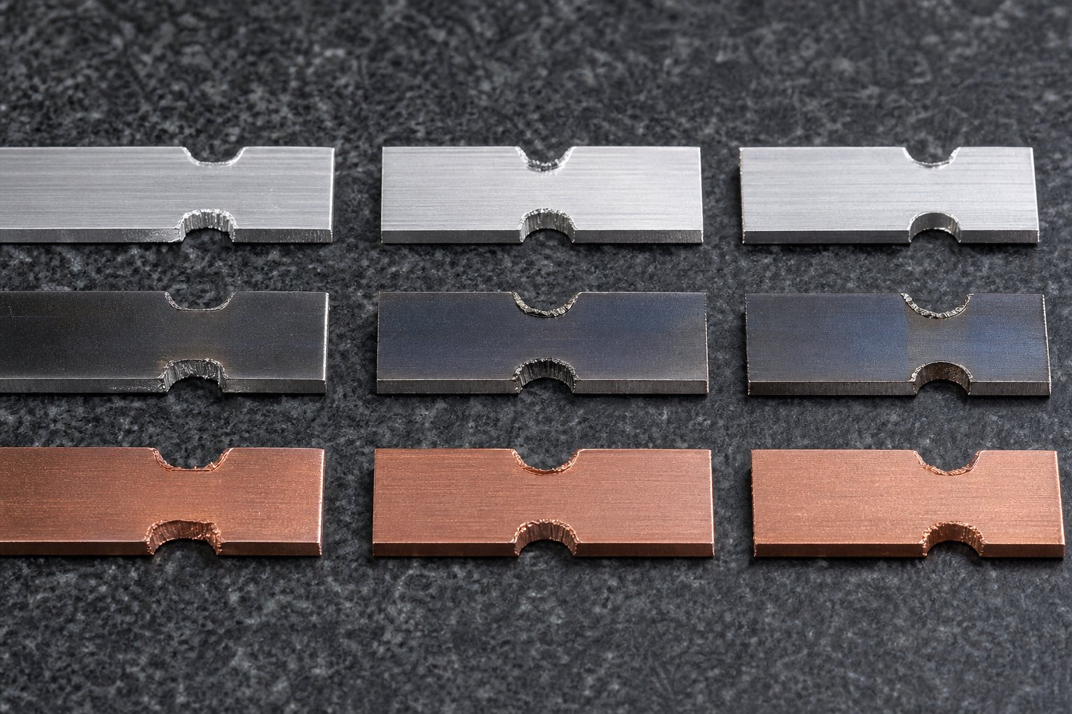
Hardness and ductility control what happens at the notch edges and corners after cutting. Soft, ductile materials like copper and annealed aluminum deform plastically around the notch without cracking. Hard, low-ductility materials concentrate stress at sharp corners and can initiate micro-cracks that propagate under cyclic feeding loads.
Here is how different material categories respond to bypass notch geometry:
- Low-carbon steel (CRS, 1008/1010) - Tolerates sharp V-notch and rectangular geometries well. Good ductility allows stress redistribution at corners. Moderate springback means formed features hold their shape predictably, so notch clearance calculations are straightforward. This is the baseline material for most steel sheet stamping die designs.
- High-strength steel (HSLA, DP, AHSS) - Higher hardness means the notch punch wears faster and cutting forces increase. Reduced ductility makes sharp inside corners dangerous. Rectangular notches in these materials need corner radii of at least 1.0 to 1.5 times strip thickness to prevent fatigue cracking at the carrier edge. Springback is significantly greater, so formed features may project farther than nominal, requiring extra clearance depth in the notch.
- Aluminum alloys (3003, 5052, 6061) - Soft tempers form and cut easily but tend to gall against tool steel punches. The aluminum stamping process demands polished punch surfaces or coated tooling (TiN, DLC) to prevent material buildup on notch punch edges. Aluminum also work-hardens at cut edges, which can make the carrier brittle in the notch zone after repeated load cycles. U-notch profiles with generous radii reduce this risk. Alloys like 6061-T6 are harder but less ductile, behaving more like high-strength steel in terms of crack sensitivity at notch corners.
- Copper and brass alloys - Excellent ductility but prone to work hardening in high-cycle applications. Bypass notches in copper strip typically perform well with any geometry, though the softness of the material means burr formation at the notch edge is more pronounced. Tighter punch-to-die clearances (around 5 to 7 percent of thickness per side) help control burr height.
- Stainless steel (300 and 400 series) - Austenitic grades (304, 316) work-harden aggressively during cutting. The notch edge becomes significantly harder than the parent material, which can lead to cracking if the carrier flexes repeatedly over lifters. Ferritic and martensitic grades are less prone to work hardening but have lower ductility, making them sensitive to stress concentration at sharp notch corners.
Material springback deserves special attention. In the aluminum stamping process and high-strength steel applications alike, springback means formed features do not stay exactly where the punch put them. A bend intended to project 3 mm below the strip plane may spring back to 2.5 mm or push outward to 3.3 mm depending on material yield strength. Notch depth must account for this worst-case projection, not just the nominal formed dimension.
Work hardening at notch edges is a subtler issue that surfaces over time rather than immediately. Each press stroke slightly cold-works the cut edge of the notch. In materials like stainless steel and certain aluminum alloys, this cumulative hardening eventually makes the edge brittle. When the carrier strip flexes over a lifter rail at that hardened zone, micro-cracks form and grow until the carrier fractures mid-run. Selecting U-notch or generously radiused rectangular profiles distributes the bending stress over a wider area and delays this failure mode.
Special Considerations for Coated and High-Strength Materials
Stamped sheet metal increasingly arrives with pre-applied coatings: galvanized zinc layers, pre-painted surfaces, or organic films applied before stamping. These coatings add a constraint that bare metal does not. The notch cutting action shears through the coating at the cut edge, exposing base metal. More importantly, as the strip feeds through the die, the raw notch edges can scrape against guide rails and stop blocks, generating coating debris that contaminates the die.
For galvanized and galvannealed steels common in automotive applications, zinc flaking at notch edges is a known issue. The zinc layer is brittle compared to the substrate and tends to crack and peel away from the sheared edge. Those zinc particles migrate into forming stations and cause surface defects on finished parts. Strategies to manage this include:
- Using slightly larger punch-to-die clearances (8 to 12 percent per side) to produce a cleaner shear with less coating fracture.
- Adding air blow-off stations downstream of the notch punch to clear loose coating particles before they reach forming areas.
- Selecting notch geometries that minimize the total sheared perimeter. A single wide notch creates less cut edge than two narrow notches providing the same clearance volume.
Pre-painted or laminated strips present a different concern. The notch edge itself is not the problem. Rather, any burr or raised material at the cut edge can scratch the painted surface of adjacent strip wraps on the coil or damage the coating during lifter contact. Burr-free notch cutting in these materials requires premium punch-to-die clearance control and frequent punch maintenance to keep cutting edges sharp.
High-strength materials above 980 MPa tensile strength push notch punch tooling to its limits. The cutting force per unit length of notch perimeter increases roughly proportionally with material tensile strength. A notch punch that lasts 500,000 hits in mild steel may need regrinding after 150,000 hits in dual-phase 980 steel. Die designers compensate by using premium tool steels (powder metallurgy grades like CPM-10V or carbide inserts) for notch punches in these applications and by simplifying notch geometry to reduce total cutting perimeter and concentrated stress points.
These material-specific factors do not exist in isolation. They interact with production speed, lubrication choices, and maintenance schedules to determine real-world notch performance. When a bypass notch starts causing problems on the press floor, the root cause often traces back to one of these material interactions rather than a fundamental design flaw.
Troubleshooting Bypass Notch Problems in Production
When a bypass notch starts misbehaving on the press floor, operators often notice the symptom long before they identify the cause. Burrs appear on finished parts. Slugs ride back up into the die. The strip misregisters even though the notch geometry looks fine on paper. These failures rarely happen in isolation. As progressive die troubleshooting research confirms, burr growth, slug pulling, and feeding instability are often symptoms of the same underlying wear progression rather than separate defects. Understanding the root cause behind each symptom is what separates a quick fix from a recurring headache in any precision die stamping operation.
Common Bypass Notch Failure Modes and Root Causes
Imagine your stamping die set running at full speed and suddenly producing mislocated holes at station five. Your first instinct might be to check the pilot pins or feeder timing. But if the bypass notch punch has worn unevenly, the stop reference it creates has shifted. The strip still contacts the stop block, but the contact point is no longer square, allowing the strip to skew slightly before pilots engage. That tiny angular error multiplies across every downstream station.
This is one of the less obvious failure modes. Others are more visible but equally damaging. Here are the primary symptoms operators encounter and the root causes behind each:
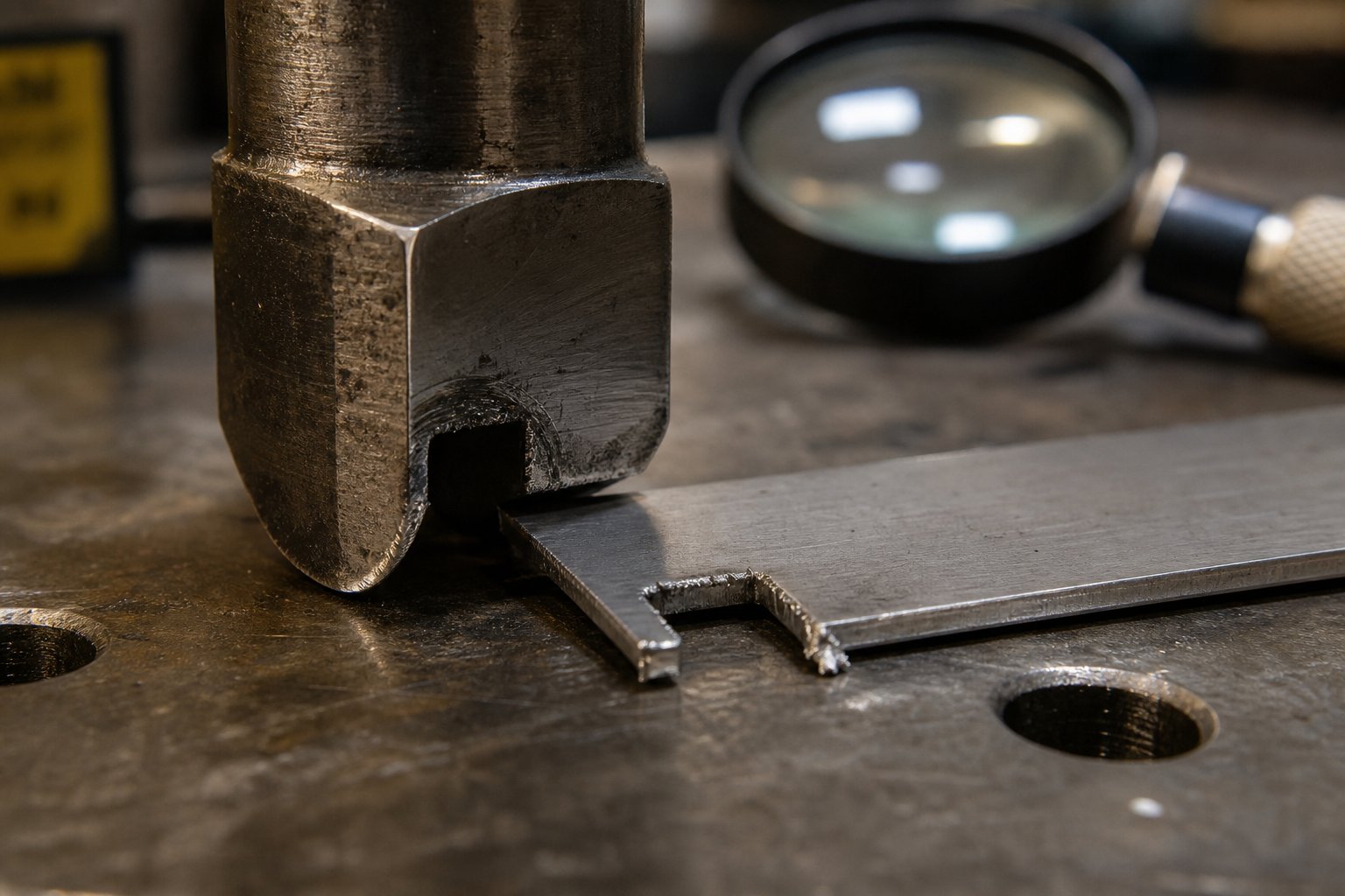
Strip misregistration despite notch presence. The notch exists and contacts the stop, yet parts still show positional drift. Root causes include worn or chipped notch punch edges producing inconsistent notch geometry, a stop block with a worn contact face, or buildup of slug debris on the stop surface. In each case, the reference geometry has degraded even though the system appears functional. The corrective action is to inspect the notch punch edge under magnification, measure the stop block contact face for wear, and clean any accumulated debris from the stop pocket.
Premature notch punch wear. The punch dulls or chips faster than expected for the material and volume. This often traces back to insufficient punch-to-die clearance, which increases shearing force and generates heat at the cutting edge. Running high-strength materials without upgrading to premium stamping die steel (powder metallurgy grades like CPM-10V or M4) accelerates this problem. Corrective actions include verifying clearance per side against material thickness, upgrading punch material for demanding applications, and applying TiN or TiAlN coatings to reduce friction.
Carrier strip fracture at notch locations. The strip breaks at the notch zone during feeding, halting production. This failure points to either excessive notch depth consuming too much carrier width, work hardening at the notch edge from repeated flexing over lifters, or sharp inside corners acting as stress risers in low-ductility materials. The fix involves reviewing notch depth relative to carrier width (staying below 60 to 70 percent), adding corner radii, or switching to a U-notch profile that distributes stress more evenly.
Slug Pulling and Burr Formation at Notch Edges
Slug pulling and bypass notches burr formation in stamping are two of the most common day-to-day issues operators face with notch tooling. They are closely related because both stem from how the punch interacts with the material during cutting and withdrawal.
Slug pulling occurs when the cut slug adheres to the punch face during the upstroke and rides back into the die cavity. At the next stroke, that slug can jam between punch and strip, causing a double-hit or die damage. The underlying mechanics involve vacuum pressure between the punch and slug, combined with surface roughness or oil film on the punch that increases adhesion. Worn punches with slightly concave faces worsen the vacuum effect. Corrective strategies include adding a vacuum relief groove to the punch face, installing spring-loaded slug ejectors, verifying that the die opening allows slugs to fall freely, and ensuring air blow systems are functioning and properly timed.
Burr formation at notch edges develops as the punch dulls. A sharp punch produces a clean shear with minimal rollover. As the edge wears, the material tears rather than shearing cleanly, leaving a raised burr on the strip edge. That burr then drags against guide rails and stop blocks, increasing feeding resistance and accelerating wear on other metal stamping tool and die components downstream. The relationship between clearance and tool life is critical here: deliberately engineered clearances between the punch and die reduce stripping forces while extending tool life and improving edge quality.
The key corrective actions for burr control are maintaining punch sharpness through scheduled regrinding, verifying punch-to-die clearance has not changed due to wear or misalignment, and confirming that stamping die steel grade is appropriate for the production volume and material hardness.
Notch Wear Patterns and Maintenance Intervals
Bypass notch punches wear in predictable patterns that, once you recognize them, tell you exactly what is going wrong inside the die. Edge rounding is the most common pattern: the sharp cutting edge gradually develops a radius that increases burr height and cutting force. Corner chipping appears in harder materials where impact loads exceed the toughness of the punch material. Face wear (a concave depression on the punch tip) develops from repeated slug contact and contributes directly to slug pulling.
How often should you sharpen? There is no universal answer. As Wilson Tool International notes, tool maintenance is as unique as the application itself, with age, material type, speed, and lubrication all influencing the schedule. Waiting until visible burrs appear means wear has already progressed too far. The most reliable approach for precision die stamping operations is to establish sharpening intervals based on stroke count rather than visual inspection alone.
A practical starting framework:
- Mild steel under 1.0 mm: regrind notch punches every 200,000 to 300,000 strokes
- Stainless steel or HSLA: regrind every 80,000 to 150,000 strokes
- Aluminum (galling-prone): inspect every 100,000 strokes for material buildup; regrind as needed
- Coated materials (galvanized, pre-painted): inspect every 150,000 strokes for coating debris accumulation on punch faces
These intervals are starting points. Your actual numbers depend on press speed, lubrication effectiveness, and the specific stamping die steel used for the punch. Tracking burr height with a simple pocket gauge at regular intervals lets you dial in the optimal regrind cycle for your specific application.
The table below organizes the most common bypass notch problems into a quick-reference matrix for press operators and die maintenance personnel:
| Symptom | Likely Root Cause | Corrective Action |
|---|---|---|
| Excessive burr at notch edges | Dull punch edge; insufficient punch-to-die clearance; punch misalignment | Regrind punch; verify and correct clearance; check punch alignment in retainer |
| Slug pulling (slug rides up with punch) | Vacuum between punch and slug; worn concave punch face; inadequate slug ejection | Add vacuum relief groove; regrind flat punch face; install spring ejectors or air blow |
| Strip misregistration at downstream stations | Worn notch punch producing inconsistent geometry; stop block face wear; debris on stop surface | Inspect and regrind notch punch; resurface or replace stop block; clean stop pocket |
| Premature notch punch breakage | Insufficient clearance; punch material too brittle for application; excessive strip thickness variation | Increase clearance; upgrade to tougher punch steel or carbide; verify incoming coil specs |
| Carrier strip fracture at notch zone | Notch depth exceeds safe ratio of carrier width; sharp corners in low-ductility material; work hardening from repeated lifter flexing | Reduce notch depth or widen carrier; add corner radii; switch to U-notch profile |
| Notch slug stacking in die opening | Slug hole too small or misaligned; slug interference from adjacent station geometry; no positive ejection mechanism | Enlarge and align slug hole; verify slug path is unobstructed; add air blow or gravity chute |
| Inconsistent notch depth (varying from hit to hit) | Punch retainer loosening; die block settlement; press shut height drift | Re-torque retainer; verify die block seating; check and reset press shut height |
For shops running high-volume production, YICHEN's custom stamping die solutions address many of these failure modes at the design stage by specifying optimized punch materials, clearance values, and slug ejection paths tailored to the application. Proactive design decisions eliminate recurring maintenance problems that consume operator time during production runs.
Recognizing these failure patterns early and acting on them keeps your stamping die set productive. But the bigger question remains: does every progressive die actually need bypass notches, or are there situations where they can be safely omitted? That decision depends on part complexity, press technology, and the specific strip control demands of your application.
When to Use Bypass Notches and Partnering with Die Design Experts
Not every progressive die demands bypass notches. A flat blanking die running simple perimeter cuts at modest speed faces entirely different strip control challenges than a 20-station automotive stamping die with deep draws, multiple bends, and tight tolerances on stamped metal parts. The decision to include or omit bypass notches should follow a clear engineering rationale rather than habit or assumption.
Decision Framework for When Bypass Notches Are Required
Think of bypass notch necessity as a spectrum driven by four factors: part complexity, forming depth, production speed, and incoming material condition. When multiple factors align toward the high end of that spectrum, bypass notches become essential. When all factors sit at the low end, you may safely omit them.
Scenarios where bypass notches are typically required:
- Multi-station progressive dies with forming operations - Any die that bends, draws, or embosses material at intermediate stations creates features that must clear downstream tooling during feeding. Bypass notches provide the lateral relief these features need to pass without interference.
- High-speed production above 150 strokes per minute - At speed, even small feeding inconsistencies compound rapidly. The mechanical stop provided by a bypass notch prevents cumulative feed error that pilots alone cannot absorb without accelerated wear.
- Wide coil stock or heavy gauge material - Wider and thicker strips carry more momentum during feeding and are harder to stop precisely. The inertia of heavy strip stock makes overfeeding more likely, and a single overfeed event in thick material hits with enough force to damage die components.
- Coil with known edge camber issues - Material from certain slitting sources arrives with pronounced edge waviness. As Art Hedrick notes, bypass notches cut a straight reference edge that removes severe camber and allows smooth feeding regardless of incoming coil condition.
- Dies where operator skill levels vary - In shops with frequent setup personnel turnover, the mechanical overfeeding protection of a bypass notch provides a safety net that no amount of electronic die protection can replace if sensors are bypassed or improperly configured during setup.
Scenarios where bypass notches may be safely omitted:
- Simple flat blanking or piercing dies with no forming - If every station performs only through-thickness cutting operations and no features extend above or below the strip plane, there is nothing to clear and minimal risk of strip lifting.
- Short-run prototype or low-volume tooling - When total production volume stays under 50,000 parts and speed is not critical, the risk exposure from occasional misfeed is low enough to manage with pilot pins and attentive setup.
- Narrow, thin strip stock with reliable edge quality - Thin, narrow strips have low feeding inertia and minimal camber. The feeder can control them precisely, and pilots can correct any small error without overload.
Include bypass notches when your die has forming operations, runs above 150 SPM, uses wide or heavy strip, or depends on operators with varying experience levels. Omit them only when parts are flat-blanked, volumes are low, and incoming material quality is consistently controlled.
How Servo-Press Technology Affects Bypass Notch Requirements
Modern servo-driven presses have reshaped the conversation around strip control. Unlike conventional mechanical presses locked into a fixed crank cycle, servo presses offer programmable ram motion profiles. They can slow the ram during feeding windows, giving the feeder more time to advance the strip precisely. This raises a fair question: does servo technology eliminate the need for bypass notches?
The short answer is no, but it changes the calculus.
Servo presses reduce misfeed risk in specific ways. Their variable-speed profiles allow wider feeding windows at critical points in the stroke cycle, giving CNC feeders more time to accelerate and decelerate the strip accurately. As MetalForming Magazine reports, servo presses require dynamic feeds with high acceleration and deceleration rates, and the feed system must exchange precise timing signals with the press to ensure proper pilot-release sequencing. This level of coordination improves feeding accuracy beyond what conventional mechanical presses achieve.
However, servo technology does not address several problems that bypass notches solve mechanically:
- Edge camber still exists in the incoming coil regardless of press type. No amount of servo control straightens a wavy strip edge.
- First-hit registration during setup still requires a solid stop reference. Electronic synchronization does not help the operator locate the leading strip edge correctly when threading a new coil.
- Formed feature clearance remains a physical geometry problem. A servo press does not make a bent tab smaller or move die steel out of the strip path.
- Die protection during setup - Most progressive die damage occurs in the first 10 hits during die setup, often because die protection is not yet connected or is overridden. A mechanical stop works regardless of whether electronics are active.
The practical impact of servo technology on bypass notch decisions is modest. You might reduce notch depth slightly because improved feed accuracy lowers the probability of extreme overfeeding events. You might choose a positive lance-and-form notch over a slug-producing negative notch because the slower approach speeds reduce impact forces on stop blocks. But eliminating notches entirely on a complex industrial metal stamping die remains risky even with servo control. The mechanical backup they provide costs almost nothing relative to the protection they deliver.
Working with Die Design Specialists for Optimal Strip Control
Bypass notch design sits at the intersection of strip layout optimization, material behavior, forming sequence planning, and production speed requirements. Getting all of these factors right simultaneously is not something a general-purpose CAD operator typically handles. It requires die design experience specifically in progressive tooling for metal stamping components.
When you engage a specialist for automotive stamping dies or other high-complexity progressive tools, the bypass notch conversation should happen early in the design process, not after the strip layout is locked. Notch geometry affects carrier width, which affects material utilization, which affects part cost. Waiting to address notches until after the forming sequence is finalized often forces compromises: either the carrier is too narrow for proper notch depth, or the notch position conflicts with nearby pilot holes.
Experienced die designers evaluate bypass notch requirements as part of the initial strip layout study. They consider formed feature heights at each station, material springback characteristics, target production speed, and the specific press and feeder capabilities in the customer's facility. This holistic approach produces metal stamping dies where every control feature works together rather than fighting for space.
For tooling engineers seeking custom stamping die solutions that incorporate proper bypass notch design, strip layout optimization, and material flow considerations, YICHEN's Stamping Die solutions provide a practical resource. Their approach addresses die structure, component specification, punch design, and clearance optimization as an integrated system rather than isolated decisions. When reviewing any metal stamping dies company overview, look for this kind of integrated design methodology. It indicates a supplier who understands that bypass notch performance depends on everything around it in the die, not just the notch geometry in isolation.
Whether you are building a new progressive die from scratch or troubleshooting feeding problems in an existing tool, the principles remain the same. Define your strip control requirements based on actual production conditions. Select notch geometry and placement that serves those requirements without compromising carrier integrity. And verify that the entire control system, from notch stops to pilot pins to lifters, functions as a coordinated unit at your target speed and volume. That disciplined approach is what separates reliable metal stamping dies from tools that fight you on every production run.
Frequently Asked Questions About Bypass Notches in Stamping Dies
1. What is the purpose of bypass notches in progressive stamping dies?
Bypass notches are engineered relief cuts in the carrier strip of progressive stamping dies. They serve three primary functions: preventing strip overfeeding by creating a mechanical stop reference, providing clearance so formed features can pass through subsequent die stations without interference, and removing edge camber from coil stock to ensure smooth feeding through guide rails. Without them, strips can lift, buckle, or misfeed, leading to die crashes and scrap parts. They work alongside pilot pins, with the notch handling coarse feed control while pilots provide fine X-Y positioning.
2. What is the difference between bypass notches and pitch notches?
The terms are often used interchangeably, but contextual distinctions exist. Pitch notch typically refers to notch geometry specifically tied to pitch advancement and first-hit control, functioning as a solid stop that prevents overfeeding. Bypass notch carries a broader meaning, describing any relief geometry that allows strip material or formed features to pass through or bypass subsequent stations without interference. In many progressive dies, a single notch serves both functions simultaneously. The terminology varies by region and company convention, with North American shops favoring pitch notch and global suppliers more commonly using bypass notch.
3. What are the different types of bypass notch geometries?
Four main configurations exist. V-notches use angled cuts meeting at a point, offering self-centering feed action and working best in thin stock under 2.0 mm. U-notches feature a radiused bottom that distributes stress evenly, ideal for materials prone to work hardening. Rectangular notches maximize clearance area for deep forming stations but need corner radii to prevent cracking. Positive lance-and-form notches retain material by bending it out of the interference zone rather than removing it, eliminating slugs and maintaining carrier rigidity. Selection depends on strip thickness, material properties, clearance requirements, and forming depth at adjacent stations.
4. How deep should a bypass notch be relative to the carrier strip width?
Notch depth should never consume more than 60 to 70 percent of the carrier width. A common starting guideline sets notch depth at 1.5 to 2.0 times the formed feature height to provide working clearance that accounts for material springback and strip misalignment. If formed geometry requires deeper relief than the 60-70 percent ratio allows, the correct approach is to widen the carrier strip in the initial layout rather than pushing the notch deeper. High-strength steels tolerate deeper ratios due to higher yield strength, while soft aluminum or copper alloys need more conservative limits because the remaining carrier deforms more easily under feeding loads.
5. Can servo-press technology eliminate the need for bypass notches?
No. Servo presses reduce misfeed risk by offering programmable ram motion and wider feeding windows, improving feeder accuracy beyond conventional mechanical presses. However, they do not address edge camber in incoming coil, first-hit registration during setup, physical clearance for formed features, or die protection during the critical first hits when electronics may not be active. Servo technology may allow slightly reduced notch depth or favor positive notch designs due to lower impact forces, but eliminating notches entirely on complex progressive dies remains risky. The mechanical backup they provide costs almost nothing relative to the protection delivered.


