


What Are Carbide Stamping Die Components
Imagine running a progressive die at 800 strokes per minute, producing millions of parts per year. At that pace, conventional tool steel punches and buttons wear down fast, dimensions drift out of tolerance, and unplanned downtime eats into margins. That scenario is exactly why engineers turn to carbide.
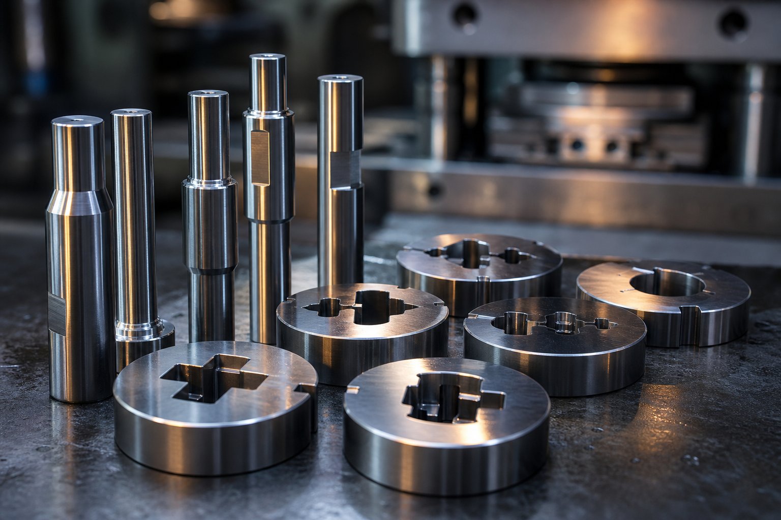
Carbide stamping die components are precision-manufactured tooling elements, such as punches, die buttons, pilots, strippers, and wear plates, made from cemented tungsten carbide (WC) bonded with a metallic binder like cobalt or nickel. They replace conventional tool steel parts inside a stamping die assembly to deliver superior hardness, wear resistance, and dimensional stability across high-volume production runs.
Defining Carbide Stamping Die Components
Cemented carbide is produced through powder metallurgy: tungsten-carbide powder is mixed with a binder, compacted in a mold, and sintered under intense heat and pressure until it forms a solid piece. The result is a material significantly harder than heat-treated tool steel. To put this in perspective, a 6 percent cobalt carbide grade registers approximately 92 HRA, while a tempered tool steel tops out around 62 HRC, a substantially lower hardness value on a comparable conversion scale.
This hardness translates directly into abrasion resistance. In stamping operations that involve forming, punching, and cutting at high speeds, carbide components stay sharp and dimensionally stable far longer than their steel counterparts. Tasks like punching small holes in hard materials may not even be feasible without tungsten carbide tooling.
Where Carbide Fits in the Die Assembly
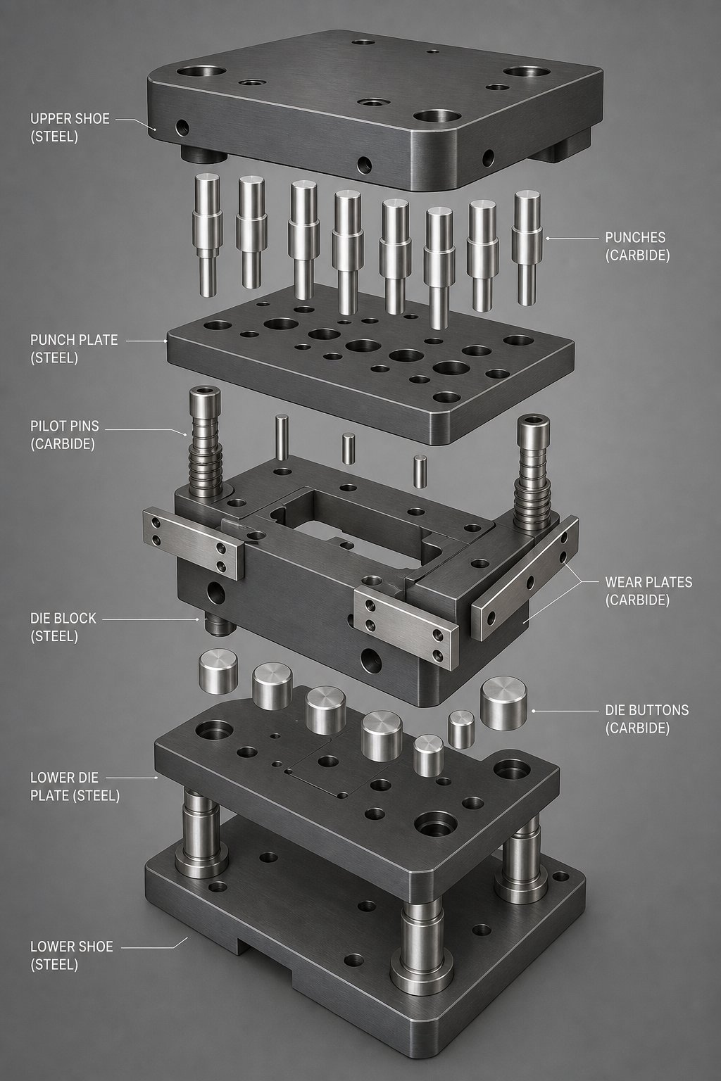
Within a stamping die, carbide does not replace the entire structure. The upper and lower die plates, or shoe, are typically made from medium-carbon steel such as 45 steel, hardened and tempered to 25-30 HRC to provide structural support. Carbide components sit inside this framework as the working elements that contact the strip material directly: the cutting punches, forming inserts, die buttons, pilots that locate the strip, and wear plates that handle sliding contact.
Think of it this way: the steel frame absorbs and distributes press tonnage, while carbide elements handle the actual cutting, forming, and guiding where abrasion and impact are most concentrated. Incorporating carbide inserted punches and buttons into stamping dies keeps tooling sharper for longer periods, which maximizes quality output and can extend tool life by up to 10 times compared to steel.
So why use carbide in die assemblies instead of sticking with tool steel throughout? The answer comes down to production economics. Carbide die components for high volume stamping reduce sharpening cycles, maintain tighter tolerances over longer runs, and minimize scrap from worn tooling. For operations stamping millions of parts, the performance gap between carbide and tool steel is not marginal; it is the difference between profitable runs and constant firefighting on the press floor.
The trade-off is that carbide is inherently more brittle than ductile tool steels. Stress concentrations at sharp corners or improper clearances can initiate cracks that propagate quickly. Successful carbide application depends on matching the right grade, geometry, and support structure to the specific demands of each component position in the die. That selection process, from material properties through grade classification to die-type-specific decisions, is exactly what the sections ahead break down in detail.

Carbide Material Properties That Drive Die Performance
Selecting a carbide component for a stamping die is not a one-size-fits-all decision. The performance you get depends on measurable material properties, and understanding those properties puts you in a position to match the right formulation to each role in the die. Four metrics matter most: hardness, transverse rupture strength (TRS), compressive strength, and density.
Hardness and Wear Resistance in Stamping Environments
Carbide hardness for stamping dies is measured on the Rockwell A (HRA) scale, which is better suited to extremely hard materials than the HRC scale used for tool steel. Across the grades commonly specified for die work, hardness ranges from roughly 82 HRA at the toughest end up to 94 HRA for ultrafine formulations optimized for maximum wear resistance. For context, a 6% cobalt ultrafine grade (0.4 micron grain) reaches approximately 94 HRA with a transverse rupture strength of 3,700 MPa, while a 20% cobalt medium-grain grade sits around 82 HRA with a TRS above 2,600 MPa.
Why does this matter on the press floor? Hardness directly controls abrasive wear resistance. Every stroke of the press drags strip material across the cutting edge or forming surface of a die component. Higher HRA values mean slower material loss at that interface, which translates to longer intervals between sharpening cycles and tighter dimensional consistency across a production run.
Transverse rupture strength measures how much bending force a carbide piece can absorb before fracturing. In stamping, TRS matters for components like slender punches or pilots that experience lateral loading. A grade with 3,700 MPa TRS tolerates significantly more off-axis stress than one at 1,700 MPa, reducing the risk of sudden breakage during high-speed operation. Compressive strength, meanwhile, determines resistance to crushing loads. Carbide grades with finer grains and lower binder content deliver exceptionally high compressive strength, making them suitable for stations where heavy tonnage concentrates on small surface areas.
Density rounds out the picture. Standard cobalt-bonded carbide ranges from about 13.5 g/cm3 at 20% cobalt content up to nearly 15.0 g/cm3 at 6% cobalt. While density does not directly dictate wear behavior, it serves as a quick quality indicator: deviations from the expected density for a given grade can signal porosity or binder distribution issues that compromise field performance.
Binder Content and Grain Size Effects on Performance
Two variables control where a carbide grade lands on the hardness-versus-toughness spectrum: cobalt binder content and tungsten carbide grain size.
Cobalt acts as the "glue" holding the hard WC particles together. Increasing cobalt content improves toughness by adding a ductile metallic phase that absorbs impact energy and resists crack propagation. The trade-off is reduced hardness, because the softer binder occupies more volume. A 6% cobalt grade at medium grain size registers around 91 HRA with a TRS of 1,700 MPa, while bumping cobalt to 15% drops hardness to 86.5 HRA but raises TRS above 2,800 MPa. For die components facing repeated impact, like heavy-gauge blanking punches, that additional toughness prevents catastrophic edge chipping. For wear plates or forming inserts running lighter-gauge material, lower cobalt content preserves the hardness needed to resist gradual abrasion.
Grain size has an equally powerful effect. Finer WC grains pack together more densely, leaving less space for the softer binder to dominate the surface. The result is higher hardness and better edge retention at equivalent binder content. Ultrafine grain carbide wear resistance is substantially higher than that of medium-grain formulations with the same cobalt percentage, which is why precision stamping operations increasingly specify submicron and ultrafine grades for components where edge sharpness and surface finish are critical.
The table below maps the four primary grain size categories to their general performance characteristics in stamping die service:
| Grain Size Category | Typical Grain Range | Relative Hardness | Relative Toughness | Wear Resistance | Best Suited For |
|---|---|---|---|---|---|
| Standard (Medium) | 1.2 - 3.5 micron | Moderate (82-91 HRA) | High | Good | Heavy blanking punches, high-impact dies, cold heading tools |
| Fine | 0.8 - 1.2 micron | High (91-92 HRA) | Moderate-High | Very Good | General-purpose die buttons, forming inserts, progressive die punches |
| Ultrafine / Submicron | 0.4 - 0.8 micron | Very High (92-94 HRA) | Moderate | Excellent | Precision punches, pilots, thin-material cutting, tight-tolerance inserts |
| Nano | Below 0.4 micron | Highest | Lower | Exceptional | Micro-stamping, ultra-precision components, electronic connector dies |
Notice the pattern: as grain size decreases, you gain hardness and wear resistance but sacrifice some fracture toughness. In stamping, this means an ultrafine grade excels where the primary failure mode is gradual wear and edge rounding, while a medium-grain grade is the better choice where shock loading or misalignment risks could trigger brittle fracture.
The practical takeaway for engineers evaluating carbide die components is that no single property tells the full story. A punch that needs to survive millions of hits on thin stainless steel demands a different balance of carbide grain size and edge retention than a die button blanking thick mild steel at moderate volumes. The key is identifying which failure mode you are designing against, abrasive wear or impact fracture, and selecting the binder-grain combination that addresses that specific threat. That decision leads directly to choosing among established grade classifications, each engineered to deliver a particular balance of these competing properties.
Carbide Grades and Their Stamping Die Applications
Grade classifications exist precisely because no single carbide formulation handles every job in a stamping die. The ANSI C-grade system groups cemented carbides by intended service conditions, and understanding that system helps you pick the right chemistry for each position in the die without overpaying or underperforming.
Common Carbide Grade Classifications Explained
The ANSI C-grade system divides tungsten carbide into functional categories. For stamping die work, you will encounter two main families: the C1-C4 straight grades (WC bonded with cobalt, no alloying additions) and the C9-C14 wear and impact grades designed specifically for forming and blanking operations. C5-C8 grades, alloyed with titanium carbide or tantalum carbide for steel machining, occasionally appear in die applications involving ferrous strip materials but are more common in cutting inserts.
Here is how the most relevant grades break down for die component selection:
- C2 (6-10% Co, 90-92 HRA, medium-fine grain): A general-purpose straight grade with high hardness and good wear resistance. Originally specified for machining non-ferrous materials, C2 works well in die components that face abrasive wear with minimal shock, such as wear plates and forming inserts handling aluminum or copper strip.
- C10-C11 (8-13% Co, 88-91 HRA, fine to medium grain): Purpose-built for wear surfaces experiencing light to medium shock. These grades handle blanking and drawing operations and are common choices for die buttons and lighter-duty punches.
- C12-C13 (13-16% Co, 87-89 HRA, medium-coarse grain): Higher cobalt content delivers the toughness needed for heavy forming, coining, and stamping punches that absorb significant impact energy each stroke.
- Micrograin and submicron grades (3-10% Co, 92-95 HRA, grain size below 0.8 micron): These premium formulations pack ultrafine WC particles for maximum edge sharpness and wear resistance. They excel where dimensional precision and surface finish matter most, particularly in pilots, precision punches, and tight-tolerance die inserts.
A critical point that the C-grade numbering can obscure: higher C numbers do not simply mean harder material. As industry references clarify, the classification system groups grades by service type, not by a linear hardness progression. C13 is actually softer than C2 but far tougher, which is exactly what a heavy blanking punch needs.
Matching Grades to Specific Die Components
Grade selection shifts depending on which component you are specifying. A pilot locating a strip at 600 strokes per minute faces entirely different stresses than a die button blanking 2 mm stainless steel. The table below maps carbide grades to component types, connecting the chemistry to functional demands:
| Die Component | Recommended Grade Range | Typical Co Content | Key Performance Attribute | Why This Match Works |
|---|---|---|---|---|
| Precision punches (small diameter, thin material) | Submicron / Micrograin | 3-8% | Maximum hardness, edge retention | Resists edge rounding over millions of hits; maintains hole quality |
| Heavy blanking punches (thick gauge) | C12 - C13 | 13-16% | High impact toughness | Absorbs shock without chipping on heavy-gauge cuts |
| Die buttons (cutting inserts) | C10 - C11 | 8-13% | Balanced wear and shock resistance | Handles repeated shearing stress with moderate impact |
| Pilots and locators | Submicron / Fine grain | 6-10% | Dimensional stability, wear resistance | Maintains tight fit in strip holes across long runs |
| Wear plates and guides | C2 - C10 | 6-10% | Abrasion resistance, low friction | Resists sliding wear from strip progression without shock loading |
| Strippers and specialty inserts | C10 - C12 | 10-15% | Toughness with good wear | Tolerates lateral forces and repetitive contact |
When do micrograin and submicron grades justify their premium over standard formulations? Three scenarios make the cost difference worthwhile: when you are stamping thin materials below 0.5 mm where burr height is tightly specified, when punch diameters drop below 1.5 mm and edge integrity directly determines tool life, or when production volumes exceed several million hits and extended sharpening intervals compound into meaningful downtime savings. In these cases, the submicron grades reaching 93-95 HRA deliver measurably longer service between regrinds.
For everything else, standard and fine-grain grades in the C10-C12 range offer a practical balance. They cost less per blank, they tolerate alignment imperfections better, and they regrind predictably. The smart approach is specifying premium grades only at stations where their specific advantages translate into measurable production gains, not blanket-applying them across every position in the die.
Grade selection, however, only tells half the story. The same C11 grade behaves differently as a round punch versus a contoured die button because geometry, clearance, and loading direction all interact with the material properties. Each component type brings its own set of functional demands and failure modes that shape how that grade performs in practice.
Component-by-Component Carbide Analysis for Stamping Dies
A carbide grade only delivers its rated performance when paired with the correct component geometry, support structure, and clearance setup. Each position in the die imposes unique mechanical demands, and treating carbide as a drop-in replacement for tool steel without adjusting the surrounding design is a fast path to cracked punches and premature failures. Here is what each component type requires.
Carbide Punches and Pilot Components
Punches absorb the most violent forces in any stamping die. Every stroke drives the punch through strip material, subjects the cutting edge to shear stress, and then retracts it through the slug. Carbide excels here because its hardness resists the edge rounding that gradually degrades hole quality in tool steel punches. In certain zero-clearance configurations, carbide punches can maintain burr-free tolerances for up to 10 times longer than their steel equivalents.
Carbide punch design considerations for stamping go beyond material selection. Because carbide is brittle, geometry and support details matter enormously. The failure modes carbide prevents, like progressive edge wear and dimensional drift, can be replaced by catastrophic fracture if the design ignores carbide's limitations.
- Avoid sharp internal corners on punch profiles. Use radii of at least 0.1 mm to reduce stress concentrations that initiate cracks.
- Back punches with a hardened backing plate (56-60 HRC) at least 1.2 to 1.25 times the thickness of a standard steel die backing plate to distribute compressive load.
- Keep punch length-to-diameter ratios conservative. Slender carbide punches amplify lateral deflection, and carbide does not bend before breaking.
- Specify guided stripping to prevent lateral loading during retraction. Unguided stripping is one of the most common causes of punch fracture.
- Use mechanical or hot-sleeve fastening methods. Hot-sleeve assembly exploits the difference in thermal expansion between steel holders and carbide inserts, creating an interference fit at 500-600 degrees Celsius with 0.6-1% interference on diameter.
Pilots face a related but distinct challenge. Their job is strip location, not cutting, so they experience primarily abrasive sliding wear as they enter pre-punched holes at high speed. Carbide pilot components prevent failure modes that plague steel pilots: diameter reduction from abrasive wear leads to strip misregistration, which cascades into dimensional errors across all downstream stations. A submicron carbide pilot maintains its diameter across millions of cycles, keeping station-to-station alignment within specification far longer than hardened tool steel alternatives.
- Specify submicron or ultrafine grades (92-94 HRA) for pilots where strip registration tolerances are tight.
- Design pilot tips with slight tapers or radii rather than flat ends to reduce entry impact forces.
- Ensure pilot holes in the strip are deburred to prevent asymmetric loading on the pilot tip.
Die Buttons and Wear Plates in Carbide
Die buttons are the female cutting elements that receive the punch. They handle the same shearing forces but from the opposite direction, and their cutting edges must resist both abrasive wear from strip passage and the micro-chipping that accumulates at sharp cutting lands. Comparing carbide die buttons vs tool steel buttons, the performance gap is most visible in edge life: tool steel buttons typically need resharpening every 50,000 to 200,000 hits depending on strip material, while carbide buttons in the same application routinely reach 500,000 to over a million hits between service intervals.
The failure mode carbide eliminates here is progressive land wear that opens up the cutting clearance, creates burrs, and forces unplanned shutdowns for sharpening. The failure mode carbide introduces, if poorly specified, is edge chipping from excessive clearance or misalignment.
- Match die button grade to the strip material: harder, lower-cobalt formulations for aluminum and copper; tougher, higher-cobalt grades for stainless steel and high-strength low-alloy materials.
- Maintain cutting clearance within 5-10% of strip thickness per side. Too much clearance creates tensile stress at the cutting edge that carbide tolerates poorly.
- Apply edge chamfers or honed radii to cutting lands. Sharp, unprotected edges are particularly vulnerable to chipping in carbide, and a slight chamfer dramatically reduces fracture risk without affecting part quality.
- Press-fit die buttons into hardened retainers with proper interference to ensure uniform support around the entire circumference.
Carbide wear plates for stamping dies serve a fundamentally different role. They do not cut material; they resist the sliding abrasion of strip movement across guide surfaces and lifter rails. Because wear plates face purely abrasive conditions without impact shock, they are ideal candidates for low-cobalt, high-hardness grades (C2 range, 6-8% Co) that maximize surface hardness. The polished surface finish achievable on carbide also reduces friction and prevents adhesion wear or galling that causes material buildup on steel surfaces.
- Polish wear plate surfaces to a mirror finish (Ra below 0.1 micron) to minimize friction and prevent material transfer.
- Ensure wear plates are fully supported from below; unsupported spans create bending stress that carbide cannot accommodate.
- Use low-cobalt straight grades (6-10% Co) where corrosive lubricants or acidic conditions are present, or consider nickel-bonded grades for improved corrosion resistance.
Strippers and Specialty Inserts
Strippers push the strip material off the punch after each stroke. They experience repetitive contact, lateral forces from strip tension, and occasional impact when strip feeding hesitates. Carbide strippers are less common than carbide punches or buttons, but they earn their place in high-speed progressive dies where steel strippers wear into grooves that snag the strip.
The design priority here is toughness with adequate wear resistance, making C10-C12 grades with 10-15% cobalt the standard choice. The spring-loaded ejector plate should maintain clearance exceeding maximum strip thickness by at least 0.05 mm to prevent impacting the carbide cutting edge during operation.
- Use guided stripper designs with ball-type guide posts to prevent lateral contact with punch cutting edges.
- Specify medium-grain, higher-cobalt grades that tolerate the repetitive impact without micro-fracturing.
- In retrofit scenarios, carbide stripper inserts can replace the contact face of an existing steel stripper without redesigning the entire plate assembly.
That retrofit approach applies broadly. When deciding when to upgrade die components to carbide, you do not always need a complete die rebuild. Individual punches, buttons, pilots, or wear plates can be swapped to carbide independently at stations experiencing the fastest wear or most frequent failures. Start with the components driving your longest downtime events, measure the service life improvement, and expand carbide usage from there based on actual production data.
Each component tells you something about how the die as a whole performs. But the type of die, whether progressive, transfer, or compound, determines which components see the highest cumulative stress and where carbide placement delivers the most return.
How Die Type Shapes Carbide Component Decisions
Not every die burns through tooling at the same rate or in the same locations. A progressive die running connector terminals at 1,200 strokes per minute concentrates wear very differently than a transfer die forming deep-drawn automotive housings at 40 strokes per minute. The die architecture itself dictates where carbide delivers the strongest payoff and where it would be overkill.
Ranked by typical carbide usage intensity, die types fall into a clear hierarchy:
- Progressive dies - highest carbide demand due to extreme stroke counts, multi-station cumulative wear, and tight strip registration requirements.
- Compound dies - moderate-to-high demand because simultaneous cutting operations concentrate stress on a limited number of components that must all maintain edge quality together.
- Transfer dies - selective carbide demand, focused on specific high-wear stations rather than blanket application across the entire tool.
- Combination dies - variable demand driven by which stations perform cutting versus forming, with carbide targeted at the cutting elements.
Progressive Die Carbide Requirements
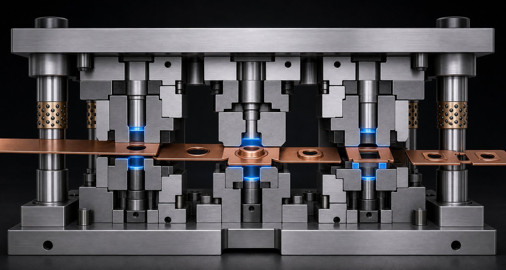
Progressive dies are the workhorses of high-volume stamping. The strip feeds through multiple stations in a single continuous cycle, with each station performing a unique operation. According to industry data, production speeds can reach 1,200 strokes per minute with tolerances under plus or minus 0.001 inch. At those speeds, even minor wear at one station cascades downstream. A pilot that loses 0.01 mm of diameter throws off registration at every subsequent station, compounding dimensional errors across the entire part.
This is why carbide components for progressive stamping dies tend to appear at nearly every critical station. Pilots, cutting punches, die buttons, and strip guides all face relentless cumulative wear. The high stroke rate carbide die selection logic here is straightforward: any component that contacts the strip at speed and must hold a dimension for millions of cycles is a candidate.
Strip progression complexity adds another layer. A 20-station progressive die producing an automotive connector might include piercing, notching, forming, and cutoff stations. The piercing and cutoff stations experience pure shearing stress and benefit from hard, low-cobalt submicron grades. Forming stations, by contrast, need tougher grades that resist the impact of bending operations. Smart carbide placement in progressive dies means grading up or down by station rather than specifying one formulation across the board.
Transfer and Compound Die Considerations
Transfer dies separate the blank from the strip early and move it freely between stations using mechanical transfer systems. This architecture typically runs at lower stroke rates, and each station works on an individual part rather than a connected strip. The result is less cumulative positional wear on pilots and guides because there is no strip to register, but higher localized stress on forming punches and draw inserts that shape complex geometries.
Transfer die carbide placement decisions concentrate on deep-draw punches, trim stations, and any forming inserts that handle high-strength materials. Transfer dies excel with complex geometries and large parts, often in automotive body panel and structural applications where stainless steel or advanced high-strength steel strips accelerate abrasive wear. The guide and transfer mechanisms themselves rarely justify carbide because contact pressures are lower and replacement is simpler.
Compound dies complete multiple cutting operations in a single stroke at one station. Because everything happens simultaneously, every cutting edge in the die must stay sharp together. If one element degrades, the entire part goes out of spec. Compound die carbide requirements lean toward uniform grade selection across all cutting components. A flat washer die with both blanking and piercing elements, for instance, works best with matched carbide inserts so all edges reach their service limit at the same interval, allowing a single regrind event rather than staggered maintenance.
Industry application shapes these decisions further. Automotive stamping die carbide applications often involve high-strength steels and aluminum alloys at volumes exceeding one million parts annually, which pushes progressive and transfer dies toward extensive carbide use in cutting stations. HVAC stamping, meanwhile, frequently involves thinner copper and aluminum at extreme speeds, placing the carbide emphasis on pilots and small-diameter punches that would otherwise wear out in days. The material being stamped interacts with die type to define exactly where carbide investment makes sense, which leads directly to the broader question of whether carbide is cost-justified for a given application at all.
Selecting the Right Carbide for Your Stamping Application
Knowing that carbide outperforms tool steel is one thing. Knowing whether it makes financial sense for your specific job is another. Not every die station needs carbide, and not every production run justifies the upfront premium. The question is not "is carbide better?" but rather "where does carbide pay for itself given what I am stamping, how many parts I need, and what my press is doing?"
Application Variables That Justify Carbide Selection
Five variables interact to determine whether carbide components earn their keep in a given die. Evaluate them together rather than in isolation, because a single favorable factor rarely justifies the investment on its own.
Material being stamped. This is the single strongest driver. Abrasive materials like stainless steel, silicon steel laminations, and high-strength low-alloy steels accelerate tool steel wear dramatically. Carbide selection criteria for stainless steel stamping lean heavily toward submicron grades because the chromium content in the strip acts like fine sandpaper against cutting edges. Softer materials like low-carbon steel, copper, and aluminum are less punishing, but even aluminum can cause adhesive wear (galling) that carbide's polished surface resists far better than tool steel. When evaluating how substrate materials affect tooling choices, YICHEN's materials resource provides a useful starting point for comparing the stamped material properties that influence die component demands across aluminum, steel, stainless steel, brass, and magnesium applications.
Production volume. The production volume threshold for carbide dies typically sits in the range of 500,000 to 1,000,000 total hits for most applications. Below that range, quality tool steel often delivers acceptable life at lower initial cost. Above it, carbide's extended service intervals compound into significant savings from reduced downtime, fewer regrind cycles, and more consistent part quality across the run. High-speed progressive dies running connector pins or electrical contacts at millions of strokes push well past this threshold within weeks, making carbide nearly mandatory.
Press tonnage and strip thickness. Higher tonnage concentrated on small cutting areas creates compressive stress that exceeds tool steel's working limits faster. Thick strip material (above 2 mm in steel) generates proportionally higher shear forces at the cutting edge. Both conditions favor carbide's exceptional compressive strength, but thick-gauge applications also demand tougher grades (higher cobalt) to absorb the impact energy without chipping.
Part complexity. Parts with many closely spaced holes, tight corner radii, or fine features put small-diameter punches at risk. These punches wear faster because less surface area distributes the shearing force. Carbide is often the only practical solution when punch diameters drop below 1.5 mm or when burr specifications are extremely tight.
Use this checklist to determine when to use carbide in stamping dies for a specific application:
- Are you stamping abrasive or high-strength materials (stainless steel, HSLA, silicon steel)?
- Does your total production volume exceed 500,000 parts per die set?
- Are punch diameters below 2 mm or length-to-diameter ratios above 4:1?
- Do current tool steel components require sharpening more than once per 100,000 hits?
- Is unplanned downtime from worn tooling costing more than scheduled maintenance?
- Does your part specification require burr heights under 0.05 mm consistently?
- Are you running stroke rates above 400 per minute continuously?
If three or more of these conditions apply, carbide components will likely deliver a lower cost per part over the production run, even with the higher initial investment.
Retrofit Versus New Build Decisions
Engineers facing a carbide die retrofit vs new build decision have more flexibility than many realize. A full carbide die build makes sense when designing a new tool for a confirmed high-volume program. You can optimize clearances, backing plate dimensions, and holder geometry for carbide's specific requirements from the start, including the thicker backing plates (1.2-1.25x standard) and tighter guide tolerances that carbide demands.
Retrofit is the smarter path when an existing tool steel die is running but underperforming at specific stations. You do not need to rebuild the entire die to gain carbide's benefits. Common retrofit targets include:
- Replacing the fastest-wearing punches with carbide equivalents while keeping the existing punch plate and holder.
- Swapping tool steel die buttons for carbide inserts at cutting stations that drive your sharpening schedule.
- Upgrading pilots to carbide when strip misregistration is causing downstream quality drift.
- Adding carbide wear plates to guide surfaces that show visible grooving or material buildup.
The retrofit approach works because carbide components can often be ground to the same external dimensions as their tool steel predecessors, fitting into existing retainers and holders. The key constraint is ensuring the existing die structure provides adequate support. A carbide punch press-fit into a holder designed for a softer steel insert may need a backing plate upgrade to prevent cracking under load.
Start with data. Track which stations generate the most downtime events and scrap, then target those positions for carbide upgrades first. Measure the service life improvement over two or three sharpening cycles before expanding. This incremental approach limits risk and builds an internal cost-per-part dataset that justifies broader carbide adoption based on your actual production conditions rather than generic estimates.
Whether you choose retrofit or new build, the real payoff from carbide only materializes when you account for its full economic impact across the production lifecycle, not just the purchase order line item.
Total Cost of Ownership for Carbide Die Components
A purchase order for carbide components always triggers sticker shock. The initial price tag can run 3 to 5 times higher than an equivalent tool steel part, and for complex geometries requiring EDM finishing, the multiplier climbs further. That number, sitting alone on a quote sheet, kills carbide projects before they start. But it tells you almost nothing about what the component actually costs over its working life.
Upfront Cost Versus Lifetime Value
Carbide die component total cost of ownership accounts for every dollar spent from the moment a component enters the die until it reaches end of life. That includes the purchase price, yes, but also regrinding costs, press downtime during each maintenance event, scrap generated as edges wear, quality inspection labor tied to dimensional drift, and the opportunity cost of parts not produced while the press sits idle.
Consider what happens with a tool steel die button that needs resharpening every 100,000 hits. Each regrind event means stopping the press, pulling the die, transporting it to the tool room, performing the grind, reinstalling the die, and running first-article verification before production resumes. A carbide button in the same position may run 500,000 to over a million hits before needing service. That is four or more maintenance events eliminated, each carrying its own labor, logistics, and lost-production cost.
The carbide vs tool steel die life comparison becomes even more lopsided when you factor in part quality. As a tool steel edge wears, burr height creeps upward, dimensions shift, and scrap rates climb gradually. You might not catch the degradation until inspection flags a batch, at which point rework or scrapped parts add cost that never appears on the tooling budget line. Carbide's dimensional stability suppresses that creep, holding consistent part quality much deeper into the production run.
| Cost Factor | Tool Steel Component | Carbide Component |
|---|---|---|
| Initial purchase cost | Lower (baseline) | 3-5x higher than tool steel |
| Expected life between regrinds | 50,000 - 200,000 hits (varies by application) | 500,000 - 1,000,000+ hits |
| Number of regrinds before replacement | Multiple, but each shortens life incrementally | Fewer total regrinds needed over equivalent production |
| Maintenance downtime frequency | Higher (more frequent press stops) | Significantly lower |
| Scrap rate trend over service life | Gradual increase as edge wears | Remains stable longer before degradation |
| Part dimensional consistency | Drifts earlier in production run | Holds tolerance across extended runs |
| Specialized service requirements | Standard tool room grinding | Diamond grinding or EDM required |
| Risk of catastrophic failure | Lower (ductile failure mode) | Higher if improperly supported or misaligned |
Calculating Breakeven on Carbide Upgrades
A breakeven analysis for carbide stamping components does not require complicated financial modeling. You need four data points from your current operation: the cost of each tool steel maintenance event (including labor, downtime, and lost production), how frequently those events occur, the scrap and rework costs attributable to edge wear between maintenance intervals, and the total production volume the die must deliver.
The calculation follows a simple structure:
- Total tool steel cost = (initial cost) + (cost per maintenance event x number of events over production life) + (scrap/rework cost attributable to wear)
- Total carbide cost = (initial cost) + (cost per maintenance event x reduced number of events) + (reduced scrap/rework cost)
- Breakeven point = the production volume at which total carbide cost drops below total tool steel cost
The breakeven point arrives faster when any of these conditions intensify: the material being stamped is highly abrasive, downtime costs per hour are high due to press utilization pressure, scrap costs are significant because the stamped material itself is expensive, or the die runs continuously at high stroke rates that compress maintenance intervals into days rather than weeks.
Carbide die reduced downtime cost savings compound over time because each avoided press stop carries a fixed overhead, whether the stop lasts 30 minutes or two hours. On a press line feeding a just-in-time assembly operation, a single unplanned tool change can disrupt downstream schedules far beyond the direct maintenance window. That cascading cost rarely appears in simple tool-life comparisons but dominates the real-world economics.
The honest caveat: carbide does not always win the TCO calculation. Low-volume runs under 500,000 parts, soft strip materials that barely stress tool steel, or prototype dies expected to undergo design changes may never reach the breakeven point. The value of running these numbers is identifying exactly which components in which dies cross the threshold, so you invest carbide dollars where the returns are real rather than assumed.
Getting the economics right, however, only matters if the carbide components actually deliver their rated service life in practice. That depends entirely on how they are handled, maintained, and monitored once they are installed in the die.
Maintaining and Extending Carbide Component Life
A carbide punch rated for a million hits between regrinds will not reach that number if it gets dropped on a steel bench, installed in a misaligned die, or run without adequate lubrication. The material properties are only half the equation. The other half is operational discipline: how you handle, set up, monitor, and service these components determines whether you capture the full return on your carbide investment or burn through it prematurely.
Maintenance and Regrinding Best Practices
Carbide is hard, but it is also brittle. That combination demands a different maintenance mindset than the one most shops apply to tool steel. You cannot muscle a carbide punch into a retainer with a hammer, toss it into a drawer with other tooling, or grind it on a standard aluminum oxide wheel. Each of these shortcuts introduces damage that shortens service life or triggers sudden failure.
Start with handling. Always treat carbide components like precision instruments. Store them individually in padded containers, clearly labeled, and separated so they cannot contact each other or hard surfaces. Even fingerprint oils can create issues over time, so handle with clean gloves and keep storage areas dry to prevent corrosion on any steel portions of the assembly.
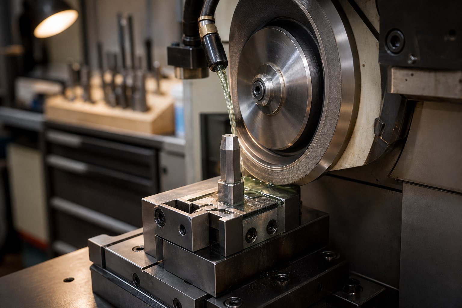
Regrinding carbide stamping punches requires diamond wheels, not conventional abrasives. Carbide's hardness simply destroys aluminum oxide or silicon carbide wheels before they cut effectively. Use a resin-bonded or vitrified diamond wheel with proper coolant flow to prevent thermal cracking. Keep these parameters in mind:
- Remove the minimum material necessary to restore a clean cutting edge, typically 0.02 to 0.05 mm per regrind pass.
- Maintain consistent surface finish across the entire cutting face. Uneven grinding leaves stress risers that initiate edge chipping in service.
- Preserve original geometry exactly. Shear angles, back tapers, and relief features all serve specific functions, and altering them during resharpening eliminates the performance advantages they provide.
- Verify flatness and perpendicularity after grinding. Even 0.01 mm of tilt across a punch face creates uneven loading that carbide tolerates poorly.
- Demagnetize components after any grinding operation to prevent metallic particle adhesion during storage or reinstallation.
Surface finish maintenance extends beyond regrinding. Polished die buttons and wear plates should be re-polished periodically to maintain their low-friction characteristics. Material buildup or micro-scratches from strip passage increase friction, accelerate heat generation, and promote galling. A quick polish with diamond paste during scheduled maintenance events keeps surfaces performing as designed.
Lubrication strategy also plays a direct role in extending carbide die component service life. Proper lubricant creates a barrier film between the strip material and the carbide surface, reducing both abrasive wear and adhesive transfer. Choose lubricants specifically formulated for your strip material and ensure consistent application across the strip width. Insufficient lubrication at one edge of the strip concentrates wear on one side of the die components, creating asymmetric degradation that shortens life and skews part quality.
Alignment verification belongs in every die setup routine, not just during initial installation. Misalignment is a silent killer of carbide die life, causing uneven stress distribution that loads one side of a punch or button beyond its fracture threshold. Use dial indicators to confirm punch-to-die concentricity before running production. A few minutes of verification prevents hours of unplanned downtime from a cracked component.
Wear Monitoring and Replacement Timing
Knowing when a carbide component needs attention is the difference between a scheduled 30-minute regrind and an emergency teardown with scrapped parts in the bin. Carbide does not give the same gradual warnings that tool steel does. Steel edges roll over progressively, producing slowly worsening burrs. Carbide edges tend to hold sharp far longer, then degrade rapidly once wear reaches a critical threshold. That behavior makes proactive monitoring essential.
Watch for these warning signs that indicate a carbide component needs service:
- Burr height exceeding specification on stamped parts, particularly a sudden increase rather than a gradual trend.
- Visible wear bands or polished rings on the cutting land of punches or die buttons.
- Micro-chipping along cutting edges, visible under magnification even if parts still measure within tolerance.
- Increased stripping force or strip lifting issues indicating surface roughening or material adhesion on punch sidewalls.
- Dimensional drift in stamped features, especially hole diameters trending toward the upper tolerance limit.
- Audible changes in press sound during stamping, which can signal developing cracks or loosened inserts.
When you spot these indicators, the question becomes whether reconditioning is viable or the component has reached end of life. Reconditioning works when wear is confined to the cutting face and the remaining component length allows material removal without dropping below minimum functional dimensions. Most carbide punches tolerate multiple regrinds as long as the overall length stays within the adjustment range of the die set. Die buttons, similarly, can be reground on their cutting face multiple times before the land width exceeds acceptable limits.
Replacement becomes necessary when chipping extends below the cutting land into the body, when cracks are visible at any point along the component, or when cumulative regrinds have shortened the piece beyond its usable envelope. Attempting to salvage a cracked carbide component is never worth the risk. Once cracks develop, the die becomes unsafe and must be replaced immediately to prevent catastrophic failure that could damage the die holder, the press, or surrounding components.
Common mistakes that damage carbide die parts and shorten their service life often stem from treating them like tool steel:
- Excessive die clearance. Too much clearance between punch and die button puts the carbide cutting edge in tension during breakthrough, a loading condition carbide handles poorly. Keep clearances within specification and verify them during setup.
- Excessive tonnage. Running more press force than necessary does not improve cut quality but does accelerate compressive fatigue. Size the press correctly for the job and avoid over-tonnage as a workaround for dull tooling.
- Improper stripping. Punches that retract without guided stripping experience lateral forces that cause sidewall chipping. Spring strippers must apply sufficient force to prevent the strip from clinging to the punch during retraction.
- Skipping alignment checks. Even 0.02 mm of misalignment between punch and button creates asymmetric shear loading that concentrates stress on one edge, dramatically increasing fracture risk.
- Incorrect backing plate hardness. A backing plate softer than the punch head allows the carbide to peen into the plate, creating stress concentrations that propagate cracks. Match backing plate hardness to punch head hardness to distribute load evenly.
- Grinding without coolant. Dry grinding generates thermal shock that creates subsurface microcracks, invisible initially but guaranteed to propagate under service loads.
Maintaining detailed service records for each carbide component, including hit counts between regrinds, material removed per service event, and any observed wear patterns, builds the data set you need to predict maintenance timing accurately. Over two or three service cycles, patterns emerge that let you schedule regrinds proactively rather than reacting to quality failures. That predictability is where carbide's total cost advantage becomes operational reality, turning theoretical life extension into actual uptime on the press floor.
Next Steps for Carbide Die Component Selection
Predictive maintenance data, grade-to-component matching, and breakeven calculations all point toward the same conclusion: carbide stamping die components deliver measurable returns when the selection process is driven by application data rather than assumptions. The question for your team is not whether carbide works, but where in your specific dies it pays for itself fastest.
Key Takeaways for Engineers and Sourcing Teams
Every decision covered in this guide reduces to a few core principles. Keep these front and center when evaluating your next carbide investment:
- Grade selection must match the component's dominant failure mode. Abrasive wear calls for low-cobalt, fine-grain formulations. Impact loading demands higher cobalt content and coarser grain structure.
- Die type dictates where carbide earns the highest return. Progressive dies need it broadly across pilots, punches, and buttons. Transfer dies benefit from targeted placement at high-wear forming and trim stations.
- Production volume sets the economic threshold. Most applications cross the breakeven point between 500,000 and 1,000,000 total hits, but abrasive strip materials or high stroke rates pull that number lower.
- Retrofit is a valid path. You do not need a full die rebuild to capture carbide's benefits. Start at the stations driving the most downtime and scrap, then expand based on measured results.
- Maintenance discipline protects the investment. Diamond grinding, proper alignment verification, and proactive wear monitoring are non-negotiable if you expect carbide to reach its rated service life.
Carbide delivers its strongest ROI when you are stamping abrasive materials at high volumes with tight dimensional tolerances, where the cost of each unplanned press stop exceeds the premium you paid for the component that prevented it.
Starting Your Carbide Material Evaluation
Ready to move from research to action? This prioritized sequence gives engineers and sourcing teams a practical carbide stamping die component selection checklist to work through:
- Audit your current die performance data. Identify which stations generate the most regrind events, the highest scrap rates, and the longest unplanned downtime. These are your first carbide candidates.
- Characterize your strip material demands. Review the mechanical properties and abrasiveness of the materials you stamp. YICHEN's materials resource offers a practical starting point for comparing substrate properties across aluminum, steel, stainless steel, brass, and magnesium, helping you understand how your stamped material drives tooling demands.
- Match grade chemistry to each target component. Use the grain size and binder content relationships covered earlier to select formulations that address your specific failure modes, not generic recommendations.
- Run a breakeven calculation for your top three candidates. Plug in your actual downtime costs, maintenance frequency, and scrap data. If the numbers work for those stations, they likely work for others facing similar conditions.
- Specify proper support infrastructure. Confirm that backing plates, retainers, and alignment systems meet carbide's requirements before ordering components. A premium grade installed in an inadequate holder fails faster than tool steel in a proper one.
- Establish a measurement baseline. Document hit counts, part quality metrics, and maintenance intervals from day one so you can quantify the improvement and justify further carbide adoption with real production data.
The engineer guide to carbide die sourcing ultimately comes down to treating each component position as its own engineering problem. The grade, geometry, and support structure that work at one station may be wrong for the next. Let your production data guide the decisions, invest where the returns are proven, and build outward from there. That disciplined, data-driven approach is how you avoid paying twice: once for carbide that fails because it was misapplied, and again for the replacement that finally gets it right.
Frequently Asked Questions About Carbide Stamping Die Components
1. What are carbide stamping die components and why are they used?
Carbide stamping die components are precision tooling elements made from cemented tungsten carbide bonded with cobalt or nickel. They include punches, die buttons, pilots, strippers, and wear plates that replace tool steel parts inside a die assembly. Engineers specify them because carbide registers approximately 92 HRA hardness compared to tool steel at around 62 HRC, providing up to 10 times longer tool life in high-volume production. This extended service life reduces press downtime, maintains tighter tolerances across longer runs, and lowers the cost per stamped part.
2. How do I choose the right carbide grade for my stamping die application?
Grade selection depends on the component's primary failure mode. For punches cutting thin materials or small-diameter holes, submicron grades with 3-8% cobalt and 92-94 HRA hardness provide maximum edge retention. Heavy blanking punches handling thick gauge material need C12-C13 grades with 13-16% cobalt for impact toughness. Die buttons performing moderate shearing work well with C10-C11 grades at 8-13% cobalt. Wear plates benefit from low-cobalt C2 grades optimized for abrasion resistance. Match the grade chemistry to whether you are designing against gradual abrasive wear or sudden impact fracture.
3. When is it cost-effective to use carbide instead of tool steel in stamping dies?
Carbide typically becomes cost-justified when total production volume exceeds 500,000 to 1,000,000 hits. The breakeven arrives faster when stamping abrasive materials like stainless steel or silicon steel, running stroke rates above 400 per minute, using punch diameters below 2 mm, or when unplanned downtime costs exceed scheduled maintenance expenses. Although carbide costs 3-5 times more upfront, its extended service intervals between regrinds, reduced scrap rates, and consistent dimensional output often deliver lower total cost per part over the full production run.
4. Can I retrofit existing tool steel die components to carbide without rebuilding the entire die?
Yes, retrofit is a practical and common approach. Carbide components can be ground to match the external dimensions of their tool steel predecessors, fitting into existing retainers and holders. Start by identifying the stations generating the most downtime and scrap, then replace those specific punches, die buttons, pilots, or wear plates with carbide equivalents. The key requirement is ensuring adequate support infrastructure, particularly backing plates at 1.2-1.25 times standard thickness and proper alignment verification, since carbide demands more rigid support than ductile tool steel.
5. How do I maintain carbide die components to maximize their service life?
Carbide maintenance requires diamond grinding wheels with coolant flow for resharpening, removing only 0.02-0.05 mm per pass while preserving original geometry. Store components individually in padded containers to prevent chipping from contact. Verify punch-to-die alignment with dial indicators during every setup, since even 0.02 mm misalignment concentrates stress and causes fracture. Maintain proper lubrication across the full strip width, keep clearances within 5-10% of strip thickness per side, and monitor for warning signs like sudden burr height increases or visible micro-chipping along cutting edges.


