


What Bypass Notches Do in Progressive Stamping Dies
When you run a progressive die at production speed, every stroke must land in exactly the right place. A strip that drifts even a few thousandths of an inch produces scrap, damages tooling, and shuts down the press. Bypass notches are one of the primary mechanical safeguards against that outcome, yet they receive far less attention than pilots or automatic feed systems in most die design discussions.
This guide covers negative and positive bypass notches in sheet metal stamping dies in full detail, from basic mechanics to selection criteria, material influences, failure modes, and design rules. Whether you call them pitch notches, French notches, or bypass stops, the principles behind choosing positive versus negative geometry determine how reliably your stamping die set performs over millions of cycles.
What Are Bypass Notches in Progressive Dies
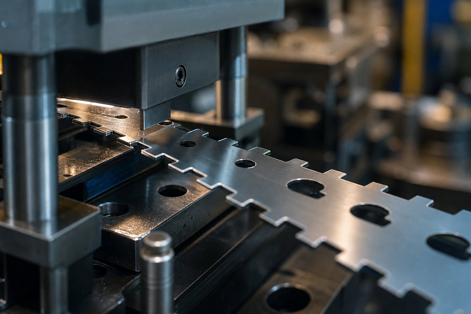
Bypass notches are intentional geometric features cut into or formed onto the carrier strip that engage with corresponding components inside the die. Their purpose is to physically control strip advancement, preventing overfeeding and ensuring each station receives the workpiece at the correct position.
Imagine a strip advancing through a ten-station progressive die. The automatic feeder pushes it forward one pitch per stroke. A bypass notch, whether a tab left on the strip or a pocket cut into the strip edge, meets a mating block or shoulder in the die. That mechanical contact creates a hard stop, a physical limit the strip cannot pass regardless of feeder overshoot or operator error.
How do they differ from pilot holes? Pilots are round pins that enter pre-pierced holes to fine-tune strip position after the feed completes its stroke. They correct small registration errors. Bypass notches, by contrast, prevent gross overfeeding before pilots even engage. A pilot pin sized with 0.0005 to 0.001-inch clearance cannot compensate for a strip that has overshot by half a pitch. That is the job of the bypass notch: hard mechanical constraint of strip travel distance.
Why Bypass Notches Are Critical for Strip Registration
Poor strip registration cascades quickly. Misaligned hits elongate pilot holes, which further degrades registration at downstream stations. Parts drift out of tolerance. Punches contact material in the wrong location, generating uneven side loads that chip cutting edges or snap punches entirely. In severe cases, a single overfeed event can crash an entire die section, resulting in repair costs that dwarf months of material savings.
The purpose of bypass notches in stamping dies extends beyond overfeed prevention. As noted by die design specialist Art Hedrick in The Fabricator, pitch notches also remove edge camber from slit coil stock, creating a clean reference edge that allows the strip to feed smoothly through guides. Without that straight edge, cambered material binds against stock guides, causing erratic feed lengths even with modern servo feeders.
Bypass notches physically constrain strip travel so that each station receives the workpiece in the correct position, independent of feeder accuracy, coil condition, or operator skill level.
Three systems work together for reliable progression: the automatic feeder provides nominal advancement, bypass notches enforce maximum travel limits and remove camber, and pilot pins deliver final precision registration. Removing any one element shifts risk onto the others. When all three function in coordination, the stamping die set maintains repeatability across long production runs, even during setup when most die crashes actually occur.
The critical question for every die designer is not whether to use bypass notches, but which type to use. That decision hinges on whether you leave material on the strip (positive) or remove it (negative), and each geometry carries distinct advantages depending on strip width, production speed, and material behavior.
How Positive Bypass Notches Work and When to Use Them
Leaving material on the strip rather than cutting it away might sound counterintuitive for a feature meant to control progression. Yet that is exactly what a positive bypass notch does, and the geometry behind it solves several problems that conventional slug-producing notches introduce.
How Positive Bypass Notches Control Strip Progression
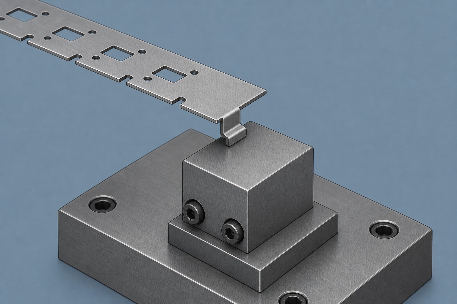
A positive bypass notch is created by lancing a small section of the carrier strip and forming it downward (or occasionally upward) to produce a tab that projects out of the strip plane. Picture a rectangular tongue, typically 3 to 6 mm wide and projecting 1 to 1.5 times the material thickness below the strip surface, oriented perpendicular to the feed direction. The tab remains attached to the carrier at one end, creating a cantilevered flange along the strip edge.
During feed advancement, this formed tab travels forward with the strip until it contacts a hardened stop block or shoulder machined into the lower die shoe. That physical collision halts strip motion at precisely the correct pitch distance. The geometry is self-limiting: the tab cannot pass the stop block, so overfeeding becomes mechanically impossible regardless of how much force the feeder applies.
Why leave material attached instead of punching it out? The answer involves both reliability and strip integrity. A lanced-and-formed tab produces no slug. There is no small piece of scrap that needs to exit through a die opening, no risk of a slug being pulled back up into the die cavity on the return stroke. For anyone familiar with the headaches of slug pulling in punching stamping operations, that advantage alone justifies the approach.
The angular orientation of the tab matters too. Most positive bypass notches are formed at 90 degrees to the strip surface, but slight angular adjustments of 80 to 85 degrees can create a wedging action against the stop block. This increases the holding force and improves feed control on thicker materials where strip momentum is higher.
Typical Applications for Positive Notch Designs
Positive bypass notches in sheet metal forming excel in specific scenarios where strip integrity and scrap management take priority. Consider a narrow carrier strip, say 25 mm wide, feeding a small connector part. Cutting a conventional notch from the edge removes cross-sectional area from an already minimal carrier. That lost material weakens the strip at exactly the point where feed forces concentrate, inviting buckling or tearing during high-speed operation.
A lance-and-form notch avoids this entirely. The material stays in the carrier. Cross-sectional strength remains intact. The formed flange actually stiffens the strip locally, which aids smooth feeding through lifter rails, a benefit noted by die design practitioners working with one-sided carrier layouts.
The purpose of bypass notches in sheet metal forming extends to scrap economics as well. Every slug a die produces adds to material waste calculations. In high-volume production where material cost dominates part pricing, eliminating even a small notch slug from each progression multiplies into measurable savings over a million-stroke run.
- No slug management required - eliminates slug pulling risk and removes the need for slug clearance channels in the die
- Preserves carrier cross-section - critical for narrow strips where material removal would compromise feed stability
- Stiffens the strip locally - the formed flange adds rigidity at the notch location, aiding smooth travel through lifter rails
- Reduces scrap per progression - no material is removed from the strip, improving material utilization on cost-sensitive jobs
- Simpler die construction at the notch station - a lance punch and forming section replaces a full cut-through punch with slug clearance hole
Positive designs do carry constraints. The formed tab must clear lifter mechanisms as the strip rises between strokes. On high-speed dies running above 600 strokes per minute, a downward-projecting tab can catch on lifter rails or interfere with strip elevation timing. These interference risks push some applications toward the alternative: removing material entirely to create a negative notch geometry that engages the die from the opposite direction.
How Negative Bypass Notches Work and Their Strengths
When a formed tab projecting below the strip creates clearance problems at high speed, the solution flips the geometry entirely. Instead of leaving material on the strip, a negative bypass notch removes a small section from the strip edge, creating a pocket that engages a hardened projection built into the die. The strip itself carries the void; the die carries the stop.
Mechanics of Negative Bypass Notches and Material Removal
A negative bypass notch is produced by stamping punching a small rectangular or trapezoidal section from one or both edges of the carrier strip. The stamping die punches used for this operation are typically narrow, ranging from 3 to 8 mm in width and penetrating 2 to 5 mm into the strip edge depending on carrier width and material thickness. The cutting action follows the same shearing mechanics as any blanking operation: the punch descends into a mating die opening, the material fractures through a shear-and-break sequence, and a slug separates from the strip.
That slug demands attention. A notch slug is typically a thin sliver, sometimes as small as two times the material thickness in its narrowest dimension. Shedding such a small piece reliably is a known challenge. The slug clearance hole beneath the die opening must provide adequate draft angle, usually 0.5 to 1 degree per side, to prevent slug stacking. Vacuum assist or positive slug ejection through spring-loaded kickers becomes necessary on high-speed applications where gravity alone cannot clear slugs fast enough.
Once the notch pocket is cut, it advances with the strip until it reaches a hardened key block, a precision-ground steel projection mounted in the die shoe. The key block enters the notch pocket, and the rear wall of the notch contacts the key block face, halting forward strip travel at the correct pitch distance. The geometry here matters: notch depth should exceed key block projection by 0.3 to 0.5 mm to allow clean engagement without binding, while notch width must account for the feed tolerance of the system plus thermal expansion of the strip during long production runs.
Angular relief on the leading edge of the notch, typically 3 to 5 degrees, allows the strip to ride over the key block during feed advancement without catching. The trailing edge remains square or slightly undercut, creating the positive stop face that arrests strip motion. Clearance between the key block sides and the notch walls usually runs 0.05 to 0.10 mm per side, tight enough to prevent lateral drift but loose enough to avoid binding as bypass notches burr formation stamping residue accumulates on engagement surfaces over long runs.
The relationship between notch geometry and burr height is direct. A dull notch punch produces a rollover on the entry side and a pronounced burr on the die side of the cut. That burr projects into the notch pocket, effectively reducing its functional depth. Over thousands of strokes, progressive burr buildup can prevent the key block from fully seating, degrading registration accuracy. Maintaining proper punch-to-die clearance, typically 5 to 10 percent of material thickness per side for mild steel, keeps burrs within acceptable limits and extends maintenance intervals.
Where Negative Notch Designs Perform Best
Negative notches occupy the strip edge rather than projecting below the strip plane. Nothing protrudes. The strip remains flat, which means lifter rails, air blow-off systems, and strip detection sensors all function without interference. For dies running above 600 strokes per minute, this flat profile becomes essential.
Imagine a wide carrier strip, 75 mm or more across, feeding a large automotive bracket. Removing 4 mm from each edge for notch pockets barely affects the carrier's load-bearing cross section. The strip retains structural integrity while gaining aggressive feed control through positive mechanical engagement with the key blocks. The removed material creates a recess that the die's projection enters, essentially building the stop geometry into the tooling rather than into the strip.
This approach also delivers a more decisive stop action. A key block entering a machined pocket engages with full face contact across the notch wall, distributing feed arrest forces over a larger area than a single tab hitting a shoulder. That distributed contact resists deformation better during the sudden deceleration of a heavy strip at speed.
- Flat strip profile - no projecting tabs to interfere with lifters, sensors, or high-speed strip transport mechanisms
- Aggressive feed arrest - full face contact between key block and notch wall distributes stopping forces, reducing localized deformation
- Removes edge camber - the cutting action trims irregular slit edges, producing a clean reference surface for stock guides
- Dual-notch registration - cutting notches on both strip edges and using paired key blocks prevents lateral strip shift during stamping punching operations
- Compatible with high-speed automation - no formed features to catch, bend, or fatigue at elevated stroke rates
- First-hit stop capability - the notch stop serves as a leading-edge locator during initial die setup, reducing the risk of half-hits or loose scrap on startup
The trade-off is clear: negative notches consume strip material, produce slugs that must be managed, and introduce cutting edges that wear over time. For wider strips where those penalties remain manageable, the reliability and speed compatibility of this design make it the dominant choice in high-volume progressive die operations. The question is not which type is universally better, but which set of constraints your specific application imposes, a decision that becomes clearer when the two geometries are placed side by side.
Positive vs Negative Bypass Notches Selection Guide
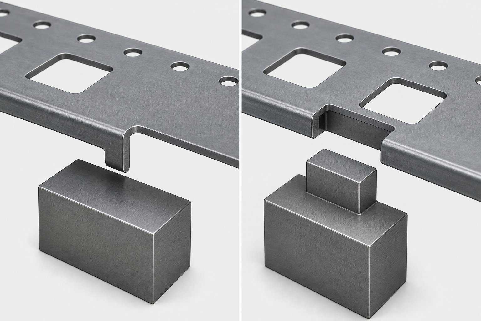
Placing both notch geometries side by side reveals that the choice between them is rarely about one being better than the other. It is about matching the notch design to a specific combination of strip width, production speed, material behavior, and scrap handling constraints. The table below consolidates the mechanical and operational differences into a single reference you can use during tool and die stamping design reviews.
Positive vs Negative Bypass Notches Compared
| Design Dimension | Positive Bypass Notch | Negative Bypass Notch |
|---|---|---|
| Mechanism of action | Lanced tab formed below strip contacts a stop block in the die | Cut pocket in strip edge receives a key block projection from the die |
| Material removal | No - material remains attached to the carrier strip | Yes - a slug is sheared from the strip edge |
| Strip strength impact | Minimal - carrier cross section is preserved; local stiffness increases at the formed tab | Moderate - cross section is reduced at each notch location by the depth of the cut |
| Slug management | None required | Slug clearance holes, draft angles, and possible vacuum or kicker ejection needed |
| Typical strip width range | Narrow to medium strips (under 50 mm) where material removal would compromise carrier integrity | Medium to wide strips (40 mm and above) where edge removal has minimal structural impact |
| Speed suitability | Low to moderate speeds (typically below 600 SPM); tab interference risk increases with speed | Moderate to high speeds (600+ SPM); flat strip profile avoids lifter and sensor interference |
| Burr risk | Low - lance cut produces a controlled fracture on a single edge; no slug exit burr | Higher - shearing action creates burr on die side of cut that can reduce functional notch depth over time |
| Edge camber correction | No - does not remove edge material, so camber from coil slitting remains | Yes - cutting action trims irregular edges, improving strip guidance through stock rails |
| Common failure modes | Tab bending or shearing from excessive feed force; tab interference with lifters; progressive fatigue cracking at lance root | Slug pulling that fills the notch pocket; burr buildup preventing key block engagement; notch edge cracking from work hardening |
Several differentiators in this table carry outsized influence on the final design decision. Strip width is often the first filter. When you are working with a carrier narrower than 30 mm, removing even 3 to 4 mm from the edge for a negative notch consumes a meaningful percentage of the cross section. Feed forces concentrate at the reduced area, and fatigue cracking becomes a real production risk. A positive notch sidesteps this entirely by keeping the material in place.
Speed is the second critical filter. High-speed metal forming operations above 600 strokes per minute demand a flat strip profile. Every millisecond of lifter travel counts, and a tab projecting below the strip can catch, bend, or fatigue in ways that compound rapidly at elevated stroke rates. Negative notches keep everything flush, which is why they dominate automotive and connector stamping lines where cycle times are measured in fractions of a second.
Scrap handling is the third differentiator that often tips the balance. A negative notch produces a slug on every stroke. Over a million-cycle production run, those tiny slivers accumulate. If the slug clearance system fails even briefly, slugs stack in the die opening, block key block engagement, and trigger misfeeds. Shops with excellent slug management discipline absorb this penalty easily. Shops running lean with minimal die maintenance intervals may find positive notches more forgiving.
Edge camber, a frequent headache with slit coil stock, adds another consideration. Negative bypass notches in sheet metal forming stamping dies inherently trim the strip edge, removing camber introduced during coil slitting. Positive notches offer no such correction, so if your incoming material arrives with inconsistent edges, you may need to add a separate trim station or accept the feed instability that camber introduces.
Selection Criteria Checklist for Die Designers
Rather than weighing all factors simultaneously, experienced tool and die stamping engineers work through a sequential decision process. Each criterion either eliminates one option or narrows the field. Use this checklist during strip layout review to arrive at the right notch geometry systematically.
- Strip width and carrier cross section - Measure the available carrier width after part geometry is nested. If the carrier is less than twice the planned notch depth on each side, a positive notch preserves structural integrity. Wider carriers with ample material can tolerate the removal required by negative notches.
- Material type and thickness - Harder materials generate higher burr on negative notch cuts, accelerating key block wear. Thin materials below 0.5 mm risk tearing at formed tabs in positive designs. Match the notch type to how your specific alloy behaves under shear or bending at production temperatures.
- Production speed - If your target exceeds 500 to 600 strokes per minute, bias toward negative notches for their flat profile. Below that threshold, either type performs reliably provided lifter timing accommodates any tab projection.
- Part geometry constraints - Check whether formed features, draw stations, or cam-driven operations near the strip edge conflict with notch location. Positive tabs project below the strip and may interfere with lower die components. Negative pockets sit within the strip plane but consume edge real estate that formed features might need.
- Scrap handling requirements - Evaluate your slug management capability. If the die runs unattended or with minimal operator intervention, a slug-free positive notch reduces one failure mode. If robust slug clearance systems are already in place for other blanking stations, adding notch slugs to the waste stream is trivial.
- Tool maintenance considerations - Positive notch stops are fixed blocks with no cutting edges to resharpen. Negative notch punches require periodic regrinding as burrs grow. Factor your planned maintenance intervals into the decision. Longer intervals between sharpening favor positive designs; shorter, disciplined intervals support negative geometries without issue.
Working through these six criteria in sequence eliminates guesswork. In many cases, the first two filters alone point clearly to one geometry. When the answer remains ambiguous after all six, you are likely in a zone where either type works and secondary preferences such as designer familiarity, shop standard practices, or customer specification take over.
What neither checklist item nor comparison table captures, however, is how to size and position the chosen notch relative to pilots, station spacing, and lifter geometry. The mechanical principle is settled once you pick positive or negative. The dimensional execution, where the notch sits, how deep it cuts, and what clearances it needs, determines whether that principle translates into reliable production or persistent misfeed problems.
Design Guidelines for Bypass Notch Sizing and Placement
Selecting the right notch type is half the battle. The other half is dimensioning and positioning it so the strip stops reliably, stroke after stroke, without over-constraining the feed or starving the carrier of structural material. These sizing rules translate design intent into shop-floor reality.
Rules of Thumb for Notch Depth and Width
Notch depth is the first dimension to pin down, and it scales directly with carrier width. Remove too much and the strip buckles under feed force. Remove too little and the key block engagement becomes shallow enough that burr buildup or thermal expansion defeats the stop within a few thousand strokes.
For negative bypass notches, a common starting point is 15 to 25 percent of the strip width on each side. A 60 mm wide carrier, for example, supports 9 to 15 mm notch pockets cut from each edge while retaining enough cross section for stable feeding. Narrower strips demand more conservative percentages. Below 30 mm of total strip width, you are usually better off with a positive lance-and-form design that avoids material removal entirely.
Notch width, measured in the feed direction, must accommodate the feed tolerance of your system plus a small margin for thermal growth of the strip during production. A typical servo feeder delivering pitch accuracy within 0.05 mm allows a notch width of the key block dimension plus 0.15 to 0.25 mm total. Tighter than that, and the key block binds in the pocket. Wider, and the strip overshoots before arresting.
Corner radii inside the notch pocket deserve attention. Sharp internal corners act as stress risers. Even a modest radius of 0.3 to 0.5 mm at the notch corners prevents fatigue cracking that would otherwise initiate after hundreds of thousands of feed impacts. On hardened tool steels used for key blocks, a matching fillet distributes contact stress more evenly.
Achieving these precise internal geometries, particularly on key blocks and die inserts, is where EDM wire cutting proves indispensable. A skilled tool and die maker can program key block profiles with tolerances of plus or minus 0.0005 inch, producing internal corner radii as small as 0.050 mm with fine wire at controlled speed. Because EDM wire cuts after heat treatment, the key block maintains dimensional stability without distortion from hardening, a critical advantage when the engagement geometry must remain consistent through millions of cycles. Taper relief of 0.25 to 0.5 degrees applied through EDM wire also allows key blocks to be reground without changing the engagement dimension at the working face.
Placement Relative to Station Spacing and Pilots
Where the notch sits along the strip length affects how it interacts with pilots, lifters, and the feed system. A common approach places the notch-cutting station at station one or two of the progressive die, so that every subsequent station benefits from the feed constraint and camber correction the notch provides.
The relationship between notch position and pilot location is sequential, not redundant. Pilots typically engage the strip at station two or three, after the notch has already limited gross overfeeding. As MetalForming Magazine details, the feed roll must release the strip before pilot locating diameters enter the pilot holes. The bypass notch provides the coarse stop that gets the strip within pilot capture range, and the pilot then delivers final precision registration, often correcting the last 0.05 to 0.10 mm of positional error.
Station spacing determines how far the notch pocket or tab travels before engaging the key block or stop. The notch must be cut so its trailing edge aligns exactly one pitch distance from the engagement point. Any error here compounds across stations. If the notch cut is 0.02 mm off from true pitch, that error propagates through every downstream station, creating progressive registration drift that pilots alone may not fully correct.
Lifter interaction adds another constraint. On dies with spring-loaded lifter rails, the strip rises off the die surface between strokes to allow feed advancement. A positive bypass tab projecting below the strip must clear the lifter rail at full lift height. If the tab catches, the strip cannot advance, and the next stroke produces a double-hit. For negative notches, the key block must fully retract below the strip plane before lifters raise the strip, or the notch wall catches the block edge and shears a secondary chip into the engagement pocket.
- Cut notches in the first or second station to establish feed control before forming or blanking operations begin downstream
- Maintain notch-to-pilot spacing at exact multiples of pitch so that both systems reference the same progression baseline
- Verify key block height relative to lifter travel to confirm the block clears the strip during the lift phase and only engages during feed arrest
- Offset notches from stock guide rails by at least 1 mm to prevent interference between the notch edge and the guide channel walls
- Place dual notches symmetrically on both strip edges when lateral control is critical, particularly on wide strips prone to side shift during stamping
- Coordinate notch timing with feed-release signals so the feeder opens before the strip contacts the key block, preventing the motor from fighting the mechanical stop
When both pilots and bypass notches are used together, the tool and die design must ensure the pilot does not fight the notch. If the notch arrests the strip 0.05 mm short of true position and the pilot then drags it forward, the notch wall experiences shear stress against the key block on every stroke. Over time, that repeated loading fatigues the notch edge. The solution is to size the notch so it stops the strip slightly past the pilot capture window, letting the pilot pull the strip back into final position rather than pushing it forward. This subtle directional bias, built into the notch cut location during die construction, eliminates the conflict and extends both notch and pilot life.
For projects where strip geometry, speed requirements, or material behavior push these guidelines to their limits, working with an experienced die engineering partner can prevent costly trial-and-error in the press. Teams at YICHEN specialize in custom stamping die solutions that address the interaction between bypass notches, lifter systems, and precision components such as key blocks and punches, particularly on complex layouts where standard rules of thumb need project-specific validation.
Getting the notch geometry and placement right is ultimately a matter of coordinating mechanical constraints. But those constraints shift depending on what material you are feeding through the die. A notch that performs flawlessly in 1.0 mm cold-rolled steel may crack, deform, or lose engagement when the same die runs 0.5 mm phosphor bronze, a reality driven entirely by differences in how materials respond to the forces bypass notches impose.
Material Properties That Drive Bypass Notch Design Decisions
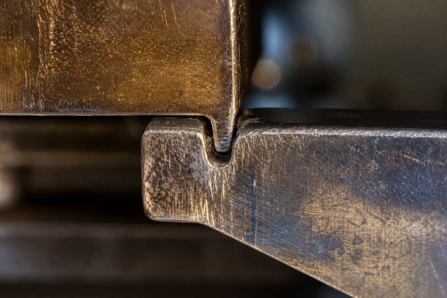
A bypass notch is not just a geometric feature. It is a mechanical interface subjected to repeated impact loading, shear stress, and cyclic deformation every time the strip arrests against the key block or stop. How that interface performs depends entirely on what the strip is made of. Two materials with identical thickness and strip width can demand completely different notch designs based on their yield strength, hardening behavior, and ductility.
How Material Properties Affect Notch Performance
Start with yield strength. Engineered stampings result from plastic deformation caused by forming forces exceeding the material's yield strength, as MetalForming Magazine explains. The same principle governs notch engagement. When a strip contacts a key block at speed, the notch wall experiences a concentrated compressive load. Materials with higher yield strength resist deformation at that contact point, maintaining notch geometry over longer production runs. Softer alloys like annealed copper or aluminum deform progressively, with the notch wall mushrooming slightly on each stroke until engagement depth is lost.
The yield strength of steel varies dramatically across grades. A mild steel at 250 MPa behaves very differently at a notch engagement point than a dual-phase steel at 600 MPa. Higher-strength materials maintain sharper notch edges but also transmit higher impact forces into the key block, accelerating wear on the die component rather than the strip. You are essentially choosing where the wear occurs: on a replaceable strip feature or on a die component that requires maintenance downtime to service.
The elastic modulus of the strip material determines how much springback the notch experiences after the cutting operation. Materials with high elastic modulus, like steel at approximately 200 GPa, spring back less after the notch punch withdraws, leaving the notch pocket closer to its intended geometry. Aluminum, with an elastic modulus around 70 GPa, might seem like it should spring back less due to lower stiffness, but its lower yield strain steel characteristics mean it enters plastic deformation earlier, resulting in a different balance of elastic recovery and permanent set. The practical effect is that notch punch geometry must be compensated differently for each material family to achieve the same final notch dimension.
Strain hardening and work hardening introduce a time-dependent variable that static material properties cannot capture. Every time the strip contacts the key block, the notch wall experiences localized plastic deformation. That deformation strengthens the material at the contact zone. Over thousands of cycles, the notch edge becomes progressively harder and more brittle than the surrounding carrier material. For conventional high-strength low-alloy steels, this strengthening might reach 20 percent above the as-received condition. For advanced high-strength grades like dual-phase steels, rough calculations show that even a few percent strain can increase local strength by 50 percent compared to the flat-sheet properties.
That localized hardening eventually causes cracking. The notch edge, now brittle from work hardening, fractures under the next impact load rather than deforming. Tiny chips break free, contaminating the die and degrading engagement quality. Materials with high elongation values, above 30 percent for mild steels, tolerate more cycles before reaching this failure point because they can absorb repeated deformation without exhausting their ductility. Low-elongation materials like spring steels or fully hardened stainless grades reach the cracking threshold much sooner, demanding either more frequent notch-station replacement or a switch to positive notch designs that distribute feed arrest forces over a larger tab area.
Notch design must account for the material's strain-hardening behavior over the full production run, not just its as-received mechanical properties, because the notch engagement zone strengthens and embrittles progressively with each feed cycle.
Thickness and Strip Width Adjustments
Material thickness directly determines minimum notch engagement depth. A key block must project into the notch pocket deeply enough to prevent the strip from riding over it during feed. For thin materials below 0.5 mm, this means the key block height relative to strip thickness becomes a critical ratio. Too shallow, and the strip flexes over the block. Too deep, and the block contacts the bottom of the notch pocket, creating a secondary shearing action that damages both components.
Thicker materials, above 2.0 mm, generate substantially higher momentum during feed advancement. The kinetic energy the notch must absorb on each stroke scales with both mass and velocity. A 2.5 mm strip at moderate feed speed hits the key block with considerably more force than a 0.8 mm strip at the same speed. Deeper notches with larger contact areas distribute that force, but deeper cuts also remove more carrier material.
Strip width sets the ceiling on how deep a negative notch can safely go. As carrier strip design principles dictate, the carrier must remain strong enough to resist bending during feeding. Removing 25 percent from each edge of a 40 mm strip leaves 20 mm of carrier cross section. On a high-strength steel, that might be adequate. On a soft aluminum alloy with one-third the yield strength, the same geometry buckles under feed force. You need to scale notch depth inversely with material strength: softer alloys get shallower notches and rely more on precise key block geometry than brute engagement depth.
High-strength steels present their own adjustment. The forces required to shear a notch from these grades demand heavier punches, more robust die sections, and tighter clearances to manage the pronounced burr these materials produce. Copper alloys and aluminum cut cleanly with less force but deform at the engagement point. Each material family pushes the notch design in a different direction, and the only universal rule is that no single geometry works across all of them without modification.
These material-driven behaviors do not just affect initial design. They predict how a notch will degrade over time, which failure modes will appear first, and how frequently maintenance is required. That predictive relationship between material properties and failure patterns is exactly what separates proactive notch maintenance from reactive troubleshooting after the die has already produced scrap.
Failure Modes and Troubleshooting Bypass Notch Problems
A bypass notch that works perfectly at stroke one hundred thousand may fail completely by stroke five hundred thousand. The degradation is gradual, driven by the same material behaviors discussed above: localized strain hardening at engagement surfaces, progressive burr accumulation, and cyclic impact forces that fatigue both strip and die components. Recognizing what is failing and why it is failing before scrap starts piling up separates shops that maintain uptime from those stuck in reactive firefighting.
Common Failure Modes for Each Notch Type
Negative and positive bypass notches fail in fundamentally different ways because their mechanics are different. A negative notch relies on a cut pocket and a projecting key block. A positive notch relies on a formed tab and a fixed stop. Each geometry introduces its own wear patterns, and each demands a different diagnostic approach.
For negative notches, the most disruptive failure is slug pulling. The small sliver cut from the strip edge adheres to the punch face during withdrawal and gets carried back up into the die. That slug eventually deposits inside the notch pocket at a downstream station, partially or fully blocking the key block from entering. The strip passes through without arresting, and the next hit lands in the wrong location. Progressive die troubleshooting data confirms that vacuum effects between punch and slug, combined with insufficient clearance or worn ejection systems, are the primary drivers. Spring ejectors, air blow-off, and proper slug clearance drafts reduce the risk, but worn punches with degraded surface finish remain the root trigger.
Burr buildup is the slow-burn failure mode. Each stroke produces a tiny burr on the die side of the notch cut. That burr projects into the pocket, effectively reducing the functional engagement depth by a few microns per thousand strokes. Eventually the key block cannot seat fully, and the stop becomes unreliable. Materials that have been work hardened during prior forming operations, or high-strength grades exceeding 500 MPa yield stress, produce taller burrs and accelerate this degradation.
Notch edge cracking appears on long production runs, particularly in materials prone to strain hardening. The repeated impact of the key block against the notch wall progressively hardens and embrittles that zone. Once the local ductility is exhausted, micro-cracks initiate and propagate. Chips break free from the notch edge, contaminating the die cavity and further degrading engagement quality.
For positive notches, the dominant failure is tab bending or shearing. When the yielding force applied by the strip's momentum exceeds the tab's resistance, the tab deforms forward rather than stopping the strip. This happens when feed speed is too high relative to material thickness, or when the lance root develops fatigue cracks that weaken the tab's attachment point. Once a tab bends even slightly, it no longer contacts the stop block at the correct angle, and each subsequent stroke compounds the deformation.
Tab interference with lifters is a setup-related failure. If lifter rail height is not coordinated with tab projection depth, the tab catches on the rail during strip elevation. The strip cannot advance freely, and the next feed stroke buckles the material between the feeder and the obstruction point. Progressive tab deformation from repeated impacts also changes engagement timing: as the tab mushrooms at its contact face, the effective stop position shifts forward by the deformation amount, introducing a small but cumulative registration error.
| Notch Type | Failure Mode | Symptoms | Root Cause | Corrective Action |
|---|---|---|---|---|
| Negative | Slug pulling into notch pocket | Intermittent overfeed; parts dimensionally long; random misfeed alarms | Punch wear increasing slug adhesion; insufficient slug clearance draft; no vacuum relief | Resharpen or replace notch punch; add spring ejector or air blast; increase die opening draft to 1 degree per side |
| Negative | Burr buildup reducing engagement depth | Gradual dimensional drift on parts; key block marks becoming shallower on strip; increasing misfeed frequency over shift | Punch-to-die clearance worn beyond spec; material yield stress higher than original design assumed; no scheduled regrinding | Restore punch-to-die clearance to 5-10% of material thickness per side; implement stroke-count-based sharpening schedule |
| Negative | Notch edge cracking | Metal chips in die cavity; irregular notch wall visible on strip; sudden loss of registration | Strain hardening at engagement zone over long runs; sharp internal corners acting as stress concentrators; brittle material grades | Add 0.3-0.5 mm corner radii to notch geometry; reduce key block engagement force by optimizing clearance; consider material change or shorter maintenance intervals |
| Negative | Key block wear | Engagement depth decreasing over time; stop position drifting; key block face showing rounding or galling | Insufficient key block hardness relative to strip material; inadequate lubrication at engagement surface; impact forces exceeding design assumptions | Replace key block with carbide-tipped insert; apply TiN coating to engagement face; verify feed speed is within design parameters |
| Positive | Tab bending or shearing | Strip overfeeding; deformed tabs visible on exiting strip; inconsistent part lengths | Feed force exceeding tab resistance; fatigue cracks at lance root; material thickness underspec | Increase tab width or thickness; reduce feed speed; inspect lance punch for wear that thins the tab root |
| Positive | Tab interference with lifters | Strip jamming between strokes; buckling between feeder and die; audible catching sound during strip elevation | Lifter rail height not coordinated with tab projection; tab over-formed beyond design depth | Adjust lifter height to clear tab by minimum 0.5 mm; verify forming depth against print; retime lifter actuation if adjustable |
| Positive | Progressive tab deformation | Parts gradually shifting dimensionally; stop position creeping forward over production run; tab face showing mushrooming | Repeated impact exceeding local yield stress of tab material; work hardened zone becoming brittle and spalling | Harden stop block face to reduce tab deformation; consider heavier-gauge strip if permissible; shorten inspection intervals |
Troubleshooting Strip Misfeeds and Buckling
Die operators rarely see the notch itself failing. What they notice are the downstream consequences: parts that measure inconsistently, strips that buckle between stations, and punches that wear out ahead of schedule. Connecting those symptoms back to the notch system is the diagnostic challenge.
Inconsistent part dimensions, particularly when part length varies by small amounts across a production run, usually indicate registration drift caused by degraded notch engagement. The key block is no longer fully arresting the strip, so each hit lands slightly forward or short of nominal position. Measuring the strip pitch at the notch engagement point, rather than relying solely on part dimensions, isolates whether the registration error originates at the notch or at a downstream forming station. Some high-volume operations integrate an inductive proximity sensor near the key block to detect whether the strip has fully seated against the stop on each stroke, triggering a press halt if engagement fails.
Strip buckling between stations points to an over-constrained feed condition. This occurs when the bypass notch arrests the strip before the feeder has finished its stroke, trapping material between the die and the feed unit. As Peter Ulintz explains in MetalForming, the excess material becomes trapped and buckles as the die opens and lifters raise the strip. The root fix is not to loosen the notch engagement but to retime the feeder release so it opens before the strip contacts the stop. Pneumatic feed systems may require lag time compensation of 35 to 45 milliseconds, depending on press speed, to prevent this over-constrained condition.
Premature tool wear from repeated mis-hits follows a predictable chain: degraded notch engagement allows the strip to land slightly off-position, so punches contact material at incorrect locations, generating uneven side loads. Those side loads accelerate edge chipping and guide wear across multiple stations simultaneously. If you notice accelerated punch wear at several stations at once, the common denominator is almost always a registration issue upstream, and the bypass notch system is the first place to investigate.
Inspection intervals for notch system components should be driven by stroke count rather than visual assessment alone. Notch punches producing negative geometries typically require evaluation every 200,000 to 500,000 strokes, depending on material hardness and clearance conditions. Key blocks should be checked for face wear and galling at the same intervals, with replacement triggered when engagement depth has reduced by 15 to 20 percent from nominal. For positive notch systems, tab projection depth measured on strip samples every 100,000 strokes catches progressive deformation before it compounds into registration drift. An inductive proximity sensor mounted to monitor strip arrival position provides continuous, real-time feedback without requiring manual sample checks, particularly valuable on lines running extended unattended shifts.
Documenting these failure patterns and their corrective actions creates a maintenance knowledge base specific to each die. Over time, that data reveals whether a particular notch design is well-matched to the application or whether a fundamental geometry change, from positive to negative or vice versa, would eliminate recurring failures at their source. That decision loops back into the strip layout and material utilization picture, where notch type and placement influence not just registration reliability but total cost per part.
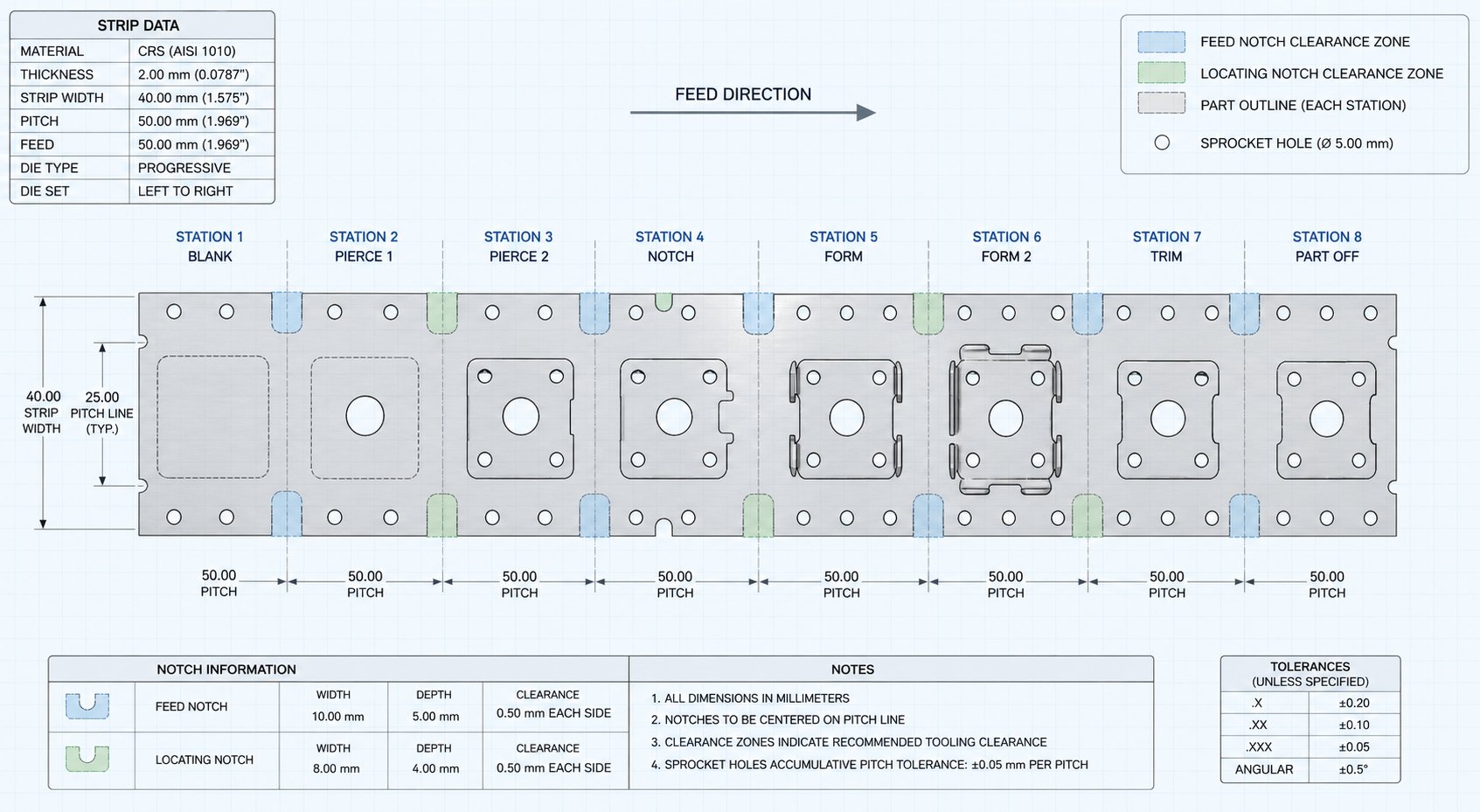
Strip Layout Optimization and Custom Die Engineering Support
Failure mode data feeds directly into strip layout decisions because every notch geometry consumes space, whether physically through material removal or functionally by reserving edge clearance for tabs. That consumed space competes with part geometry for the same strip real estate, making notch design inseparable from material utilization and cost-per-part calculations.
Bypass Notch Impact on Strip Layout and Material Utilization
Consider the arithmetic. A negative bypass notch cutting 4 mm from each strip edge across a 60 mm carrier consumes 8 mm of total width that could otherwise contribute to part nesting. Over a coil yielding 500,000 progressions, those 8 mm translate into significant raw material cost, particularly on expensive alloys like beryllium copper or stainless grades where price per kilogram makes every millimeter count.
Positive notches avoid that width penalty but introduce a different constraint. The formed tab projects below the strip plane, which means the die maker must account for vertical clearance in the lower shoe. That clearance requirement can limit how tightly stations are spaced, occasionally forcing a longer pitch and reducing the number of parts per coil length. In cost-sensitive high-volume runs, even a 2 mm pitch increase per progression compounds across millions of strokes.
Modern material nesting software for length of material optimization validates these trade-offs before any steel is cut. Strip layout platforms model notch geometry against carrier strength requirements, checking whether the remaining cross section can withstand feed forces without buckling. As strip layout design principles confirm, the industry targets at least 75 percent material utilization, and notch design directly influences whether that benchmark is achievable for a given part geometry.
Simulation tools also predict how notch placement interacts with blank nesting. An angular-pass layout that tilts parts for tighter packing may shift the optimal notch location to avoid interference with part features near the strip edge. These interactions are difficult to resolve manually, which is why CAD-based validation has become standard practice. Engineers iterate through notch depth, position, and type within the software environment, comparing material utilization percentages across each configuration before committing to tooling.
The validation workflow typically follows this sequence: define part geometry and nesting orientation, establish carrier width and bridge dimensions, place notch features at proposed locations, run a structural check on the carrier cross section at each notch point, and confirm that key block or stop block positions do not conflict with forming stations or lifter mechanisms. Software flags any configuration where carrier stress exceeds allowable limits, prompting the designer to reduce notch depth, widen the strip, or switch from a negative to a positive notch design that preserves material.
Working with Custom Die Solutions for Complex Notch Designs
Standard design rules handle most applications cleanly. The challenge comes when part geometry, material behavior, or speed requirements push a negative and positive bypass notches sheet metal stamping die into territory where rules of thumb conflict with each other. A narrow strip on a high-speed press at 800 SPM, for instance, needs the flat profile of a negative notch but cannot spare the edge material. A thick high-strength steel demands deep engagement but generates impact forces that crack standard key blocks within weeks.
These edge cases benefit from specialized die engineering support. Teams at YICHEN work with tooling engineers on custom stamping die solutions that address exactly these design conflicts, bringing expertise in die structure, punch and lifter integration, bypass notch optimization, burr control, and material flow to projects where standard approaches fall short.
- Conflicting strip width and speed requirements - when the application demands both a narrow carrier and high-speed flat-profile feeding, requiring hybrid notch geometries or alternative registration strategies
- Aggressive material properties - high-strength or work-hardening alloys that accelerate key block wear or crack notch edges within standard maintenance intervals, requiring specialized coatings, carbide inserts, or geometry modifications
- Multi-row or complex nesting layouts - strip configurations where notch placement must navigate around multiple part outlines, draw stations, and cam-driven operations without compromising registration
- Tight material utilization targets - projects where material cost drives the design and every millimeter of notch depth must be justified against carrier strength calculations validated through simulation
- Extended unattended production runs - dies that must maintain registration reliability across hundreds of thousands of strokes between maintenance, demanding notch and key block designs engineered for maximum wear life
The goal is not to replace the die designer's judgment but to augment it with application-specific engineering when a project exceeds what general guidelines can deliver. Whether the solution involves a geometry change, a material upgrade for die components, or a complete rethinking of the notch and pilot coordination strategy, having access to experienced die maker resources shortens the path from design concept to validated production tooling.
Frequently Asked Questions About Bypass Notches in Stamping Dies
1. What is the difference between positive and negative bypass notches in progressive dies?
A positive bypass notch leaves material on the strip by lancing and forming a tab downward that contacts a stop block in the die. A negative bypass notch removes material from the strip edge, creating a pocket that receives a hardened key block projection from the die. The positive type produces no slug and preserves carrier cross-section strength, making it ideal for narrow strips. The negative type creates a flat strip profile suited for high-speed operations above 600 strokes per minute but requires slug management and reduces the carrier width at each notch location.
2. How do bypass notches differ from pilot holes in progressive stamping dies?
Bypass notches and pilot holes serve different registration functions in a sequential relationship. Bypass notches provide a hard mechanical stop that prevents gross overfeeding of the strip, limiting maximum travel distance regardless of feeder behavior. Pilot holes, by contrast, receive precision pins that fine-tune strip position after the feed stroke completes, typically correcting the final 0.05 to 0.10 mm of positional error. Pilots cannot compensate for a strip that has overshot by half a pitch, which is why bypass notches act as the coarse constraint while pilots deliver final accuracy.
3. When should I use positive bypass notches instead of negative ones?
Positive bypass notches are the better choice when your carrier strip is narrow (under 30-50 mm) and removing edge material would compromise structural integrity, when slug management is a concern due to minimal operator intervention or maintenance schedules, when production speeds remain below 600 strokes per minute, and when scrap reduction is a priority since no material is removed from the strip. They also work well on materials prone to slug pulling, where eliminating the slug entirely removes a common failure mode from the process.
4. What causes bypass notch failures in stamping dies and how do you fix them?
For negative notches, the most common failures include slug pulling that blocks key block engagement, burr buildup that reduces functional notch depth over time, and notch edge cracking from work hardening on long runs. For positive notches, tab bending from excessive feed force and tab interference with lifter rails are primary issues. Corrective actions include resharpening notch punches on a stroke-count schedule (every 200,000-500,000 strokes), maintaining proper punch-to-die clearance at 5-10% of material thickness per side, adding corner radii to prevent stress concentration, and coordinating lifter height with tab projection depth.
5. How do material properties affect bypass notch design in progressive dies?
Material yield strength, strain-hardening tendency, elongation, and thickness all influence notch geometry decisions. Higher yield strength materials maintain notch edge shape longer but transmit greater impact forces into key blocks, accelerating die component wear. Work-hardening materials progressively embrittle at the notch engagement zone, eventually causing edge cracking. Low-elongation materials reach failure sooner and may require positive notch designs that distribute forces over larger tab areas. Thicker materials need deeper engagement to prevent ride-over, while softer alloys like aluminum require shallower notches with tighter key block tolerances to compensate for deformation at the contact point.


