


What Metal Stamping Die Sets Are and Why They Matter
When a stamping die fails, the instinct is to blame the punch, the die button, or the material. But most recurring failures trace back to something less obvious: the die set itself. If the structural framework holding everything in alignment is compromised, every cutting and forming component mounted to it inherits that error. Understanding what a die set actually is, and what it is not, is the first step toward eliminating preventable failures in your press operations.
Defining the Metal Stamping Die Set
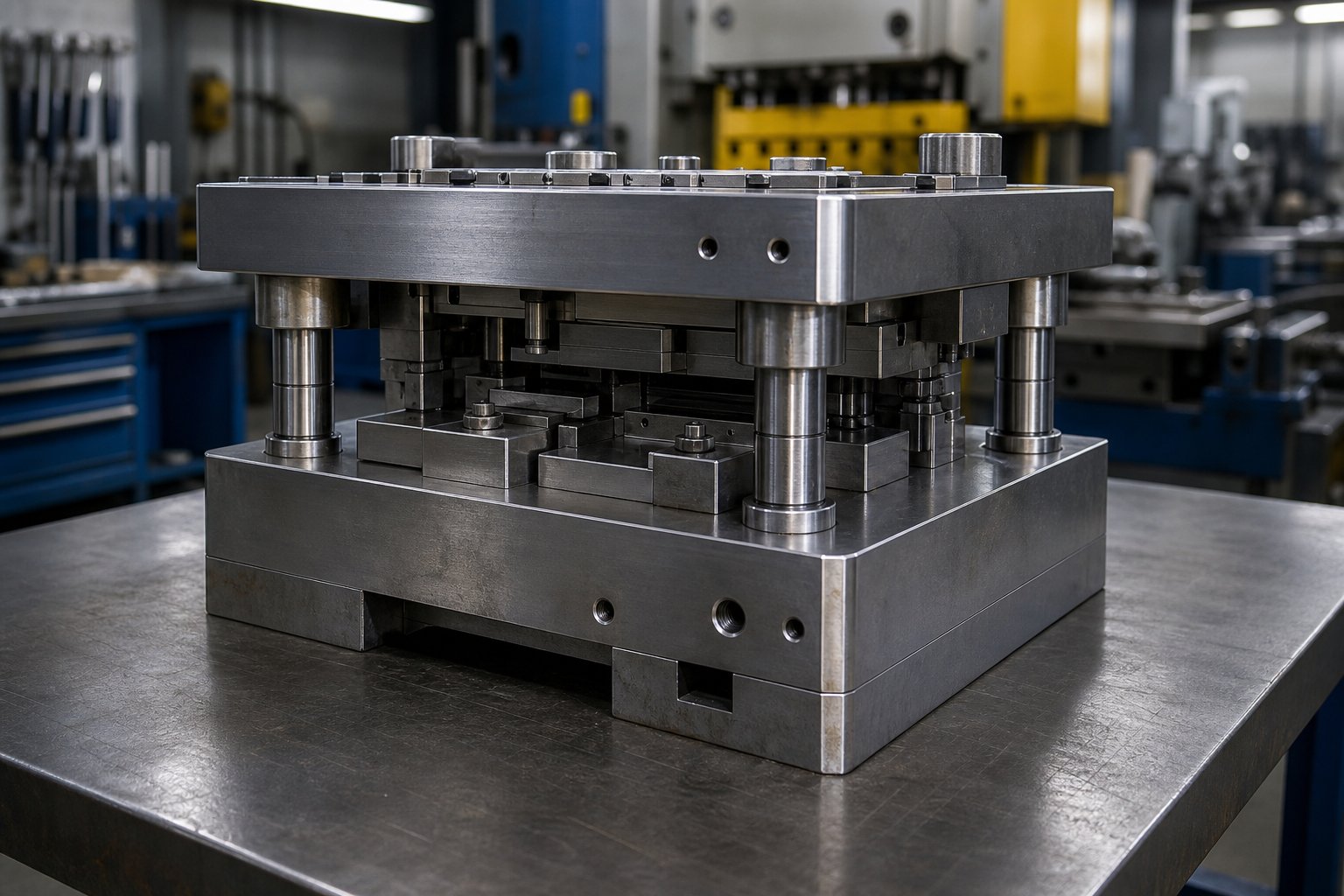
A metal stamping die set is the reusable subassembly of upper and lower die shoes, guide pins, and bushings that holds all cutting and forming components in precise alignment during press operation. It is not the complete stamping die, but rather the structural foundation that provides mounting and repeatable positioning for punches, die buttons, strippers, and other working elements.
This distinction trips up procurement teams and newer press operators more often than you'd expect. The complete stamping die includes every working element, from the stamper dies that cut and form the material to the springs that strip the workpiece. The die set, by contrast, is the skeleton. Think of it as the chassis of a car: it doesn't do the visible work, but nothing functions without it.
A die tool catalog will list hundreds of punch profiles, button styles, and spring ratings. But none of those components perform to specification unless the tool die framework beneath them maintains alignment within thousandths of an inch, stroke after stroke, across millions of cycles. That's the job of the die set.
Why Die Sets Are the Foundation of Every Stamping Operation
Every measurable quality outcome in stamping, positional accuracy of pierced holes, uniformity of bend angles, consistency of blanked edge condition, depends on the upper and lower halves of the die closing in exactly the same relationship every time. The die set governs that relationship through three mechanisms: rigidity (provided by the die shoes), alignment (maintained by guide pins and bushings), and stability under off-center loads.
When any of these mechanisms degrade, the effects cascade. Cutting clearances become uneven, producing burrs on one side of a pierced hole. Forming punches contact the material at a slight angle, causing springback variation. In extreme cases, misalignment leads to galling on guide surfaces or catastrophic interference between upper and lower tooling, a safety hazard for operators and an expensive repair for the shop.
The sections ahead break down every element that makes metal stamping die sets perform or fail: internal components and how they interact as a system, guide system types and when each is appropriate, post configurations matched to specific operations, die shoe material trade-offs, specification and sourcing criteria, troubleshooting the most common failures, and maintenance practices that extend service life. Each section targets a specific decision point that tooling engineers, die designers, and maintenance teams face when building, buying, or repairing these critical assemblies.
The logical starting point is inside the die set itself, where the relationship between shoes, pins, bushings, and heel blocks determines everything that follows.
Essential Components Inside Every Stamping Die Set
Most references to stamping die components read like a parts catalog: a list of names with brief descriptions, no explanation of how those parts depend on each other. That approach leaves engineers guessing when something goes wrong. A die set is not a collection of independent pieces. It is a precision system where each component's performance is defined by its relationship to the others. Understanding those relationships is what separates a properly specified die set from one that delivers chronic quality problems.
Upper and Lower Die Shoes
Die shoes are the machined steel or aluminum plates that form the top and bottom of the die set. Every working element, punches, die buttons, strippers, pilots, mounts directly or indirectly to one of these two surfaces. Their job sounds simple: provide a flat, rigid platform. In practice, the tolerances involved are demanding.
Flatness matters because any deviation in the die shoe surface translates directly into uneven cutting clearance or inconsistent forming contact across the die face. A die shoe that is concave by even 0.001 inches in the center will produce parts with tighter clearance at the middle stations and looser clearance at the edges. The result is variable burr height and accelerated punch wear in localized areas.
Parallelism between the upper and lower die plates is equally critical. As Anchor Danly explains, parallelism is always measured relative to a datum, and it governs how well two surfaces work in relation to each other. In a die set, the datum is the lower shoe's mounting face. If the upper shoe is not parallel to that reference within specification, the press stroke delivers uneven force distribution across the entire die, creating conditions for premature wear, galling, and dimensional drift in stamped parts.
Guide Pins, Bushings, and Heel Blocks
Imagine closing your eyes and trying to place a lid on a box in exactly the same position every time. That is what a press ram does at 200 strokes per minute without a guide system. Guide pins and bushings solve this problem.
Guide pins are hardened steel posts, typically pressed into the lower die shoe. As the press closes, each pin enters a corresponding bushing mounted in the upper shoe, forcing the two halves into precise lateral alignment before any die punch contacts the workpiece. According to Metal Forming Magazine, the guide bushing should engage the guide post at the working level of the die whenever possible, loading the post in shear (its strongest condition) and minimizing deflection that would cause misalignment between upper and lower halves.
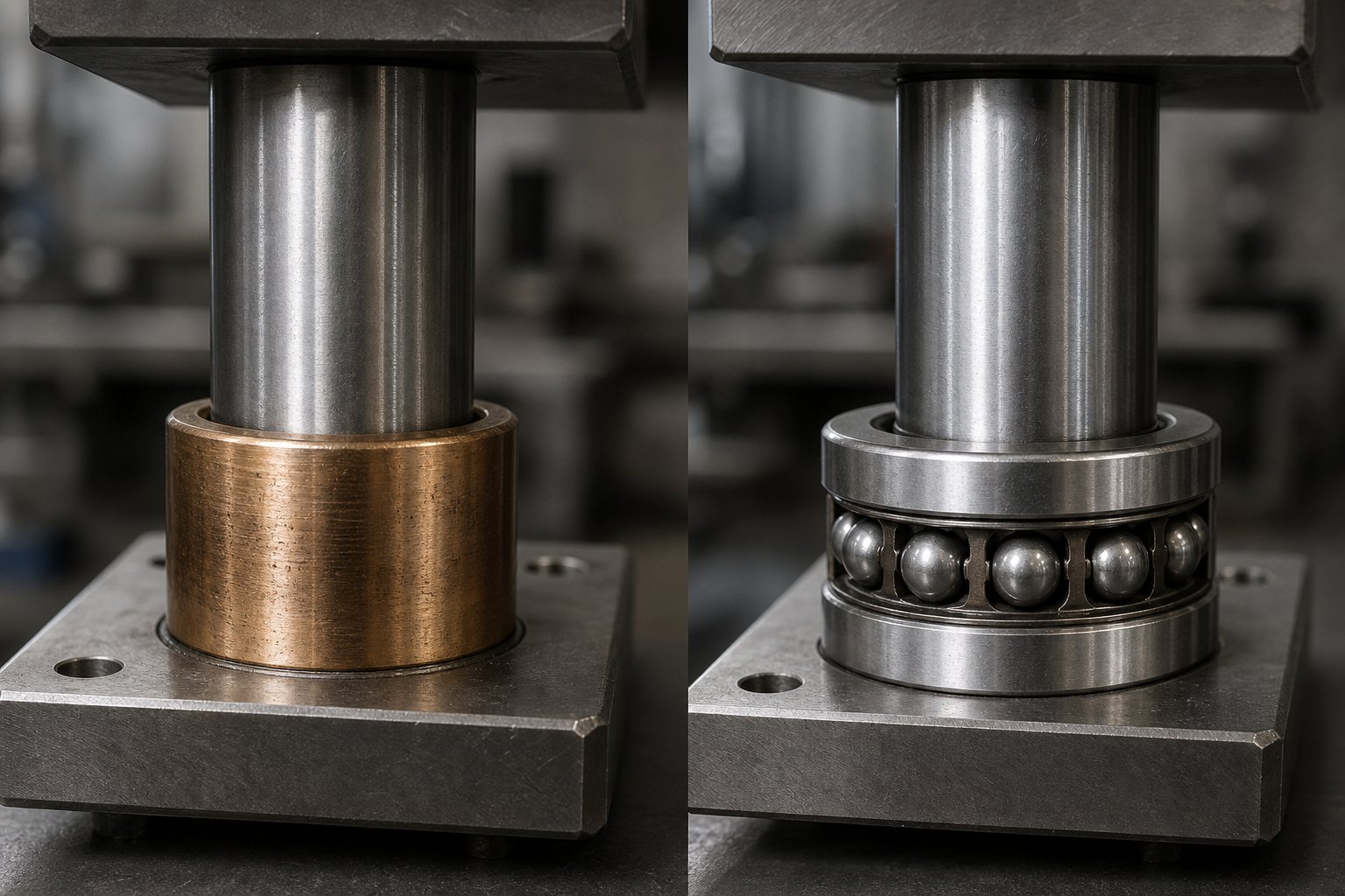
Bushings themselves come in several materials. Bronze-plated steel and solid aluminum bronze, with or without self-lubricating graphite, are the most common for plain bearing systems. The post-and-bushing pair operates with a small running clearance, typically measured in tenths of thousandths of an inch, that defines the maximum possible misalignment during operation.
Heel blocks serve a different purpose. These are wear plate assemblies positioned at the sides or rear of the die set that absorb lateral thrust generated during forming or cutting operations that are not centered on the die. When a stamping operation produces unbalanced side loads, a boxed-heel construction prevents those forces from being transmitted entirely into the guide pins. Some engineers prefer that guide pins engage first to establish alignment, with heel blocks absorbing lateral forces during the working portion of the stroke. The running clearance between heel plate surfaces must be less than the pin-and-bushing clearance for this arrangement to function correctly; otherwise, the guide pins deflect under load before the heel plates take over.
How Components Work Together as a System
Here is where the system-level view matters. Each press die component fills a specific role, but those roles are interdependent:
- Die shoes provide rigidity and flatness, ensuring uniform force distribution across every mounted element.
- Guide pins and bushings provide alignment, controlling the lateral position of the upper die relative to the lower within a defined clearance envelope.
- Heel blocks absorb off-center loads, protecting guide assemblies from forces that would otherwise accelerate wear or cause deflection.
Remove any one function and the others compensate poorly. A perfectly aligned guide system mounted to a deflecting die shoe still produces misalignment under load. Rigid shoes with worn bushings still allow lateral drift. And without heel blocks on a die with asymmetric forming loads, even new guide pins will develop galling marks within thousands of strokes.
The table below maps each component to its primary function, typical material, and the specific quality outcome it controls in the finished part:
| Component | Primary Function | Typical Material | Quality Outcome Controlled |
|---|---|---|---|
| Upper Die Shoe | Rigid mounting platform for punches and upper tooling | A36 steel, 4140 steel, or 7075 aluminum | Uniform cutting clearance and forming contact |
| Lower Die Shoe | Rigid mounting platform for die buttons and lower tooling | A36 steel, 4140 steel, or 7075 aluminum | Consistent shut height and force distribution |
| Guide Pins | Lateral alignment of upper and lower halves | Hardened alloy steel (58-62 HRC) | Positional accuracy of pierced holes and trim edges |
| Guide Bushings | Precision bearing surface for guide pins | Bronze, aluminum bronze, or ball-bearing assembly | Repeatability of alignment across production run |
| Heel Blocks | Absorb lateral thrust from off-center loads | Hardened tool steel wear plates | Prevention of guide pin deflection and uneven wear |
This system-level understanding changes how you approach failures. When a die produces inconsistent burr on one side of a blanked part, the instinct is to adjust cutting clearance at the die punch and button. But if the root cause is a worn bushing allowing 0.0005 inches of lateral play, adjusting clearance is a temporary patch. The play remains, and the problem returns within a few thousand hits. Recognizing that stamping die components interact as a system points you toward the actual failure source rather than its symptom.
The guide system deserves deeper attention because it is the single largest variable in die set performance and cost. Two fundamentally different bearing technologies, plain and ball bearing, offer very different trade-offs in precision, speed capability, and maintenance demands.
Plain Bearing vs Ball Bearing Guide Systems Compared
The guide system is where die set performance either holds or falls apart. Two fundamentally different technologies compete for the role, and picking the wrong one costs more than the price difference between them. It costs you in burrs, dimensional drift, unplanned downtime, and the slow erosion of confidence in parts coming off the press. The choice between plain bearing and ball bearing guidance is application-driven, not a matter of one being universally better than the other.
Plain Bearing Guide Posts Explained
A plain bearing guide system is straightforward: a hardened steel guide pin slides directly inside a bushing with a small running clearance between the two surfaces. Bushings are typically bronze-plated steel, solid aluminum bronze, or graphite-impregnated bronze that provides self-lubricating properties. The design has been the backbone of press die set configurations for decades, and for good reason.
The advantages are practical. Plain bearing systems cost less, occupy a compact envelope that fits tight die layouts, and tolerate conditions that would destroy rolling-element assemblies. Slight misalignment, contamination from airborne grit, rough handling during die changes, even intermittent side loading from off-center forming operations - plain bearings absorb this kind of abuse more predictably. As Anchor Danly notes, plain bearing sets fail more predictably when abuse shows up, and they don't have rolling elements that can Brinell, spall, or get contaminated by debris.
The trade-offs are equally clear. Sliding friction generates heat at higher stroke rates, which accelerates wear and can cause stick-slip behavior if lubrication is inconsistent. A hydraulic press die set running at modest speeds may never encounter this limitation. But push a plain bearing system to 200-plus strokes per minute on a mechanical press, and you'll notice rising guide temperatures, accelerated bushing wear, and eventually galling marks that signal the system is operating beyond its comfortable range. Periodic re-lubrication is non-negotiable - too little invites galling, too much attracts fines that turn into lapping compound between the sliding surfaces.
Ball Bearing Guide Post Assemblies
Ball bearing guide systems replace the sliding contact with rolling elements. A ball cage wraps around the guide post OD, and the bearings roll between the post and the bushing ID under a preloaded condition. That preload, typically ranging from 0.0001 to 0.0021 inches depending on manufacturer specifications, eliminates running clearance entirely. The result is near-zero friction, minimal heat generation, and alignment repeatability that plain systems cannot match at production speeds.
For a punch press die set running high-speed progressive work, ball bearing guidance earns its premium. The friction reduction keeps the guide system thermally stable across long production runs where the press never really cools down. Alignment stays consistent whether you're on hit 100 or hit 100,000 within the same run. And because rolling contact produces far less wear debris than sliding contact, service intervals stretch significantly compared to plain bearing equivalents.
But ball bearing systems come with strict rules. They do not tolerate shock loads well - a misfeed or slug stack can Brinell the raceways, creating dents that produce "notchy" travel and progressive alignment drift. Contamination is equally punishing. Unlike plain bushings that can embed small particles, rolling elements redistribute debris into the bearing path, accelerating damage with every stroke. Side loading from heavy forming operations or angular cam work transfers directly to individual ball bearings in point contact, causing tracking marks that dig into the guide post OD or bushing ID.
You'll also encounter cage creep in some applications - a condition where the ball cage drifts from its designed position during the stroke, eventually causing bearings to skid rather than roll. This generates heat, flat-spots bearings, and accelerates wear. The fix is mechanical: a positive stop or bumper that resets the cage position at the bottom of each stroke.
Choosing Between Plain and Ball Bearing Systems
Production volume and stroke speed are the primary drivers, but they are not the only factors. The honest question, as experienced toolmakers put it, is this: what are you asking the die set to forgive? A sheet metal punch and die set in a clean, climate-controlled facility running dedicated long production runs is a textbook ball bearing application. The same tooling traveling between presses in a shop with winter grit on the floor and a lubrication schedule that depends on whoever remembers first - that's where plain bearings survive and ball bearings get expensive fast.
The table below frames the decision across the criteria that matter most when specifying die sets for press applications:
| Criteria | Plain Bearing System | Ball Bearing System |
|---|---|---|
| Precision Class | Commercial (standard running clearance) | Precision (preloaded, zero clearance) |
| Max Recommended Stroke Rate | Up to ~150 SPM (application-dependent) | 300+ SPM with proper maintenance |
| Maintenance Interval | Re-lubricate every run; bushing inspection frequent | Oil lubrication at specified intervals; longer service life |
| Relative Cost Index | 1x (baseline) | 1.5x–2.5x depending on size and preload class |
| Side Load Tolerance | Good - fails predictably under abuse | Poor - causes Brinelling and tracking damage |
| Contamination Resistance | Moderate - embeds small particles | Low - rolling elements redistribute debris |
| Ideal Application | Short-run, prototype, heavy forming, dirty environments | High-volume progressive stamping, tight-tolerance blanking |
Notice how precision class connects directly to achievable part tolerances. A plain bearing system with 0.0004 inches of running clearance means your punch dies for press operations can shift laterally by that amount on every stroke. For coarse-tolerance blanking, that's acceptable. For a progressive die holding hole-position tolerances of plus or minus 0.002 inches across eight stations, that cumulative play becomes the limiting factor - and a ball bearing hydraulic press die set with zero running clearance eliminates it entirely.
The real cost comparison isn't the purchase price. It's the downstream consequence of mismatching the guide system to the application: chasing alignment problems, replacing punches prematurely, managing mystery burrs that move station to station, and absorbing downtime that dwarfs the original price difference between the two systems.
Guide system type controls precision and speed. But a separate decision, one that affects access, feeding direction, and load distribution, determines where those guides sit on the die shoes. That's the post configuration question, and it's more consequential than most engineers give it credit for.
Die Set Post Configurations and When to Use Each
Where your guide pins sit on the die shoes is not a catalog default you skip past. Post configuration dictates how strip material enters the die, which sides remain accessible for operator intervention, and how well the set of die shoes resists deflection under asymmetric loads. Pick the wrong arrangement and you create feeding obstructions, maintenance headaches, or alignment problems that no amount of bushing upgrades will solve. Four standard die configurations cover the vast majority of stamping applications, each with a distinct geometric logic.
Back-Post Die Sets and Front-Feeding Clearance
Back-post die sets position both guide pins along the rear edge of the die shoes. This leaves the front and both sides completely unobstructed - exactly what progressive stamping demands. Strip material feeds from one side across the die face and exits the other without ever encountering a guide post in its path. Operators gain clear sightlines to the strip, easy access for misfeed correction, and room for auxiliary equipment like sensors or air-blow systems.
This is the most common stamp die set configuration in shops running coil-fed progressive work. Danly die sets, among the most widely specified in North American toolrooms, are available in back-post arrangements precisely because progressive stamping dominates high-volume production. The trade-off is structural: with both posts on one edge, the die set is less resistant to front-to-back rocking under heavy loads compared to configurations that distribute guide points more broadly.
Center-Post and Diagonal-Post Configurations
Center-post die sets place the guide pins at the midpoints of opposite edges, creating a balanced geometry that distributes alignment forces symmetrically. This makes them well suited for blanking and compound operations where cutting forces act more or less uniformly across the die face. The centered placement resists twisting and provides consistent alignment regardless of where on the die the workload concentrates.
Diagonal-post sets split the difference. Pins sit at diagonally opposite corners, which maintains reasonable feeding clearance along one edge while improving rigidity compared to a back-post layout. When you need better load distribution than back-post provides but can't justify the cost and complexity of a four-post stamping die set, diagonal placement is the practical middle ground. Many anchor danly die sets are available in diagonal configurations for exactly this reason - they serve medium-volume operations where neither pure access nor pure rigidity dominates the specification.
Four-Post Die Sets for Maximum Rigidity
Four-post configurations place a guide pin at each corner of the die shoes. The result is the highest achievable alignment accuracy and maximum resistance to deflection from off-center or heavy tonnage loads. Large compound dies, transfer dies, and any application where the stamping forces are severe or asymmetric benefit from this arrangement.
The cost is access. With posts at all four corners, strip feeding requires threading through the guide posts, and operator access to the die interior is restricted. That's an acceptable trade-off for large-format dies that don't require frequent manual intervention and where a superior die set performance under load outweighs convenience. Four-post die sets for presses handling transfer operations are essentially the standard die configuration at tonnages above 200 tons.
The following list summarizes each configuration against its primary advantage and best-fit application:
- Back-post: Unobstructed front and side access. Best for progressive stamping with coil-fed strip material.
- Center-post: Symmetrical load distribution. Best for blanking and compound dies with balanced cutting forces.
- Diagonal-post: Balanced rigidity with partial feeding clearance. Best for medium-volume work requiring moderate access and improved stability.
- Four-post: Maximum alignment accuracy and deflection resistance. Best for large compound dies, transfer dies, and high-tonnage operations.
Rule of thumb: match the post arrangement to the feed direction first, then to the load distribution second. Access determines feasibility; rigidity determines longevity.
Post configuration is not cosmetic. It is a functional decision that interacts directly with guide system type, die shoe dimensions, and the forces your press delivers. A back-post set with ball bearing guides is a different animal than a four-post set with plain bearings - each optimized for a different production reality. But neither configuration performs to its potential unless the die shoes themselves are made from the right material for the application's tonnage, weight, and thermal demands.
Die Shoe Materials and Their Performance Trade-Offs
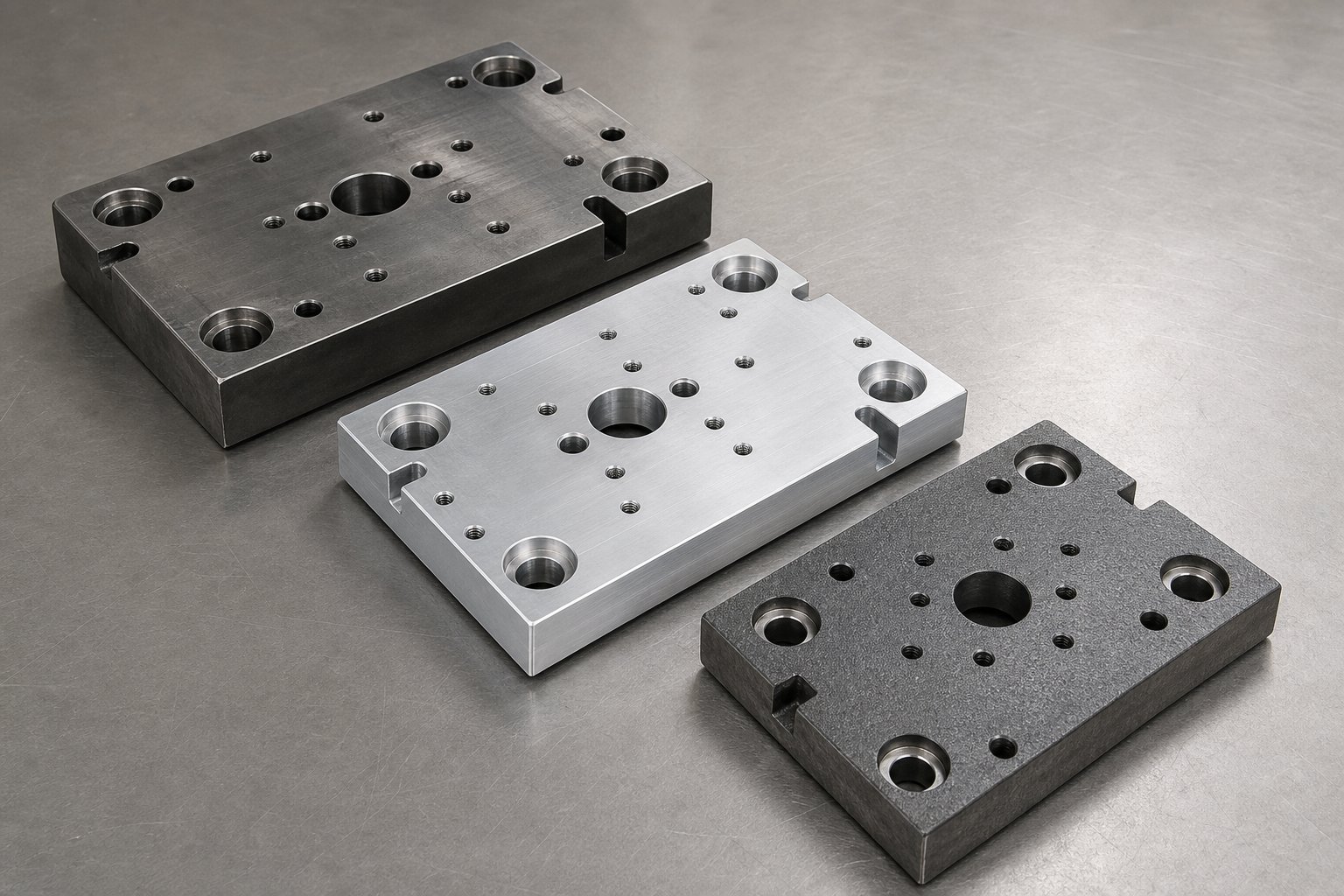
A die set can have perfect guide alignment, ideal post configuration, and the right bearing system - and still underperform because the shoes themselves flex, warp, or weigh too much for the application. Die shoe material is the decision that governs rigidity under load, thermal stability across long runs, handling logistics during die changes, and long-term dimensional retention through millions of press cycles. Yet most specifications default to steel without considering whether it's actually the best fit. Three material families cover the range of stamping applications: steel, aluminum alloy, and cast iron. Each solves a different problem, and each introduces its own constraints.
Steel Die Shoes and Their Strength Advantages
Steel is the default for production metal die sets, and for good reason. When your metal press dies face high tonnage, heavy off-center loads, or long uninterrupted production runs, nothing matches the rigidity and deflection resistance of a properly specified steel shoe. The most common grades break down by application severity.
A36 structural steel is the entry point - affordable, widely available, and easy to machine. It works well for light-to-moderate stamping where absolute deflection control isn't critical. But A36 carries residual stresses from rolling and cutting that can release over time, causing the shoe to distort slightly after machining. For steel stamping dies expected to hold tight parallelism over hundreds of thousands of cycles, stress-relieved A36 or a step up in grade becomes necessary.
4140 alloy steel is the workhorse for demanding applications. After quenching and tempering, it delivers higher yield strength and fatigue resistance than A36, meaning the shoe deflects less under repeated impact loading and retains its flatness longer. Shops running high-tonnage compound or progressive steel dies routinely specify 4140 for both upper and lower shoes when the die will see production volumes exceeding 500,000 hits.
The trade-offs are weight and machining cost. A steel die shoe weighs roughly three times more than an equivalent aluminum shoe. For a large progressive die with shoes measuring 36 by 60 inches, that translates to hundreds of pounds of additional weight that affects crane capacity, press tonnage allocation, and die-change time. Machining steel also takes longer, though modern milling technology can achieve surface accuracy comparable to grinding for die shoe applications.
Aluminum Die Shoes for Weight Reduction
When does a sheet metal die set benefit from aluminum shoes? Not when press tonnage is the constraint - aluminum's lower modulus means more deflection under the same load. But when the die itself is the heavy object being lifted, transported, stored, and clamped into a press, aluminum changes the logistics equation entirely.
Imagine a large progressive die with steel shoes that weighs 4,000 pounds total. Replace those shoes with aluminum alloy and the die drops to roughly 2,800 pounds. That weight savings affects every touchpoint: smaller overhead cranes, faster die changes, reduced wear on press bolsters, and less strain on automation equipment during die transfer. For plants running frequent changeovers or operating presses near their weight limits, aluminum shoes are a practical necessity rather than a luxury.
Two alloys dominate the metal die set market for aluminum shoes. 7075 aluminum is the high-strength option - after aging treatment, its tensile strength approaches that of low-carbon steel while retaining aluminum's one-third density advantage. Dimensional stability is excellent, making 7075 the choice for sheet metal dies requiring tight parallelism retention over time. QC-7 (a proprietary cast aluminum tool plate) offers similar strength with better flatness as-supplied, reducing the machining needed to bring a shoe into tolerance.
6061 aluminum is the cost-effective alternative. It machines faster, resists corrosion without additional treatment, and costs less than 7075. The strength is lower, so 6061 fits light-to-moderate stamping loads where weight reduction matters more than absolute rigidity. Small metal forming dies for electronic components, connector housings, and thin-gauge blanking are typical 6061 applications.
Aluminum also absorbs shock energy well. As The Fabricator notes, aluminum is a good metal for shock absorption, making it a practical choice for blanking dies where snap-through energy needs dissipation rather than transmission into the press frame. Special alloys can be added to give aluminum greater compressive strength than low-carbon steel, expanding its applicability beyond what the raw density comparison suggests.
Cast Iron and Specialty Material Options
Cast iron occupies a niche that neither steel nor aluminum fills well: vibration damping. Every stamping press stroke generates impact energy, and how quickly that energy dissipates determines noise levels, component fatigue rates, and surface finish quality on stamped parts. Cast iron excels here because of its internal microstructure.
Gray cast iron (Meehanite and similar trade grades) contains flake graphite distributed throughout the iron matrix. These graphite flakes act as internal friction surfaces - when vibrational energy passes through the material, dislocation movements along the graphite's basal planes convert mechanical energy into heat. The result is damping capacity roughly four times that of steel, meaning vibrations decay far faster in a cast iron shoe than in an equivalent steel plate.
Ductile iron (nodular cast iron) offers a middle ground. Its spheroidal graphite structure provides about twice the damping capacity of steel while delivering mechanical properties - strength and toughness - much closer to steel than gray iron can achieve. For metal forming dies that produce moderate loads but benefit from reduced vibration, ductile iron shoes represent a cost-effective solution that doesn't sacrifice structural integrity.
The downside? Cast iron is heavier than steel for equivalent rigidity and cannot be easily modified after casting. You won't mill new mounting holes or relocate guide pin bores as readily as you would in a steel or aluminum shoe. Cast iron also fractures rather than deforms under extreme overload, which makes it unsuitable for applications where accidental tonnage spikes are possible. But for medium-volume production in shops where vibration control, noise reduction, and cost containment outweigh absolute rigidity, cast iron shoes remain a legitimate specification.
The comparison below maps each material family against the performance characteristics that drive die shoe selection:
| Property | Steel (A36/4140) | Aluminum (7075/QC-7) | Cast Iron (Gray/Ductile) |
|---|---|---|---|
| Relative Weight | Heavy (baseline) | Light (~1/3 of steel) | Heavy (comparable to steel) |
| Rigidity Under Load | Highest | Moderate (lower elastic modulus) | High (gray) to Very High (ductile) |
| Machinability | Moderate | Excellent (fast cutting speeds) | Good (but difficult to modify post-casting) |
| Relative Cost | Medium | Medium-High (7075) / Medium (6061) | Low to Medium |
| Vibration Damping | Low | Moderate (good shock absorption) | Excellent (gray iron) / Good (ductile iron) |
| Recommended Use Case | High-tonnage production stamping, progressive and compound dies | Large dies with weight constraints, frequent die changes, blanking operations | Medium-volume work, vibration-sensitive operations, noise-critical environments |
No single material wins across all criteria. The decision traces back to your specific constraints: tonnage and deflection limits point toward steel, weight and handling logistics favor aluminum, and vibration or noise concerns justify cast iron. In many shops, different dies within the same press line use different shoe materials based on what each operation demands.
Material selection sets the physical boundaries of what a die set can handle. But the real specification challenge lies in matching all these variables - guide type, post configuration, and shoe material - to the specific stamping operation the die will perform. Progressive, compound, and transfer operations each impose distinct demands that shape every die set decision differently.
Matching Die Sets to Progressive Compound and Transfer Operations
You can specify the right guide system, the right post configuration, and the right shoe material - and still end up with a die set that underperforms. How? By ignoring the stamping operation type that defines how all those variables need to work together. A progressive die and a compound die impose fundamentally different demands on their die sets, even when they're stamping similar materials at similar tonnages. Transfer operations add another layer entirely. The operation type isn't just context for the die set decision - it's the organizing principle that determines which combinations of configuration, guidance, and material actually work.
Die Sets for Progressive Stamping
Progressive dies move a strip of sheet metal through multiple stations in sequence, performing a different operation at each stop - piercing at station one, forming at station three, blanking at station seven. Each station depends on the strip registering in exactly the same lateral and longitudinal position relative to the die set, hit after hit. That registration requirement is what makes progressive stamping the most demanding application for sheet metal stamping dies from a die set perspective.
The geometry of the die set follows the geometry of the process. Progressive dies are long and narrow, often with shoe length-to-width ratios of 3:1 or greater. Strip width determines shoe width, but the number of stations and the pitch between them drives the shoe length. A twelve-station progressive die with 2-inch pitch needs at least 24 inches of working length, plus additional shoe material beyond the first and last stations for guide pin placement and structural support.
Guide spacing matters here more than in any other operation type. With a long, narrow shoe, the guide pins are widely separated in the feed direction but closely spaced across the width. That geometry provides excellent resistance to lateral misalignment (the direction most critical for punch-to-die registration) but less resistance to angular rotation in the feed direction. Ball bearing guide systems are the standard for progressive stamping precisely because the cumulative tolerance stack across multiple stations demands zero-clearance alignment. A plain bearing system with even 0.0004 inches of play translates into measurable positional error at stations far from the guide pins.
Back-post or diagonal-post configurations dominate progressive applications because the strip must enter from one side and exit the other without encountering an obstruction. As Larson Tool explains, progressive dies operate through sequential stations where a strip of metal feeds into the die and moves through various stations, with each performing a specific operation like cutting, bending, or punching. That continuous strip feeding path cannot accommodate guide posts in the feed line.
For punch press dies in progressive applications, the die set also needs to accommodate auxiliary systems: pilot pins that register the strip at each station, sensors that detect misfeeds, and nitrogen springs or urethane strippers that manage strip lift between strokes. All of these mount to the die shoes and occupy vertical real estate within the shut height. Shoe thickness must balance rigidity against the available daylight in the press.
Die Sets for Compound and Blanking Operations
Compound dies take a different approach. Instead of spreading operations across multiple stations, a compound die performs two or more cutting operations in a single stroke - typically blanking and piercing simultaneously. The punches and dies work in both directions: the blanking punch pushes down through the lower die opening while piercing punches mounted in the lower shoe push upward through the workpiece at the same moment. This produces a flat, accurate blanking die part with pierced holes held in precise relationship to the blank edge, all in one press cycle.
The load profile is what distinguishes compound operations from a die set perspective. Because all cutting forces act simultaneously across a relatively compact area, the total tonnage is high but generally well-centered. There's no strip progression creating station-to-station variation, and the forces don't migrate across the die face during the stroke the way forming dies generate traveling loads.
This centered, balanced load profile favors four-post or center-post die set configurations with heavy-section steel shoes. The four-post arrangement resists the high instantaneous deflection that occurs when all punches and dies engage simultaneously. Steel shoes in 4140 or stress-relieved A36 provide the rigidity needed to maintain parallelism under what can be substantial blanking forces - a forming die might require 20 tons distributed across a forming pad, while a compound blanking die of similar size can demand 60 or more tons concentrated in a single stroke.
Guide system requirements for compound operations are less extreme than for progressive work. The press die closes once, performs the operation, and opens - there's no cumulative error from station to station. Plain bearing guides at commercial precision class work well for medium-volume compound stamping, though shops running tight-tolerance blanking (medical components, electronic connectors, precision washers) still benefit from ball bearing systems that eliminate any lateral play during the critical cutting moment.
Compound dies also produce balanced snap-through energy because the cutting perimeters are distributed symmetrically. That makes the die set less susceptible to rocking or tilting during breakthrough, but the total shock energy is high. Shoes with good vibration damping characteristics - cast iron or thick-section steel - help manage that energy without transmitting excessive fatigue loading into the guide assemblies.
Transfer Die Set Considerations
Transfer stamping operates on a fundamentally different principle than either progressive or compound work. Rather than feeding a continuous strip through one die, transfer systems use mechanical fingers or grippers to pick up individual blanks and move them between separate die stations mounted on a common bolster. Each station has its own press die and - critically - its own die set.
This creates a specification challenge that doesn't exist in progressive or compound tooling: inter-die alignment. Each forming die in a transfer line must register its workpiece in the same spatial coordinate system as every other station. If die set number three is shifted 0.002 inches laterally relative to die set number two, the part coming out of station three carries that error forward into every subsequent operation. The punches and dies at downstream stations then work against a part that's already mislocated, compounding dimensional problems with each transfer.
Transfer dies handle large or intricate parts that require multiple operations, where a blank is cut and then transferred through various stations for forming, bending, or other operations. Each station operates independently, which gives designers flexibility to produce complex shapes but demands that every individual die set achieve tight positional accuracy on the bolster.
Die sets for transfer operations typically use four-post configurations because each station may perform heavy forming with significant off-center loads - deep draws, flanging, or trimming operations that generate lateral thrust in unpredictable directions depending on the part geometry at that stage. The four-post arrangement resists these loads without relying on heel blocks alone. Steel shoes are standard because the individual die sets need to maintain dimensional stability under repeated heavy forming loads across long production campaigns.
One consideration unique to transfer work: because each die set is relatively compact (handling one operation on a single part rather than twelve operations on a strip), the sheet metal punch and die combinations at each station can be optimized independently. Station one might use a shallow forming die set with plain bearing guides because the loads are moderate. Station four, performing a deep draw with severe side loading, might require ball bearing guides and maximum shoe thickness. This per-station optimization is a luxury that progressive stamping doesn't allow, where one die set must serve all stations simultaneously.
The following decision sequence connects operation type to die set specification in a logical order:
- Identify the operation type - progressive, compound, or transfer - because it determines the load profile, geometric envelope, and access requirements.
- Determine load magnitude and distribution - centered and balanced (compound), distributed across stations (progressive), or variable by station (transfer).
- Select post configuration - back-post or diagonal for progressive feed clearance, center-post or four-post for compound load distribution, four-post for transfer rigidity.
- Specify the guide system - ball bearing for progressive precision and speed, plain or ball bearing for compound based on volume, per-station selection for transfer based on individual load demands.
- Choose shoe material - steel for high-tonnage compound and transfer stations, aluminum for large progressive dies with weight constraints, cast iron where vibration damping justifies the trade-offs.
This sequence works because each decision constrains the next. You can't intelligently choose a post configuration without knowing whether strip must feed through the die. You can't specify the guide system without knowing whether cumulative station-to-station accuracy matters. And you can't select shoe material without understanding the tonnage, thermal, and handling demands of the specific forming dies involved.
Knowing which die set configuration suits your operation type is the design-side challenge. The procurement-side challenge is equally consequential: translating that knowledge into a specification that a supplier can quote accurately and build correctly. That means defining exact dimensions, tolerances, and production parameters before the first conversation with a die set vendor.
How to Select and Specify the Right Die Set
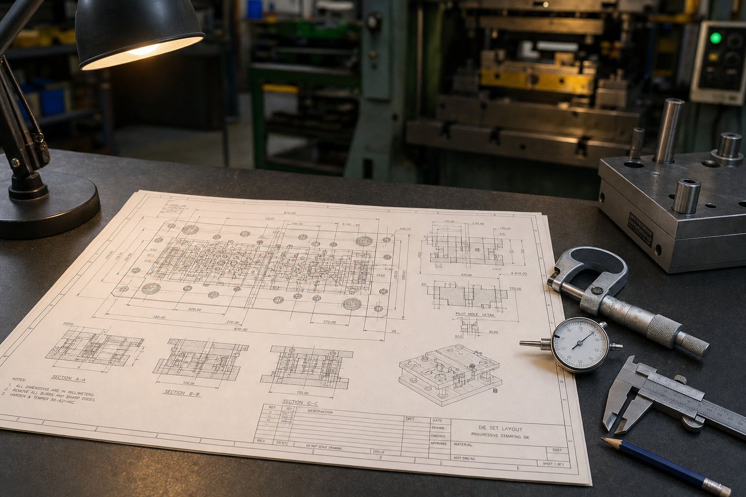
Knowing what a die set should look like for your application is one thing. Communicating that knowledge to a supplier in a way that produces the correct result is something else entirely. The gap between design intent and procurement execution is where most specification errors live. A tooling engineer might understand exactly which post configuration and guide system the operation demands, but if the purchase order lacks the dimensional constraints that tie those choices to the press, the delivered die set may not fit, perform, or last. Bridging that gap requires a disciplined approach to defining dimensions, tolerances, and production parameters before any quote request goes out.
Critical Dimensions and Tolerances to Specify
Every die set specification traces back to two reference points: the press it will run in, and the part it must help produce. Miss either connection and you're buying a die set that works in theory but fails in practice.
Start with shut height. As MetalForming Magazine explains, die shut height refers to the overall height of a die assembly in its fully closed position - and it must fall within the minimum and maximum die-height space of the target press. If the die shut height exceeds the available space, the press frame stretches and connections compress, generating excessive tonnage that damages both die and press. Calculate maximum die height by subtracting bolster thickness from press shut height, then subtract the ram-adjustment length to find minimum die height. Your die set's closed height must land between those two numbers with room for adjustment.
Daylight - the open space between shoes when the die is fully open - determines whether your tooling dies have enough vertical clearance for strip feeding, part ejection, and scrap removal. Shoe thickness directly trades off against daylight within a fixed shut height: thicker shoes provide more rigidity but consume vertical space that the working elements need.
Guide pin diameter, bushing class, and the precision fit between them define alignment capability. Larger pins resist deflection better under heavy loads, but they consume shoe area that might be needed for tooling mounts. Bushing class - commercial, precision, or super-precision - sets the maximum lateral play allowed during operation. And parallelism tolerance between upper and lower shoe mounting faces controls how evenly cutting forces distribute across the die face. The ANSI B94.6 standard specifies die set component tolerances, with parallelism requirements typically at 0.02mm per 300mm of shoe length for precision applications.
Production Volume and Speed Requirements
Your anticipated production volume dictates whether the cost of a ball bearing guide system is justified or whether plain bearings deliver adequate performance at lower investment. This isn't a vague guideline - it's a calculable decision.
For runs under 50,000 hits per year, plain bearing die sets at commercial precision class handle most applications without excessive wear. The bushing replacement interval at moderate stroke rates gives you years of service before maintenance costs accumulate. Between 50,000 and 500,000 annual hits, the calculation shifts: ball bearing guides reduce cumulative maintenance, hold tighter tolerances across longer runs, and keep punch-to-die alignment stable as thermal conditions change through extended production cycles.
Above 500,000 hits per year - especially in high-speed progressive stamping - precision ball bearing systems pay for themselves in reduced scrap, longer punch life, and fewer unplanned stops. The stroke rate relationship is straightforward: higher speeds generate more heat in plain bearing systems, accelerating wear and reducing the effective maintenance window. Ball bearing guides remain thermally stable at 300-plus strokes per minute where plain systems would require mid-run lubrication breaks.
Sounds like a simple volume threshold? It's more nuanced than that. A custom metal stamping die running 100,000 cycles but holding plus-or-minus 0.001-inch tolerances may need ball bearing guidance at volumes that would normally fall in the plain bearing range. Tolerance requirements and volume together determine the right guide system - neither factor alone tells the full story.
Working With a Die Set Supplier
Before engaging stamping die manufacturers, prepare the following information. Walking into a quoting conversation without these details forces the supplier to assume - and assumptions become errors in the finished die set.
- Press model and rated tonnage - confirms that the die set design stays within the press capacity envelope.
- Shut height range - minimum and maximum die height space, accounting for bolster thickness and ram adjustment.
- Bolster dimensions and T-slot pattern - determines shoe footprint limits and clamping method.
- Feed direction and strip/blank handling method - drives post configuration selection (back-post for coil-fed progressive, four-post for transfer).
- Estimated annual volume and target stroke rate - determines guide system class and shoe material grade.
- Required part tolerances - the dimensional accuracy of the stamped part traces back to die set alignment capability.
- Die weight constraints - crane capacity and press weight limits may mandate aluminum shoes over steel.
- Environmental conditions - dirty or high-temperature shops may favor plain bearings over ball bearing systems for contamination resistance.
For standard applications - simple blanking, single-station forming, short-run prototyping - catalog die sets from established die manufacturers get the job done at predictable cost and lead time. You select shoe size, post configuration, guide system, and material from available options, and the set arrives ready to mount tooling.
Where standard options fall short is in complex custom metal stamping dies that require non-standard shoe geometries, unusual guide pin placements, integrated nitrogen manifolds, or die sets engineered around specific forming sequences. These design-heavy decisions push beyond what a catalog can address. Suppliers like YICHEN specialize in custom stamping die solutions where engineers need support on die structure, component specification, punch and lifter integration, clearance optimization, and material flow - making them a strong resource when the application requirements don't fit neatly into standard die manufacturing categories.
The specification process itself is a custom die exercise in communication. Every dimension you define constrains the supplier's design space in a productive way. Every dimension you leave undefined becomes a decision the supplier makes without your context. The more complete your specification, the more likely the delivered die set performs the way your tooling dies need it to from the first hit.
A well-specified, well-built die set is only as good as its ongoing performance in the press. And even the best specifications can't prevent the gradual degradation that every stamping die set experiences over time. Recognizing the symptoms of that degradation early - before it shows up in part quality or catastrophic failure - is the difference between a planned maintenance stop and an emergency that shuts down a production line.
Troubleshooting Common Die Set Problems
A die set doesn't fail all at once. It whispers before it screams. The guide pin that galls on one side, the burr that migrates from station to station, the hole position that drifts half a thousandth per shift - these are not random quality events. They're symptoms with traceable causes, and nearly all of them point back to the die set framework rather than the working tooling mounted to it. Yet most shops treat these symptoms by adjusting stamping die punches, tweaking cutting clearance, or replacing press punch dies - temporary fixes that mask the real problem while it worsens underneath.
Most die set problems originate from specification or setup errors, not from component defects. A correctly specified die set that is improperly installed, inadequately maintained, or operated beyond its design parameters will fail long before its components reach their material fatigue limits.
Diagnosing Misalignment and Galling
Galling on guide pins or bushings is the most visible symptom of misalignment - and the one most often misdiagnosed. You'll notice material transfer marks, scoring, or smeared metal on the pin surface or inside the bushing bore. These marks tell you that two surfaces are making metal-to-metal contact under load, generating enough heat and pressure to micro-weld and tear material from one surface to the other. As JVM Manufacturing explains, even slight misalignments prevent stations from operating smoothly, causing uneven wear and dimensional inconsistencies that create a domino effect throughout the entire die system.
What causes it? Three root conditions, alone or in combination:
- Worn bushings - the running clearance between pin and bushing has opened beyond specification, allowing the upper shoe to shift laterally before the pin centers it. That shift means the pin enters the bushing at a slight angle each stroke, concentrating contact pressure on one side.
- Deflected die shoes - a shoe that has lost flatness from repeated impact loading bows under tonnage, tilting the bushing bore out of parallel with the guide pin axis. The pin and bushing are misaligned only under load, which makes the problem invisible during static inspection.
- Improper press adjustment - if the press ram isn't parallel to the bolster, or if die clamps apply uneven force during mounting, the entire die set operates in a skewed condition that no internal alignment can correct.
Inspection is straightforward if you know what to look for. Pull the die set from the press and examine each guide pin under good lighting. Galling marks appear as shiny, smeared patches - typically on one side of the pin, indicating directional misalignment. Check the corresponding bushing bore for matching marks on the opposite side. If galling is present on both pins in the same rotational position, the problem is likely press-related (ram parallelism or die clamp unevenness). If it appears on only one pin or in different positions, suspect shoe deflection or localized bushing wear.
Corrective actions follow the diagnosis: replace worn bushings and ream the bores if necessary. Re-grind shoe mounting faces to restore parallelism. Re-level the press or adjust die clamps for even pressure distribution. In severe cases where galling has scored the guide pin surface, the pin itself needs replacement - a scored pin will accelerate bushing wear even in a freshly reamed bore.
Premature Wear and Guide Pin Failure
Guide pins shouldn't wear out fast. A properly specified pin in the right application lasts millions of cycles. When die punches and guide pins start showing premature wear - scoring, diameter reduction, or surface pitting well before their expected service life - something in the operating conditions has exceeded the design envelope.
The common root causes:
- Insufficient lubrication - plain bearing guide systems depend on a lubricant film between pin and bushing. When that film breaks down, friction spikes and wear accelerates exponentially. Industry data shows that lubrication isn't a cure-all, but its absence is catastrophic - it cannot restore a dulled edge or realign a guide pin, but without it, sliding surfaces generate the friction and heat that destroy both pin and bushing in short order.
- Excessive off-center loads - when the stamping operation generates lateral thrust that exceeds what the heel blocks can absorb, the remaining force transfers into the guide pins. Pins are designed primarily for alignment, not for load-bearing. Sustained side loading creates bending stress at the pin's press-fit junction with the shoe, eventually fatiguing the pin or wearing an oval into the bushing.
- Incorrect guide pin material grade - a pin hardened to 58 HRC in an application with heavy shock loads will chip or spall at the surface. A pin at 45 HRC in a high-speed application will wear too quickly. Material grade must match both the load type (impact vs. sliding) and the operating speed.
- Running beyond the rated stroke speed for a plain bearing system - every plain bearing has a PV (pressure-velocity) limit. Exceed it and the lubricant film collapses, friction-generated heat builds faster than it dissipates, and the pin-bushing interface transitions from wear to destruction. This is the classic failure mode when a press die punch operation gets moved from a moderate-speed press to a faster one without upgrading the guide system.
When you find premature wear, resist the impulse to simply replace the pin and bushing. If the operating conditions haven't changed, the new components will follow the same failure trajectory. Instead, identify which root cause applies and address it - upgrade the lubrication method, add or resize heel blocks, re-specify the pin material, or upgrade to ball bearing guidance if the application has outgrown what plain bearings can deliver.
Parallelism Loss and Its Effect on Part Quality
Die shoe parallelism degrades over time. Every press stroke delivers impact energy into the shoes, and that repeated loading gradually alters their geometry. The change is measured in thousandths of an inch - invisible to the eye, undetectable by casual handling - but it cascades into part quality problems that seem unrelated to the die set.
When the upper shoe loses parallelism to the lower shoe, the punching die clearance between punch and die button becomes uneven across the die face. One side of a pierced hole sees tighter clearance while the opposite side opens up. Tighter clearance produces clean shear but accelerates punch wear. Looser clearance allows material to tear rather than shear cleanly, producing burrs that grow progressively worse on one side of every cut feature.
The effects compound from there. Uneven clearance means uneven cutting forces, which generates asymmetric snap-through loads that further accelerate parallelism loss - a self-reinforcing degradation cycle. Forming operations suffer differently: a non-parallel die set delivers uneven blank-holder pressure, causing wrinkles on one side of a draw and thinning on the other. Dimensional drift in stamped parts becomes the shop-floor symptom, but the root cause sits in the die shoes, not in the metal punches and die components doing the forming.
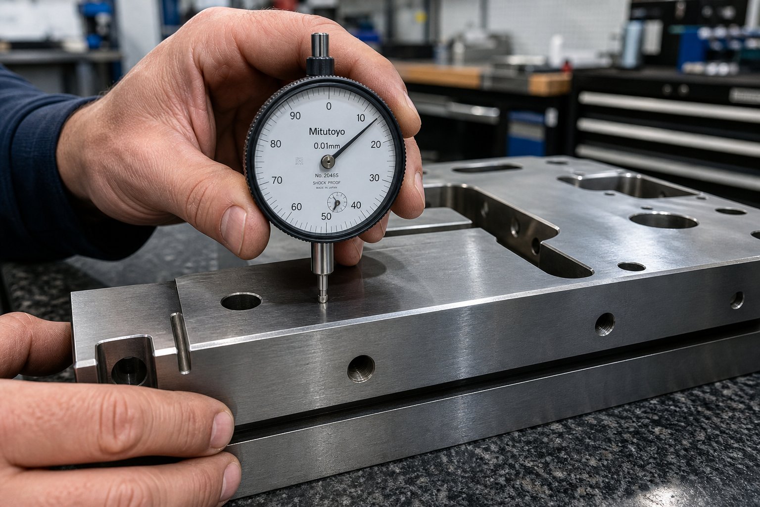
Measuring parallelism requires a surface plate and a dial indicator or height gauge. With the die set closed and no working tooling installed, indicate across the upper shoe's top surface while referencing the lower shoe's bottom surface. Deviation should fall within the original specification - typically 0.0002 to 0.0005 inches per inch of shoe length for precision applications. If it exceeds that range, the shoes need re-grinding to restore flatness and parallel relationship.
Five-Point Die Set Troubleshooting Checklist
When a die set starts producing quality problems, work through these five failure modes systematically. Each connects a visible symptom to its most probable cause and the correct action:
- Symptom: Galling marks on guide pins or bushings. Cause: Worn bushings, shoe deflection, or press misalignment creating angular contact. Action: Replace bushings, re-grind shoes to restore parallelism, verify press ram-to-bolster alignment, and check that die clamps apply even clamping force.
- Symptom: Premature guide pin diameter reduction or surface scoring. Cause: Insufficient lubrication, excessive side loading beyond heel block capacity, or operating above the PV limit of the plain bearing system. Action: Upgrade lubrication method or interval, resize heel blocks to absorb lateral forces, or upgrade to ball bearing guides if speed demands exceed plain bearing capability.
- Symptom: Burrs consistently heavier on one side of pierced or blanked features. Cause: Parallelism loss between upper and lower shoes creating uneven cutting clearance across the die face. Action: Measure shoe parallelism with a dial indicator on a surface plate; re-grind shoes if deviation exceeds specification.
- Symptom: Progressive dimensional drift in hole position or trim location across a production run. Cause: Thermal expansion in the guide system (plain bearings running hot at high speed) or gradual bushing wear opening the clearance envelope. Action: Monitor guide system temperature during production; reduce stroke rate or switch to ball bearing guides for thermal stability. Replace bushings if clearance exceeds specification.
- Symptom: Sudden increase in press tonnage required with no material change. Cause: Die set binding from contamination in guide system, a press die punch stack-up from slug accumulation, or a guide pin that has shifted in its press-fit bore. Action: Clean and inspect guide assemblies, clear slug paths, verify pin press-fit retention, and check for foreign material between shoe and bolster.
Notice the pattern: every failure on this list traces back to either a specification error (wrong guide system for the speed, undersized heel blocks for the load) or a setup and maintenance gap (inadequate lubrication, skipped parallelism checks, uneven clamping). Component defects - a guide pin with an internal flaw or a bushing with an out-of-spec bore - are rare by comparison. If your shop is experiencing recurring die set problems, the troubleshooting path almost always leads to how the set was specified, installed, or maintained rather than to a bad batch of pins.
Identifying the failure mode tells you what's wrong today. Preventing recurrence requires a maintenance and inspection discipline that catches degradation before it reaches the threshold where parts go bad. That discipline - what to check, how often, and when to refurbish versus replace - is what separates shops that react to die set failures from shops that rarely experience them.
Maintenance and Lifecycle Practices That Protect Your Investment
Troubleshooting tells you what went wrong. Maintenance keeps it from going wrong in the first place. Yet most die shops treat die set care as reactive - they replace a bushing when galling appears, re-grind a shoe after parts go out of tolerance, or order new guide pins when the old ones score beyond use. That reactive cycle costs more in downtime, scrap, and emergency procurement than a structured preventive program ever would. The difference between a die set that lasts five years and one that delivers fifteen years of reliable service almost always comes down to what happens between production runs, not during them.
Routine Inspection Schedule for Die Sets
A practical inspection cadence doesn't require shutting down production for days. It requires knowing what to check, how often, and what the measurements mean. Here's the framework that keeps die equipment performing within specification:
Every production run (before and after): Inspect guide pins and bushings visually for galling marks, scoring, or discoloration. Check that ball bearing cages return to their proper rest position (for ball bearing systems). Wipe pins clean and look for metal transfer or embedded debris. Run a finger along the pin surface - any roughness you can feel is roughness that's accelerating bushing wear.
Quarterly: Measure die shoe parallelism using a dial indicator referenced from a surface plate. Compare readings to baseline measurements recorded when the die set was new or last refurbished. Acceptable drift depends on the precision class, but as a general guideline, deviation beyond 0.0005 inches per foot of shoe length warrants attention. Check guide pin diameters at multiple points along the working length using a micrometer - taper or ovality indicates uneven loading or misalignment that the visual inspection may not catch.
Annually (or every 500,000 strokes, whichever comes first): Perform a full dimensional inspection of the die assembly. Measure bushing bore diameters and compare to the guide pin OD to calculate actual running clearance. For ball bearing systems, check preload by feel - any perceptible looseness indicates worn bearings or cage damage. Inspect shoe mounting faces for surface damage, fretting corrosion at bolt locations, or localized depressions where tooling has been repeatedly clamped. This annual check is the equivalent of what any experienced die maker tools through on a rebuild - except you're catching problems before they require one.
Lubrication and Storage Best Practices
Lubrication requirements differ sharply between guide system types, and using the wrong lubricant is nearly as bad as using none at all.
For plain bearing systems, apply a quality way oil or machine oil to guide pins before every production run. The lubricant film must be present before the first stroke - running dry even briefly accelerates wear disproportionately. Re-lubricate during extended runs at intervals appropriate to the stroke rate; high-speed operations may need mid-shift application. Avoid over-lubrication that drips onto the strip material or work surfaces, which contaminates parts and can cause forming defects.
For ball bearing guide systems, grease is not recommended. Because ball bearing components work in negative-clearance preloaded conditions, grease tends to hold contaminants that work into the rolling press fit, generating heat and flat spots on the bearings. Instead, use a refined mineral oil with a viscosity of approximately 290/340 SSU at 100 degrees F, containing extreme-pressure additives and rust inhibitors. Lube pins - guide posts with internal cross-drilled lubrication holes - can connect to automatic systems that deliver oil at specified intervals without manual intervention.
Storage practices matter as much as lubrication during production. When a die set goes into storage between production campaigns, three conditions destroy it silently: rust, warpage, and contamination.
- Rust prevention: Coat all exposed steel surfaces - guide pins, bushing bores, shoe faces - with a rust-preventive oil or vapor corrosion inhibitor (VCI) wrap. Humidity in an uncontrolled die shop environment attacks unprotected hardened steel surfaces within days.
- Warpage prevention: Store die sets on proper die storage bases that support the lower shoe across its full footprint. A shoe stored on two narrow rails with unsupported span in between will sag under its own weight over time - particularly aluminum shoes, which creep more readily than steel. Never stack heavy objects on top of stored die sets.
- Contamination control: Cover stored die sets to prevent grit, metal fines, and airborne debris from settling into guide assemblies and bushing bores. A stock die pulled from storage and run without cleaning first introduces abrasive particles directly into the bearing path on the very first stroke.
When to Refurbish or Replace a Die Set
Every die set reaches a point where maintenance alone can't restore performance. The question is whether that threshold calls for refurbishment or full replacement - and making the wrong call in either direction costs money. Replace too early and you've abandoned serviceable die equipment. Refurbish too late and you're investing repair dollars in a set that will fail again shortly.
The decision framework is condition-based, not age-based:
Refurbish when:
- Bushing replacement restores guide clearance to specification.
- Shoe parallelism can be corrected by surface grinding without reducing shoe thickness below the minimum required for rigidity.
- Guide pin surfaces are scored but pin diameters remain within tolerance after polishing.
- Heel block wear plates can be shimmed or replaced without affecting overall die machining integrity.
Replace when:
- Shoe parallelism is beyond grinding tolerance - meaning the material removal needed to restore flatness would reduce the shoe below its structural minimum thickness.
- Guide pin mounting holes have elongated, meaning the pin's press-fit retention is compromised and the pin can shift under load regardless of bushing condition.
- Multiple previous refurbishments have consumed the available grinding stock, leaving shoes too thin to resist deflection under full press tonnage.
- The die set's original specification no longer matches current production requirements - changed tolerances, higher volumes, or new press equipment that demands different shut heights or guide configurations.
That last point deserves emphasis. When an aging die set needs to be re-engineered rather than simply duplicated - because production requirements have evolved, tolerances have tightened, or the original design had inherent limitations - a catalog replacement of the same stock die configuration may perpetuate the original problems. For engineers evaluating these situations, suppliers like YICHEN support tooling engineers with custom stamping die solutions covering die structure, component design, burr control, and clearance optimization. This kind of engineering support becomes particularly valuable when the replacement decision is also an opportunity to eliminate chronic issues that machining dies back to original spec would simply carry forward.
The following step-by-step routine consolidates maintenance into a repeatable process that any die shop can implement without specialized equipment beyond what's already on the floor:
- Clean all guide surfaces - wipe guide pins, bushings, and heel block faces free of lubricant residue, metal fines, and debris after every production run.
- Inspect visually for damage - check for galling marks, scoring, discoloration, or cage creep indicators on ball bearing systems.
- Measure critical clearances - check guide pin-to-bushing clearance at quarterly intervals using calibrated micrometers or bore gauges.
- Verify shoe parallelism - indicate across both shoes on a surface plate quarterly, comparing to baseline measurements and documenting any drift.
- Lubricate per system type - apply appropriate oil to plain bearing pins before each run; apply refined mineral oil (not grease) to ball bearing assemblies at manufacturer-specified intervals.
- Inspect mounting integrity - check that guide pins remain secure in their press-fit bores, that mounting bolts are torqued to specification, and that no fretting corrosion has developed at shoe-to-bolster interfaces.
- Document and trend - record all measurements in a die assembly history log. Trending data reveals degradation rates that predict when refurbishment or replacement will be needed, allowing planned procurement rather than emergency orders.
Proactive maintenance is not about perfection. It's about catching the 0.0003-inch change this quarter before it becomes the 0.002-inch problem next quarter that scraps parts and stops the press. The investment in inspection time is trivial compared to a single emergency die set replacement - and the production confidence that comes from knowing your die sets are within specification, run after run, is what separates shops that manage their tooling from shops managed by their tooling failures.
Frequently Asked Questions About Metal Stamping Die Sets
1. What is the difference between a die set and a complete stamping die?
A die set is the reusable subassembly consisting of upper and lower die shoes, guide pins, and bushings that provides alignment and mounting for all working elements. The complete stamping die includes everything mounted to that framework - punches, die buttons, strippers, springs, and pilots. Think of the die set as the chassis: it doesn't perform cutting or forming directly, but every working component depends on it for precise positioning. When sourcing custom stamping die solutions, suppliers like YICHEN (yichen-group.com/stamping-die/) engineer the complete die structure including the die set framework, punch integration, and clearance optimization as an integrated system.
2. How do I choose between plain bearing and ball bearing guide systems for my die set?
The decision depends primarily on production volume, stroke speed, and tolerance requirements. Plain bearing systems cost less and tolerate contamination and side loads better, making them ideal for short runs, prototyping, and dirty shop environments at speeds below 150 SPM. Ball bearing systems eliminate running clearance through preload, delivering superior repeatability at 300+ SPM for high-volume progressive stamping with tight tolerances. If your annual volume exceeds 500,000 hits or your part tolerances are tighter than plus-or-minus 0.002 inches, ball bearing guidance typically pays for itself through reduced scrap and longer punch life.
3. What causes galling on die set guide pins and how do I fix it?
Galling appears as shiny, smeared metal transfer marks on guide pin surfaces, caused by metal-to-metal contact under load. Three root conditions create it: worn bushings allowing angular entry of the pin, deflected die shoes tilting the bushing bore out of parallel, or improper press adjustment creating a skewed operating condition. To fix it, replace worn bushings and ream bores if needed, re-grind shoe faces to restore parallelism, and verify press ram-to-bolster alignment. If galling has scored the pin surface, replace the pin entirely since a scored surface accelerates new bushing wear immediately.
4. Which die set post configuration should I use for progressive stamping?
Back-post or diagonal-post configurations are standard for progressive stamping. Back-post sets place both guide pins at the rear, leaving the front and sides completely unobstructed for strip feeding from one side to the other. Diagonal-post sets offer improved rigidity over back-post while maintaining reasonable feed clearance along one edge. Four-post configurations, while providing maximum alignment accuracy, obstruct strip feeding paths and are better suited for compound or transfer dies where continuous strip access is not required.
5. How often should die sets be inspected and what measurements matter most?
Inspect guide pins and bushings visually for galling or scoring before and after every production run. Measure die shoe parallelism quarterly using a dial indicator on a surface plate, comparing to baseline values - deviation beyond 0.0005 inches per foot of shoe length warrants corrective action. Perform full dimensional inspection annually or every 500,000 strokes, checking bushing bore diameters against pin OD to calculate actual running clearance. For ball bearing systems, check preload by feel for any perceptible looseness. Document all measurements to trend degradation rates and predict maintenance timing before failures affect part quality.


