


What Is a Progressive Die and Why OEM Factories Rely on It
Imagine a single tool that punches, bends, forms, and trims a metal part in rapid succession, all without human hands touching the workpiece between steps. That tool is a progressive die, and it sits at the heart of every high-volume OEM progressive die & stamping factory you will encounter when sourcing precision metal components.
What Is a Progressive Die
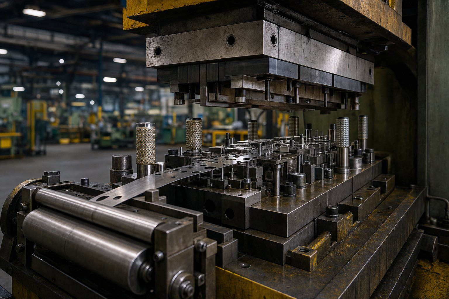
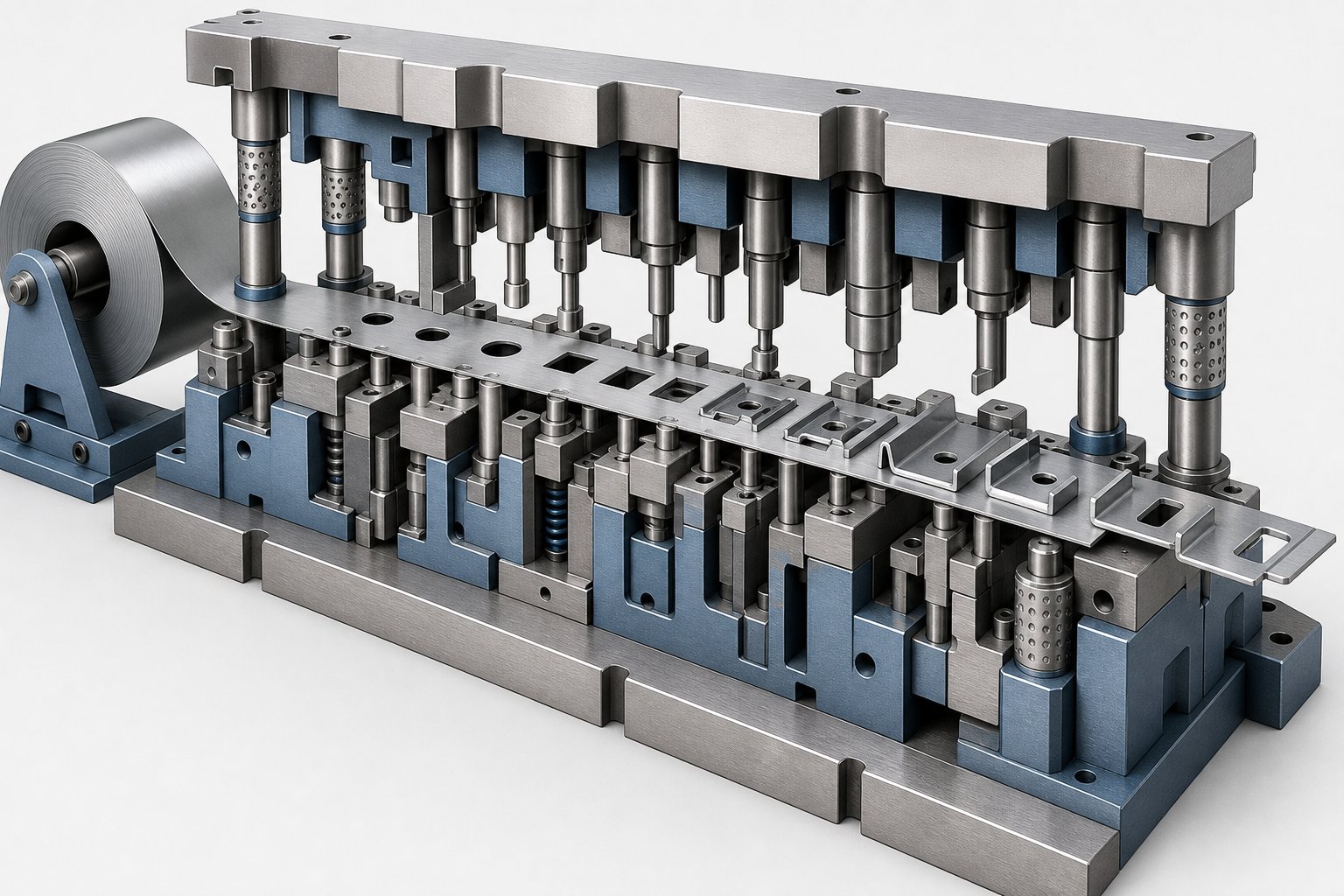
A progressive die is a specialized stamping tool containing multiple stations arranged in sequence inside a single die set. A coil-fed metal strip advances through these stations with each press stroke, and every station performs a distinct operation, such as piercing, blanking, bending, forming, or coining, until the finished part is separated at the final station.
The key concept behind progressive die stamping is simultaneous, sequential action. While one section of the strip is being pierced at station one, another section is being bent at station three, and yet another is reaching cutoff at the final station. Every stroke of the press produces a completed part once the strip has advanced through all stations. This continuous cycle is what makes the prog die so efficient for large production runs.
Contrast this with a single-stage die, which performs only one operation per press stroke at a single station. A part requiring five features, say two holes, a bend, a form, and a trim, would need five separate dies, five press setups, and manual handling between each step. Progressive die stamping consolidates all of those operations into one tool and one press cycle, eliminating part handling, reducing cycle time, and dramatically improving dimensional consistency from piece to piece.
A few terms you will encounter repeatedly when working with stamping factories:
- Stations - Individual positions within the die where a specific cutting or forming operation takes place.
- Strip - The continuous band of sheet metal, unwound from a coil, that feeds through the die.
- Pilot holes - Precision holes pierced early in the strip that locate the material accurately at each subsequent station via pilot pins.
- Carrier strip - The portion of material that connects partially formed parts and transports them through the die until final cutoff.
How OEM Factories Use Progressive Dies
When a brand owner or product company needs thousands or millions of stamped metal components, they rarely build and operate the tooling themselves. Instead, they partner with an OEM progressive die & stamping factory that handles both die engineering and volume production on their behalf.
In this relationship, the OEM buyer, typically a production engineer or procurement team, provides part drawings, volume requirements, and application context. The stamping factory then designs the progressive die, builds the tooling, validates first articles, and runs ongoing production. The factory owns the process expertise; the buyer owns the product design and performance specifications.
This division of labor exists because progressive die design and operation demand deep specialization. Strip layout optimization, station sequencing, force balancing, and pilot registration all require tooling engineers with years of hands-on experience. For the buying organization, outsourcing to a dedicated stamping factory means access to that expertise without maintaining an in-house tool room, press fleet, or die maintenance team.
The payoff is straightforward: high repeatability, low per-piece cost at volume, and consistent quality across production runs that can span millions of strokes. But capturing those benefits depends entirely on what happens inside the die and inside the factory, which is exactly where most buyers lack visibility.
How the Progressive Die Stamping Process Works
What actually happens in those few hundred milliseconds between one press stroke and the next? The progressive die stamping process is deceptively simple in concept but deeply precise in execution. Every cycle transforms raw coil stock into a finished component through a tightly choreographed sequence of mechanical events.
Step-by-Step Station Sequence
Picture a coil of flat metal strip loaded onto an uncoiler, straightened through a leveler, and fed into the die opening. From that point forward, the progressive stamping process unfolds in a fixed order with each press stroke:
- Coil feeding and straightening - The strip unwinds from the coil, passes through a straightener to remove curvature, and a servo or mechanical feeder advances it a precise distance (the feed pitch) into the die.
- Pilot registration - Pilot pins descend into previously pierced holes to lock the strip in exact position before any cutting or forming begins. This eliminates cumulative feed error.
- Piercing and blanking - Punches cut holes, slots, or profile sections. These early stations often establish datum features that later operations reference.
- Forming and bending - Stations progressively shape the flat blank into three-dimensional geometry through bends, draws, or embosses.
- Coining and restrike - Where tight tolerances or specific surface finishes are required, coining stations compress the material to final dimensions.
- Trimming and cutoff - The finished part is separated from the carrier strip and ejected from the die, while scrap webbing is directed into chutes below the press.
Every one of these operations executes simultaneously at different points along the strip during a single press stroke. That overlap is the core reason progressive die stamping achieves throughput rates that single-operation methods cannot match.
Strip layout optimization plays a critical role here. Engineers determine how parts nest on the strip, how wide the carrier tabs need to be, and how much material sits between features. A well-designed layout can push material utilization above 80%, while a poorly planned one generates excessive scrap and drives up piece cost, something OEM buyers rarely see until they examine the strip design in detail.
Press Mechanics and Cycle Speed
The progressive die press that drives this process is sized to match the die's demands. OEM buyers should understand a few core specifications:
- Tonnage - The total force available per stroke, typically ranging from 30 tons for small connector dies up to 600 tons or more for structural automotive parts. Tonnage must exceed the sum of all station forces plus a safety margin.
- Strokes per minute (SPM) - Defines cycle speed. Standard production often runs between 60 and 150 SPM, but high speed progressive die stamping on smaller parts can exceed 300 to 500 strokes per minute, particularly for electrical terminals and thin-gauge components.
- Bed size and strip width capacity - The press bed must accommodate the full die length, which grows as station count increases.
Here is the relationship to keep in mind: more complex part geometry requires more stations, which means a longer die, which demands a larger press bed. A 6-station die for a simple bracket fits a compact press, while a 20-station die for a multi-bend connector assembly may require a wide-bed die stamping press with servo feed capability.
Higher station counts also distribute forming forces more evenly across the strip, reducing stress on any single station and extending die life. But they increase tooling cost and lengthen the die build. For OEM buyers, this tradeoff between part complexity, press requirements, and tooling investment is one of the earliest engineering decisions that shapes project economics, a topic that runs directly into how material choice further influences both die design and production outcomes.
Material Selection Guide for Progressive Die Stamping
The metal you choose does not just define part performance. It shapes die wear rates, lubrication strategies, press speed limits, and ultimately per-piece cost. Yet most OEM buyers specify a material based on end-use requirements alone, without considering how that alloy behaves as it flows through a multi-station progressive die. The engineering rationale behind progressive stamping materials deserves closer attention because it directly affects tooling longevity and production efficiency.
Two broad categories dominate: ferrous metals (carbon steels and stainless steels) and non-ferrous metals (copper, brass, and aluminum alloys). Each carries distinct forming characteristics that influence how a stamping factory designs and maintains the die.
Ferrous Materials for Progressive Stamping
Carbon steel remains the workhorse of steel progressive stamping. Its availability, cost efficiency, and wide range of mechanical properties make it the default starting point for structural brackets, clips, and chassis components. The key variable is carbon content:
- Low-carbon steel (1008, 1010) - Highly ductile and easy to form. Ideal for deep draws, complex bends, and parts requiring significant material flow. Carbon steel progressive stamping with these grades runs at higher press speeds because the soft material generates less punch wear.
- Medium-carbon steel (1045, 1050) - Greater tensile strength and hardness, suited for load-bearing brackets and functional hardware. Reduced ductility means tighter bend radii and more attention to springback compensation in die design.
- High-carbon steel (1070, 1095) - Used for springs, clips, and cutting edges. Formability is limited, so station sequencing must distribute strain carefully to prevent cracking.
Stainless steel progressive stamping introduces higher forming forces and greater die wear compared to carbon steel. The 300 series (304, 316) offers excellent corrosion resistance and is non-magnetic, making it a go-to choice for medical devices, food processing equipment, and marine components. The 400 series (410, 430) provides magnetic properties and moderate corrosion resistance at lower cost, fitting appliance panels and automotive trim applications. Both series work-harden rapidly during forming, which means dies running stainless require harder tool steels or carbide inserts at high-wear stations and more aggressive lubrication to prevent galling.
Typical gauge ranges for ferrous progressive stamping fall between 0.15 mm and 6.0 mm, though most high-speed production concentrates in the 0.3 mm to 3.0 mm range where press speeds and die life remain favorable.
Non-Ferrous Materials and Their Applications
When electrical conductivity, thermal performance, or weight reduction drive the design, non-ferrous alloys step in. Each brings specific forming behaviors that affect die engineering:
- Copper (C110, C101) - Extremely high electrical and thermal conductivity. Copper progressive stamping produces terminals, bus bars, and battery connectors. The softness of pure copper means low punch wear but a tendency for material to adhere to die surfaces (pickup), requiring specialized coatings or lubrication.
- Brass (C260, C280, C360) - A copper-zinc alloy offering a balance of strength, corrosion resistance, and visual appeal. Brass progressive stamping serves electrical contacts, decorative hardware, and plumbing fittings. Good formability and lower springback than steel make it forgiving in multi-bend dies.
- Aluminum (3003, 5052, 6061) - Lightweight with good corrosion resistance. Aluminum progressive stamping is common in automotive heat shields, HVAC fin stock, and consumer electronics enclosures. Aluminum's softness enables high-speed production, but its tendency to gall against tool steel demands careful die surface treatment and consistent lubrication.
The table below consolidates the engineering considerations that OEM buyers and production engineers should weigh when selecting progressive stamping materials:
| Material | Typical Thickness Range | Common Applications | Key Forming Considerations |
|---|---|---|---|
| Low-carbon steel (1008-1010) | 0.3 - 4.0 mm | Automotive brackets, structural clips, enclosures | Excellent ductility; low die wear; minimal springback |
| Medium-carbon steel (1045-1050) | 0.5 - 5.0 mm | Load-bearing brackets, gears, hardware | Higher forming forces; springback compensation needed |
| Stainless steel 300 series | 0.15 - 3.0 mm | Medical devices, food equipment, marine parts | Work-hardens rapidly; requires carbide tooling and heavy lubrication |
| Stainless steel 400 series | 0.3 - 3.0 mm | Appliance panels, automotive trim, magnetic components | Moderate work-hardening; lower cost than 300 series |
| Copper (C110, C101) | 0.1 - 2.0 mm | Electrical terminals, bus bars, battery connectors | Soft; prone to material pickup on tooling; excellent conductivity |
| Brass (C260, C360) | 0.15 - 3.0 mm | Electrical contacts, decorative hardware, plumbing fittings | Low springback; good formability; moderate die wear |
| Aluminum (3003, 5052, 6061) | 0.2 - 4.0 mm | Heat shields, HVAC components, electronics housings | Lightweight; galling risk requires coated tooling; high press speeds achievable |
Notice a pattern: softer, more ductile materials enable faster cycle speeds and longer intervals between die maintenance, while harder alloys demand more robust tooling and tighter process controls. This tradeoff is exactly what shapes the die design engineering phase, where station sequencing, insert material selection, and force calculations translate a material choice into a functioning production tool.
Die Design Engineering and Tooling Economics
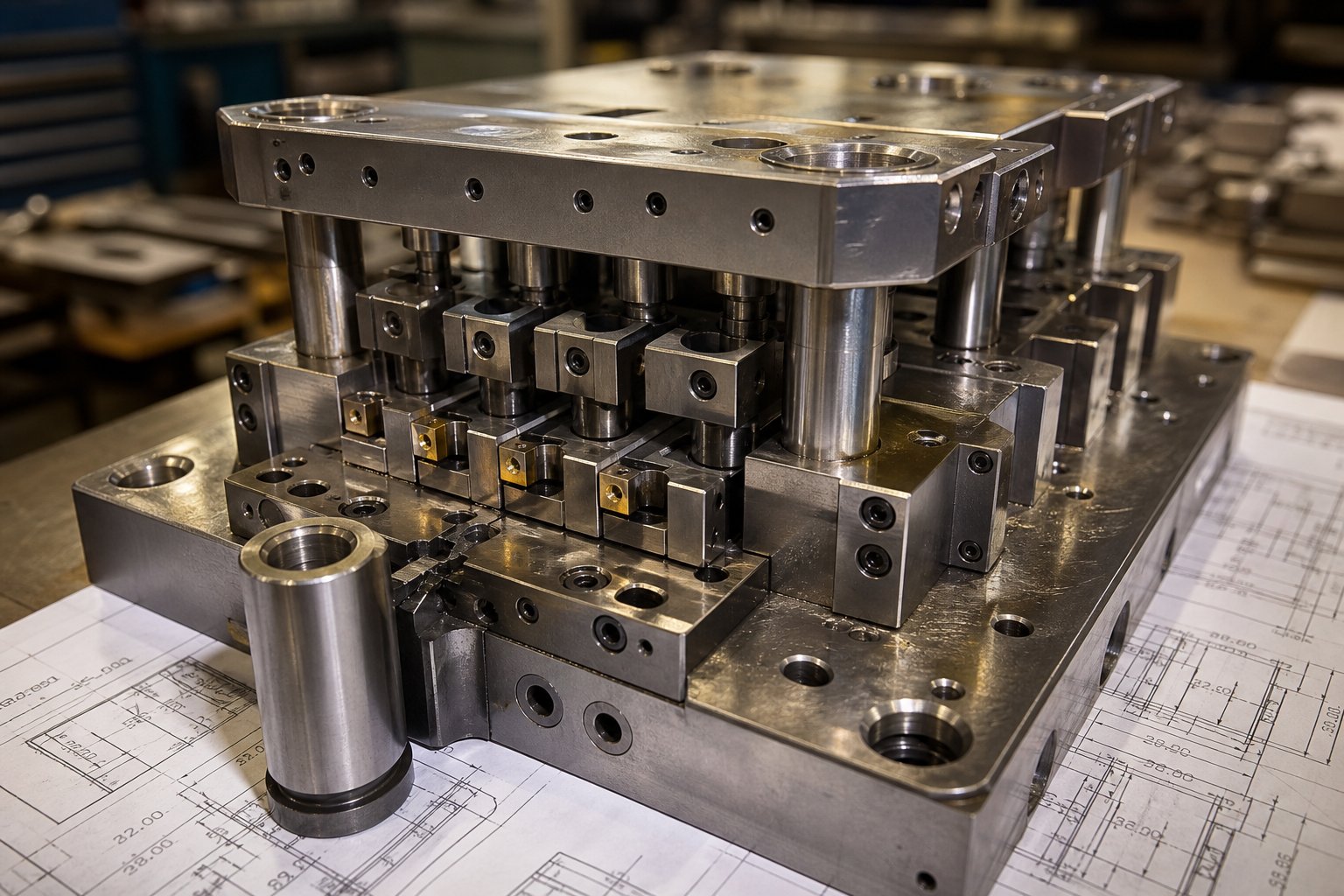
A progressive stamping die design project either succeeds or fails long before the first production stroke. The engineering workflow that transforms a part drawing into a functioning multi-station tool involves close collaboration between the OEM buyer's engineering team and the stamping factory's die designers, and it is where most of the project's cost structure gets locked in.
This collaboration typically starts with a Design for Manufacturability review. The factory's tooling engineers examine the part geometry, identify features that may cause strip instability, suggest modifications that simplify the die without compromising function, and flag tolerance callouts that will drive tooling complexity. DFM changes made at this stage cost nothing. The same changes requested after progressive die tooling is already built become expensive rework.
Strip Layout and Station Planning
Strip layout is where progressive stamping die design becomes both art and engineering discipline. The tooling engineer must answer a series of interdependent questions: How should operations be sequenced across stations? Where does the carrier strip need reinforcement to support partially formed features? How wide must the carrier tabs be to maintain strip rigidity without wasting material?
Several factors drive these decisions:
- Force balancing - Cutting and forming forces at each station must be distributed so the press load remains centered. Unbalanced forces cause uneven die wear and strip deflection.
- Material flow management - Forming stations must account for how metal stretches and thins. Station sequence affects whether a bend or draw will distort features created at earlier stations.
- Scrap optimization - Carrier strip width, pitch distance, and part orientation on the strip all determine material utilization. A well-planned layout can reduce scrap by several percentage points compared to a naive arrangement.
- Station count - More complex part geometry requires more stations. Each additional station adds die length, increases tooling cost, and demands a larger press bed, but it also distributes strain more gradually and improves part quality.
A part may look straightforward on the drawing yet require twelve or more stations once the engineers account for pilot holes, idle stations for strip stabilization, and progressive forming sequences that prevent material cracking. Strip layout is consistently one of the biggest cost drivers in any progressive die program because it dictates nearly everything downstream.
Tooling Lead Times and Cost Factors
Progressive die tooling represents a significant upfront investment, but the economics shift dramatically at volume. Think of it this way: a die that costs tens of thousands of dollars adds meaningful cost per part at 5,000 pieces, but at 500,000 pieces, that same investment contributes fractions of a cent to each unit. Industry data shows progressive dies can range from roughly $10,000 for simpler tools to $350,000 for complex multi-station builds, with well-maintained tooling lasting millions of press cycles.
Several factors push progressive stamping dies toward the higher end of that range:
- Higher station counts for complex geometries
- Tighter tolerances requiring precision ground components and in-process adjustment features
- Harder strip materials that accelerate wear on cutting and forming surfaces
- Requirements for in-die sensing, automatic scrap detection, or part ejection systems
Tooling ownership is another consideration OEM buyers often overlook. Some factories retain die ownership and amortize cost into piece price, while others build tools that the buyer owns outright. Each model has implications for long-term flexibility, especially if you anticipate moving production between suppliers.
The choice of insert materials at high-wear stations directly shapes die longevity. Conventional tool steel (D2, A2, M2) works well for moderate production volumes and softer strip materials. But for progressive carbide stamping dies, tungsten carbide inserts at punch tips and forming surfaces can extend service life by several multiples compared to tool steel, particularly when stamping abrasive stainless alloys or running at high speeds. The tradeoff is cost and brittleness: carbide inserts are more expensive and less forgiving of lateral forces, so they demand tighter press alignment and more rigid die construction.
Lead times for progressive die tooling vary widely based on complexity, factory backlog, and whether prototype tryouts are included. Simpler dies may ship in weeks, while complex multi-station tools with extensive tryout and validation can stretch across several months. OEM buyers who engage factories early in the design phase and complete DFM collaboration before committing to final tooling specs tend to compress timelines and avoid costly mid-build revisions.
All of this engineering effort and tooling investment serves a single purpose: producing parts at the lowest possible total cost once volume ramps. But the decision to invest in progressive tooling only makes sense relative to alternative stamping methods, and understanding where the breakeven sits requires a clear-eyed comparison across processes.
Progressive Die Stamping vs Other Methods
So you know progressive dies deliver low per-piece cost at volume. But is a progressive die and stamping approach actually the right fit for your part? That depends on geometry, run size, material thickness, and how much you are willing to invest in tooling upfront. Four primary stamping methods compete for OEM project dollars: progressive die, transfer die, compound die, and fourslide (multislide). Each occupies a distinct sweet spot, and choosing the wrong one means paying either too much per piece or too much in tooling that never earns back its investment.
Progressive Die vs Transfer Die vs Compound Die
The differences between these processes come down to how the workpiece moves, what part geometries each method handles well, and where the economics favor one over another. Transfer dies, for instance, separate the blank from the strip early and use mechanical fingers to shuttle it between independent stations. This makes them ideal for larger parts requiring deeper draws and more intricate shapes that cannot stay connected to a carrier strip. Compound dies take a different approach entirely: they perform all cutting and forming operations in a single press stroke on a single plane, which makes them fast and inexpensive for simple flat geometries but unsuitable for anything requiring multiple bends or three-dimensional forming.
Fourslide stamping adds another option. Instead of vertical press force, it uses four horizontal tool slides to shape material from multiple angles. This method excels at small, intricately bent components like spring clips, connector contacts, and wire forms where multi-directional bending would be difficult to achieve in a conventional progressive metal stamping setup.
The table below breaks down how these dies and stamping methods compare across the criteria that matter most to OEM decision-makers:
| Criteria | Progressive Die | Transfer Die | Compound Die | Fourslide / Multislide |
|---|---|---|---|---|
| Part complexity | Moderate to high (multi-feature, multi-bend) | High (deep draws, large 3D shapes) | Low (flat, single-plane operations) | Moderate to high (complex multi-angle bends) |
| Ideal volume range | High volume (hundreds of thousands to millions) | Medium to high volume | Low to medium volume | Low to medium volume |
| Material thickness range | 0.1 - 6.0 mm typical | 0.5 - 10+ mm | 0.2 - 6.0 mm | 0.1 - 2.5 mm |
| Tolerance capability | Tight (consistent station-to-station registration) | Tight (independent station alignment) | Good for single-plane features | Moderate (multi-axis variability) |
| Per-piece cost at volume | Lowest at high volumes | Moderate | Low for simple parts | Moderate |
| Tooling investment | High | High (plus transfer mechanism) | Low to moderate | Moderate |
| Ideal applications | Connectors, brackets, terminals, motor laminations | Large body panels, deep-drawn housings, structural parts | Washers, simple blanks, flat shims | Spring clips, wire forms, small bent contacts |
When Progressive Die Stamping Is the Right Choice
Progressive dies earn their investment when several conditions align. You need them when your part requires multiple operations, such as piercing, forming, and trimming, performed in tight sequence at tolerances that demand repeatable station-to-station registration. You need them when annual volumes justify the higher tooling cost through dramatically lower piece prices. And you need them when cycle time matters, because long run progressive stamping on a well-designed die produces parts faster than any transfer or compound alternative at comparable complexity.
The volume threshold where progressive tooling pays off varies by part complexity and material. A general industry principle applies: the more operations your part requires, the lower the breakeven volume becomes relative to performing those operations in separate setups. A simple bracket needing only two features may not justify a progressive die until volumes reach hundreds of thousands. A multi-bend connector with eight features may hit breakeven much sooner because the alternative, running eight single-operation setups with part handling between each, carries high labor and quality risk at any volume.
When should you look elsewhere?
- Transfer dies are preferable when parts are physically too large to remain on a carrier strip, require very deep draws (depth exceeding material width), or need operations on surfaces that are not accessible while the part is connected to webbing.
- Compound dies suffice when the part is flat, geometry is simple, and tolerances are achievable in a single stroke. Washers, shims, and first-operation blanks fall here.
- Fourslide stamping wins when parts are small, require multi-directional bends, and volumes sit in the low-to-medium range where progressive die tooling cannot recover its cost.
For OEM buyers, the decision often comes down to a straightforward question: does the per-piece savings of long run progressive stamping offset the upfront die investment within your projected volume lifecycle? If the answer is yes, and your part needs more than two forming operations, progressive dies almost always deliver the best total cost of ownership.
Selecting the right method, however, is only half the equation. Even the most appropriate process choice loses its value without rigorous quality control to ensure that every part leaving the die meets specification, stroke after stroke, across millions of cycles.
Quality Control and Tolerance Standards in Progressive Stamping
A progressive stamping die can be engineered brilliantly and still produce scrap if quality control systems do not match the precision built into the tooling. For OEM buyers, understanding how a factory monitors, measures, and documents part quality is just as important as evaluating press tonnage or station count. The best progressive die metal stamping services separate themselves not through marketing claims but through verifiable process controls that keep dimensional variation tight across millions of cycles.
Tolerance Capabilities by Material and Complexity
What tolerances can you realistically expect? The answer depends on three interrelated variables: material type, part complexity, and the level of tooling investment your project justifies. Standard progressive die metal stamping typically holds tolerances in the range of ±0.05 mm to ±0.10 mm for most production work. Tighter specifications are achievable, with leading factories reaching positional tolerances as fine as ±0.005 mm on critical features, though this level of precision increases tooling cost, maintenance frequency, and sharpening requirements substantially.
The table below organizes achievable tolerance ranges by material and complexity, giving OEM production engineers a practical reference when defining specifications:
| Material Category | Simple Flat (pierce/blank only) | Moderate Forming (1-2 bends) | Complex Multi-Bend (3+ bends, draws) |
|---|---|---|---|
| Low-carbon steel | ±0.03 - ±0.05 mm | ±0.05 - ±0.08 mm | ±0.08 - ±0.12 mm |
| Stainless steel (300/400) | ±0.04 - ±0.06 mm | ±0.06 - ±0.10 mm | ±0.10 - ±0.15 mm |
| Copper alloys | ±0.03 - ±0.05 mm | ±0.05 - ±0.08 mm | ±0.08 - ±0.12 mm |
| Aluminum alloys | ±0.04 - ±0.06 mm | ±0.06 - ±0.10 mm | ±0.10 - ±0.15 mm |
Notice the pattern: materials with higher work-hardening rates (stainless, aluminum) introduce more springback variability, widening achievable tolerances for complex geometries. Softer materials like low-carbon steel and copper hold tighter dimensions because their forming behavior is more predictable and consistent stroke to stroke.
Tolerances also tighten or loosen based on feature type. Pierced hole positions remain highly repeatable because they are established by rigid punch-and-die clearance. Formed or bent dimensions carry more variability due to material property fluctuations between coils. A capable stamping factory will discuss these realities during the DFM review rather than promising blanket tolerances that only apply under ideal conditions.
In-Process Quality Monitoring
How does a modern progressive stamping machine maintain these tolerances across a production run of hundreds of thousands of parts? The answer lies in layered sensing and statistical systems that catch deviations before they compound into scrap.
In-die sensors represent the first line of defense. Experienced stamping engineers describe three standard detection methods that should be present in every production progressive stamping die:
- Pilot miss detection - A spring-loaded pilot retracts if the strip has not advanced correctly, tripping a sensor that stops the press before the die closes on misaligned material.
- Micron (distance) sensors - Measure the gap when the die is closed. If a slug pulls into the die cavity or the strip buckles, the sensor detects the anomaly immediately.
- Tonnage monitors - Continuously measure the force required during each stroke. Gradual tonnage increases reveal tightening slug pockets or die wear before catastrophic failure occurs.
Beyond these fundamentals, advanced factories install feed cycle sensors at multiple positions along the die to verify strip advancement at 50-70% of the feed cycle, not just at closure. This gives the press control system enough time to stop the ram on the upstroke, well before tooling impacts mispositioned material. Buckle sensors at the die entrance detect strip obstructions before the feed mechanism even attempts to advance the material.
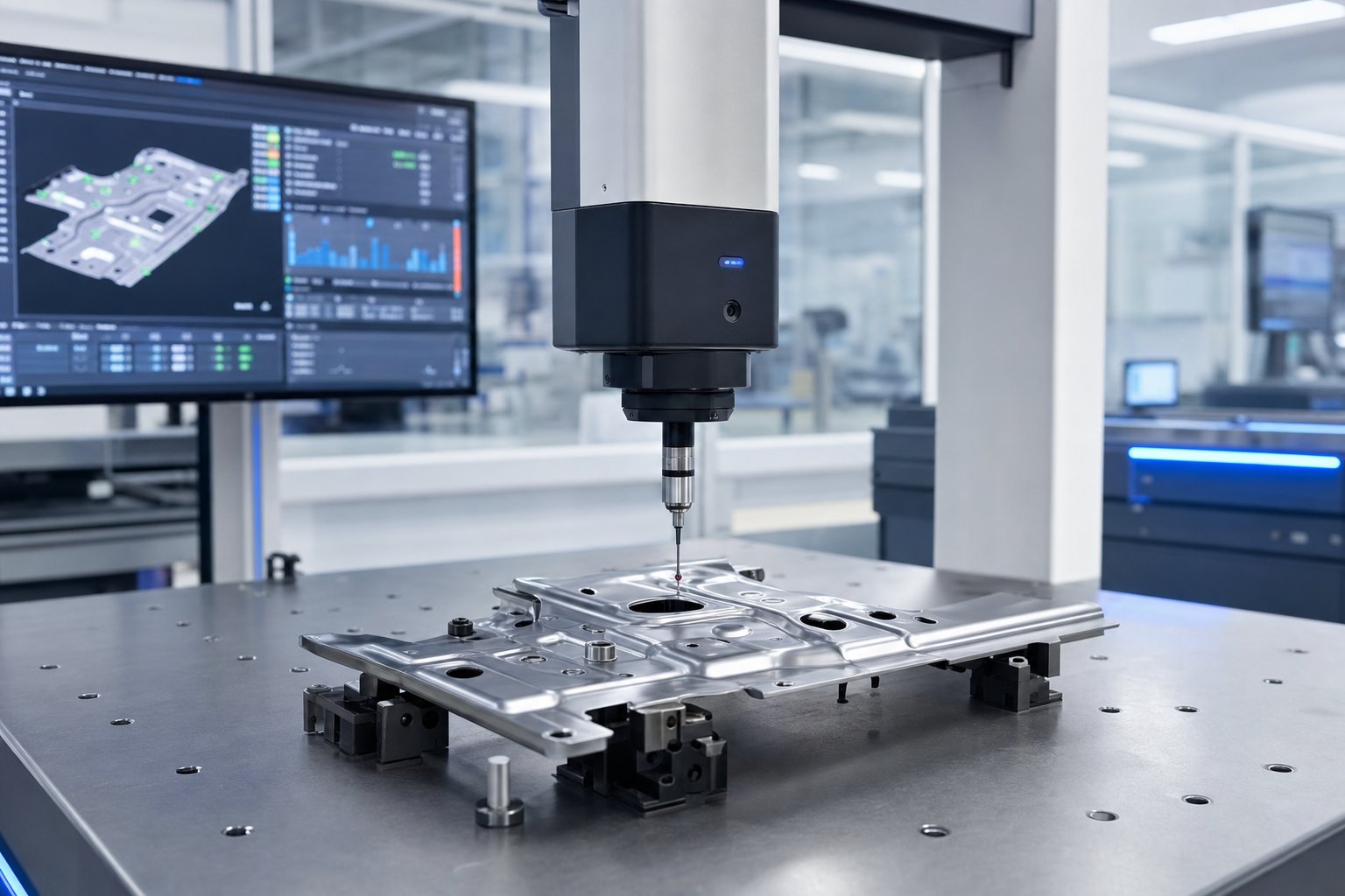
Automated inspection systems integrate directly with press operations to verify dimensional output without slowing production. Vision systems use cameras positioned at the die exit to check feature presence, orientation, and gross dimensional conformance at full press speed. Laser measurement stations sample critical dimensions on ejected parts at defined intervals, feeding data directly into SPC software. CMM (Coordinate Measuring Machine) inspection provides the highest accuracy for first-article verification and periodic audit measurements, typically achieving measurement uncertainty below ±0.002 mm.
Statistical Process Control (SPC) ties all of this data together. Rather than inspecting individual parts and making pass/fail decisions, SPC tracks process trends over time. Control charts reveal whether variation is stable, drifting, or trending toward specification limits. This distinction matters because a stable process with acceptable variation can run unattended, while a drifting process needs intervention before it produces defects.
For automotive and medical OEM customers, these controls formalize into the PPAP (Production Part Approval Process) framework. PPAP requires the factory to demonstrate process capability before shipping production parts, documented through Cpk (Process Capability Index) studies. The AIAG standard requires a minimum Cpk of 1.33 for critical characteristics, meaning the process uses no more than 75% of the available tolerance and remains well-centered within specification limits. Many OEMs require Cpk of 1.67 or higher for safety-critical components, effectively demanding that the process uses less than 60% of the tolerance band.
A Cpk study involves measuring a statistically significant sample, typically 30 or more consecutive parts, calculating the process mean and standard deviation, and demonstrating that the distribution fits well within both upper and lower specification limits. Factories that invest in real-time SPC can monitor Cpk continuously, catching capability degradation within minutes rather than discovering it during end-of-shift audits.
For OEM buyers evaluating a potential stamping partner, ask a direct question: can the factory show you historical Cpk data from similar production programs? A factory that monitors and archives process capability data has a fundamentally different quality culture than one that relies on final inspection alone. This quality infrastructure becomes even more critical when parts serve regulated industries, where application-specific requirements layer additional controls on top of standard stamping practices.
Industry Applications for Progressive Die Stamped Parts
Regulated industries do not just demand tighter tolerances. They impose entire quality management ecosystems that shape how a stamping factory operates from raw material receiving through final shipment. Those requirements vary dramatically depending on where the finished part ends up, and each vertical market brings its own combination of material preferences, dimensional demands, and documentation expectations that an OEM progressive die & stamping factory must satisfy.
Automotive and HVAC Applications
Automotive components progressive stamping accounts for a major share of progressive die production worldwide. The reason is straightforward: modern vehicles contain hundreds of stamped metal parts, and the volumes per platform easily justify progressive tooling investment. Progressive stamped automotive parts range from small electrical terminals to large structural reinforcements, all produced at speeds and consistency levels that no alternative process can match economically.
Common progressive die stamped parts in automotive include:
- Progressive die stamped brackets for engine mounting, body structure, and interior assemblies
- Motor laminations for electric vehicle drive motors and starter motors
- Electrical connectors, terminals, and bus bars in wiring harness systems
- Structural clips and fasteners for body-in-white assembly
- Seat frame components and adjustment mechanisms
What makes automotive unique as a market? IATF 16949 certification. This quality management standard builds on ISO 9001 but adds automotive-specific requirements around advanced product quality planning (APQP), control plans, and failure mode analysis (FMEA). A factory stamping automotive dies must maintain traceability from coil heat lot through finished part, demonstrate process capability through ongoing Cpk monitoring, and respond to quality alerts within hours rather than days. The cost of a line stoppage at an automotive OEM runs into thousands of dollars per minute, which explains why automakers hold their stamping suppliers to the most rigorous qualification standards in manufacturing.
HVAC progressive metal stamping occupies a different engineering space. Here, the critical requirement is consistent flatness and dimensional uniformity across large part populations rather than single-feature precision. Heat exchanger fins, for example, may be geometrically simple, but even minor flatness deviations degrade thermal transfer efficiency when thousands of fins stack together in a condenser or evaporator core.
Typical HVAC progressive stamped parts include:
- Heat exchanger fins and louver patterns
- Mounting brackets and housing components for air handling units
- Fan motor laminations
- Ventilation damper blades
- Refrigerant line clips and support brackets
HVAC parts frequently run in aluminum or coated steel at high speeds, where die wear patterns must be monitored closely to prevent gradual form degradation across long production runs. A fin die producing several hundred strokes per minute generates millions of parts before maintenance, making carbide inserts and in-die force monitoring essential for sustained quality.
Electrical and Medical Device Applications
Electrical connector manufacturing relies heavily on progressive dies because the parts are small, intricate, and needed in enormous quantities. A single connector housing might contain dozens of individual stamped contacts, each requiring precise spring geometry and consistent contact force. Copper and brass alloys dominate this space due to their conductivity, and die designs often exceed 20 stations to achieve the complex multi-bend geometries these contacts demand.
Common progressive stamped electrical components include:
- Terminals and pin contacts for automotive and industrial connectors
- Bus bars for power distribution in EV battery packs
- Shielding cans and EMI enclosures for RF electronics
- Lead frames for semiconductor packaging
- Battery contacts for consumer electronics
Medical progressive stamping introduces the most stringent process controls of any vertical. Parts destined for surgical instruments, implantable devices, or diagnostic equipment must meet biocompatibility requirements and maintain full lot traceability. The manufacturing environment itself comes under scrutiny: ISO 14644-compliant cleanrooms control airborne particulate contamination during stamping and handling of components that will contact patients. FDA regulations under 21 CFR Part 820 require validated processes, documented procedures, and environmental monitoring that go well beyond standard industrial stamping practice.
Progressive stamped medical device parts include:
- Surgical blade blanks and cutting instrument components
- Implant fixation clips and anchors
- Diagnostic device housings and shielding
- Catheter reinforcement rings
- Drug delivery mechanism springs and contacts
Factories serving medical OEMs must maintain material certifications for every coil, record process parameters for each production lot, and retain samples for extended periods to support post-market traceability. The quality system overhead is substantial, but medical device volumes and per-piece pricing reflect that investment.
In-Die Assembly and Secondary Process Integration
One capability that separates advanced stamping factories from basic press shops is in-die assembly, the ability to perform operations beyond forming and cutting without removing the part from the progressive die. Imagine a bracket that needs a tapped hole, a riveted insert, or a welded nut. Traditionally, these features require secondary operations: the stamped part leaves the press, moves to a separate workstation, and undergoes additional handling. Each transfer adds cost, cycle time, and quality risk.
In-die assembly eliminates those transfers by integrating secondary operations directly into the die's station sequence:
- In-die tapping - Thread-forming or thread-cutting heads mounted in the die create tapped holes during the press cycle, delivering a ready-to-assemble part at the die exit.
- In-die welding - Resistance or laser welding stations join secondary components (nuts, pins, contacts) to the stamped part while it remains on the carrier strip.
- In-die insertion - Press-fit bushings, rivets, or contact pins are fed and installed within die stations, producing a sub-assembly rather than a raw stamping.
- In-die bending and riveting - Multiple strip-fed components are brought together, formed over each other, and mechanically fastened within the die.
For OEM buyers, in-die assembly translates directly to lower total cost. Eliminating a secondary tapping operation, for instance, removes a machine, an operator, a fixture, and an inter-process queue from the value stream. Multiply that across several features and several hundred thousand parts per year, and the savings become substantial. It also improves quality because the part never leaves the controlled environment of the die, so positional accuracy between stamped features and added components remains governed by die precision rather than fixture repeatability.
The breadth of industries served and the depth of process integration available within a single progressive die highlight why factory selection matters so much. A supplier capable of running automotive dies under IATF 16949, medical parts under cleanroom protocols, and in-die assembly for electrical connectors operates at a fundamentally different capability level than a shop that simply runs a press. Understanding how to evaluate that capability, and what to look for during qualification, is where most OEM buyers need the clearest guidance.
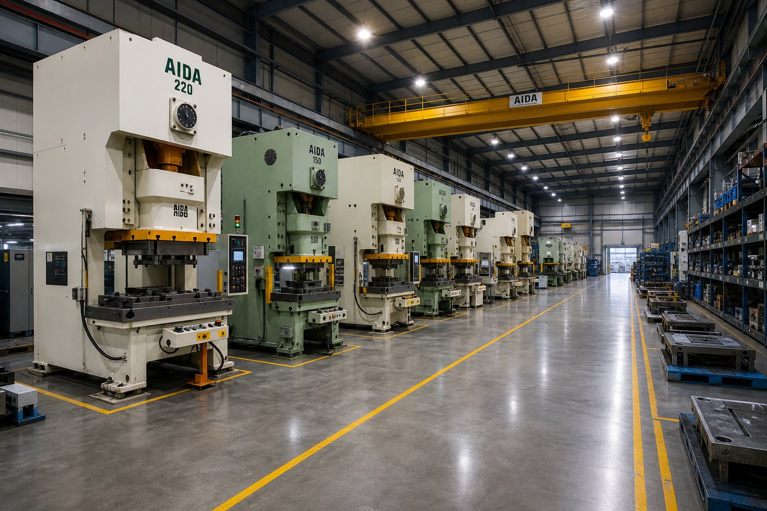
How to Evaluate and Select an OEM Progressive Die Stamping Factory
Knowing which stamping method fits your part and which quality standards apply does not help much if the factory you select cannot deliver on those requirements consistently. Yet most OEM buyers evaluate progressive die manufacturers based on piece price alone, skipping the technical and relational due diligence that determines whether a program actually succeeds over its production lifecycle. A structured qualification framework eliminates guesswork and protects your tooling investment from the start.
Technical Capability Assessment
When you walk a factory floor or review a supplier's capability package, you are looking for evidence that their equipment, tooling expertise, and infrastructure match the demands of your specific program. A stamping die supplier quoting aggressively on price but lacking the right press range or tooling depth will cost you far more in delays, quality issues, and mid-program transfers than a slightly higher piece price ever would.
Here is what to assess during technical evaluation of any progressive stamping company:
- Press tonnage range - Does the fleet cover your current program and foreseeable growth? Look for breadth, not just a single press that barely fits your die. A factory running presses from 30 to 300+ tons can accommodate design evolution without requiring a new supplier.
- Maximum strip width and bed size - Confirms whether the factory can physically run your die, especially important for parts with high station counts that produce long tools.
- Station count capability - Ask about the most complex die they currently run in production. A factory comfortable with 20+ station dies operates at a different engineering level than one topping out at eight.
- In-house tool room - This is non-negotiable for serious programs. Factories that design, build, and maintain dies internally respond faster to engineering changes, control quality more tightly, and reduce lead time risk compared to those outsourcing tooling work.
- Secondary operations and in-die assembly - Can the factory deliver finished sub-assemblies, or will you need additional vendors for tapping, welding, plating, or insertion?
- Material handling systems - Coil storage capacity, servo feed accuracy, and automated part handling at the die exit all signal production maturity.
- Inspection infrastructure - CMM equipment, vision systems, SPC software, and in-die sensing confirm the factory monitors quality rather than just checking finished parts.
During site audits, look beyond the showpiece press line. Check the tool room for active preventive maintenance logs. Review die storage conditions for customer-owned tooling. Verify that calibration stickers on gauges are current. These details reveal whether the quality system operates daily or exists only in documentation binders. Export-grade stamping plants operating prevention-based systems typically achieve defect rates in the 50 to 200 PPM range, while shops relying on end-of-line sorting accept significantly higher levels.
Partnership Structure and Communication
Technical capability alone does not make a reliable OEM metal stamping services partner. The relationship structure, meaning how the factory engages with your team across the full program lifecycle, determines whether that capability translates into consistent delivery. The best progressive die stampings suppliers treat programs as collaborations rather than transactions.
A complete OEM partnership lifecycle typically follows this progression:
- Initial design consultation - The factory reviews your part concept, application requirements, and volume projections before quoting. This is where progressive stamping and fabrication alternatives get discussed openly.
- DFM review - Tooling engineers flag manufacturability concerns, suggest geometry modifications, and recommend material options that improve die longevity and reduce piece cost.
- Prototyping approach - Soft tooling or wire-EDM samples validate part geometry before committing to hardened production tooling.
- Tooling build and tryout - The factory constructs the progressive die, runs first samples, measures results against print, and iterates until dimensions and forming quality meet specification.
- PPAP submission - Dimensional reports, Cpk studies, control plans, and process flow documentation demonstrate production readiness.
- Production ramp-up - Initial low-rate production validates supply chain logistics, packaging, and delivery cadence before full-volume release.
- Ongoing production management - Kanban replenishment, JIT delivery schedules, periodic re-validation, and continuous improvement activities maintain quality and availability over the program's life.
Where do OEM-stamping factory relationships break down? Three common failure modes surface repeatedly:
- Communication gaps - The factory treats your program as order fulfillment rather than partnership. No dedicated engineering contact, no proactive updates on die condition or material changes. As industry practitioners note, suppliers that communicate proactively, flagging potential delays or material issues before they escalate, build trust and enable faster problem resolution.
- Tooling neglect - Preventive maintenance gets deferred to keep presses running, and progressive die wear gradually degrades dimensional output until parts start failing inspection at your assembly plant.
- Inflexible scaling - Demand increases or engineering changes hit a wall because the factory lacks press capacity, tool room bandwidth, or willingness to invest in die modifications.
Preventing these failures comes down to establishing clear expectations during qualification. Define communication cadence, maintenance reporting requirements, and capacity buffers in your supply agreement rather than assuming they will happen organically.
Factories that support the full lifecycle from DFM consultation through scalable mass production, such as YICHEN, give production engineers and procurement teams a single point of engagement for progressive stamping dies requiring multi-station forming, tight repeatability, and volume flexibility. This integrated model, spanning progressive stamping and fabrication under one operational framework, reduces handoff risk and simplifies accountability when programs scale or engineering changes arise.
Ultimately, selecting the right factory is not about finding the cheapest quote. It is about matching technical depth, communication discipline, and partnership commitment to the complexity and lifecycle demands of your program, then verifying those qualities through structured evaluation before committing tooling dollars.
Next Steps for OEM Buyers Ready to Source Progressive Dies
Evaluation frameworks and technical knowledge only generate value when they translate into action. For production engineers and procurement professionals weighing OEM progressive stamping programs, the path forward requires converting the decision criteria covered throughout this guide into a concrete project launch sequence that protects both tooling investment and long-term production outcomes.
Cost-to-Value Decision Framework
Every progressive die & stamping project rests on four interacting variables: tooling investment, per-piece cost, quality requirements, and volume projections. These do not operate independently. A higher tooling investment in carbide inserts and additional stations raises upfront cost but lowers per-piece price and extends maintenance intervals. Tighter tolerance requirements increase tooling complexity but may eliminate downstream assembly problems that carry hidden costs. Volume projections determine how quickly tooling amortizes, but overly optimistic forecasts lock capital into dies that never reach breakeven.
The right progressive die manufacturer reduces total cost of ownership beyond piece price alone. Factories that offer DFM collaboration, in-die assembly, and integrated quality systems eliminate handoffs, secondary vendors, and quality escapes that inflate landed cost. When comparing quotes, evaluate total program cost across the expected production lifecycle rather than isolating any single line item. A supplier quoting higher piece price but delivering PPAP-ready parts with Kanban replenishment and zero sorting may cost less over three years than the lowest bidder requiring constant quality intervention.
Starting Your Progressive Die Stamping Project
Ready to move from research to engagement? These practical steps position your program for a smooth launch:
- Prepare complete part drawings with GD&T callouts - Specify critical dimensions, datum structures, and surface finish requirements. Incomplete prints force suppliers into assumptions that generate quote mismatches and mid-build surprises.
- Define annual volume estimates and lifecycle projections - Include ramp-up schedules, peak demand scenarios, and expected program duration. This information shapes tooling design decisions around die life and maintenance planning.
- Identify material and finish requirements - Specify alloy grade, temper, thickness, and any post-stamping treatments (plating, coating, heat treatment). Material choice affects die design, so locking it early prevents costly tooling revisions.
- Engage potential factory partners early for DFM input - The highest-impact cost reductions happen before tooling design begins. Specialized progressive die manufacturers such as YICHEN offer DFM consultation that helps production engineers optimize part geometry for efficient multi-station forming and scalable mass production.
- Request documented evidence of capability - Ask for Cpk data from similar programs, PPM history, and references from comparable industries. Progressive die stamping services vary enormously in quality infrastructure, and evidence beats claims every time.
The most critical selection criterion for any OEM progressive stamping program is not piece price but demonstrated process capability, meaning a factory that can prove statistical control on parts similar to yours, maintain that control across millions of strokes, and communicate transparently when conditions change.
A well-structured supplier engagement, built on complete specifications, realistic volumes, and early DFM collaboration, compresses lead times, prevents mid-program surprises, and sets the foundation for a partnership that delivers consistent value year over year. The factories that earn long-term OEM relationships are the ones that treat your program as an engineering collaboration from day one, not a purchase order to fill.
Frequently Asked Questions About OEM Progressive Die & Stamping Factories
1. What is a progressive die and how does it differ from a single-stage die?
A progressive die is a multi-station stamping tool where a metal strip advances through sequential operations (piercing, bending, forming, trimming) with each press stroke, producing a finished part every cycle. Unlike a single-stage die that performs one operation per stroke and requires manual handling between steps, a progressive die consolidates all operations into one tool and one press cycle. This eliminates part handling, reduces cycle time, and improves dimensional consistency, making it ideal for high-volume production where OEM factories need to produce thousands or millions of identical metal components efficiently.
2. How much does progressive die tooling cost and when does the investment pay off?
Progressive die tooling typically ranges from approximately $10,000 for simpler tools to $350,000 for complex multi-station builds. The investment pays off through dramatically lower per-piece costs at volume. A die costing tens of thousands adds meaningful cost per part at 5,000 pieces, but at 500,000 pieces that same investment contributes fractions of a cent per unit. The breakeven point depends on part complexity, station count, material, and annual volume. Parts requiring multiple forming operations reach breakeven sooner because the alternative of running separate single-operation setups carries high labor and quality risk. Factories like YICHEN (https://www.yichen-group.com/stamping-die/progressive-stamping-die/) help OEM buyers optimize die designs to maximize return on tooling investment through efficient multi-station forming.
3. What tolerances can progressive die stamping achieve?
Achievable tolerances depend on material type and part complexity. For simple flat operations like piercing and blanking, low-carbon steel and copper alloys hold ±0.03 to ±0.05 mm. Moderate forming with one to two bends typically achieves ±0.05 to ±0.10 mm. Complex multi-bend parts with three or more bends range from ±0.08 to ±0.15 mm. Materials with higher work-hardening rates like stainless steel and aluminum introduce more springback variability. Leading factories can reach positional tolerances as fine as ±0.005 mm on critical features, though this requires higher tooling investment, carbide inserts, and more frequent maintenance cycles.
4. What materials are best suited for progressive die stamping?
The most common materials include low-carbon steel (1008-1010) for automotive brackets and enclosures, stainless steel 300 and 400 series for corrosion-resistant medical and appliance parts, copper alloys (C110, C101) for electrical terminals and bus bars, brass (C260, C360) for connectors and decorative hardware, and aluminum (3003, 5052, 6061) for lightweight automotive and HVAC components. Material selection affects die wear, lubrication needs, press speed, and achievable tolerances. Softer materials like copper enable faster speeds and longer maintenance intervals, while harder alloys like stainless require carbide tooling and aggressive lubrication to prevent galling.
5. How should OEM buyers evaluate and select a progressive die stamping factory?
Evaluate factories across technical capability and partnership structure. Key technical criteria include press tonnage range, maximum strip width, station count capability (ask about their most complex production die), in-house tool room for die design and maintenance, secondary operations and in-die assembly capability, and inspection infrastructure including CMM, vision systems, and SPC software. Beyond equipment, assess communication discipline, DFM collaboration willingness, PPAP documentation quality, and capacity buffers for demand fluctuations. Request Cpk data from similar programs and PPM history. Prevention-based factories typically achieve 50 to 200 PPM defect rates. The most critical factor is demonstrated process capability, not piece price alone.


