


What Stamping Die Components Do Inside a Working Die
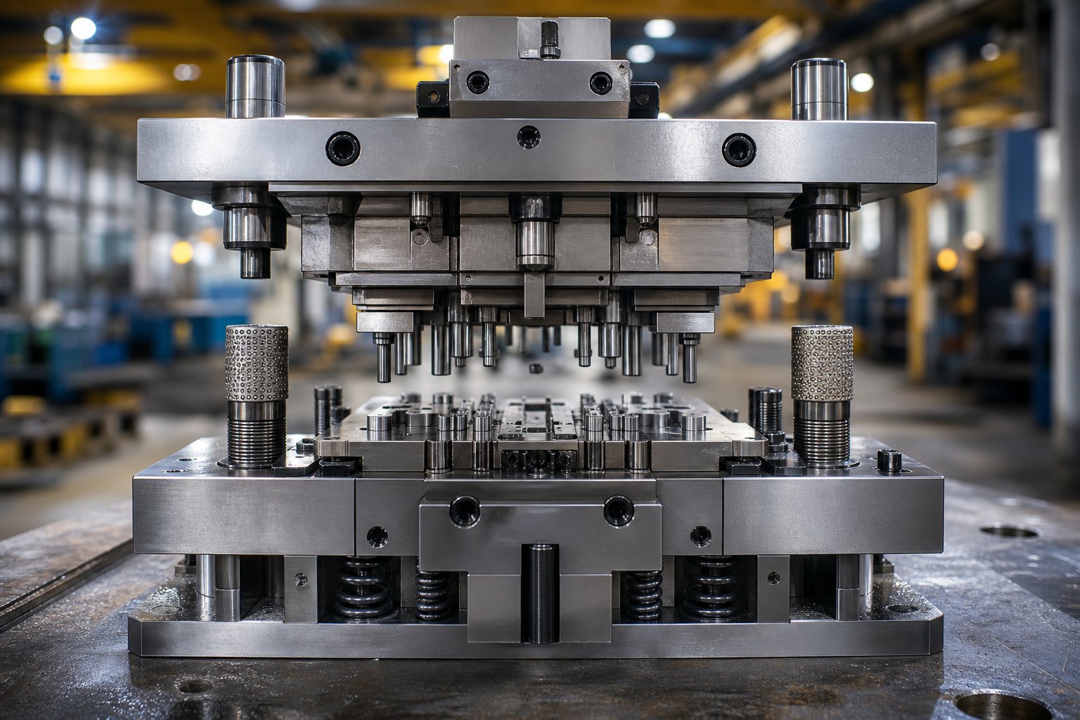
A stamping die is a precision tool assembly that cuts and forms sheet metal into a desired shape every time a press applies force. But here's what most parts lists won't tell you: the individual stamping die components only matter because of how they work together. Each one serves a specific mechanical role - structural support, material control, cutting, forming, or strip management - and they must execute those roles in tight coordination through every single press stroke.
Understanding how die components interact matters far more than memorizing part names. A die is a system, and each component's performance depends on the behavior of everything around it.
Defining Stamping Die Components as a System
So what is a die, really? It's an upper and lower tool set configured to cut, bend, form, or draw metal placed between its halves. A die is used to produce finished parts - repeatedly, at speed, and within tight tolerances. What are dies made of? Hardened tool steels, carbide inserts, precision-ground pins, and engineered spring systems, all mounted to rigid steel plates. Every element exists because the system demands it.
Why Component Knowledge Matters for Tooling Engineers
When you understand each component's function within the larger assembly, troubleshooting becomes systematic rather than guesswork. A burr on your stamped part isn't just a "punch problem" - it could trace back to worn guide bushings allowing misalignment, fatigued springs failing to strip material cleanly, or a die shoe deflecting under tonnage.
How Components Coordinate Through a Press Stroke
Imagine a single press cycle unfolding in milliseconds. Die shoes and guide pins hold the upper and lower halves in rigid alignment. The stripper plate contacts the strip material and holds it flat. Punches descend through the stripper and shear metal against die buttons below. Springs compress, absorbing force and storing energy. On the return stroke, those same springs push the stripper down, clearing the punch from the material so the strip can advance to its next position. Every component fires in sequence - structural, then cutting, then stripping - hundreds of times per minute.
This coordinated action is what separates a functioning stamping die from a collection of steel parts. The chapters ahead break down each component group in detail, starting with the structural foundation that makes everything else possible.
Structural Foundation Components That Hold Everything Together
Every cutting punch, forming steel, and spring system inside a stamping die depends on one thing: a rigid, precisely aligned platform to mount on. The structural tooling components don't cut metal or shape parts directly, but without them, nothing else works as intended. They absorb tonnage, maintain alignment, and resist the lateral forces that would otherwise destroy cutting edges in a matter of hours.
Die Shoes and Their Load Distribution Role
Die shoes are the steel or aluminum plates that form the upper and lower halves of a stamping die set. Think of them as the foundation of a building - everything bolts, dowels, or keys into these plates. Their primary job is distributing press force evenly across the die's working area so that no single component absorbs concentrated loads.
The upper shoe mounts to the press ram; the lower shoe bolts to the press bed. Together, they must remain flat and parallel under tonnage. That's why they're ground or precision-milled to tight tolerances. A warped or undersized die shoe leads to uneven force distribution, which cascades into deflection, punch breakage, and inconsistent part quality.
Die shoe thickness isn't arbitrary. A coining die that compresses metal by squeezing it between upper and lower sections requires a much thicker shoe than a simple bending operation. The rule is straightforward: higher tonnage and wider strip widths demand thicker shoes to resist deflection. Most shoes are steel, but aluminum is gaining popularity in certain applications - it weighs one-third as much, machines quickly, absorbs shock well, and special alloys can give it compressive strength exceeding low-carbon steel.
The lower die shoe typically includes machined or flame-cut holes that let slugs and scrap fall through onto the press bed. These openings also serve as clearances for gas springs and other components mounted below the die surface.
Guide Systems for Upper-to-Lower Alignment
When the press ram descends at speed, the upper and lower die shoes must meet in exactly the same position every cycle. Guide pins and bushings make that happen. These precision-ground components - often manufactured within 0.0001 in. - keep the two halves aligned under full tonnage.
Two basic types exist. Friction-style guide pins are hardened tool steel shafts slightly smaller than the bushing bore. The bushings are typically lined with aluminum-bronze, sometimes embedded with graphite plugs to reduce friction and heat. These pins also provide heeling force, resisting side-to-side movement of the shoes.
Ball-bearing guide pins use hardened pins riding on ball bearings held in an aluminum cage. They reduce friction significantly, allow higher press speeds without heat buildup, and can be manufactured to tighter tolerances than friction pins. They also let the diemaker separate the upper and lower shoes easily during maintenance.
One critical point: guide pins are designed to align the die shoes - not to compensate for a worn or sloppy press ram. Oversizing guide pins to mask press maintenance issues only accelerates wear on the pins themselves and introduces alignment errors that damage cutting components.
Heel Blocks, Keys, and Lateral Force Management
Cutting and forming operations don't always generate force straight down. Angled forms, cam-driven features, and asymmetric blanking all produce lateral thrust - side forces that push the upper die relative to the lower. Heel blocks absorb this thrust so it doesn't transfer to the guide pins.
These precision-machined steel blocks are screwed, doweled, and often welded to both die shoes. One side carries a steel heel plate; the opposing side uses a wear plate made from aluminum-bronze or another dissimilar metal. This dissimilar-metal pairing is intentional - two plates of the same material generate excessive friction, heat, and eventually galling. Box heels can resist thrust in all directions simultaneously.
Dowels and keys round out the structural system. Dowels are hardened, precision-ground pins that locate each die section in its exact position on the shoe. Keys are small rectangular blocks of ground steel set into milled keyways - they both locate and heel die sections, providing resistance to shifting under load. Socket head cap screws fasten everything together with the holding power needed for repeated high-tonnage cycling.
Backing plates deserve mention here too. When hardened punch heads press against die shoe material cycle after cycle, the softer shoe can deform. Backing plates - thin hardened steel plates placed between punch retainers and the shoe - prevent this embedding and distribute point loads over a wider area.
| Component | Function | Failure Consequence | Typical Material |
|---|---|---|---|
| Die Shoes (Upper/Lower) | Rigid mounting platform; distributes press force evenly | Deflection, uneven cutting, punch breakage | Medium-carbon steel or aluminum alloy |
| Guide Pins | Aligns upper and lower die shoes through every stroke | Misalignment, uneven wear on cutting edges, burr variation | Hardened tool steel |
| Guide Bushings | Provides low-friction bearing surface for guide pins | Scoring, excessive clearance, alignment drift | Aluminum-bronze (often with graphite) |
| Heel Blocks | Absorbs lateral thrust from forming and asymmetric cutting | Guide pin deflection, die section shifting, component damage | Tool steel with dissimilar wear plates |
| Dowels | Precisely locates die sections on the shoe | Positional drift of working components after maintenance | Hardened ground steel |
| Keys | Locates and heels die sections against lateral movement | Section shifting under asymmetric load | Precision-ground tool steel |
| Backing Plates | Prevents punch heads from embedding into softer die shoe | Shoe deformation, punch height variation, inconsistent shut height | Hardened steel (HRC 58-62) |
Undersized or neglected structural components don't fail loudly - they fail gradually. A die shoe that deflects 0.002 in. under load won't break anything immediately, but it changes punch-to-die clearance across the strip width. Guide pins that score from insufficient lubrication allow progressive misalignment that accelerates wear on every cutting edge in the tool. These problems compound over thousands of strokes, making root-cause diagnosis difficult unless you understand what the structural layer is supposed to deliver: absolute rigidity and repeatable alignment, every cycle, under full tonnage.
With that foundation locked in place, the next layer of the system - the punches, die buttons, and forming steels that actually shape sheet metal - can do their work with the precision they were designed for.
Cutting and Forming Components That Shape the Metal
Rigid alignment and load distribution mean nothing if the die tools that actually contact the sheet metal aren't engineered correctly. Punches, die buttons, die blocks, matrix plates, and forming steels are the components that do the physical work - shearing, bending, drawing, and embossing material into finished geometry. Their design, relationship to each other, and the gap between them determine whether you get a clean part or a scrap bin full of rejects.
How Punches and Die Buttons Work Together
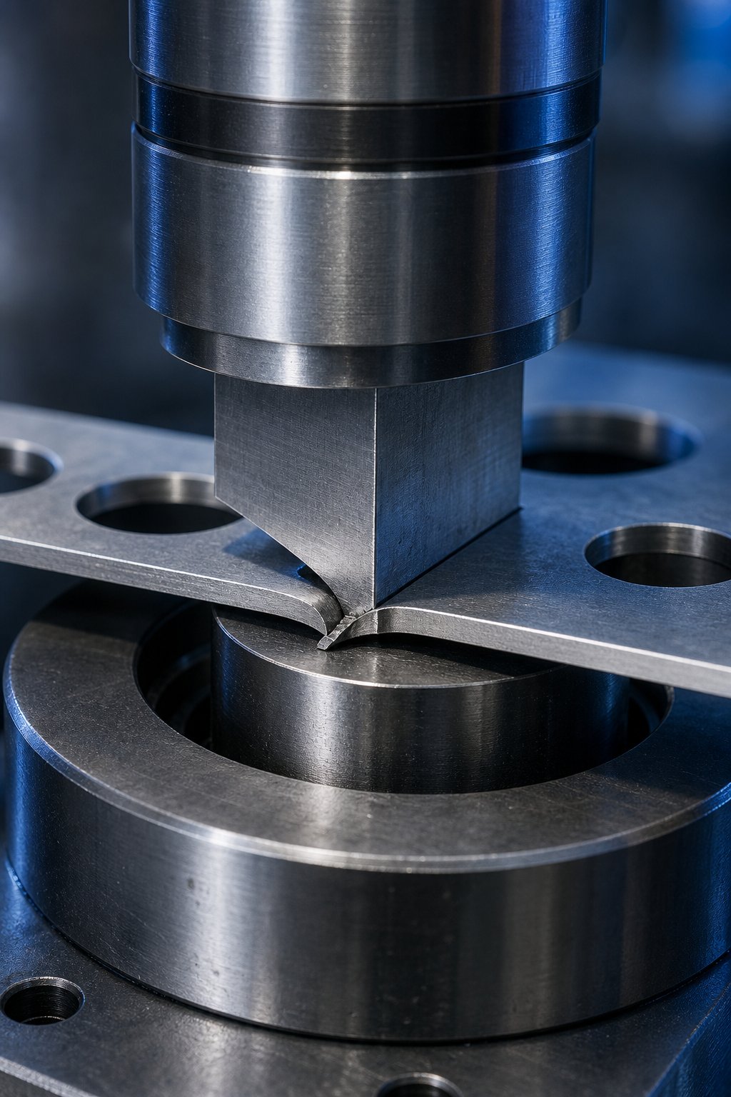
The fundamental relationship in any sheet metal punch and die system is straightforward: the punch is the male cutting tool that descends into a mating female opening - the die button (also called a die insert or matrix). The punch pushes material into or through that opening, and the interaction between their edges is what actually severs the metal.
During a press stroke, the punch contacts the sheet and begins pushing it downward. The material deforms slightly around both the punch edge and the die button edge - the amount of deformation depends on ductility, thickness, and the clearance between the two cutting edges. As the punch continues downward, it cold-extrudes the metal, creating the sheared portion of the cut known as the cut band. Once the material's shear strength is exceeded, it fractures and breaks away, producing the breakout zone on the cut edge.
Die buttons sit in machined pockets within the die block or a matrix plate and must be retained securely against both downward cutting force and the lateral pressure of material flowing during the cut. Three common retention methods keep buttons locked in place:
- Press-fit retention - the button is ground with a slight interference fit and pressed into a precision-bored pocket. Simple, compact, and effective for round buttons, but requires a hydraulic press for removal during maintenance.
- Ball-lock retention - a spring-loaded ball engages a groove machined into the button's outer diameter. This allows quick removal and installation without pressing, making it popular in high-changeover environments.
- Keyed retention - a key or flat machined on the button prevents rotation, critical for non-round shapes where angular orientation matters. Often combined with press-fit or shoulder retention.
The die block itself - the plate that houses all the die buttons and cutting openings - must be thick enough to support cutting forces without deflection and hard enough to resist wear at the cutting edges. In some configurations, a separate matrix plate holds the buttons while the die block beneath provides structural support and slug clearance passages.
Punch Types and Their Specific Applications
Not every hole or feature in a stamped part requires the same punch geometry. Stamping die punches come in a range of configurations, each tailored to specific operations:
- Plain (solid) round punches - the most common type, used for standard circular piercing and blanking. Durable, easy to resharpen, and available in standard catalog sizes.
- Shaped punches - custom profiles for rectangular slots, D-shapes, keyholes, or any non-circular geometry required by the part design.
- Pilot punches - precision-ground pins that enter previously pierced holes to register the strip before cutting. They don't cut material; they locate it. Critical in progressive dies where cumulative feed error destroys part accuracy.
- Notching punches - designed to remove material from the edge of a strip or blank, creating notches, tabs, or relief features that enable subsequent bending or forming.
- Lancing punches - cut and bend material simultaneously without fully separating it from the strip. Used to create tabs, louvers, or partial features that remain attached.
- Stepped or shoulder punches - feature multiple diameters along their length for improved alignment, better load distribution, and controlled engagement with the die button.
- Hollow or tubular punches - incorporate an internal cavity for slug ejection, reducing the tendency for slugs to stick to the punch face during retraction.
Forming steels - sometimes called forming punches - are a separate category entirely. These components don't cut material; they reshape it. Bends, draws, embossments, and coined features all require precision-machined forming steels whose profiles match the desired part geometry exactly. Their radii, draft angles, and surface finish directly control material flow during forming.
Clearance Between Punch and Die and Its Effects on Part Quality
The distance between the punch edge and the die button edge - the cutting clearance - is one of the most consequential specifications in any die. It's typically expressed as a percentage of sheet thickness per side. A common starting point is about 10% of material thickness per side. For example, cutting 0.050-in.-thick steel with 10% clearance means 0.005 in. of gap per side, or 0.010 in. total diameter difference between punch and button.
But 10% isn't universal. Harder, higher-strength materials generally benefit from larger clearances, while softer, more ductile materials can use reduced values. The consequences of getting it wrong show up immediately on the part edge:
Insufficient clearance causes compressive failure in the material during cutting. You'll see increased punch shock, accelerated wear on both punch and button, higher cutting forces, and more frequent resharpening cycles. The slug tends to stay compressed in the die button - good for slug retention, but at the cost of tool life. Punch deflection and chipping become real risks, especially on thin cross-section punches.
Excessive clearance produces tensile failure. The material stretches and rolls before fracturing, creating larger burrs and rolled edges on the part. Stripping forces drop because less material grips the punch, but slug pulling becomes a serious problem - the slug can ride back up with the punch and land on the die surface, damaging the next part or the die itself.
This connects directly to an often-overlooked aspect of die button design: slug retention geometry. A standard die button isn't just a hole - it incorporates a straight land section at the top followed by angular relief below. The straight land creates a slight compression fit that holds the slug in the button after it's cut. Too short a land and slugs can drop through prematurely or get pulled back. Too long a land and slugs stack up, eventually pushing back against the punch.
When slug pulling does occur, solutions target the dies and punches directly. Commercially available slug-control buttons use machined slots or barbs inside the matrix to grip the slug. Reverse-tapered buttons - where the bore gets slightly smaller toward the clearance opening - hold slugs in compression. Spring-loaded ejector pins inside the punch face push slugs away on the downstroke. Air vents drilled through the punch eliminate vacuum pockets that suction slugs upward during retraction.
The interplay between clearance, slug retention, and part quality is a balancing act. There's no single correct answer - it depends on material grade, thickness, punch geometry, press speed, and production volume. What matters is understanding that these metal punches and die openings form a system where changing one variable shifts the behavior of everything else in the cut zone.
Cutting and forming components do their job in fractions of a second, but they can't do it alone. The strip material must be positioned exactly right before every hit - and that's the job of an entirely different set of components responsible for guiding, lifting, and registering the strip through the die.
Strip Control and Positioning Components in Sheet Metal Stamping Dies
A perfectly ground punch and a precisely bored die button will still produce scrap if the strip material isn't in the right place when they meet. In progressive sheet metal stamping dies, the strip feeds forward between every press stroke - advancing one pitch length at a time through a series of stations. Any positional error at one station accumulates at the next. By the time the strip reaches the final cutoff, even a few thousandths of an inch of drift can push critical features out of tolerance.
That's why stamping die design dedicates an entire category of components to one job: controlling exactly where the strip sits - vertically, laterally, and longitudinally - at the moment the press fires.
Pilot Pins and Precision Strip Registration
Pilot pins are the final-authority positioning components in a progressive die. These precision-ground pins - typically held to tolerances within 0.0002 in. on diameter - descend into previously pierced holes in the strip just before cutting or forming operations engage. Their job isn't to cut; it's to locate. They pull or nudge the strip into exact registration so that every subsequent operation lines up with what came before.
Here's how the sequence works. At an early station in the die, a piercing punch creates a pilot hole - a round hole whose sole purpose is receiving the pilot pin at downstream stations. As the strip feeds forward, it arrives at the next station slightly imprecise. Feed rolls have mechanical tolerances. The strip itself can stretch, camber, or shift laterally. When the upper die begins its descent, the pilot pin enters the pilot hole before any punches contact the material. A tapered nose on the pin guides the strip into position, correcting minor feed errors.
This correction capability is critical. In a progressive die running at 200+ strokes per minute, cumulative feed errors compound quickly. Without pilots re-registering the strip at every station, hole-to-hole distances, bend locations, and trim lines would drift progressively further from nominal. Pilots essentially reset the positional accuracy at each station, breaking the chain of accumulated error.
Pilot pin diameter is sized relative to the pilot hole - typically 0.001 to 0.002 in. smaller than the hole to allow entry without deforming the hole edges. Too tight, and the pin can elongate or bell-mouth the pilot hole over repeated cycles. Too loose, and it fails to register the strip accurately. The pilot hole itself must be pierced cleanly, with minimal burr, to avoid interference with pin engagement.
Strip Lifters and Their Feed Clearance Function
Between press strokes, the strip needs to move forward freely. But formed features, die buttons, and other components protrude above or sit flush with the die surface - obstacles that would snag the strip during feeding. Strip lifters solve this by elevating the strip above the die surface during the feed portion of the cycle, creating clearance for the strip to advance without dragging.
Three common lifter types handle different situations:
- Spring-loaded pin lifters - small round pins set into bored holes in the die block, pushed upward by compression springs. They support the strip at discrete points and retract under press force when the die closes. Simple, compact, and effective for flat or lightly formed strips.
- Rail-type lifters - continuous bars running along the strip edges, supported by multiple springs. They provide consistent lift height across the full strip length and prevent edge droop on wide materials. Common in dies where the strip needs several inches of clearance over formed features.
- Bullet-nose or guided lifters - similar to pin lifters but with a radiused top that prevents the strip from catching during lateral movement. Used where the strip tends to shift sideways during feeding.
Lifter height matters more than you might expect. As feed-release timing studies demonstrate, the distance the strip lifts off the die surface directly affects how much extra material pulls through the feed unit during die closure. A die positioned 36 inches from the feed unit with 4 inches of stock-lifter travel can introduce over 0.2 in. of extra material between the feeder and die - enough to cause overfeed errors if timing isn't compensated. The higher the lift, the more this effect amplifies, making lifter height a process variable that ties directly into feed-roll closure timing.
Bypass Notches for Strip Clearance in Progressive Dies
Sometimes, lifting the strip isn't enough. Certain die components - forming steels, cam drivers, or protruding die sections - extend above the strip travel plane and would physically block the material from advancing. Bypass notches solve this by removing or adding material to the strip at specific locations, allowing it to pass over or around obstructions during feeding.
The purpose of bypass notches in stamping dies breaks down into two types:
- Negative bypass notches - material is removed from the strip (typically by a piercing punch at an earlier station) to create a gap or slot. When the strip feeds forward, this notch provides clearance where a die component would otherwise interfere. Common when the obstruction is narrow or when removing material doesn't weaken the carrier strip unacceptably.
- Positive bypass notches - instead of removing strip material, the die component itself is relieved or shaped with a raised feature that the strip can pass over. In some designs, a small tab of material is left standing on the strip to ride above a die section. This approach preserves strip strength in applications where removing material would compromise carrier stability.
Designing negative and positive bypass notches in sheet metal stamping dies requires balancing strip strength against clearance needs. Remove too much material and the carrier weakens, allowing the strip to buckle or twist during feeding. Don't remove enough and the strip catches on die components, causing jams, misfeeds, or die crashes. Notch placement must also account for how the strip lifts - a notch that provides clearance at full lift height may not clear the obstruction if a lifter spring fatigues and delivers reduced elevation.
Common Strip Control Problems and Their Component-Level Causes
When strip control fails, the symptoms show up immediately in part quality - but tracing back to the responsible component requires understanding the system. Here are the most frequent issues:
- Short feeds or overfeed - caused by incorrect feed-roll timing relative to lifter height, worn feed rolls slipping on lubricated strip, or feed length not compensating for material pulled during die closure.
- Pilot hole elongation - indicates pilot pins are too tight to the hole, engaging while the strip is still moving, or the strip is inadequately lifted during feed so pilots drag through the material.
- Strip buckling between stations - caused by excessive lifter height that creates too much slack, or by weakened carrier strips from overly aggressive bypass notch designs.
- Lateral drift - stock guides worn or improperly spaced, allowing the strip to shift sideways. Misaligned lifter rails can also push the strip off-center.
- Strip catching on die components during feed - bypass notches undersized, lifter springs fatigued (reduced lift height), or formed features deeper than originally planned.
- Inconsistent registration - pilot pins worn, pilot holes burred from previous stations, or pilot engagement happening too late in the press stroke (after cutting begins).
Spring Strippers Versus Solid Strippers
One more positioning component deserves attention because it bridges strip control and cutting function: the stripper plate. Its job is holding the strip flat against the lower die during cutting and then stripping it off the punches during retraction. Two fundamentally different designs exist, and the choice between them shapes die behavior significantly.
Spring strippers (also called pressure pad strippers) are spring-loaded plates mounted to the upper die that surround the cutting punches. As the die closes, the stripper contacts the strip first, pressing it flat against the die surface under spring pressure before any punch touches the material. This hold-down eliminates camber and crossbow in the strip, prevents the material from lifting or shifting during the cut, and - critically - holds the strip flush to the die surface during punch withdrawal so the punches can retract cleanly without pulling the material upward. As die design expert Art Hedrick notes, spring strippers eliminate the deflection and binding problems inherent to solid strippers, making them the preferred choice for most progressive die applications.
Solid strippers (bridge strippers or plate strippers) are rigid plates bolted directly to the lower die. They don't move - the strip simply threads beneath them. They're cheaper to manufacture, require no springs, and need minimal maintenance. But they offer no hold-down pressure during cutting, meaning the strip is free to lift, shift laterally, or bind between punches during entry. This freedom of movement increases stripping force, can deflect thin punches, and in worst cases results in punch breakage from material hammering against the solid plate during retraction.
For progressive dies running at production speeds, spring strippers are almost always the better investment. The few dollars saved by using a solid stripper rarely offset the risk of punch breakage, increased burr, and inconsistent strip registration that come with uncontrolled material during the cutting cycle.
Strip control components are quiet performers - they don't visibly shape the part the way punches do. But they determine whether those punches hit the right target. The force that drives these lifters, strippers, and pressure systems back to their starting positions after every stroke comes from the next critical component group: the springs and gas cylinders that manage energy throughout the die assembly.
Spring Systems and Force Management Inside the Die
Every moving component in a die assembly - strippers, pressure pads, lifters, knockout pins - needs a force to push it back into position after the press stroke. That force comes from springs and gas cylinders strategically placed throughout the tool. These aren't passive accessories. They're active press die components that control stripping pressure, blank-holding force during forming, and the return motion of every moving plate in the system. Get the spring selection wrong, and you'll see slug pulling, inconsistent draw depths, and stripper plates that tilt instead of retracting evenly.
Die Springs and Their Load-Deflection Characteristics
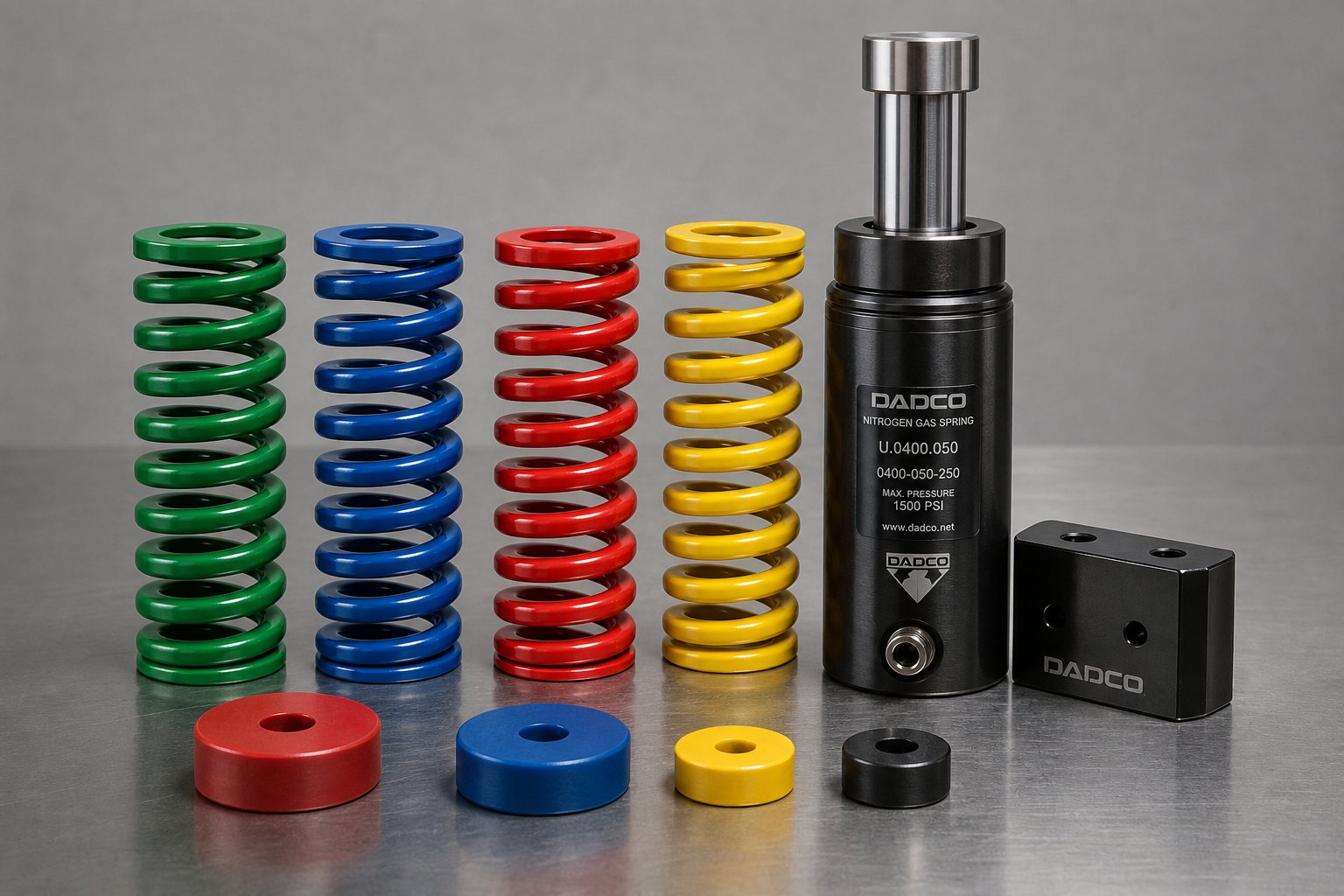
Mechanical die springs are helically coiled compression springs engineered for high loads and repeated cycling under extreme stress. You'll recognize them by their color coding - a vinyl coating system that indicates working load capacity at a glance. Light-duty springs (green or blue) suit low-force stripping, while extra-heavy-duty springs (red or yellow) handle high-tonnage blank holding and forming pad applications.
Three wire shapes define the mechanical options. Rectangular wire produces the highest force for a given spring size and complies with ISO 10243, but the wire twists during compression, introducing stress that limits fatigue life. Round wire handles cyclic stress better but delivers less force per unit size. Oval wire splits the difference - optimizing load capacity and stress resistance in a single geometry.
Selecting the right spring means balancing several interdependent factors:
- Preload - the initial compression applied during installation. Preload ensures the spring delivers force immediately when the die opens, but it reduces available working travel and accelerates fatigue.
- Working deflection - how far the spring compresses during the actual press stroke. This must match the press stroke length minus any preload compression.
- Total deflection capacity - the maximum safe compression before coils bind solid. Exceeding this destroys the spring instantly.
- Fatigue life - directly tied to the percentage of total deflection used per cycle. Springs loaded to 50% of their capacity last dramatically longer than those consistently pushed to 75%.
Closed-end springs provide flat mounting surfaces, while open-end versions may need grinding for stability. Either way, spring cans - cylindrical housings - should surround every spring in a die pad plate that bottoms out during operation. These cans contain debris if a spring fractures and prevent coil fragments from damaging the die or stamped parts.
Nitrogen Gas Springs for High-Force Applications
When a machine die requires more force than mechanical springs can deliver in the available space, nitrogen gas springs step in. These cylinders use compressed nitrogen - charged between 10 and 200 bar - to generate force through a sealed piston. The result is significantly higher output from a smaller footprint.
The practical advantages go beyond raw force. A nitrogen spring delivers force immediately upon contact with no preload required, since the gas is already pressurized inside the cylinder. This means the entire stroke length is available as working travel - a major advantage over mechanical springs that sacrifice travel to preload. Force delivery is also more consistent across the stroke. Where a mechanical spring's force increases linearly with compression (following Hooke's Law), a gas spring provides a relatively flat force curve, producing nearly the same pressure at the beginning and end of its travel.
That consistency matters for forming operations. A draw pad backed by nitrogen springs applies uniform blank-holding pressure throughout the draw depth, reducing wrinkling and tearing that inconsistent force can cause. Nitrogen springs also offer a guaranteed minimum service life - typically one million cycles - with no fatigue-related breakage or debris shedding that mechanical springs suffer from over time.
The tradeoff? Cost and monitoring. Nitrogen springs require pressure checks to detect slow leaks, and their internal seals eventually degrade. Best practice from experienced die designers limits piston travel to 85% of rated capacity to extend cylinder life. Remote pressure monitoring through Bluetooth or wired sensors provides automatic alerts if force drops - a feature unavailable with mechanical springs that simply fatigue silently until parts start failing.
Spring Placement Strategy Within the Die Assembly
Choosing the right spring type and rating solves only half the problem. Where you position springs within the die determines whether the stripper plate or pressure pad moves evenly - or tilts destructively to one side.
Imagine a rectangular stripper plate supported by four springs clustered near the center. Under stripping load, the plate's outer edges deflect downward while the center lifts first. That tilt means punches on the plate's perimeter stay engaged with the strip longer than those near the center, creating uneven stripping forces and potential punch breakage. The solution: distribute springs evenly across the plate area, spacing them to balance the load.
Several placement principles apply consistently across press die components:
- Never locate springs directly over a stock balancer - they provide no hold-down force to the part being formed in that position.
- Springs placed halfway between a pad balancer and the material deliver only half their rated force to the workpiece.
- In progressive dies, all upper pressure pads that push stock lifters down as the die closes must share the same travel length. Unequal travel causes the strip to tilt, pulling parts out of registration across stations.
- For large stripper pads, pad balancers prevent tipping when a new coil enters the die - the moment when no strip material supports the pad from below.
Urethane pads - solid polyurethane blocks or tubes - fill a niche between springs and gas cylinders. They offer high force in compact spaces, absorb shock well, and resist oil and debris contamination. But their deflection capacity is limited (typically 20-25% of free height), and they build heat under rapid cycling, which degrades their force output over time. They work best for light stripping, knockout applications, or as supplementary force elements where space won't accommodate a coiled spring.
| Spring Type | Force Range | Deflection Capacity | Best Application | Maintenance Needs |
|---|---|---|---|---|
| Mechanical Die Spring (Rectangular Wire) | Medium to very high (load rated by color) | Up to 50% of free length (25-30% recommended for longevity) | Stripping, blank holding, pressure pads | Visual inspection for cracks; replace at set intervals or when force drops |
| Mechanical Die Spring (Round/Oval Wire) | Light to medium | Up to 50% of free length | Light stripping, lifters, return springs | Same as rectangular; less prone to torsional fatigue |
| Nitrogen Gas Spring | High to very high (adjustable via charge pressure, 10-200 bar) | Full stroke available (no preload loss); use 85% of rated travel | Draw pads, high-force stripping, forming operations requiring consistent pressure | Pressure monitoring (Bluetooth/wired sensors); seal replacement at end of service life |
| Urethane Pad | Light to medium | 20-25% of free height | Knockout, light stripping, supplementary force in tight spaces | Monitor for heat degradation and permanent set; replace when height loss exceeds 5% |
When springs fatigue - and they all eventually do - the effects ripple through the entire die. Reduced stripping force allows slugs to pull back with the punch, landing on the die surface and damaging subsequent parts. Weakened pad springs let material shift during forming, producing inconsistent bend angles or draw depths. Fatigued lifter springs reduce strip elevation, causing the material to drag on die components during feeding. None of these symptoms point obviously to a spring problem unless you're measuring force output regularly rather than waiting for visual failure.
Spring systems define how much force acts on every moving component and how evenly that force distributes across the working area. But force alone doesn't determine die performance - the materials those springs, punches, and forming steels are made from dictate how long they survive under load before wear changes their behavior.
Material Selection Criteria for Die Components
A punch ground to perfect geometry and held in precise alignment will still fail early if it's made from the wrong steel. Material selection is the hidden variable that separates metal stamping dies lasting 50,000 hits from those surviving five million. Yet it's one of the most under-discussed aspects of die engineering - often reduced to "use D2" without explaining why, when to deviate, or what tradeoffs that choice introduces.
The reality is that every steel stamping dies component faces a specific combination of wear, impact, and heat. A blanking punch endures abrasive sliding against sheet metal edges. A forming steel absorbs repeated shock loads. A pilot pin needs dimensional stability above all else. Choosing one grade for everything either over-engineers simple components (wasting money) or under-engineers critical ones (causing premature failure). Matching the material to the job is where die stamping economics actually live.
Common Tool Steel Grades and Their Properties
Four tool steel grades handle the vast majority of sheet metal die applications. Each occupies a specific performance niche defined by its chemistry, achievable hardness, and behavior under load.
D2 tool steel is the workhorse of cold-work stamping. It's a high-carbon, high-chromium, air-hardening grade engineered for maximum wear resistance in applications where abrasion is the primary failure mode. D2 reaches 58-62 HRC after heat treatment, forming dense chromium carbides that resist the sliding wear of sheet metal passing over cutting edges. It's the default choice for blanking punches, die buttons, and any component facing long production runs against carbon steel or stainless. The tradeoff? D2 is relatively brittle at full hardness. It resists gradual wear excellently but can chip or crack under sudden impact - making it a poor choice for heavy forming operations or dies that experience shock loading from material variations.
A2 tool steel occupies the middle ground between wear resistance and toughness. Also air-hardening, A2 reaches 57-62 HRC but contains less chromium carbide volume than D2. This gives it noticeably better impact resistance while still providing good wear life. A2 is the practical choice for forming dies, blanking tools, gauges, and precision tooling where moderate production volumes don't justify D2's brittleness risk. It also machines more easily in the annealed state, reducing initial tooling cost.
S7 tool steel is a shock-resisting grade built for impact. Where D2 and A2 prioritize carbide hardness, S7 prioritizes toughness - the ability to absorb sudden loads without fracturing. It heat-treats to 54-58 HRC, lower than D2, but its microstructure dissipates impact energy rather than transmitting it to crack initiation points. S7 excels in forming punches, cam drivers, heavy-duty piercing in thick material, and any application where the tool experiences interrupted or variable loading. When a punch chips repeatedly despite correct clearance and alignment, switching from D2 to S7 often solves the problem immediately.
M2 high-speed steel fills a specialized role where heat is the enemy. M2 retains its hardness at elevated temperatures - a property called red hardness - making it suitable for operations that generate significant frictional heat at the cutting edge. In die stamping, this typically means high-speed piercing of thin materials or applications where lubrication is minimal. M2 reaches 60-65 HRC and maintains cutting performance where D2 would soften and wear rapidly. Its downside is cost and machinability: M2 is substantially more expensive and more difficult to grind than cold-work grades.
| Grade | Hardness (HRC) | Wear Resistance | Toughness | Best Application |
|---|---|---|---|---|
| D2 | 58-62 | Excellent | Fair to moderate | Long-run blanking, piercing punches, die buttons in carbon and stainless steel |
| A2 | 57-62 | Good | Good | Moderate-volume forming dies, blanking tools, precision tooling with impact exposure |
| S7 | 54-58 | Moderate | Excellent | Forming punches, cam drivers, heavy piercing, shock-loaded components |
| M2 | 60-65 | Very good (retains at high temperature) | Fair | High-speed piercing, minimal-lubrication operations, heat-intensive cutting |
When to Specify Carbide Inserts Over Tool Steel
What happens when even D2 wears too quickly? In ultra-high-volume applications - production runs exceeding one million parts - tool steel resharpening intervals may become unacceptably frequent. This is where carbide inserts enter the picture.
Tungsten carbide (cemented carbide) offers wear resistance that extends die life by 500-1000% compared to traditional tool steels in certain applications. Carbide cutting inserts maintain razor-sharp edges through millions of cycles, dramatically reducing downtime for resharpening and die maintenance. For high-volume automotive connectors, electrical terminals, or medical components stamped in abrasive stainless steel, carbide often pays for itself within the first production year through reduced tool changes alone.
The limitation is brittleness. Carbide is extremely hard (typically 75-90 HRA, equivalent to roughly 68-74 HRC) but has very low impact toughness. A carbide punch that hits a misfed strip or encounters a material double-up will shatter rather than chip or deform. This restricts carbide to controlled, low-impact operations: fine blanking, precision piercing, shallow coining, and applications where strip feeding is highly reliable and material consistency is guaranteed.
Carbide inserts are also expensive to manufacture and modify. Unlike tool steel punches that can be resharpened on a surface grinder in minutes, carbide requires diamond grinding wheels and specialized fixtures. Design changes or corrections demand new inserts rather than rework. For these reasons, carbide is specified only after the die design is fully validated and production parameters are locked - never for prototype or short-run tooling.
Matching Material Selection to Production Volume
The connection between material choice and production economics is straightforward once you frame it correctly. You're not choosing the "best" steel - you're choosing the most cost-effective steel for the expected tool life demand.
For short production runs under 100,000 parts, A2 tool steel offers an economical balance of performance and cost. It machines faster than D2, requires less aggressive heat treatment, and tolerates the minor misalignments common in prototype or low-volume dies without catastrophic chipping. The lower wear resistance is acceptable because the tool won't accumulate enough hits for wear to become the limiting factor.
Medium-volume production - 100,000 to 1,000,000 parts - typically justifies D2 or equivalent high-chromium cold-work steels. At this scale, resharpening intervals directly affect production scheduling. D2's superior edge retention means longer runs between maintenance stops, fewer die setups, and more consistent part quality across the production window. The higher initial material and machining cost is offset by reduced per-part tooling expense.
High-volume applications exceeding 1,000,000 parts push the calculation toward carbide inserts or advanced coated tool steels. At these quantities, even small improvements in tool life translate into significant savings. Advanced surface coatings like TiN (titanium nitride) or DLC (diamond-like carbon) can extend the service life of D2 components by 30-50% by reducing friction and adhesive wear - a middle-ground option that avoids carbide's brittleness while extending maintenance intervals beyond uncoated tool steel capabilities.
Hardness itself isn't the goal - it's a means to an end. A sheet metal die component hardened to 62 HRC resists wear beautifully, but that same hardness makes it vulnerable to microchipping if the application involves any impact component. Dropping to 58 HRC sacrifices some wear life but gains enough toughness to survive intermittent shock loading. The right answer depends on which failure mode will actually retire the tool first: gradual wear or sudden fracture. Experienced die engineers make this call based on material thickness, part geometry, press speed, and historical failure data from similar applications.
Material grade determines how long each component survives. But identical steel grades perform differently depending on the die type they're installed in - progressive, transfer, compound, or combination configurations each place unique demands on their components that shift both sizing and material requirements.
How Components Differ Across Die Types
The same tool steel, the same press tonnage, the same sheet metal - yet the component lineup inside the die changes dramatically depending on whether you're running a progressive, transfer, or compound configuration. Each type of stamping dies solves a different production problem, and that problem dictates which components are present, which are absent, and how the remaining ones interact. A progressive die dedicated to high-speed connector stamping looks nothing like a transfer die forming automotive body panels, even though both rely on the same fundamental building blocks covered in earlier sections.
Understanding which components belong to which die type - and why - prevents over-engineering simple tools and under-specifying complex ones.
Progressive Die Components for High-Volume Strip Processing
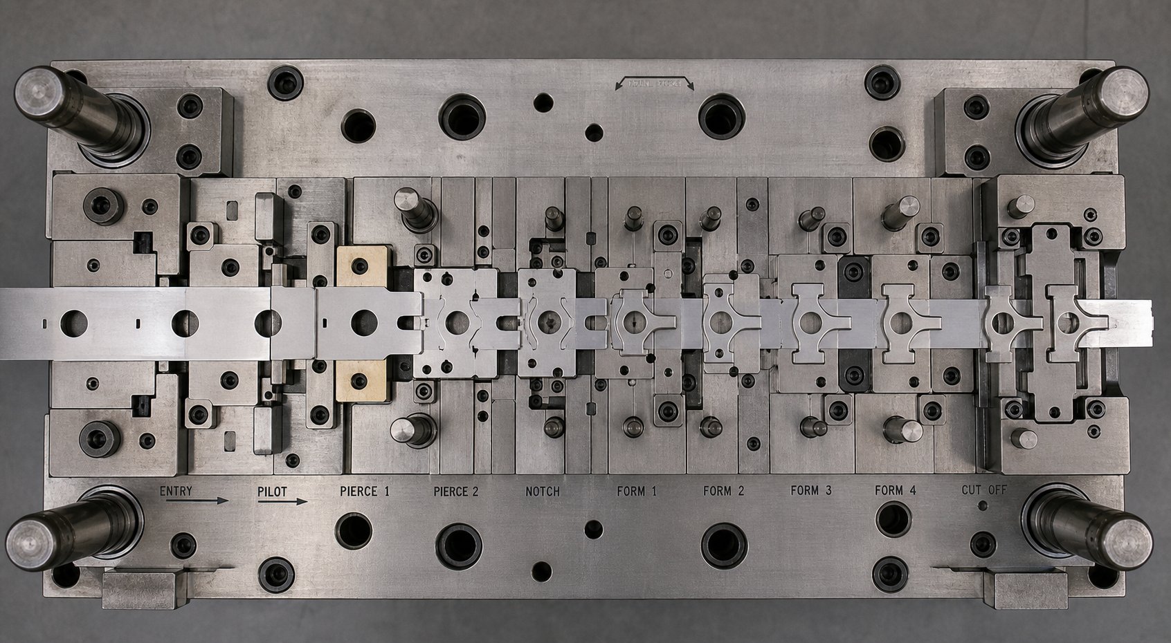
Progressive dies are the most component-dense type of stamping dies in regular production. The strip feeds through multiple stations within a single die block, advancing one pitch length per press stroke while remaining connected to the carrier strip from start to finish. The part is separated only at the final station. This continuous-strip approach demands an entire subsystem of components that single-station dies simply don't need.
Pilot pins appear at nearly every station, re-registering the strip before each cut or form operation engages. Strip lifters - spring-loaded pins or rail-type bars - elevate the material between strokes so it can advance without snagging on die components below. Bypass notches, both positive and negative, allow the strip to pass over protruding forming steels or cam drivers that would otherwise block feed motion. Stock guides confine the strip laterally, preventing drift that would misalign features across stations.
The carrier strip itself is a design element unique to progressive dies. Engineers must leave enough material connecting adjacent parts to maintain strip integrity through all stations - too narrow a carrier and the strip buckles or tears; too wide and material waste climbs. Carrier design directly influences lifter placement, pilot hole location, and where bypass notches can be positioned without weakening the structure.
Progressive metal stamping die sets also incorporate timing-sensitive components. Spring strippers must compress and release in sync with pilot engagement. Feed releases must open at precisely the right crank angle to allow strip advancement without disturbing registration. These timing demands make progressive dies the most mechanically complex configuration, but the payoff is speed - progressive die stamping can quickly produce large runs of small parts with exacting tolerances while performing multiple operations simultaneously.
Transfer Die Components and Part Nesting
Transfer dies flip the strip-management paradigm entirely. Instead of keeping the workpiece connected to a carrier strip, the first station blanks or separates the part from the coil immediately. From that point forward, the individual blank travels between stations via a mechanical transfer system - fingers, rails, or walking beams that lift, move, and place the part at each successive die station.
This separation eliminates the need for pilot pins, strip lifters, bypass notches, and carrier strip management. In their place, transfer dies require a different component set focused on part location rather than strip control:
- Nest guides - precision-machined pockets or locator pins that position the blank accurately at each station. These must allow quick loading, provide positional accuracy within tolerance, and permit fast unloading after each operation. Nest guides should also incorporate fool-proofing - additional locating features that prevent non-symmetric parts from being placed incorrectly.
- Part locators and gauge pins - hardened pins or blocks that reference off previously formed features, edges, or holes to maintain positional consistency as geometry changes from station to station.
- Lifting and ejection mechanisms - pneumatic or spring-loaded devices that raise the finished part clear of the nest so the transfer mechanism can grip it for the next move.
- Transfer rail clearance features - reliefs machined into the die structure that allow the mechanical fingers or grippers to enter and exit without colliding with forming steels or die sections.
The absence of a carrier strip gives transfer dies a significant advantage for certain applications. Transfer die stamping is suitable for manufacturing deep drawn parts because the blank is free on all sides - no carrier restricts material flow into the draw cavity. It's also ideal for large parts where a progressive strip would be impractically wide, or for geometries requiring operations on both sides of the workpiece.
Automotive stamping die applications favor transfer configurations for exactly this reason. Large body panels, structural brackets, and deep-drawn housings need unrestricted material flow and multi-directional forming that a connected carrier strip would physically prevent. The tradeoff is speed - transfer mechanisms cycle slower than progressive strip feeding - and cost, since transfer die stamping requires multiple separate dies rather than one integrated die block.
Compound and Combination Die Configurations
Compound dies represent a fundamentally different approach to component arrangement. Instead of spreading operations across multiple stations, a compound die performs blanking and piercing simultaneously in a single press stroke - producing a finished flat part in one hit. The mechanical trick that makes this possible is an inverted configuration where conventional component roles reverse.
In a standard die, the punch mounts to the upper shoe and the die opening sits in the lower. A compound die inverts part of this arrangement: the blanking die is mounted in the upper shoe while the blanking punch sits in the lower. Simultaneously, piercing punches mounted in the lower shoe push upward through the blank as it's being cut from the strip. The blank is both cut from the strip and pierced in the same stroke, trapped between upper and lower cutting elements acting in opposing directions.
This inverted layout requires a specialized component found only in compound dies: the shedder. Because the blank is cut into an enclosed die cavity with no angular relief (the cavity must remain straight-walled to maintain dimensional accuracy), the part has no natural path to exit. The shedder - a spring-loaded or knockout-actuated plate that slides inside the die cavity - pushes the finished blank out of the upper die after each stroke. Without it, blanks would stack inside the cavity and eventually jam the tool.
Shedders are made from medium-alloyed tool steel hardened to 56-58 HRC and ground to slide freely within the die opening. They serve a dual function: ejecting the part and, during the cutting stroke, acting as a pressure pad that holds the blank flat while piercing punches penetrate from below. This produces notably flat parts - a key advantage of compound dies over progressive configurations where parts can dish or bow during cutting.
Combination dies blur the line further by integrating both cutting and non-cutting operations in a single stroke - piercing and bending, blanking and forming, or cutting and drawing performed simultaneously. These require careful component sequencing within the same die space: cutting elements must engage before forming elements to prevent material distortion during the shear, and spring pressures must be balanced to avoid tilting the workpiece mid-stroke.
| Die Type | Unique Components | Production Speed | Part Complexity | Typical Application |
|---|---|---|---|---|
| Progressive | Pilot pins, strip lifters, bypass notches, stock guides, carrier strip design, spring strippers | High (200-1500+ SPM for small parts) | Moderate to high (limited by strip attachment) | Electrical connectors, brackets, terminals, small complex parts in high volume |
| Transfer | Nest guides, part locators, transfer rail clearances, ejection mechanisms, fool-proofing features | Moderate (15-80 SPM typical) | High (unrestricted geometry, deep draws, multi-side features) | Automotive body panels, structural components, deep-drawn housings, large parts |
| Compound | Shedder, knockout plate, transfer pins, inverted die/punch arrangement, straight-wall die cavity | Moderate to high | Low (flat parts only - blanking + piercing) | Washers, gaskets, flat laminations, wheel blanks, any part requiring high flatness |
| Combination | Integrated cutting + forming steels, sequenced engagement timing, balanced spring systems | Moderate | Moderate (cutting + one forming operation) | Parts requiring a cut and bend or cut and draw in a single stroke to reduce stations |
In-Die Assembly and Emerging Component Roles
The traditional boundary of a stamping die - cut, form, and eject - is expanding. In-die assembly integrates joining or fastening operations directly into the press stroke, eliminating downstream handling and secondary operations. Components that enable this include in-die nut or stud insertion stations, clinch punch and anvil sets, rivet setting mechanisms, and in-die welding electrodes.
These additions change the component landscape significantly. A progressive die with an in-die assembly station needs additional press force capacity at that station, localized backing support in the die shoe, and timing coordination to ensure the fastener is inserted only after forming is complete but before the part separates from the strip. The die structure must accommodate fastener feed mechanisms - blow tubes, track feeds, or escapement systems - all within the die envelope.
The choice between progressive, transfer, compound, and combination configurations isn't just about part geometry or production volume. It determines the entire component inventory, the complexity of the spring system, the material grades required for each working element, and ultimately the engineering effort needed to specify every dimension in the tool. That specification process - sizing structural members to tonnage, setting clearances to material properties, and calculating spring forces to match forming requirements - is where all the component knowledge converges into a single coherent design.
Component Sizing and Specification Logic in Stamping Tool and Die Design
Knowing what each component does is one thing. Knowing how to size it for a specific application is where die design becomes engineering rather than assembly. Every specification in a stamping tool and die - shoe thickness, guide pin diameter, spring force, clearance value, pilot pin size - traces back to a process requirement. Press tonnage, strip properties, and part geometry are the inputs. Component dimensions are the outputs. Get the math wrong, and the die either under-performs or self-destructs.
The discipline here is matching each component's capacity to the forces and tolerances it will actually encounter in production - nothing more, nothing less. Over-sizing wastes material and press capacity. Under-sizing invites deflection, wear, and early failure. The goal is precision engineering: every dimension justified by a calculation or a known design rule.
Sizing Structural Components to Press Tonnage
Press tonnage is the starting variable for structural component sizing. The total cutting and forming force the die must withstand dictates minimum requirements for die shoes, guide pins, and backing plates - the components that absorb and distribute that force without deflecting beyond acceptable limits.
Die shoe thickness scales directly with tonnage and die area. A larger die footprint under higher tonnage needs a thicker shoe to prevent bowing at center span. While no universal formula exists for every application, experienced tooling engineers use finite element analysis or established guidelines to target deflection below 0.001 in. under full load. For moderate-tonnage progressive dies (under 100 tons), shoes in the 2.0-3.0 in. thickness range are common. High-tonnage applications - automotive draws exceeding 500 tons - may demand shoes 4.0 in. or thicker, sometimes reinforced with ribs or T-slot configurations to maximize stiffness without excessive weight.
Guide pin diameter follows a similar logic. The pins must resist bending deflection under the lateral forces generated during cutting and forming. Larger dies with higher tonnage and wider strips require larger-diameter pins - typically ranging from 1.5 in. for small dies up to 3.0 in. or more for large transfer die sets. Ball-bearing guide systems handle higher speeds and tighter alignment but demand even more precise bore tolerances in the bushings.
Backing plate thickness is determined by the hardness differential between punch heads and the die shoe. Standard backing plates run 0.500-0.750 in. thick, hardened to 58-62 HRC. The critical sizing question isn't thickness alone - it's whether the plate area is large enough to spread concentrated punch loads below the yield strength of the shoe material beneath it. A cluster of small-diameter punches concentrated in one area may require a thicker or wider backing plate than a single large punch distributing force over a broader footprint.
Clearance Specification Based on Material and Thickness
Punch-to-die clearance is the most consequential per-side dimension in any cutting operation. It's specified as a percentage of workpiece thickness, and that percentage varies by material type, hardness, and desired edge quality.
The general starting point for mild steel is approximately 10% of material thickness per side. For a 0.060 in. mild steel strip, that means 0.006 in. clearance per side - or 0.012 in. total diameter difference between punch and die button. But this baseline shifts significantly with material properties:
- Soft materials (aluminum, copper, brass) - 5-8% per side. Lower clearance produces cleaner cuts because the ductile material would otherwise stretch and roll excessively before fracturing.
- Mild steel and low-carbon grades - 8-12% per side. The standard range that balances cut quality against tool life.
- High-strength steel and stainless - 12-18% per side. Harder materials develop higher cutting forces; increased clearance reduces the force required to initiate fracture and minimizes punch wear.
- Advanced high-strength steels (AHSS) - 15-20% per side. These grades demand even more clearance because of their resistance to fracture initiation. Tighter clearances cause secondary shear, dramatically accelerating punch wear.
The calculation itself is simple: multiply material thickness by the recommended percentage to get per-side clearance. But the engineering judgment lies in choosing the right percentage - and that choice depends on priorities. Tighter clearance produces smaller burrs and cleaner cut bands but shortens tool life and increases cutting force. Wider clearance extends resharpening intervals but produces larger burrs and more edge rollover. As MISUMI's engineering guidance notes, modern development increasingly favors 11-20% clearance values to reduce tooling strain and extend operational life, even at slight expense to edge aesthetics.
Pilot pin sizing follows a different logic. The pin diameter is specified relative to the pilot hole - typically 0.001-0.002 in. undersize to allow smooth entry without deforming the hole edges. The pilot hole itself is pierced at an early station and must be held to tight tolerances (typically +0.0005/-0.0000 in.) so the pin can register the strip accurately at downstream stations. Too much clearance between pin and hole defeats the purpose of piloting; too little causes hole elongation over repeated cycles.
Guide pin clearance within bushings operates at a different scale entirely. Precision progressive dies typically specify guide pin fits within 0.005 mm (0.0002 in.) to maintain upper-to-lower alignment under full tonnage. Ball-bearing guide systems achieve even tighter alignment by eliminating the clearance variable entirely - the balls preload between pin and bushing, producing zero effective play during the stroke.
Design Considerations for Complex Part Geometry
Simple flat blanking and piercing operations follow the sizing rules above with minimal complication. Complex part geometry - deep draws, multi-angle bends, stepped forms, and compound curves - introduces additional specification variables that interact with each other in non-linear ways.
Draw operations present the clearest example. The die pad plate (blank holder or draw pad) must deliver enough force to prevent wrinkling without over-restraining the material and causing splits. As stamping die expert Art Hedrick explains, even minor deflection in a drawing pad results in loss of flow control - wrinkling between the pad face and die surface. Pad thickness must resist bending under full blank-holding force while fitting within the press shut height constraints. The force itself is typically 25-33% of the drawing force for simple cylindrical shells, but complex shapes may require finite element simulation to determine actual blank-holder pressure distribution.
Draw pad geometry adds another layer. Flat pads work for round shells and rectangular boxes with flat flanges. Contoured parts - automotive fenders, inner doors, structural rails - need shaped pads that follow the part's binder surface. An undevelopable wrap (where the pad forces material to buckle before punch contact) produces stretch in the center of the part, which is useful for certain geometries but can create surface defects on Class A panels where appearance matters.
Forming steel profiles demand careful attention to radii. Internal bend radii smaller than the material thickness create stress concentrations that crack the workpiece. Die radii that are too large waste material by requiring more draw depth. The relationship between punch nose radius, die opening radius, and material thickness determines whether the operation is a draw, a stretch, or a combination - and each mode requires different force calculations and different spring specifications for the blank holder.
Lifter spacing and quantity depend on strip width, material thickness, and the weight the lifters must support. A 6-in.-wide strip of 0.060 in. steel is substantially heavier per linear foot than a 1-in.-wide strip of 0.020 in. aluminum - and requires more lifters, stronger springs, and higher lift forces to elevate cleanly during feeding. Spacing lifters too far apart on wide strips allows the material to sag between support points, creating a wave that interferes with piloting accuracy.
These interacting variables - tonnage, clearance, pad force, forming radii, spring rates, and lifter loads - are where metal stamping tool and die specification becomes genuinely complex. Changing one parameter cascades into others: increasing draw depth requires more blank-holder force, which demands stiffer nitrogen springs, which adds weight to the upper die, which requires thicker shoes to resist the additional moment loads. Each decision has downstream consequences that experienced engineers trace through the entire system before committing to a design.
For non-standard sizing decisions - particularly where part geometry forces unusual component interactions or material flow patterns that don't fit standard reference tables - collaboration with specialized tooling partners becomes practical rather than optional. YICHEN offers custom stamping die solutions specifically for these design-intensive challenges, connecting tooling engineers with resources for die structure optimization, clearance engineering, and material flow analysis when standard catalog calculations no longer apply. This kind of support is most valuable during the specification phase, before tool steel is cut and errors become expensive to correct.
Specification logic gives every component its dimensions on paper. What happens after those components go into production - how they wear, when they fail, and whether to replace them with standard or custom alternatives - defines the die's real-world lifecycle and the long-term cost of keeping it running.
Maintenance and Sourcing Decisions for Die Components
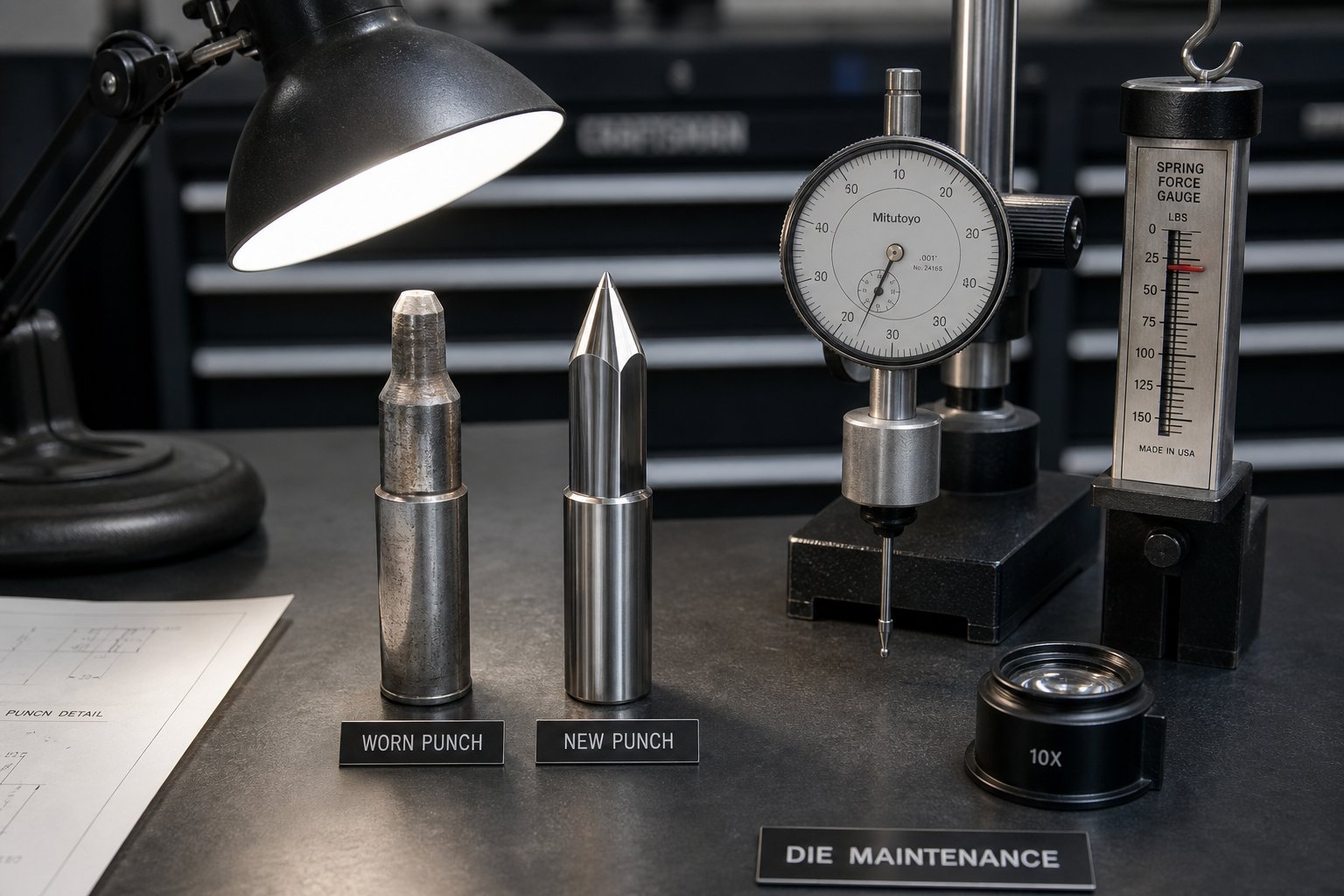
Every die component has a finite service life. The punches dull, springs fatigue, guide pins score, and die buttons lose geometry one press stroke at a time. None of these failures happen suddenly in most cases - they develop as measurable wear patterns that experienced tooling engineers learn to read like diagnostic signals. The difference between a stamping operation that runs profitably and one hemorrhaging money on unplanned downtime often comes down to one question: do you catch wear before it becomes failure, or after?
Equally important is the sourcing decision that follows every maintenance event. When a component reaches end-of-life, do you pull a standard die replacement from a catalog, or does the application demand a custom-engineered part? That choice affects lead time, cost, and ultimately whether the repaired die performs as well as - or better than - when it was new.
Recognizing Wear Patterns and Scheduling Maintenance
Stamping dies don't announce their degradation with a single dramatic event. They whisper through gradually shifting part quality - a burr growing taller by a few thousandths, a critical dimension drifting toward the edge of tolerance, a press load creeping upward shift after shift. Recognizing these signals early is what separates preventive maintenance from emergency repair.
The most reliable wear indicators map directly to specific die components:
Punch tip rounding is the earliest and most common sign of cutting component wear. As the cutting edge radius grows from use, it requires more force to initiate material fracture. The measurable result? Burr height increases on stamping parts. A fresh punch producing 0.001 in. burrs that now produces 0.003 in. burrs has lost significant edge sharpness. Many shops set a burr-height threshold - commonly 10% of material thickness - as the trigger for resharpening.
Guide pin scoring shows up as visible scratches or galling marks on the pin surface. This doesn't mean the pin itself failed - it means the die shoes are misaligning under load, forcing the pin to absorb lateral forces it wasn't designed to carry. Scoring is a symptom of a structural problem: press ram looseness, heel block wear, or inadequate lateral force management. Replacing a scored pin without fixing the root cause guarantees the replacement will score just as quickly.
Spring force decay is invisible until you measure it. A die spring that delivered 500 lbs of force at working height when new may deliver only 380 lbs after 200,000 cycles - a 24% loss that shows up as inconsistent stripping, slug pulling, or variable forming depth. Experienced shops measure spring force with a calibrated gauge at scheduled intervals rather than waiting for part quality to deteriorate.
Die button bell-mouthing - the gradual enlargement and rounding of the die button's cutting edge at its entry face - directly affects slug retention and cut-edge quality. As the entry radius grows, material rolls inward before fracturing, producing larger rollover zones on the stamped part. In severe cases, bell-mouthing allows slugs to pull back through the enlarged opening and land on the die surface.
A structured maintenance cadence ties these indicators to action intervals:
- Cutting components (punches, die buttons, trim steels) - Inspect every 50,000-100,000 strokes. Measure burr height and bright-band width on sample parts. Resharpen when burr exceeds threshold. Typical resharpening removes 0.002-0.004 in. per grind. Track cumulative removal to forecast replacement.
- Guide systems (pins, bushings, heel blocks) - Inspect weekly or every 100,000-300,000 strokes. Check for scoring, measure clearance between pin and bushing with a dial indicator. Replace bushings when clearance exceeds 0.001 in. beyond specification.
- Spring systems (die springs, nitrogen cylinders, urethane pads) - Test force output monthly or every 100,000 strokes using a spring tester or force gauge. Replace mechanical springs when force drops below 85% of rated value. Check nitrogen spring pressure at every die setup.
- Strip control components (pilot pins, lifters, stock guides) - Inspect every 100,000-200,000 strokes. Measure pilot pin diameter for wear. Check lifter spring force and confirm lift height meets specification. Replace worn pilots before hole elongation becomes a registration problem.
- Structural components (die shoes, backing plates, dowels) - Full dimensional audit during major overhaul (annually or every 500,000-1,000,000 strokes). Check shoe flatness and parallelism. Replace backing plates showing any surface deformation or embedment marks.
The key insight from operations running dies and stamping lines at high volume: power and force trends serve as an early warning system even before part quality shifts. A steady rise in press load, current draw, or energy per stroke often signals blade dulling or increased friction - prompting maintenance action before scrap rates climb. Shops running SPC on critical dimensions can detect Cp/Cpk drift that correlates to component wear, triggering inspection before tolerance limits are breached.
Practical life-extension measures complement scheduled maintenance. Tooling coatings - TiN, CrN, or DLC applied to punches and forming steels - reduce friction and extend intervals between resharpening by 30-50%. Proper lubrication matched to the workpiece material prevents adhesive wear (galling) that accelerates edge degradation. Planning preventive overhauls at 70-80% of expected life avoids the risk of mid-run failures that halt production and compound repair costs.
When Standard Catalog Components Are Sufficient
Not every worn component needs a custom replacement. The stamping components industry supports a robust catalog ecosystem - standard punches, die buttons, guide pins, bushings, springs, and retainers available in thousands of sizes and configurations from multiple suppliers. For common geometries and standard die configurations, catalog parts offer compelling advantages.
Speed: A standard die spring or round punch ships within days, sometimes next-day. When production is down and a component needs immediate replacement, catalog availability eliminates engineering lead time entirely.
Cost: Standard parts are produced in enormous volumes, amortizing tooling and quality system costs across millions of units. A catalog die button costs a fraction of a custom-machined equivalent in the same tool steel.
Proven reliability: Standard stamping components embody decades of collective engineering refinement. Their dimensions conform to industry specifications (ISO, DIN, NAAMS), and their performance data - load ratings, wear life, dimensional tolerances - is well-documented and publicly available. When you specify a standard component, you know what you're getting without custom qualification testing.
Multiple sourcing: Standard components are available from numerous suppliers across different regions. If one vendor faces disruption, alternatives exist. This supply chain resilience is particularly valuable for high-volume stamping dies where a single missing component can idle an entire press line.
The decision to use standard parts is straightforward when these conditions are met: the required geometry matches a catalog offering, the clearance values fall within standard ranges, the material grade and hardness conform to what suppliers stock, and the application doesn't impose unusual load paths or environmental conditions that exceed standard component ratings.
For most maintenance replacements - resharpened punches returned to stock diameter, worn bushings replaced with catalog equivalents, fatigued springs swapped for same-size color-coded replacements - standard components are the correct and economical choice. The engineering is already done. The testing is already proven. The supply chain is already built.
Choosing Custom-Engineered Components for Complex Applications
Standard catalogs solve common problems. But dies and stamping operations frequently present problems that aren't common - non-standard punch geometries dictated by complex part features, unusual clearances required by exotic materials, proprietary lifter configurations driven by unique strip layouts, or bypass notch designs that no catalog addresses.
Custom stamping components become necessary when any of these conditions exist:
- Non-standard clearances - workpiece materials outside the typical mild-steel-to-stainless range (beryllium copper, titanium, advanced high-strength steels) that require clearances no standard die button offers.
- Complex punch profiles - shaped punches matching proprietary part features that don't correspond to any catalog geometry. These require wire-EDM or precision grinding from raw tool steel blanks.
- Unusual retention or mounting - components that must integrate with legacy die structures using non-standard mounting configurations, hole patterns, or retention methods.
- Integrated function components - elements combining multiple functions (a lifter that also serves as a gauge pin, or a stripper insert that incorporates a bypass relief) that don't exist as single catalog items.
- Performance-critical applications - situations where standard tolerances aren't tight enough, standard materials aren't hard enough, or standard coatings don't resist the specific wear mechanism at play.
The total cost comparison between custom and standard isn't just unit price. Custom components carry engineering time, tooling charges, qualification testing, longer lead times, and single-source dependency. But they also deliver optimized performance, extended maintenance intervals, and the ability to solve problems that standard parts fundamentally cannot address. For high-volume production, that performance advantage compounds across millions of cycles - a custom punch lasting 500,000 hits between resharpening versus a standard punch requiring maintenance every 100,000 hits represents a 5x reduction in downtime events.
The practical decision framework mirrors what the engineering procurement community recommends: use standard parts wherever they adequately meet requirements, reserve custom components for applications where standard solutions fall short, and consider modified standard parts - catalog items with secondary machining operations - as a middle ground when a component is 80% right out of the catalog and the remaining 20% can be added through targeted modification.
For engineers facing custom component challenges - particularly design-heavy problems involving burr control, clearance optimization for exotic materials, complex lifter or bypass notch configurations, or proprietary forming geometries - specialized tooling partners offer both engineering support and manufacturing capability that general-purpose machine shops lack. YICHEN provides custom stamping die component solutions spanning die structure through individual component engineering, supporting the full specification-to-production cycle for non-standard applications where catalog offerings reach their limits. This type of partnership is most valuable when the component challenge is genuinely novel - not a simple size substitution, but a design problem requiring tooling expertise to solve correctly the first time.
Whether standard or custom, every sourcing decision feeds back into the maintenance cycle. Standard components simplify future replacements because the supply chain is already established. Custom components demand documentation - detailed drawings, material specs, and heat-treatment records - so the next replacement can be manufactured identically without re-engineering from scratch. The shops that manage dies profitably over their full lifecycle are the ones that make this decision deliberately at every maintenance event, balancing immediate availability against long-term performance and building a component history that makes each subsequent decision faster and more informed.
Frequently Asked Questions About Stamping Die Components
1. What are the main components of a stamping die?
A stamping die consists of several component groups working together: structural foundation parts (die shoes, guide pins, bushings, heel blocks, backing plates), cutting and forming components (punches, die buttons, forming steels), strip control elements (pilot pins, lifters, stock guides, bypass notches), spring systems (mechanical die springs, nitrogen gas springs, urethane pads), and the stripper plate. Each group serves a specific mechanical function, and their coordinated interaction during every press stroke determines part quality, tool life, and production efficiency.
2. How do you determine the correct punch-to-die clearance?
Punch-to-die clearance is specified as a percentage of workpiece material thickness per side. For mild steel, the standard starting point is approximately 10% per side. Softer materials like aluminum use 5-8%, while high-strength steels require 12-18% or more. The choice balances cut quality against tool life - tighter clearance produces smaller burrs but accelerates punch wear, while wider clearance extends resharpening intervals but increases edge rollover. Material grade, thickness, press speed, and desired edge quality all factor into the final specification.
3. What is the purpose of bypass notches in progressive stamping dies?
Bypass notches provide clearance for the strip material to pass over or around die components that protrude above the strip travel plane during feeding. Negative bypass notches remove material from the strip at an earlier station, creating a gap that clears the obstruction. Positive bypass notches relieve or shape the die component itself so the strip can pass over it. Designing these notches requires balancing strip strength against clearance needs - removing too much material weakens the carrier, while insufficient relief causes jams and misfeeds. YICHEN (https://www.yichen-group.com/stamping-die/) supports engineers with custom solutions for complex bypass notch configurations in progressive die applications.
4. When should you use nitrogen gas springs instead of mechanical die springs?
Nitrogen gas springs are preferred when the application demands higher force output from a smaller footprint, more consistent force delivery across the full stroke, or when forming operations require uniform blank-holding pressure throughout the draw depth. Unlike mechanical springs that increase force linearly with compression, nitrogen springs provide a relatively flat force curve. They also deliver force immediately with no preload sacrifice, making the entire stroke length available as working travel. The tradeoffs include higher cost, the need for pressure monitoring to detect seal degradation, and recommended travel limits of 85% of rated capacity to extend service life.
5. How do you choose between standard catalog and custom-engineered die components?
Use standard catalog components when the required geometry, clearance, material grade, and load ratings match available offerings - they ship faster, cost less, and carry proven reliability from decades of refinement. Custom-engineered components become necessary when applications involve non-standard clearances for exotic materials, complex punch profiles matching proprietary part features, integrated multi-function elements, or performance-critical situations where standard tolerances or materials fall short. For high-volume production, custom parts that last 5x longer between maintenance events can justify their higher upfront cost through reduced downtime. Specialized partners like YICHEN (https://www.yichen-group.com/stamping-die/) provide full engineering support for non-standard component challenges spanning design through production.


