


What Metal Stamp Tool and Die Really Means
Search for "metal stamp tool and die" and you'll find everything from $15 hand stamps sold on craft marketplaces to $200,000 progressive dies engineered for automotive production lines. That range creates real confusion for buyers trying to source the right solution. Let's fix that.
Defining Metal Stamp Tool and Die
Metal stamp tool and die refers to the broad category of precision instruments used to mark, cut, form, or shape metal through applied force, ranging from handheld marking stamps to complex industrial dies that mass-produce sheet metal components.
The stamping definition shifts depending on context. In a jewelry workshop, stamping means pressing a design into a surface. On a factory floor, it means transforming flat sheet metal into finished parts at speeds exceeding 1,500 strokes per minute. Both are valid, but they represent entirely different investments, lead times, and engineering requirements.
Artisan Stamps vs Industrial Stamping Dies
So what is a stamping tool in practical terms? Here's where the spectrum matters:
- Hand stamps are manually operated hardened steel tools struck with a hammer to leave impressions like serial numbers, logos, or letters. They're portable, low-cost, and suited for low-volume or one-off marking tasks.
- Machine stamps integrate with hydraulic presses or dot peen systems for repeatable, higher-volume marking on production lines.
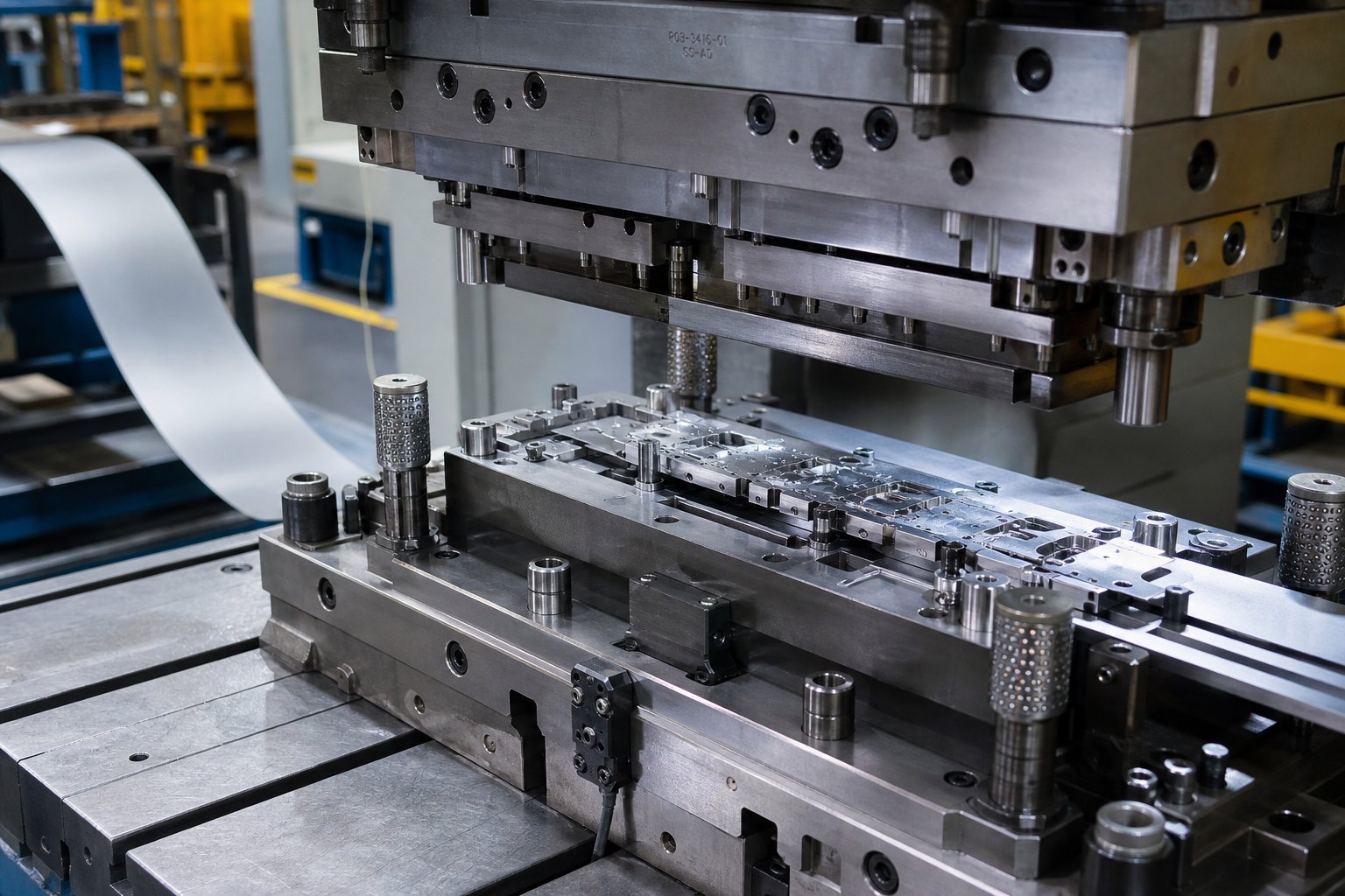
- Industrial stamping dies are one-of-a-kind precision tools that cut and form sheet metal into desired shapes. A metal stamping die is a specialized, custom-engineered instrument consisting of a punch and cavity mounted on guided die shoes, designed to produce thousands or millions of identical parts.
What is metal stamping at the industrial level? It's the process of feeding flat sheet metal between these precision die halves, where immense press force transforms raw material into finished components with tolerances as tight as 0.0002 inches.
Why the Terminology Overlaps
The confusion exists because both artisan and industrial tools perform the same fundamental action: applying force to metal through a shaped instrument. What are dies in manufacturing? They're the custom metal cavities that define part geometry. What is stamping in a craft studio? It's pressing a pattern into a surface. Same verb, vastly different scale.
Think of it as a spectrum. At one end, a hand stamp marks a single serial number. At the other, a progressive die performs dozens of sequential cutting and forming operations on a continuously fed metal strip, producing a finished part only at the final station. The tooling cost, engineering complexity, and production capability between these two endpoints differ by orders of magnitude, and that gap is exactly where costly sourcing mistakes happen.
Types of Stamping Dies and When to Use Each
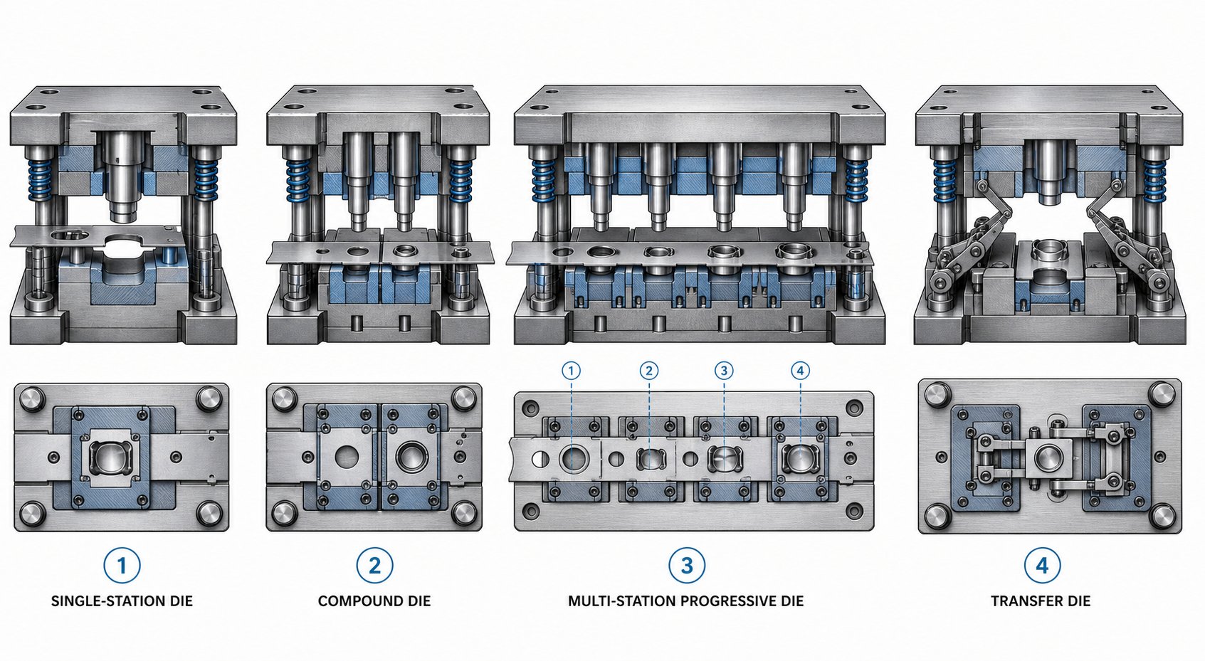
That spectrum from hand stamp to progressive die raises an obvious next question: which type of stamping die fits your project? Picking the wrong one is one of the costliest mistakes buyers make. Choose a die too simple for your part geometry and you'll burn money on secondary operations. Over-engineer the tooling for a modest production run and you'll never recoup the investment. Here's how the four main types of stamping dies break down in practice.
Simple and Compound Dies
Simple dies perform a single operation per press stroke. One stroke, one cut, one bend, or one form. That's it. They're the workhorses of low-volume production and prototyping, where flexibility matters more than speed. Multiple simple dies can be arranged in a tandem press line, with parts loaded manually or by robot between stations. This setup keeps individual tooling costs low, but labor and cycle time add up fast at higher volumes.
Compound dies take the next step by performing multiple cutting operations in a single stroke. Imagine producing a washer: in one press cycle, the compound die simultaneously punches the center hole and blanks the outer diameter. The result is a flat, precise part completed in one hit. Because everything happens at once, compound dies produce flatter parts than progressive alternatives and the tooling is faster and less expensive to build. The trade-off? They're limited to relatively simple, flat geometries. When your part needs bending, deep forming, or complex sequential operations, compound dies can't keep up.
Progressive Dies for High-Volume Production
Progressive dies are where high-volume metal stamping dies truly shine. A coil of sheet metal feeds through a series of sequential stations, each performing a specific operation - cutting, punching, bending, forming - as the strip advances a fixed distance (the pitch) with every press stroke. The workpiece stays connected to a carrier strip throughout the process, and the finished part separates only at the final station.
Production speeds can reach 1,500 parts per minute for small components. Progressive dies often run unattended with coil feeders and straighteners, meaning a single operator can monitor multiple presses simultaneously. The concept of stage tooling is central here: each station in the die represents a discrete manufacturing stage, and the sequencing of those stages determines part quality, material utilization, and cycle time. Poorly sequenced stages create stress concentrations, material thinning, or misfeeds that kill productivity.
The catch? Progressive dies demand high upfront investment and precision engineering. Damage to a single station means pulling the entire die set for repair. They're also unsuitable for deep-drawn parts, since the carrier strip limits how far material can flow.
Transfer Dies and Specialty Configurations
Transfer stamping solves the limitations of progressive dies by separating each part from the metal strip as the very first operation. Mechanical fingers or rails then move individual blanks between independent stations for forming, bending, drawing, or threading. Because no carrier strip restricts material flow, transfer dies excel at producing large, deep-drawn, or geometrically complex components like automotive body panels and tube applications.
Three-axis transfer systems can grip, lift, move, and lower parts into precise positions at each station, enabling operations that would be impossible with a connected strip. The flexibility comes at a cost: transfer dies require sophisticated mechanical and electronic controls, more die protection sensors, and blank destacking systems. Setup times are longer, and maintenance demands increase with mechanical complexity.
For buyers evaluating dies and stamping solutions, the decision between progressive and transfer often comes down to part depth and size. If your component is relatively flat and small, progressive wins on speed and cost-per-part. If it's large, deep, or requires rotation between operations, transfer is typically the only viable path.
| Die Type | Production Volume | Part Complexity | Tooling Cost Range | Typical Cycle Speed |
|---|---|---|---|---|
| Simple (Line) Die | Low to medium | Single operation; simple geometry | $5,000 - $30,000 | 7 - 30 parts/min |
| Compound Die | Medium to high | Flat parts; multi-cut in one stroke | $10,000 - $50,000 | 20 - 60 parts/min |
| Progressive Die | High to very high | Complex multi-operation parts (limited draw depth) | $30,000 - $250,000+ | 50 - 1,500 parts/min |
| Transfer Die | Medium to high | Large, deep-drawn, or intricate 3D parts | $50,000 - $500,000+ | 10 - 40 parts/min |
The right stamping die type isn't always obvious from part geometry alone. Material behavior under forming pressure, required tolerances, and your annual volume targets all factor into the equation. Those material and process mechanics are where the next layer of decision-making gets technical - and where many sourcing mistakes quietly begin.
How the Metal Stamping Process Works Step by Step
Knowing which die type fits your project is only half the picture. The other half is understanding what actually happens to the metal once the press cycles. Many buyers spec tooling without grasping the mechanics underneath, and that blind spot leads to tolerance issues, excessive scrap, and frustrating back-and-forth with die shops. Here's how the metal stamping process works from raw coil to finished part.
A typical stamping cycle follows a repeatable sequence every time the press ram descends:
- Material feeding - coil stock unwinds through a straightener and feeds into the die at a precise pitch distance.
- Clamping/stripping - the stripper plate contacts the sheet, holding it flat against the die surface to prevent lifting or buckling.
- Cutting and forming - the punch descends through the sheet into the die cavity, performing the designated operation (blanking, piercing, bending, drawing, or forming).
- Part/slug separation - cut slugs drop through the die opening; formed parts either remain on the carrier strip or eject via mechanical knockouts or air blasts.
- Ram retraction - the punch withdraws, the stripper holds the sheet down to prevent it from lifting with the punch, and the feeder advances the strip to the next pitch position.
That sequence repeats hundreds or thousands of times per minute depending on press speed, material, and part complexity. Each operation within the die process applies force differently to the sheet metal, and understanding those differences helps you avoid specifying the wrong tooling.
Core Stamping Operations Explained
Every sheet metal stamping part is produced through some combination of five fundamental operations. Think of them as building blocks - a progressive die might chain six or eight of them in sequence, while a simple die performs just one.
Blanking cuts a flat shape out of the sheet. The punched-out piece is your finished part (or a blank for further processing). The remaining skeleton is scrap. Blanking produces precise part outlines and is the starting point for components like washers, brackets, and gear blanks.
Piercing punches holes or cutouts into the sheet. Here, the remaining sheet is your part and the punched-out slugs are scrap. It's the inverse of blanking mechanically, even though both use a punch-and-die shearing action. You'll find piercing in nearly every stamped part that needs fastener holes, ventilation slots, or electrical cutouts.
Bending deforms the sheet along a straight axis to create angles, flanges, or channels. No material is removed. Bend allowance and springback calculations drive how the die is designed, and getting them wrong produces parts that don't meet print dimensions.
Drawing pulls flat sheet metal into a three-dimensional cavity, producing cups, boxes, or enclosures without seams. Deep drawing achieves significant depth without rupture by carefully controlling material flow into the die cavity.
Forming reshapes metal without removing material, encompassing operations like embossing, coining, curling, and flanging. Forming adds structural features or decorative details to an otherwise flat stamped part.
Blanking vs Piercing vs Drawing
The mechanical confusion between blanking and piercing trips up even experienced buyers when reviewing die proposals. Both are punching stamping operations that use identical shearing physics - a punch pushes through the sheet into a die opening. The only difference is which piece you keep.
In blanking, the geometry of the die opening defines your finished part dimensions. In piercing, the geometry of the punch defines the hole size. This distinction directly affects how clearance is applied and which component (punch or die) is held to the nominal dimension.
Drawing is fundamentally different from both. Instead of shearing, the metal pressing process in drawing involves plastic deformation where sheet material flows radially inward over a draw radius and into a cavity. The challenge? Controlling that flow. Too much restraint from the blank holder and the material thins or tears. Too little restraint and wrinkles form as excess material compresses. Factors like blank holder force, draw bead geometry, lubrication, and the number of draw stages required all complicate tooling design. This is why deep-drawn parts often cost significantly more to tool than flat blanked components with comparable outer dimensions.
The Role of Die Clearance
Die clearance is the gap between the cutting edge of the punch and the corresponding edge of the die opening. It's typically expressed as a percentage of material thickness per side. Sounds simple, but incorrect clearance is one of the most common root causes of quality problems and premature tool failure in any stamping manufacturing process.
For most mild steel applications, clearance falls between 5% and 10% of material thickness per side. Harder materials like stainless steel require larger clearance (up to 12-15%), while softer metals like aluminum or brass use tighter clearance. A punch and die clearance calculator factors in material type, thickness, and desired edge quality to recommend a specific gap value.
When clearance is too tight, the punch requires more force to shear through the material, generating excessive heat and accelerating wear on both punch and die. Galling becomes a risk as material welds microscopically to the tool surfaces. When clearance is too large, the metal bends rather than shears cleanly, producing heavy burrs on the cut edge, ragged breakaway zones, and inconsistent part dimensions.
The ideal clearance produces a clean shear zone covering roughly one-third of the material thickness, followed by a controlled fracture zone. You'll see a small, consistent burr (typically under 10% of thickness) - not the heavy, razor-sharp burrs that signal clearance problems. In a well-tuned metal stamping manufacturing process, proper clearance also extends die life dramatically because cutting forces distribute evenly rather than concentrating stress on tool edges.
Material properties, die clearance, and forming mechanics all interact to determine how long your tooling lasts before it needs sharpening or replacement. That durability equation starts with what the die itself is made from - the tool steel grade, its heat treatment, and any surface coatings applied to combat wear.
Die Materials and Tool Steel Selection Guide
A stamping die's geometry determines what shape it produces. The stamping die steel determines how long it keeps producing that shape accurately. Pick the wrong material and you're looking at premature chipping, excessive wear, or catastrophic cracking mid-run - each one meaning unplanned downtime and emergency repair costs. Yet many buyers treat material selection as an afterthought, accepting whatever their die shop defaults to without questioning whether it's optimal for the application.
Tool Steel Grades for Stamping Dies
Tool steel is a family of carbon alloy steels engineered specifically for hardness, abrasion resistance, and the ability to hold shape under repeated stress. Within that family, different grades serve vastly different roles in steel stamping dies. Here's how the major categories break down for metal press dies:
Carbon tool steel (W-series) is the entry point. Water-hardening and relatively inexpensive, these grades work for short-run tooling and prototype dies where volume targets stay below a few thousand parts. They wear fast under production conditions, but their low cost makes them practical for limited-life applications.
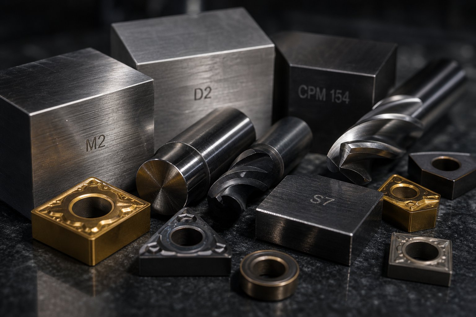
Cold-work tool steels (D2, A2) dominate general-purpose stamping. D2 is a high-carbon, high-chromium grade known for exceptional wear resistance, making it ideal for blanking, punching, and forming dies that require close tolerances. A2 offers air-hardening with better toughness and dimensional stability during heat treatment - a strong choice for punches that see moderate impact loads. When buyers ask about stamping die steel for general production, D2 and A2 cover most scenarios.
Shock-resisting steel (S7) fills a specific niche. Where D2 excels at wear resistance, S7 sacrifices some abrasion performance for high impact toughness. It's the go-to for heavy blanking punches, thick-material shearing, and any station where the tool absorbs significant mechanical shock. As industry practitioners note, the default mindset of "S7 for trim sections, D2 for form sections" persists widely - and while it's a reasonable starting point, it often prevents engineers from exploring better-fit alternatives.
High-speed steel (M2) maintains hardness at elevated temperatures where cold-work grades would soften. In high-speed progressive dies generating significant frictional heat, or in hot stamping applications, M2 retains its cutting edge where D2 would degrade. It achieves approximately 62-64 HRC after tempering and finds common use in cutting tools and high-temperature stamping operations.
Tungsten carbide sits at the extreme end of the durability spectrum. Carbide stamping dies deliver unmatched wear resistance for ultra-high-volume production - millions of cycles on abrasive materials like stainless steel or silicon steel laminations. The trade-off is brittleness and cost. Carbide inserts are typically used selectively at high-wear stations rather than for entire die assemblies, letting engineers target durability precisely where volume demands it most.
For aluminum stamping dies, material selection shifts because aluminum's softness creates different challenges. Galling - where workpiece material welds to the tool surface - becomes the primary failure mode rather than abrasive wear. Polished D2 or A2 with appropriate coatings often outperforms harder grades because surface finish quality matters more than raw hardness when forming aluminum.
Hardness, Toughness, and Wear Resistance Trade-Offs
Here's the uncomfortable truth about stamping die steel: no single grade maximizes all three critical properties simultaneously. Hardness, toughness, and wear resistance exist in tension, and pushing one higher almost always compromises another.
Hardness (measured in Rockwell C scale, or HRC) determines resistance to surface deformation. Higher hardness means the cutting edge holds its geometry longer. D2 reaches 62-64 HRC; A2 hits 63-65 HRC after proper heat treatment.
Toughness measures the ability to absorb impact without fracturing. A tough die bends before it breaks. S7 at 60-62 HRC offers nearly twice the impact resistance of D2 at similar hardness, because its microstructure contains fewer large carbide particles that act as crack initiation sites.
Wear resistance reflects how well the tool surface resists material removal through abrasion or adhesion. Hard chromium carbides in D2 create microscopic armor against abrasive sheet metals, but those same carbides make the steel more prone to chipping under sudden loads.
The practical implication? Around 80% of premature die failures come from fatigue cracking or chipping - not gradual wear. Buyers fixated on maximum hardness often end up with brittle tooling that fractures unexpectedly. The smarter approach is selecting the toughest material that provides sufficient wear resistance for your specific material, thickness, and volume requirements.
Powder metallurgy (PM) steels like CPM 10V represent a modern solution to this trade-off. By atomizing molten steel into fine powder and consolidating it under pressure, manufacturers produce extremely uniform carbide distributions. The result is a material carrying high alloy content for wear resistance while maintaining toughness that conventional steels at the same hardness cannot match. For high-volume progressive dies stamping advanced high-strength steels, PM grades often deliver the lowest total cost of ownership despite material costs running 5-10 times higher than standard D2.
Surface Treatments and Coatings That Extend Die Life
Even with optimal base material selection, surface engineering adds another layer of protection that directly translates to longer intervals between sharpening, less galling, and more consistent stamped steel part quality over the die's service life.
Nitriding diffuses nitrogen into the die surface at relatively low temperatures, creating an extremely hard case (up to 70 HRC equivalent) without distorting the tool's geometry. It's particularly effective on D2 and A2 as a base treatment before applying additional coatings - a technique called duplex coating that enhances adhesion and rigidity support for any subsequent coating layer.
Titanium Nitride (TiN) adds a gold-colored PVD coating that increases surface hardness to approximately 2,300 HV and reduces friction during material flow. It's a cost-effective first step for forming dies processing mild steel and aluminum.
Titanium Carbonitride (TiCN) builds on TiN with higher hardness (around 3,000 HV) and better performance against abrasive materials. For stamped steel components made from stainless or high-strength alloys, TiCN significantly outperforms basic TiN.
Chrome plating provides a thick, low-friction surface ideal for drawing operations. Its self-lubricating properties reduce galling on aluminum and stainless steel draws where adhesive wear dominates.
Diamond-Like Carbon (DLC) coatings deliver extreme hardness and very low friction coefficients. They're increasingly specified for forming operations on advanced high-strength steels where standard coatings break down quickly.
The key insight? Coating decisions aren't independent of substrate material. A premium coating applied to a poorly chosen base steel is money wasted - the softer substrate deforms under load, cracking the rigid coating from beneath. Die shops that treat material selection and surface engineering as a unified system rather than separate line items consistently deliver longer-lasting tooling.
| Die Material | Hardness Range (HRC) | Best Applications | Relative Cost | Expected Die Life |
|---|---|---|---|---|
| Carbon Tool Steel (W1/W2) | 58-65 | Short-run prototyping, low-volume marking dies | Low ($) | 10,000 - 50,000 hits |
| D2 (Cold Work) | 62-64 | Blanking, punching, forming dies; close-tolerance work | Medium ($$) | 250,000 - 1,000,000+ hits |
| A2 (Cold Work) | 63-65 | Blanking punches, trim dies; moderate impact applications | Medium ($$) | 200,000 - 800,000 hits |
| S7 (Shock Resisting) | 60-62 | Heavy blanking, thick material shearing, high-impact punches | Medium ($$) | 150,000 - 500,000 hits |
| M2 (High-Speed) | 62-64 | High-speed progressive dies, elevated temperature operations | Medium-High ($$$) | 500,000 - 2,000,000 hits |
| Tungsten Carbide | 74-78 (HRA equivalent) | Ultra-high-volume production, abrasive materials, laminations | High ($$$$) | 5,000,000+ hits |
| PM Steels (CPM 10V) | 62-65 | High-volume progressive dies, AHSS forming, extreme wear | High ($$$$) | 2,000,000 - 5,000,000+ hits |
Material selection and surface treatment together define how many good parts a die produces before it needs attention. But even the best stamping die steel can't compensate for a flawed design. How the die's geometry, station sequencing, and component architecture come together during engineering is what separates tooling that runs trouble-free from tooling that fights you on every production run.
Die Design Principles and Engineering Fundamentals
A die built from the right steel grade but engineered with flawed geometry, poor station sequencing, or inadequate material flow control will still produce bad parts. Stamping die design is where material science meets mechanical precision, and it's the phase where most preventable tooling failures are born. The engineering decisions made before any steel is cut determine whether a die runs reliably for millions of cycles or becomes a maintenance headache from day one.
CAD/CAM and CAE Simulation in Die Engineering
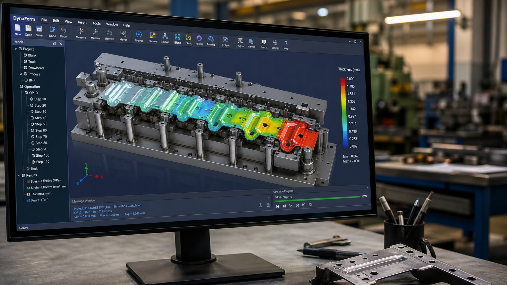
Modern metal stamping die design has moved far beyond hand-sketched layouts and trial-and-error builds. Imagine spending $150,000 on a progressive die only to discover during the first tryout that the material wrinkles at station six or splits during a draw operation. That scenario still happens when shops skip digital validation, but it's entirely preventable.
The current engineering workflow relies on three integrated software categories working in sequence:
CAD (Computer-Aided Design) platforms like SolidWorks, Siemens NX, and CATIA create detailed 3D models of every die component. Specialized add-ins such as Logopress3 and 3DQuickPress automate strip layout creation, unbending calculations, and standard component placement. These tools generate the digital blueprint that downstream systems consume.
CAE (Computer-Aided Engineering) simulation software like AutoForm or DYNAFORM runs finite element analysis on the entire stamping process before a single piece of steel is machined. Engineers can predict material flow, identify potential wrinkling or splitting, calculate springback compensation, and optimize blank shape - all digitally. This virtual tryout step de-risks the project, shortens the physical validation period, and dramatically increases first-time success rates.
CAM (Computer-Aided Manufacturing) software converts validated designs into CNC toolpaths - the G-code that drives mills, lathes, wire EDMs, and grinders to cut actual die components to spec.
Advanced stamping die suppliers integrate all three stages into a continuous digital thread. For example, YICHEN's Stamping Die service covers feasibility analysis and CAE simulation through precision machining, trial runs, and inspection - representing how modern die engineering workflows operate from initial concept to validated production tooling. This end-to-end digital approach means design flaws surface in software, not on the press floor.
Design-for-Manufacturability and Stamping Constraints
Even the most sophisticated simulation can't rescue a part that was never designed with stamping in mind. Design-for-Manufacturability (DFM) is the practice of shaping part geometry around what metal punches and dies can realistically produce - and it's where collaboration between the part designer and the die engineer pays dividends.
Key DFM principles that directly affect stamping design include:
- Bend radii - inside bend radius should be at least equal to material thickness. Sharper bends stress the material and require more aggressive tooling that wears faster.
- Hole placement - holes should sit at least 1.5 times material thickness away from bends, edges, and adjacent holes. Violations distort features and crack material.
- Hole sizing - minimum hole diameter should equal or exceed material thickness. Smaller holes demand fragile punches prone to breakage.
- Tolerances - over-tolerancing non-critical features can exponentially increase die cost. A shift from +/- 0.05mm to +/- 0.005mm may require carbide tooling, optical grinding, and additional in-process inspection.
- Material selection - high-strength steels and exotic alloys introduce springback challenges and accelerate die wear. Designing around a more formable material simplifies tooling significantly.
The strip layout design, particularly for progressive dies, applies these principles across every station. Operations sequence logically: piercing and notching happen early on flat material, while bending and forming occur at later stations after the profile is established. Features like negative and positive bypass notches in sheet metal stamping dies allow the carrier strip to flex around formed features without interference as it advances through the tool. Getting this sequencing wrong causes dimensional drift, material thinning, or outright tool damage.
DFM isn't about limiting creativity - it's about ensuring your part can be produced reliably, economically, and at volume. Engineers who engage their die supplier early in the design process routinely save 15-30% on tooling costs by adjusting non-critical features before anything is committed to steel.
Key Die Components and Their Functions
Every stamping die, from a simple blanking tool to a multi-station progressive die, shares a common structural anatomy. Understanding these metal stamping components helps buyers evaluate proposals, ask informed questions, and spot potential quality gaps in supplier quotes.
- Die shoe (upper and lower) - the foundation plates that mount to the press ram and bed respectively. They hold all other components in alignment and absorb the full tonnage of each press stroke.
- Guide pins and bushings - precision-ground elements mounted in the die shoes that ensure perfect vertical alignment between upper and lower halves. Ball-bearing cages are used in high-precision dies for smoother motion and tighter repeatability.
- Punch plate (punch holder) - a hardened plate attached to the upper die shoe that securely locates and retains all cutting and forming punches in their exact positions.
- Punches - the male working components. Piercing punches cut holes, blanking punches cut part perimeters, and forming punches create bends or draws. Each is custom-shaped to its specific task.
- Die block (die button/insert) - the female counterpart to the punch, containing a cavity shaped precisely to the punch profile plus calculated clearance. High-wear die inserts are often replaceable carbide components.
- Stripper plate - holds the sheet flat during cutting and strips it off retracting punches after each stroke. Spring-loaded strippers also clamp the material to prevent movement during forming.
- Pilots - conical or bullet-nose pins that engage pre-pierced holes to position the strip precisely at each station before any other operation occurs. They correct minor feeding errors and ensure station-to-station accuracy.
- Stock guides and lifters - rails that keep the strip centered as it feeds, and spring-loaded elements that lift the strip off the die surface after forming so it can advance freely.
The interaction of these stamping die components is precisely timed to the press cycle. A misalignment of even a few microns between guide pins can cascade into punch breakage, burr formation, or dimensional drift across the entire production run. This is why qualified die builders validate every component against design intent using coordinate measuring machines and optical inspection before final assembly.
With the engineering and component architecture defined, a practical question emerges: what does all this precision actually cost? Die complexity, material choices, tolerance requirements, and production volume targets all feed into a pricing equation that many buyers find opaque - and where unclear expectations lead to budget surprises.
Cost Factors and Pricing in Die Manufacturing
Tooling quotes in tool & die manufacturing often feel like black boxes. Two suppliers can look at the same part drawing and return prices $30,000 apart. That gap rarely means someone's overcharging - it usually means each shop interpreted your requirements differently, proposed different die types, or assumed different die life targets. Understanding what actually drives cost puts you in a position to compare quotes on equal footing and avoid overpaying for capability you don't need.
What Drives Stamping Die Tooling Costs
Not all cost drivers carry equal weight. Here's what impacts your total tooling price, ranked from highest to lowest influence:
- Die complexity and number of stations - a 12-station progressive die costs exponentially more than a 4-station tool. Every additional station adds design engineering, precision machining, and assembly hours. Complex geometries requiring tight-sequenced forming operations multiply cost quickly.
- Tolerance requirements - jumping from +/- 0.1mm to +/- 0.02mm can double tooling cost. Tighter tolerances demand harder tool steels, wire EDM cutting, optical grinding, and more validation cycles.
- Required die life - a die warranted for 100,000 hits uses different materials and heat treatments than one built for 5,000,000 cycles. Carbide inserts, PM steels, and premium coatings extend life but add substantially to upfront investment.
- Material being stamped - dies processing stainless steel or advanced high-strength steel need harder, more wear-resistant tooling than those stamping mild steel or aluminum. Abrasive workpiece materials accelerate wear, requiring premium die steels.
- Part size and press tonnage - larger parts need larger die shoes, heavier plates, and bigger presses. Material cost for the die itself scales with physical size.
- Secondary features - in-die tapping, in-die assembly, sensors, and automatic inspection add engineering complexity beyond standard cutting and forming operations.
For context, simple blanking dies might run $8,000 to $25,000, while multi-station progressive dies for complex stamping parts range from $30,000 to well over $250,000. High-volume automotive transfer dies can exceed $500,000. Those numbers feel steep until you calculate what they deliver per part over the die's lifetime.
Cost-Per-Part Economics and Break-Even Volume
Here's where the math flips in stamping's favor. A custom metal stamping die is an upfront asset that drives per-part cost toward pennies at volume. Consider a real scenario:
- Custom die investment: $12,000
- Per-part cost with stamping: $0.45
- Per-part cost via CNC machining (no tooling): $3.50
Break-even volume: $12,000 / ($3.50 - $0.45) = roughly 3,900 parts. Below that number, machining your stamped metal parts is cheaper overall. Above it, every additional metal stamped part saves $3.05 compared to the alternative. At 20,000 parts, that $12,000 die adds just $0.60 per piece while CNC machining would have cost $70,000 total - a savings of over $49,000.
The mistake buyers keep making? They evaluate tooling cost based on a single order rather than lifetime volume. If you'll reorder 5,000 units annually for three years, your real volume is 15,000 - well past break-even for most custom metal stampings. Each reorder arrives faster (no new tooling lead time) and cheaper (just per-part price plus setup). Stamping manufacturing economics reward long-term thinking.
Material cost amplifies the advantage further. When metal parts stamping uses expensive alloys like stainless steel or beryllium copper, stamping's superior material utilization (optimized strip layouts waste less) compounds savings with every production run.
How to Evaluate and Compare Die Quotes
When custom metal stamping dies quotes vary wildly, the issue is almost always inconsistent assumptions between suppliers. A detailed cost analysis shows that unit price bundles five underlying drivers: material (45-55%), labor (15-25%), overhead (10-20%), quality assurance (2-8%), and packaging (2-5%). On top of that, per-run setup fees, inspection requirements, and post-processing can add $0.10 to $1.00 per piece if not specified upfront.
To get truly comparable quotes, your RFQ needs to nail down specifics that eliminate guesswork:
- Name exact material standards with traceability requirements - "Q235B per GB/T 700" not just "carbon steel"
- Define tolerance classes numerically - "±0.05mm on critical holes" not "tight tolerances"
- Specify annual volume projections and expected die life in total hits
- Call out surface treatments, plating specs, and packaging standards explicitly
- Request itemized quotes separating tooling cost, per-piece price, setup charges, and any recurring inspection fees
Without those callouts, you'll compare quotes reflecting totally different assumptions about quality level, die life expectancy, and what's included. The lowest tooling price isn't necessarily the best value if it produces a die warranted for 100,000 hits when you need 2,000,000.
Cost clarity helps you invest wisely, but even a perfectly specified die starts degrading the moment it goes into production. How you maintain that investment - and when you recognize it's failing - determines whether your cost-per-part projections hold up over the years or quietly erode as quality drifts.
Die Maintenance, Troubleshooting, and Lifespan
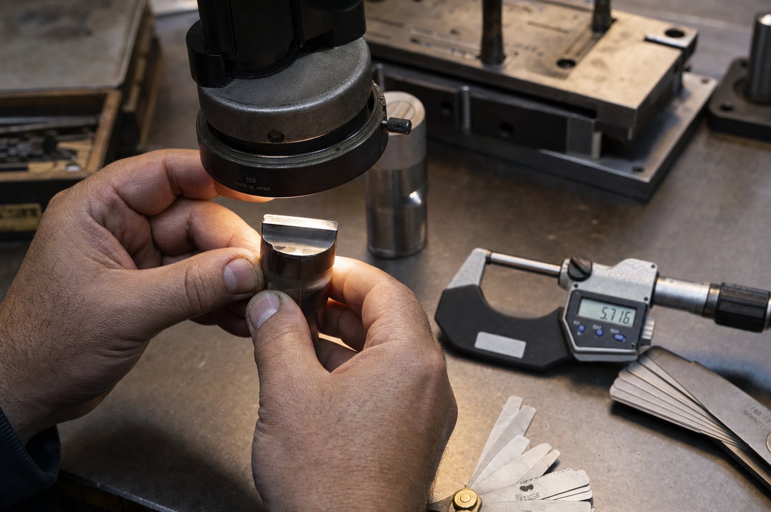
A $100,000 progressive die doesn't fail all at once. It degrades quietly - a slightly taller burr this week, a dimension drifting 0.01mm next month, a surface scratch that wasn't there yesterday. Buyers who invest heavily in metal stamping tooling but neglect structured maintenance routinely lose 30-50% of their die's potential lifespan. The parts keep coming off the die stamping press, but quality erodes so gradually that by the time someone notices, the damage demands expensive repair rather than simple upkeep.
Preventive Maintenance Schedules and Best Practices
Effective stamping tooling maintenance combines time-based checks with stroke-count triggers. A die running 500,000 hits per month needs sharper intervals than one cycling 20,000. Here's how a practical schedule breaks down:
Per shift: check for visible burrs, misfeeds, slug buildup, and abnormal press noise. Confirm lubrication is reaching all contact points. These quick observations catch problems before they cascade.
Weekly: inspect pilots, springs, guide pins, and scrap evacuation paths. Clean trapped fines and dried lubricant from stations that repeatedly accumulate debris.
Monthly or at documented stroke intervals: measure cutting-edge wear, verify punch-to-die clearance with feeler gauges, and review sharpening needs based on actual wear data rather than arbitrary schedules. Replace springs showing more than 10% free-length loss.
Annually: conduct full teardown, metrology review, and cumulative wear assessment. Update PM records and adjust intervals based on what the history shows.
The key principle? Service frequency should follow production reality - material abrasiveness, part criticality, and die complexity - not a generic calendar. A precision die running abrasive stainless steel at high speed needs tighter review cycles than one blanking mild steel at modest volumes.
Diagnosing Die Problems from Part Defects
When quality slips, the stamped part itself tells you where to look. Every defect pattern maps back to a specific die condition. Here's a checklist connecting symptoms to root causes:
- Increasing burr height - worn cutting edges or punch-to-die clearance has opened beyond spec. Sharpening or regrinding restores the condition.
- Galling (material buildup on die surfaces) - tight draw clearances, poor surface finish, or inadequate lubrication. Polish contact areas and verify clearance geometry.
- Chipping or edge breakage - tool steel overload, material mismatch, or a die stamping machine delivering excessive tonnage. Stop production immediately and inspect mating components.
- Dimensional drift - misalignment from worn guide pins, loose mounting hardware, or inconsistent press shut height. Reverify setup before assuming stamping die parts need replacement.
- Surface scratches or score marks - trapped debris, dried lubricant, or worn contact surfaces in the strip path. Thorough cleaning often resolves this without any tool stamping component replacement.
- Misfeeds or strip tracking errors - pilot wear, incorrect feed pitch, or obstructions in the stock path. Check progression-related components first.
- Spring fatigue (weak stripping or inconsistent blank hold) - springs past their service life lose force gradually. Measure free length against spec and replace proactively.
A critical diagnostic principle from experienced tool and die shops: always verify setup and housekeeping before changing tooling. Trapped slugs, loose bolts, and blocked scrap paths mimic wear-related defects but cost nothing to fix. Jumping straight to stamping tool repair without checking the basics wastes time and sometimes introduces new problems.
Repair vs Replace Decision Framework
Every die eventually reaches a point where routine sharpening and component swaps no longer hold a stable process. The question isn't whether that point arrives - it's whether you recognize it before sinking repair dollars into tooling that needs rebuilding.
Keep sharpening when edge wear is uniform, the die returns to spec after regrinding, and part quality stabilizes immediately after service. Normal cutting-edge wear on a well-designed die is a maintenance problem, not a structural one.
Repair or recondition when damage is localized - a cracked punch, a worn guide bushing, a single station losing tolerance. Replacing individual stamping die parts makes sense if the rest of the tool remains dimensionally stable and the failure isn't recurring.
Replace or redesign when you see repeated alignment loss after verified maintenance, chronic dimensional drift that returns within days of service, structural cracking in die shoes or plates, or the same station failing shortly after every repair cycle. At this point, the die's accumulated wear exceeds what component replacement can address.
The deciding factor is pattern recognition. A single failure is an event. The same failure recurring after proper repair is a trend - and trends point to design limitations, material fatigue, or production demands that have outgrown the original tooling specification. Keeping detailed maintenance records (hit counts, defect codes, repair actions, and post-service quality results) transforms this decision from gut instinct into data-driven analysis.
Proper maintenance extends die life by 2-3x compared to run-to-failure approaches, but it also generates the documentation you'll need when it's time to source replacement tooling. That sourcing process - knowing what to specify, what questions to ask, and what a qualified die partner should deliver - is where the next layer of buyer mistakes quietly accumulates.
How to Specify and Source a Custom Stamping Die
Maintenance logs tell you when a die has reached end of life. What happens next - sourcing its replacement or specifying a brand-new tool - is where buyers either streamline the process or repeat every mistake that plagued their original tooling. The difference usually comes down to preparation. A well-structured RFQ gets you accurate, comparable quotes in days. A vague one triggers weeks of clarification emails and quotes built on assumptions you never approved.
What Information Your Die Manufacturer Needs
Every qualified metal stamping die manufacturer needs the same core package before they can quote responsibly. Missing even one element forces the shop to guess - and those guesses get baked into your price, lead time, or worse, your die's performance.
Here's what to prepare before reaching out to stamping die manufacturers:
- Part drawings with GD&T - include full geometric dimensioning and tolerancing callouts. Datum references, positional tolerances, and flatness requirements tell the die engineer which features drive tooling complexity. As sheet metal fabrication experts note, without defined tolerances the manufacturer applies defaults that may not meet your design intent.
- Material specification - call out the exact standard and grade (e.g., "SUS304 per ASTM A240" or "SPCC per JIS G3141"). Different materials require different die steels, clearances, and coatings.
- Annual volume projections - your expected yearly quantities and total lifetime volume determine whether the shop quotes a simple die or a progressive tool with carbide inserts built for millions of cycles.
- Tolerance requirements by feature - identify which dimensions are critical versus general. Over-tolerancing everything inflates tooling cost; under-specifying critical features produces parts that don't assemble.
- Surface finish expectations - specify Ra values or visual standards for cosmetic surfaces. A decorative exterior panel demands polished die surfaces that a hidden structural bracket does not.
- Secondary operations - note any in-die tapping, hardware insertion, or post-stamping processes that affect how the die delivers finished parts.
Critical Questions to Ask Potential Suppliers
A complete RFQ package gets you quotes. The right questions separate capable metal stamping die manufacturers from shops that will struggle with your project. When evaluating any stamping tool and die supplier, dig into process capability rather than just price:
- What CAD/CAM and CAE simulation tools do you use during die design? Shops running forming simulation catch problems digitally rather than discovering them during costly physical tryout.
- What tool steel grades and surface treatments are standard for my material and volume? The answer reveals whether the supplier is engineering for your application or defaulting to one-size-fits-all choices.
- What does your tryout and validation process include? A single hit on the press is not validation. Look for documented T0/T1 sampling, dimensional reporting, and CPK process capability analysis across multiple production cycles.
- How do you handle engineering changes after die approval? Flexibility to accommodate ECNs without full redesign - through idle stations or modular inserts - protects your investment as product designs evolve.
- What is the documented die life expectation, and what warranty covers premature failure?
A qualified metal tool and die partner answers these questions with specifics, not generalities. If the response to "what simulation tools do you use?" is vague, that's a signal the shop relies on trial-and-error approaches that cost you time and money during development.
From RFQ to Production-Ready Tooling
The best stamping dies manufacturer relationships aren't transactional. They follow a structured development path that validates every assumption before committing to production volume. Here's what that path looks like with a full-service partner:
- Feasibility analysis - the supplier reviews your part geometry, material, and tolerances against stamping constraints. They identify potential forming risks, suggest DFM improvements, and confirm the project is viable before quoting detailed tooling.
- CAE simulation and strip layout - forming simulation validates material flow, predicts springback, and optimizes station sequencing. The strip layout locks in material utilization and production logic.
- Die design review and approval - you review and approve the complete 3D die design, including component materials, clearance specifications, and expected die life documentation.
- Precision machining and assembly - CNC milling, wire EDM, grinding, and heat treatment produce die components to spec. Assembly brings everything together with verified alignment.
- Trial runs and T0/T1 sampling - the die runs on a production-class press, producing sample parts measured against your drawing. Adjustments address any springback or dimensional deviations observed in physical tryout.
- Dimensional inspection and validation - CMM measurements, first-article inspection reports, and process capability studies confirm the die meets specification before it ships.
- Production release and ongoing support - the validated die enters your production environment with maintenance documentation, recommended sharpening intervals, and spare component specifications.
This end-to-end workflow is what separates a true metal stamping tool and die partner from a shop that simply delivers a block of machined steel. YICHEN's Stamping Die service exemplifies this full-lifecycle approach - taking sourcing managers and tooling engineers from feasibility and CAE simulation through machining, trial runs, and inspection. That complete coverage means problems surface during development rather than on your production floor, and your custom metal stamping die arrives validated and production-ready rather than requiring additional debugging at your facility.
When evaluating any stamping dies manufacturer, prioritize partners who own the entire process from simulation to validated tooling. A lower quote from a shop that hands you an untested die and disappears will cost more in the long run through extended tryout cycles, engineering changes, and delayed production launches. The costliest mistake in metal stamping tool and die sourcing isn't overpaying for tooling - it's underpaying for capability and inheriting every problem the supplier couldn't solve.
Frequently Asked Questions About Metal Stamp Tool and Die
1. What is the difference between a metal stamp and a stamping die?
A metal stamp is a handheld or machine-operated tool that presses markings like serial numbers or logos into a surface. A stamping die is a custom-engineered precision instrument consisting of a punch and cavity mounted on guided die shoes, designed to cut, bend, draw, or form sheet metal into finished parts at high volume. Both apply force through a shaped instrument, but stamping dies involve significantly more engineering complexity, higher tooling investment, and production capabilities measured in thousands or millions of identical parts per die set.
2. How much does a custom metal stamping die cost?
Custom stamping die costs range widely based on complexity. Simple blanking dies start around $5,000 to $25,000, compound dies run $10,000 to $50,000, progressive dies range from $30,000 to over $250,000, and large transfer dies for automotive applications can exceed $500,000. The primary cost drivers are the number of stations, tolerance requirements, die life expectations, material being stamped, and part size. A full-service supplier like YICHEN (https://www.yichen-group.com/stamping-die/) provides feasibility analysis upfront so buyers understand cost implications before committing to tooling investment.
3. What tool steel is best for stamping dies?
The best tool steel depends on your application. D2 (high-carbon, high-chromium) offers excellent wear resistance for general blanking and forming at 62-64 HRC. A2 provides better toughness with air-hardening stability for moderate-impact punches. S7 handles heavy shock loads in thick-material shearing. M2 high-speed steel maintains hardness at elevated temperatures in high-speed progressive dies. Tungsten carbide delivers maximum wear resistance for ultra-high-volume runs exceeding 5 million hits. Powder metallurgy grades like CPM 10V balance wear resistance and toughness for advanced high-strength steel applications.
4. When should I choose a progressive die over a transfer die?
Choose a progressive die when your parts are relatively flat, small to medium in size, and required in high volumes (50 to 1,500+ parts per minute). Progressive dies keep the workpiece connected to a carrier strip throughout sequential stations, making them ideal for complex multi-operation parts without deep draws. Choose a transfer die when parts are large, require deep drawing, or need rotation between operations. Transfer dies separate each blank first, then mechanical fingers move individual pieces between independent stations, allowing material flow that a connected strip cannot accommodate.
5. How do I know when a stamping die needs repair or replacement?
Monitor part quality indicators: increasing burr height signals worn cutting edges, dimensional drift suggests guide pin wear or misalignment, and galling indicates clearance or lubrication problems. Keep sharpening when edge wear is uniform and quality stabilizes after service. Repair when damage is localized to a single component like a cracked punch or worn bushing. Replace or redesign when you see repeated alignment loss after verified maintenance, chronic dimensional drift returning within days of service, structural cracking in die shoes, or the same station failing repeatedly after proper repair. Detailed maintenance records with hit counts and defect codes transform this decision from guesswork into data-driven analysis.


