


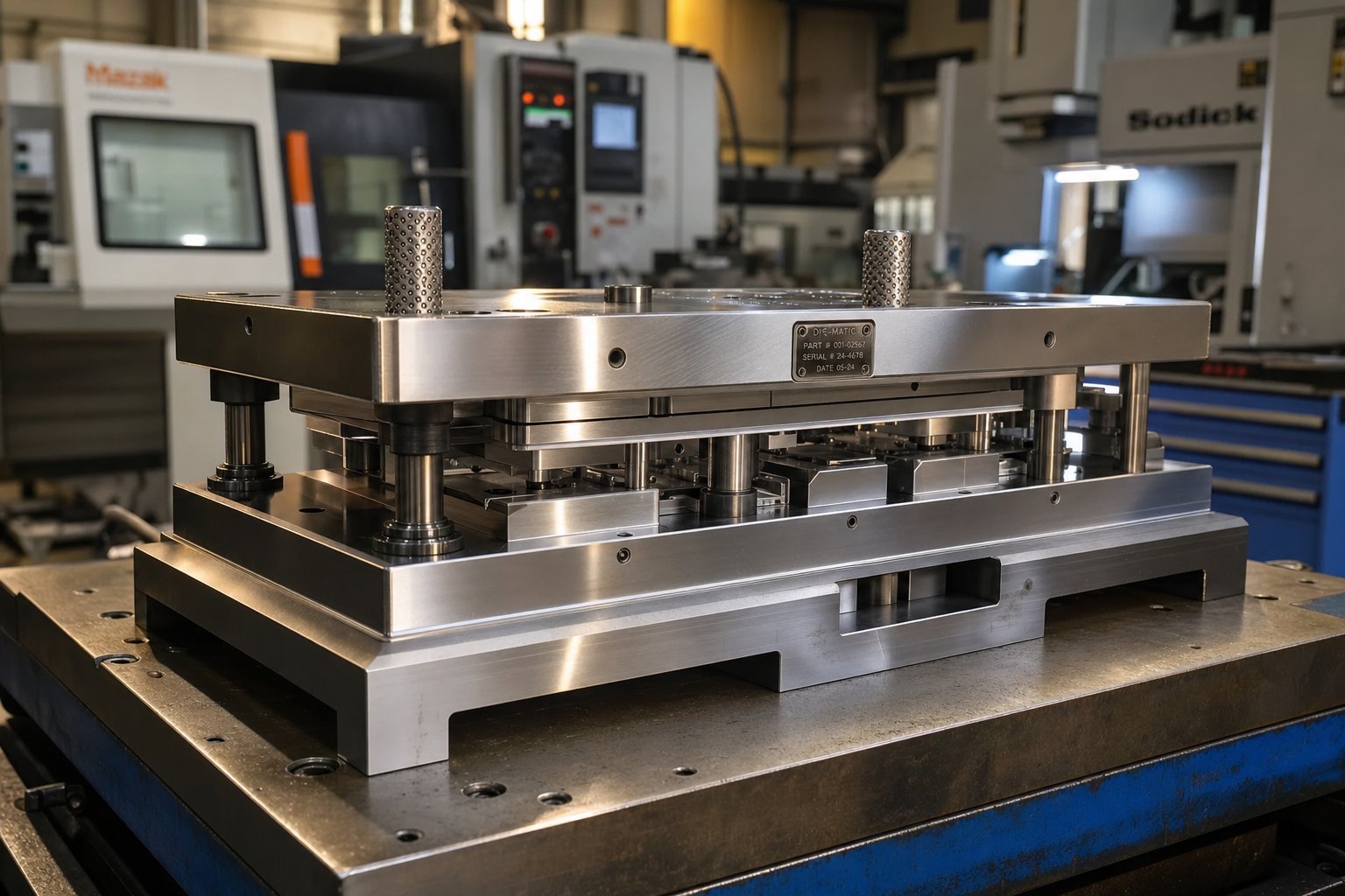
What a Stamping Die Maker Actually Does
When you hear the term "stamping die maker," it can refer to two things: a skilled tradesperson who builds and maintains stamping dies, or the specialized shop that employs them. Either way, the work involves transforming raw tool steel into precision instruments capable of shaping metal parts at production speed. It is a trade that sits squarely at the intersection of engineering, metallurgy, and high-precision machining.
A stamping die maker is a specialist who interprets engineering drawings, designs die geometry, programs CNC machines, assembles hardened steel components, and validates finished tooling through tryout press runs to produce stamping dies that cut, form, and shape sheet metal with repeatable accuracy.
Defining the Stamping Die Maker Role
The scope of this role stretches far beyond running a machine. A die maker reads and interprets blueprints, CAD files, and dimensional specifications to understand the exact part geometry required. From there, they compute tolerances, plan machining sequences, and determine how each stamping die will perform under press loads. According to the U.S. Bureau of Labor Statistics, tool and die makers construct precision tools or metal forms used to cut, shape, and mold metal, plastics, and other materials.
Responsibilities span the full lifecycle: from initial tool and die design concepts through CNC programming, component fitting, surface finishing, and final test runs. When a completed die stamps its first part on a tryout press, the die maker inspects for defects, measures dimensional accuracy, and adjusts until everything meets specification. In Ontario, Canada, apprenticeship programs for this trade require approximately 8,000 hours of combined on-the-job and classroom training, reflecting the depth of expertise involved.
Skills That Set Die Makers Apart
What separates a capable die maker from a general machinist is the combination of analytical reasoning, manual dexterity, and deep material knowledge working together under tight tolerances, sometimes within 0.0001 of an inch. Precision die and stamping work demands proficiency across multiple disciplines simultaneously. You will find that the best practitioners blend digital fluency with hands-on instinct, adjusting a die stamps fit by feel after verifying it with measurement instruments.
Core competencies include:
- Die design and strip layout development
- CNC programming and multi-axis machining
- Wire and sinker EDM operation
- Surface grinding to mirror-finish tolerances
- Heat treatment knowledge for hardening and tempering tool steels
- Press setup, tryout, and production validation
These skills do not exist in isolation. Every stamping die presents a unique puzzle where part geometry, material behavior, and production volume all influence how the tool must be built. That interplay between die type and application is what ultimately determines whether a project calls for a simple single-station tool or a complex multi-station progressive die.
Types of Stamping Dies and When to Use Each
Knowing the types of stamping dies available is one thing. Understanding which type fits your specific part, budget, and production target is what actually saves you money. Most sourcing engineers encounter die type recommendations from their stamping die maker without a clear explanation of why one approach beats another. Here is the selection rationale that rarely gets spelled out.
Progressive Dies for High-Volume Runs
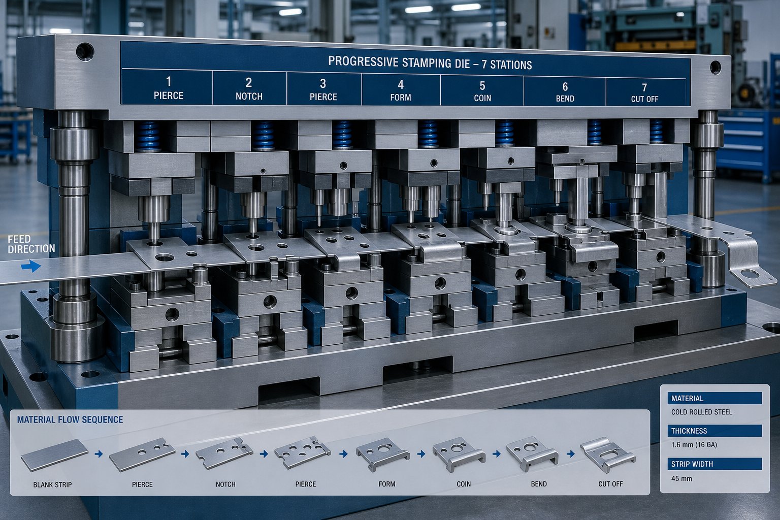
Imagine a coil of sheet metal feeding continuously through a die with multiple stations, each one performing a different cut, bend, or form. That is progressive stamping die design in action. The workpiece stays attached to a carrier strip from start to finish, moving station by station until a completed part separates at the end. This architecture enables cycle times measured in strokes per minute rather than parts per hour, making it the standard choice for automotive stamping dies, electrical metal stamping connectors, and any component produced in the hundreds of thousands annually.
The tradeoff? Higher upfront tooling cost and longer design timelines. Progressive dies demand meticulous strip layout engineering and precision machining across every station. But when volume justifies the investment, per-piece cost drops dramatically, and repeatability stays tight over millions of cycles.
Transfer and Compound Dies
Larger parts that cannot remain attached to a carrier strip need a different approach. Transfer dies separate the blank first, then mechanical fingers move the individual workpiece through independent forming stations. This makes transfer tooling ideal for deep-drawn housings, structural brackets, and components too wide or too deep for progressive strip feeding. Die stamping with transfer systems handles complex 3D geometries that would otherwise require multiple standalone operations.
Compound dies occupy the opposite end of the complexity spectrum. They execute multiple operations, cutting, punching, and sometimes forming, in a single press stroke. Think flat washers, simple shims, or lamination stacks. The result is high flatness, excellent concentricity between features, and moderate tooling cost. For simple part geometry at medium volumes, compound dies often deliver the best balance of speed and economy.
Single-Station and Specialty Dies
Not every project demands multi-station tooling. Draw dies, blanking dies, piercing dies, and combination dies handle lower-volume or specialized stamping applications where flexibility matters more than cycle speed. A blanking die punches flat profiles from sheet stock. A draw die stretches material into cup or shell shapes. These single-station metal stamping dies cost less to build and are faster to modify when designs evolve, making them practical for prototype runs or niche production.
| Die Type | Best For | Typical Volume Range | Relative Cost | Complexity Level |
|---|---|---|---|---|
| Progressive | Small to mid-size parts with complex features | 100,000+ annually | High | High |
| Transfer | Large or deep-drawn parts | 25,000 - 500,000+ | High | High |
| Compound | Flat parts with multiple features in one plane | 10,000 - 200,000 | Medium | Low to Medium |
| Blanking | Simple flat profiles | 5,000 - 100,000 | Low | Low |
| Draw | Cup, shell, or enclosure shapes | 5,000 - 100,000 | Medium | Medium |
Choosing the right type comes down to a handful of practical criteria that you should evaluate before requesting quotes:
- Part size and maximum envelope dimensions
- Annual production volume and expected tool life
- Tolerance requirements and feature complexity
- Material type and sheet thickness
Getting the dies and stamping approach right at this stage prevents expensive redesigns later. The selection you make here also dictates what materials your die maker will need to work with, which tool steel grades apply, and how long the tooling will last under production loads.
The Die Making Process from Concept to Production Release
Selecting the right die type is just the starting point. What happens between that initial decision and a production-ready tool involves months of engineering, precision machining, and iterative validation. Most buyers never see this process laid out in full, which makes it harder to plan budgets, set realistic timelines, or know when their input is needed. Here is how tool & die manufacturing actually unfolds, stage by stage.
- Concept review and feasibility assessment
- Strip layout development
- Detail die design
- CNC machining of stamping die parts
- Component assembly and fitting
- Heat treatment and surface hardening
- Tryout press runs
- Correction and debugging
- Production sign-off
Each milestone represents a decision gate where the die maker, and often the customer, confirms readiness before moving forward. Skipping or rushing any stage tends to compound problems downstream.
Feasibility Analysis and Die Design
Before any steel gets cut, a stamping die maker evaluates whether the part can actually be formed as drawn. This feasibility phase involves analyzing part geometry, wall angles, draw depths, and material stretch limits. Engineers use FEA-based forming simulation, sometimes called CAE analysis, to predict how sheet metal will behave inside the die. These simulations flag issues like excessive thinning, wrinkling tendency, or springback before a single tool steel block is ordered.
Research in stamping simulation optimization confirms that finite element methods can predict forming defects such as tearing and wrinkling by analyzing strain distribution, thickness variation, and forming limits during virtual tryouts. This kind of upfront analysis shortens development cycles and reduces costly rework.
With feasibility confirmed, the stamping die design phase begins. Engineers develop a strip layout that defines how the flat blank feeds through each station, how material utilization is maximized, and where scrap is generated. Die architecture, including plate sizing, guide systems, and station sequencing, gets finalized in CAD. This is where the die concept becomes a buildable plan.
Machining, Assembly, and Heat Treatment
Turning that design into physical tooling demands precision at every step. CNC milling cuts die blocks and punch profiles to near-net shape. Wire EDM handles intricate contours and tight internal clearances that conventional milling cannot reach. Surface grinding brings critical mating surfaces to flatness tolerances measured in microns.
Once individual stamping die parts are machined, assembly begins. Die makers fit punches into retainers, align cutting edges, set shut heights, and verify that every component moves as intended. This fitting process relies heavily on hands-on skill, as even a few thousandths of an inch of misalignment can cause premature wear or part defects.
Heat treatment follows assembly of the critical wear components. Hardening and tempering processes raise tool steel hardness to required levels, typically between 58 and 62 HRC for cutting edges. The sequence matters: machining happens before hardening because fully hardened steel is far more difficult and expensive to cut. After heat treatment, finish grinding restores precise dimensions that may shift slightly during the hardening cycle.
Tryout, Debugging, and Production Release
With the die assembled and hardened, it moves to a tryout press. This is where theory meets reality. The die maker runs sample parts, inspects them for splitting, wrinkling, dimensional deviation, and surface defects, then traces each issue back to its root cause. Keysight's analysis of virtual die tryouts notes that defects emerging during first trials are both time-consuming and costly to correct, which is precisely why upfront simulation has become standard in stamping tool and die shops.
Debugging custom metal stamping dies is rarely a single-pass process. Springback may require compensation adjustments. Splitting might call for revised draw radii or additional forming stations. Wrinkling could demand blank holder pressure tuning or geometry modifications. Each correction is followed by another tryout run until parts consistently meet print specifications.
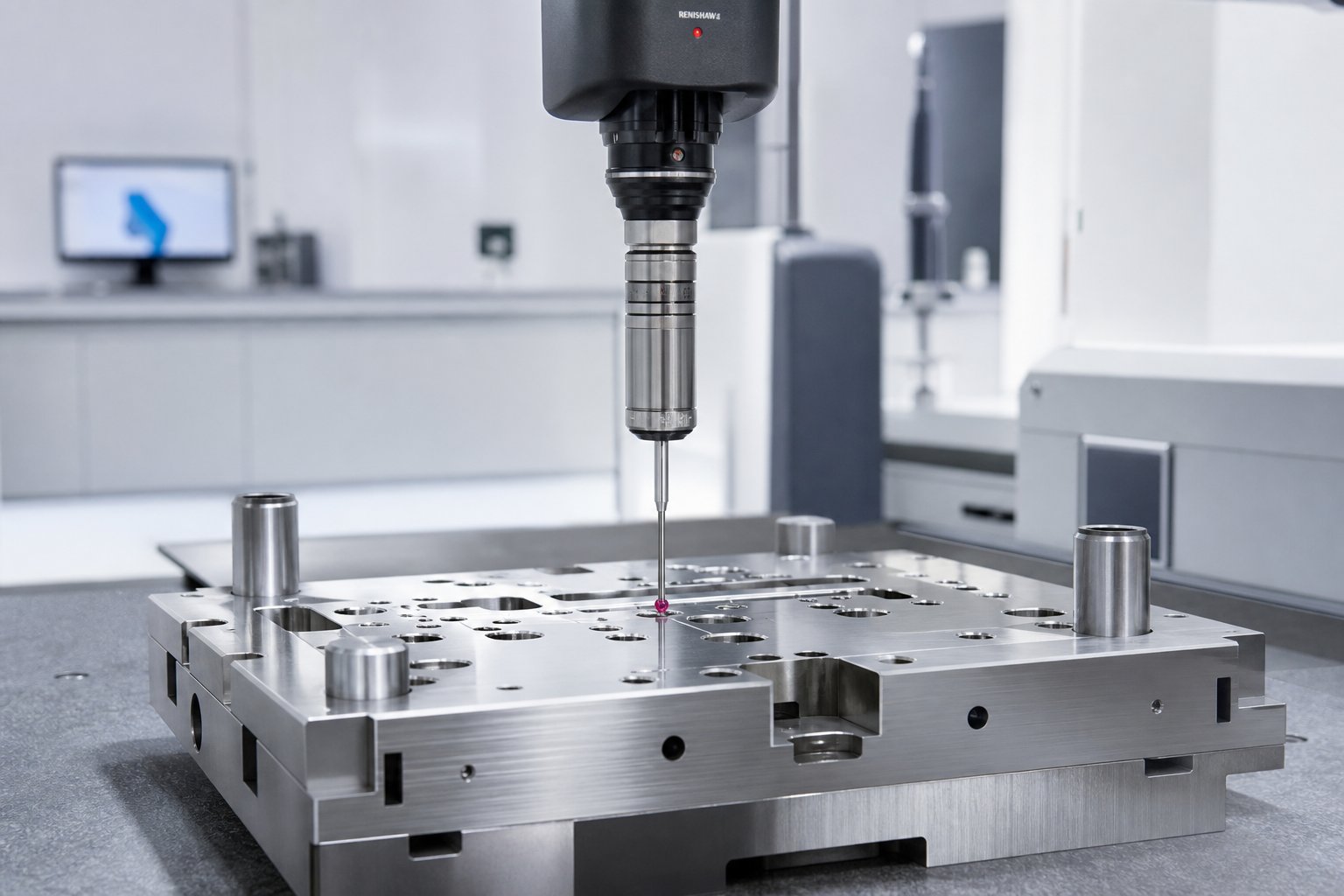
Production sign-off happens when dimensional inspection, often via CMM, confirms that parts fall within tolerance across a statistically meaningful sample. At that point, the dies manufacturing phase is complete, and the tool transfers to the production floor.
This entire sequence, from feasibility through sign-off, is also where the biggest cost and timeline variables hide. Understanding what drives those variables gives buyers far more leverage in planning and negotiation.
Die Material Selection and Tool Steel Grades
The steel inside your die determines how long it lasts, how often it needs maintenance, and ultimately what each stamped part costs you over a production run. Yet material selection is one of the least discussed topics between buyers and their stamping die maker. Most quotes list a grade like "D2" without explaining why that grade was chosen or what alternatives might serve you better. Here is what drives that decision.
Common Tool Steel Grades for Stamping Dies
Every metal stamping die balances three competing properties: hardness for shape retention under load, wear resistance for longevity, and toughness to absorb impact without cracking. No single stamping die steel maximizes all three, so grade selection always involves tradeoffs mapped to your specific application.
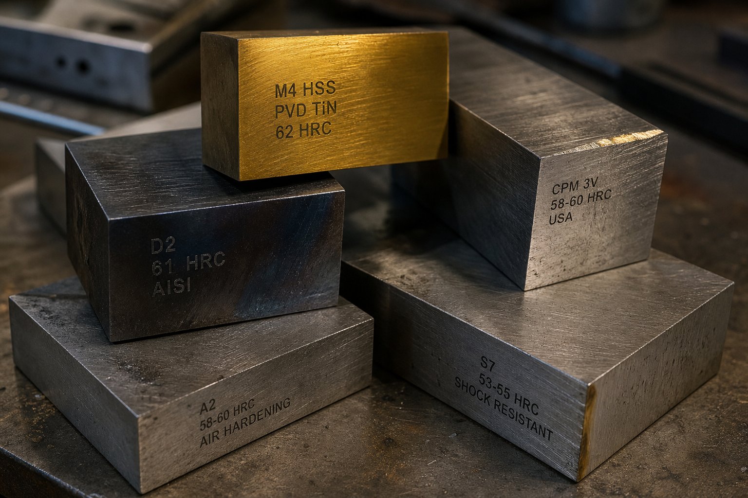
D2 is the workhorse of high-volume blanking and piercing. Its high carbon and chromium content (1.40-1.60% C, 11.00-13.00% Cr) delivers exceptional wear resistance at 54-61 HRC. D2 is commonly used in blanking dies, stamping dies, slitters, and trim dies where exceptional toughness is not the primary requirement. For long-run steel stamping dies producing hundreds of thousands of parts, D2 remains the default choice.
A2 offers a middle ground. With slightly less chromium (4.75-5.50%) and carbon (0.95-1.05%) than D2, it achieves 57-62 HRC while retaining moderate toughness. A2 works well in forming applications, coining, and large blanking dies where the tool encounters bending stresses alongside wear. Think of it as the balanced option for sheet metal stamping dies that must both cut and shape material.
S7 sits at the toughness end of the spectrum. Its lower carbon content (0.45-0.55%) and reduced chromium (3.00-3.50%) yield a working hardness of 48-58 HRC with excellent shock resistance. S7 is the go-to for heavy-gauge forming, cold bending dies, and metal press dies subject to sudden impact loads. If your die is cracking rather than wearing, S7 addresses the root cause.
M2 and M4 high-speed steels serve operations where elevated temperature and speed push conventional cold-work steels past their limits. These grades retain hardness at higher operating temperatures, making them suitable for high-stroke-rate applications.
For extreme-wear stations, particularly in progressive dies running abrasive stainless or high-strength materials, carbide inserts provide a step-change in longevity. Carbide stamping dies or carbide-inserted stations can extend life by 500-1000% compared to conventional tool steels, though their brittleness limits use to low-impact operations like fine blanking and shallow drawing. Aluminum stamping dies, by contrast, often prioritize surface finish and galling resistance over raw hardness, since softer workpiece materials tend to adhere to tooling surfaces rather than wear them down.
| Grade | Hardness (HRC) | Primary Use Case | Relative Cost | Expected Die Life |
|---|---|---|---|---|
| D2 | 54 - 61 | High-volume blanking and piercing | Low to Medium | Longest among conventional steels |
| A2 | 57 - 62 | Forming, coining, and balanced applications | Low to Medium | Moderate to Long |
| S7 | 48 - 58 | Heavy-gauge forming and shock-loaded dies | Medium | Moderate (wear-limited) |
| M2/M4 | 60 - 65 | High-speed and elevated-temperature operations | Medium to High | Long in appropriate applications |
| Carbide | 70+ | Extreme-wear inserts for abrasive materials | High | Significantly longer than tool steels |
The right grade depends on three factors working together: your production volume, the workpiece material being stamped, and the tolerance demands of the finished part. A die maker who selects material without asking detailed questions about all three is guessing rather than engineering.
Surface Treatments and Coatings
Even the best stamping die steel benefits from surface enhancement. Coatings and treatments add a harder, lower-friction layer that reduces galling, slows wear progression, and extends intervals between maintenance shutdowns.
Common coating options include:
- TiN (Titanium Nitride) - a general-purpose PVD coating that increases surface hardness and reduces friction
- TiCN (Titanium Carbonitride) - harder than TiN with better wear resistance for cutting and piercing stations
- TD (Toyota Diffusion / Thermo-Reactive Deposition) - a CVD-family process that creates an extremely hard vanadium carbide layer, effective against galling in high-strength steel forming
- TiAlN (Titanium Aluminum Nitride) - performs well at elevated temperatures generated during high-speed stamping
Research from the AHSS Application Guidelines demonstrates the practical difference coatings make: a chrome-plated D2 tool failed after 50,000 parts, while the same tool steel with ion nitriding and a PVD chromium nitride coating produced over 1.2 million parts. That is not a marginal improvement. It is a fundamentally different cost-per-part equation.
Nitriding, both gas and plasma (ion) varieties, creates a hardened surface layer by diffusing nitrogen into the steel. Ion nitriding runs at lower temperatures than gas nitriding, reducing distortion risk while building a wear-resistant surface. Chrome plating, once a standard approach, has fallen out of favor due to microcracking tendencies and environmental concerns. Studies show it is not the best option for dies processing advanced high-strength steels.
One practical note: coatings should be applied after initial tryout and debugging are complete. Adjusting die geometry after coating means you remove the very layer you just paid for. Experienced die shops complete all corrections first, then apply the final surface treatment before production release.
Material and coating choices cascade directly into project cost and timeline. A die built from powder metallurgy steel with PVD coating costs more upfront than a standard D2 die, but that investment changes the maintenance math entirely over a multi-year production run.
Modern Technologies Reshaping the Trade
Steel grade and coating selection are engineering decisions rooted in decades of metallurgical knowledge. But the way a stamping die maker applies that knowledge, from initial design validation through shop floor execution, has shifted dramatically. Digital tools and advanced machining platforms are compressing timelines, eliminating guesswork, and raising the floor on what a capable die shop can deliver.
CAE Simulation and Digital Prototyping
The biggest leap in die tooling design over the past decade is not a new machine. It is the ability to stamp a part virtually before any steel gets cut. FEA-based forming simulation lets engineers digitally replicate the entire sheet metal forming process: deep drawing, stretch forming, flanging, and trimming. The software maps stress distribution, predicts thickness variation, flags wrinkling zones, and calculates springback deformation, all within hours rather than weeks on a tryout press.
What does this mean practically? According to industry data from CAE simulation specialists, manufacturers who integrate simulation into their tooling design services workflow typically reduce tryout iterations by 30-50%. That translates directly into shorter lead times and lower modification costs. Forming Limit Diagram analysis identifies crack-risk zones and compression-driven wrinkling before machining begins, allowing engineers to adjust blank shape, binder pressure, and draw bead geometry while changes are still free to make.
Springback compensation alone justifies simulation investment for many projects. Rather than discovering that a formed panel springs out of tolerance after the die is hardened, engineers pre-compensate the tool surface geometry digitally. The result is a die that produces dimensionally correct parts from the first production run.
High-Speed Machining and Automation
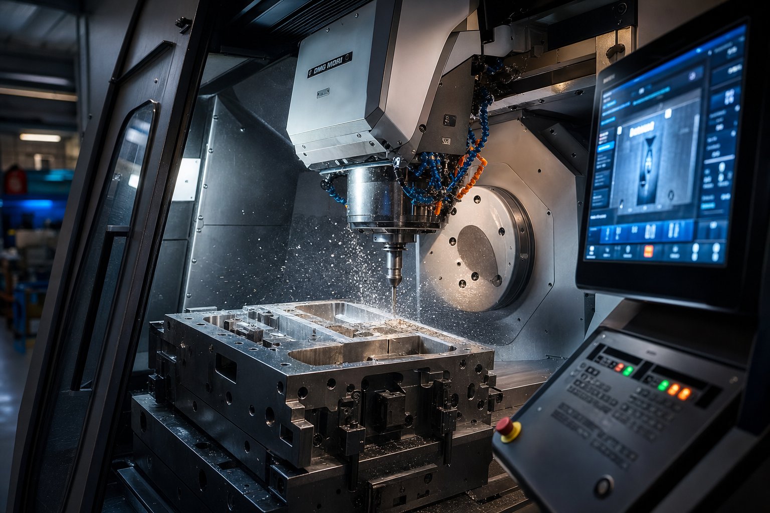
On the shop floor, 5-axis high-speed machining has redefined what is possible in die block cutting. Traditional 3-axis CNC required multiple setups and extensive hand finishing. Modern 5-axis systems machine complex die faces in a single clamping, maintaining optimal tool angles throughout the cut. This produces superior surface finishes directly off the machine, reducing or eliminating manual polishing time.
Automation tool & die shops now deploy automated wire EDM cells that run unattended overnight, loading and indexing workpieces without operator intervention. Robotic polishing systems deliver consistent surface finishes across large die faces where hand polishing would introduce variability. The tooling dynamics here differ from automation on the stamping production floor. In the die shop, automation targets precision and repeatability on one-off tooling. In production, it targets throughput on identical parts.
The combined effect of 5-axis HSM and automated secondary processes is measurable: metal stamping tooling that once required 12-16 weeks of machining time can often ship in 8-10 weeks without sacrificing accuracy.
Digital Twins and Data-Driven Maintenance
An emerging frontier in stamping tooling involves embedding sensors directly into the die itself. These instrumented tools track stroke counts, tonnage per cycle, temperature fluctuations, and dimensional drift in real time. A case study from an automotive stamping facility running 12 high-speed presses found that 68% of unplanned stoppages could have been prevented with 4 to 48 hours of advance warning, using data already available in press sensors and part inspection systems.
Digital twin platforms correlate these signals across presses and die sets, predicting wear progression and scheduling maintenance before defects appear. Progressive die wear patterns become visible in part quality metrics three days before catastrophic tool failure. Facilities deploying these systems report prediction accuracy reaching 85-92% within six months of deployment.
For buyers, this means a die built with in-die sensing capability costs more upfront but delivers lower lifetime cost through fewer surprise shutdowns and extended useful life.
Technologies reshaping the stamping die maker trade today:
- 3D forming simulation with Forming Limit Diagram analysis
- Topology-optimized die structures for weight and rigidity
- High-speed 5-axis CNC machining
- Automated wire EDM cells with unattended operation
- In-die sensing for force, temperature, and stroke monitoring
- Digital twin platforms for predictive maintenance and die life tracking
These capabilities are not evenly distributed across the industry. Some shops operate at the cutting edge while others rely on methods unchanged in decades. That gap creates real differences in what a die project costs, how long it takes, and how the finished tool performs once it reaches your press floor.
Cost Factors and Lead Times for Die Projects
The technology gap between die shops directly shapes two variables buyers care about most: what the tool costs and when it arrives. Yet cost and lead time remain the most opaque aspects of working with a stamping die maker. Quotes vary wildly from shop to shop, timelines stretch without clear explanation, and the factors behind each number rarely get shared with the customer. That lack of transparency does not mean the math is unknowable. It means the framework has never been laid out clearly enough for buyers to ask the right questions.
What Drives Stamping Die Cost
Every custom metal stamping die quote is a composite of decisions, some made by you, some by the die maker, and some dictated by physics. Understanding which variables carry the most weight gives you leverage to optimize cost before the first purchase order is issued.
The single largest cost driver is die complexity, specifically the number of stations and the operations performed at each one. Industry cost estimation data indicates that each additional station in a progressive die increases total cost by roughly 8-12% due to added design time, machining hours, and assembly labor. A five-station blanking and piercing die is a fundamentally different investment than a twelve-station progressive tool with forming, cam actions, and in-die tapping.
Part size matters because it determines the physical scale of the die set, which cascades into material cost, machining time, and the tonnage class of press required for tryout. A die that fits inside a 200-ton press uses less tool steel and runs on more widely available equipment than one requiring a 600-ton machine.
Here are the primary cost drivers, listed in descending order of typical impact on a custom metal stamping tool quote:
- Die complexity - number of stations, cam actions, in-die tapping, lifter mechanisms, and special features
- Part geometry and tolerances - tighter tolerances push machining from standard CNC into precision EDM and jig grinding, which carries significantly higher hourly rates
- Tool steel grade and hardening - premium grades like M4 or carbide-inserted stations cost multiples of standard D2, and heat treatment adds both cost and scheduling time
- Part size and die envelope - larger dies require more raw material, longer machining cycles, and heavier handling equipment
- Annual production volume - high-volume programs justify Class A tooling with premium construction, while lower volumes can use lighter-duty builds
- Surface treatments and coatings - PVD coatings, TD treatment, or nitriding add to the upfront price but reduce per-part cost through extended die life
- Design and simulation scope - full CAE forming analysis and DFM reviews add engineering hours but frequently reduce total project cost by catching problems before machining begins
Tooling class further influences the equation. Class A dies, designed for production runs often exceeding one million strokes, use hardened premium steels and are built for easy maintenance access. The initial investment is higher, but the per-piece amortization drops sharply at volume. Class C or "soft" tooling suits prototypes and short runs under 10,000 parts, trading durability for speed and lower upfront cost. Matching the tooling class to your actual volume requirements is one of the most effective ways to right-size your custom metal die investment.
Die investment and part unit cost are inversely linked over production life. A higher-quality die reduces per-piece cost, minimizes unplanned downtime, and lowers total cost of ownership - making the upfront number far less meaningful than the lifetime number.
One frequently overlooked variable is how much your own design contributes to cost. Tolerances that are tighter than functional requirements demand, unnecessary features that add forming stations, or material choices that accelerate die wear all inflate the quote. Engaging your die maker in Design for Manufacturability discussions before finalizing part geometry can strip cost from the tool without compromising part performance. Custom precision stamping projects benefit enormously from this collaborative approach, because geometry adjustments that seem minor on a CAD screen can eliminate entire die stations.
Typical Lead Time Factors
Timelines frustrate buyers more than cost, partly because the variables are less intuitive. A custom metal stamp die does not simply move through a linear queue. Multiple parallel and sequential processes compete for resources, and bottlenecks shift depending on shop capacity, material availability, and the number of design iterations required.
The most common lead time factors include:
- Design revision cycles - every round of design changes resets engineering hours and may require updated simulation runs; three revision cycles can add weeks to a project that would otherwise flow smoothly
- Material procurement - standard tool steels like D2 and A2 are typically available within days, but specialty grades, large die blocks, or imported alloys can add weeks to the schedule
- Machining complexity - a die with intricate 3D surfaces, tight internal clearances, and multiple cam mechanisms simply requires more hours on CNC and EDM machines than a flat blanking tool
- Heat treatment scheduling - commercial heat treat facilities operate on their own timelines, and large or complex die sections may require multiple treatment cycles
- Tryout iterations - first-article stamping runs rarely produce perfect parts immediately; each correction-and-retrial cycle adds time, and complex forming operations may need several rounds of debugging
- Inspection and documentation - programs requiring PPAP documentation, CMM reports, or customer witness tryouts build additional steps into the release process
Here is a counterintuitive truth that experienced tooling engineers understand: rushing the design phase almost always extends overall lead time. When engineering shortcuts leave ambiguities in strip layout or station sequencing, those gaps surface during machining as rework, during assembly as fit problems, or during tryout as part defects. Each of those downstream corrections costs more time than the design hours that were saved. Custom metal stampings produced from well-engineered dies reach production faster than those built from rushed designs, even when the initial engineering phase runs longer.
Shop capacity is another variable buyers rarely see. A custom metal die stamp project quoted at ten weeks assumes available machine time and skilled labor at each stage. If the shop is running at full capacity, scheduling gaps between machining, EDM, and assembly can stretch the calendar without adding productive hours. Asking about current backlog and scheduling methodology during the quoting stage gives you better visibility into whether a stated timeline is realistic.
The most productive conversations with your stamping die maker happen when you arrive with a clear understanding of these cost and timeline drivers. You do not need to know exact dollar figures or week counts in advance. You need to know which levers you control, which ones the shop controls, and where collaboration between both sides compresses the schedule and brings down the total investment. That foundation also makes it far easier to distinguish capable partners from shops that simply tell you what you want to hear.
How to Evaluate a Stamping Die Maker
Knowing what drives cost and lead time is only useful if you can distinguish between stamping die manufacturers who will deliver on their promises and those who will not. The evaluation process matters because a die project gone wrong does not just waste tooling dollars. It delays your product launch, strains your production schedule, and forces expensive mid-stream corrections. Whether you are vetting a local shop or reviewing proposals from overseas metal stamping die manufacturers, the signals that separate reliable partners from risky ones are remarkably consistent.
Warning Signs That Signal Risk
Some red flags show up in the quoting stage. Others only become visible once you ask the right follow-up questions. If a stamping dies manufacturer exhibits several of these characteristics, treat them as cumulative risk indicators rather than isolated quirks.
- No in-house design capability - a shop that outsources die engineering loses control over the most critical phase of the project and introduces communication gaps between designer and builder
- Inability to show tryout data - if they cannot produce sample parts, dimensional reports, or press tonnage records from previous projects, their process lacks documentation discipline
- No CMM inspection equipment - without coordinate measuring capability, dimensional validation relies on surface plates and hand gauges, which are insufficient for tight-tolerance work
- Missing material certifications - reputable die shops provide mill certs for tool steel and can trace every block back to its source; absence of this practice signals a corner-cutting culture
- Unwillingness to discuss die maintenance - a die manufacturer that avoids the topic of ongoing support, spare components, or maintenance documentation is likely building tools they do not intend to stand behind
- Quoting without reviewing part geometry - any shop willing to give you a firm number based on a verbal description or a 2D sketch is estimating, not engineering
Pay attention to how quickly a shop says yes. The best metal stamping die manufacturers push back on geometry that will cause production problems. Shops that accept everything without questions tend to discover issues later, on your timeline and your budget.
Indicators of a Capable Partner
Green flags point toward a stamping die factory that treats your project as an engineering challenge rather than a transaction. These indicators correlate strongly with on-time delivery, first-tryout success, and long-term die performance.
- Full in-house CAE simulation - forming analysis, springback prediction, and thinning studies done before machining begins, reducing tryout iterations significantly
- Documented tryout methodology - clear procedures for sample runs, defect classification, root cause analysis, and corrective action tracking
- Transparent milestone reporting - regular project updates with photos, machining progress, and schedule forecasts rather than silence between order and delivery
- Vertically integrated machining - CNC milling, wire EDM, surface grinding, and heat treatment managed under one roof, eliminating hand-off delays between subcontractors
- End-to-end process ownership - the shop takes responsibility from initial feasibility review through final inspection and production release
- Willingness to support the die through production life - including maintenance planning, spare part provisioning, and engineering changes as part volumes evolve
A metal stamping dies manufacturer demonstrating these qualities operates as a development partner, not just a vendor filling a purchase order. For example, YICHEN's stamping die operation illustrates this full-service model in practice: their workflow spans feasibility assessment and CAE simulation through precision machining, trial runs, and dimensional inspection, all managed internally. That kind of vertical integration gives buyers a single point of accountability and eliminates the coordination risk that comes with fragmented supply chains.
When comparing proposals from multiple stamping die manufacturers, weight these qualitative indicators as heavily as price. A lower quote from a shop missing half the green flags above typically costs more in total once you account for extended timelines, additional tryout rounds, and post-delivery corrections. The evaluation you conduct before awarding a project directly shapes the experience you will have throughout it, and ultimately determines whether your stamped parts reach production on schedule and within spec.
Moving from Research to an RFQ-Ready Partnership
Evaluating potential partners is one thing. Walking into that first conversation prepared is what actually accelerates your project. The difference between a productive initial engagement and weeks of back-and-forth clarification usually comes down to how complete your request package is when you send it. A well-prepared RFQ gives your stamping die supplier the information needed to respond with a real engineering proposal rather than a ballpark guess.
Preparing Your RFQ Package
Before reaching out to any die design services provider, gather the documentation that enables an accurate feasibility assessment and quote. Missing even one of these items forces the shop to make assumptions, and assumptions inflate pricing to cover risk.
- 3D CAD model in STEP or IGES format, representing current design revision
- 2D drawing with GD&T callouts, critical dimensions, and datum references clearly identified
- Material specification for the stamped part, including grade, temper, and sheet thickness
- Annual volume projection and expected tool life requirements
- Tolerance classifications distinguishing critical features from standard dimensions
- Surface finish requirements and any cosmetic standards
- Target timeline, including any hard launch dates driving the schedule
- Budget range, if available, to help the shop recommend appropriate tooling class
This checklist applies whether you are sourcing custom stamping dies for a new product launch or replacing aging tooling and dies on an existing program. The more complete your package, the more comparable and accurate the quotes you receive will be. Structured RFQs with clearly defined specifications eliminate scope ambiguity and reduce quote variance that makes apples-to-apples comparison impossible.
The best outcomes in precision die stamping projects come from engaging a die maker early in product development rather than after designs are frozen. Early collaboration unlocks DFM feedback that simplifies geometry, reduces stations, and compresses both cost and lead time.
Imagine finalizing a metal stamping die design only to learn during quoting that a minor radius change could eliminate an entire forming station. That conversation is free during concept development. After design freeze, it becomes an engineering change that resets your timeline.
What to Expect After First Contact
Once your RFQ package lands with a qualified shop, a predictable engagement sequence unfolds. Knowing what comes next helps you plan internal resources and set realistic expectations with stakeholders.
The typical sequence looks like this:
- Initial feasibility review - the die maker evaluates your part geometry, material, and volume to confirm the project is viable and identify potential forming challenges
- Preliminary quote with assumptions - a directional estimate based on initial review, noting any open questions or design areas needing clarification
- Design-for-manufacturability feedback - specific recommendations for geometry adjustments that reduce tooling complexity, improve formability, or extend die life
- Formal proposal with timeline - a detailed quote covering die construction, tryout, and delivery milestones after all technical questions are resolved
- Project kick-off - confirmation of strip layout direction, steel procurement, and the first design review gate
This progression typically spans two to four weeks from first contact to kick-off, depending on part complexity and how quickly both sides can resolve open items. A custom die stamp project with clear documentation moves through this phase faster because less time is spent chasing missing information.
For readers ready to move from research into action, YICHEN's stamping die team follows exactly this engagement model: feasibility assessment, CAE simulation, machining, trial runs, and inspection, each stage gated by clear deliverables. Their workflow gives sourcing managers and tooling engineers a concrete path from initial inquiry to production-validated tooling, with visibility at every milestone.
Regardless of which stamping die supplier you ultimately choose, the principles remain the same. Arrive with complete documentation. Engage early enough to benefit from DFM input. Evaluate partners on process rigor, not just price. And treat the tooling investment as what it is: the foundation that determines your per-part cost, quality consistency, and production uptime for years to come.
Frequently Asked Questions About Stamping Die Makers
1. What does a stamping die maker do?
A stamping die maker interprets engineering drawings, designs die geometry, programs CNC machines, assembles hardened steel components, and validates finished tooling through tryout press runs. The role combines CAD/CAM proficiency, metallurgy knowledge, EDM and grinding skills, and problem-solving instinct to produce dies that cut, form, and shape sheet metal with repeatable accuracy. Many apprenticeship programs require approximately 8,000 hours of training, reflecting the depth of expertise involved in this trade.
2. How much does a stamping die cost?
Stamping die cost depends on several variables: die complexity and number of stations, part size, tolerance requirements, tool steel grade, annual production volume, and surface treatments. Each additional station in a progressive die can increase total cost by roughly 8-12%. Rather than a fixed price range, buyers should understand that tooling class (Class A for high-volume versus Class C for prototypes) and design complexity are the largest cost drivers. Engaging a die maker early for Design for Manufacturability feedback can reduce stations and lower tooling investment significantly.
3. What is the difference between a progressive die and a transfer die?
Progressive dies feed a continuous strip of sheet metal through multiple stations while the workpiece remains attached to the carrier strip, making them ideal for small to mid-size parts at volumes above 100,000 annually. Transfer dies separate the blank first, then mechanical fingers move individual workpieces between independent forming stations. Transfer tooling suits larger or deep-drawn parts that cannot remain on a strip, such as structural brackets and housings. Progressive dies offer faster cycle times, while transfer dies handle more complex 3D geometries.
4. How long does it take to build a stamping die?
Lead time for a stamping die depends on design revision cycles, material procurement, machining complexity, heat treatment scheduling, and the number of tryout iterations required. Key factors that extend timelines include multiple design change rounds, specialty tool steel procurement, complex 3D machining operations, and forming challenges that require repeated debugging. Counterintuitively, rushing the design phase often extends overall lead time because unresolved engineering gaps surface as rework during machining, assembly, or tryout stages.
5. What tool steel is best for stamping dies?
The best tool steel depends on your application. D2 offers exceptional wear resistance for high-volume blanking and piercing. A2 provides a balance of hardness and toughness for forming and coining operations. S7 delivers superior shock resistance for heavy-gauge work where cracking is a concern. M2/M4 high-speed steels retain hardness at elevated temperatures for high-stroke-rate applications. Carbide inserts extend life dramatically in extreme-wear stations but are limited to low-impact operations. Surface coatings like TiN, TiCN, and TD treatments further extend die life regardless of base steel grade.


