


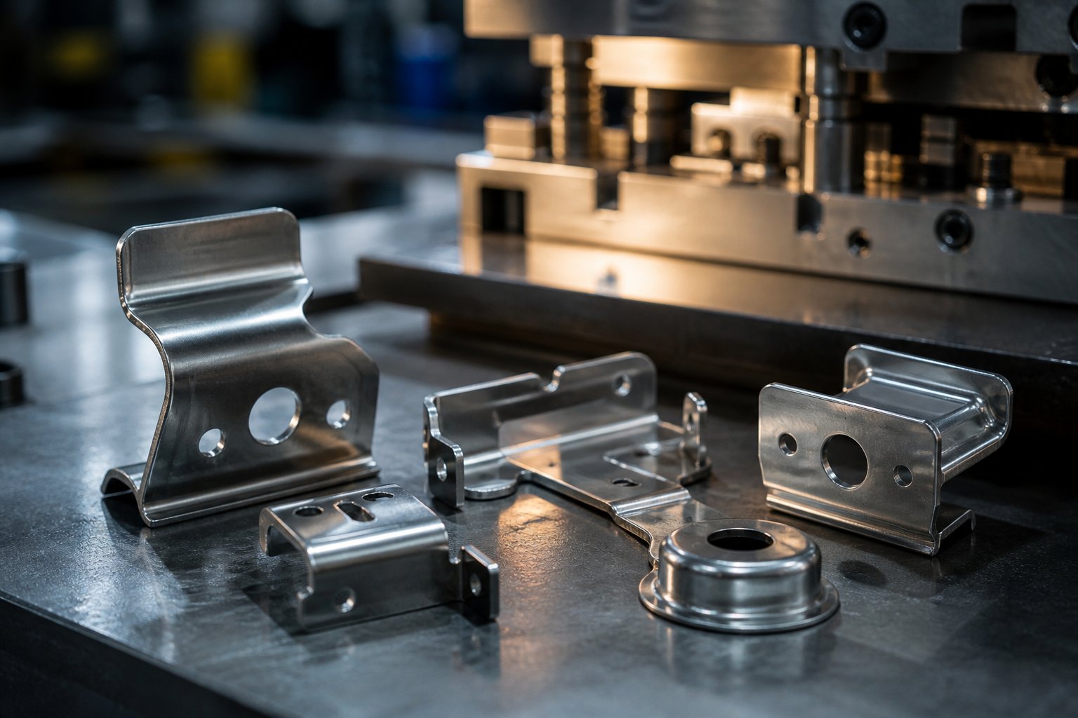
What Are Dies Stamped Parts and Why They Matter
Pick up any metal bracket, electrical terminal, or automotive clip and you're likely holding a component that started as flat sheet metal. It reached its final shape not through machining or casting, but through controlled force applied by precision tooling inside a stamping press. These are dies stamped parts, and they account for a massive share of the metal components found in everything from consumer electronics to heavy equipment.
What Are Dies Stamped Parts
Dies stamped parts are metal components produced by pressing sheet metal into or through hardened tooling (called a die) that cuts, bends, or forms the material into a specific geometry in one or more press strokes.
So what is a die, exactly? It is a specialized, one-of-a-kind precision tool engineered to cut and form sheet metal into a desired shape or profile. The die's working sections are typically made from hardenable tool steel or carbide, and a die is used to execute precise operations-piercing, blanking, bending, drawing-that transform raw material into finished stamping parts.
Imagine a cookie cutter, but one that operates under tons of force, holds tolerances as tight as 0.0002 inches, and runs millions of cycles without losing accuracy. That's the scale of engineering behind stamping dies. Unlike subtractive processes that remove material, dies and stamping work together to reshape metal with minimal waste, making the process fast, repeatable, and cost-effective at volume.
Why Die Design Determines Part Outcomes
Here's where most engineers get tripped up: they specify a part's geometry, tolerances, and material on a drawing without considering how tooling decisions upstream will dictate whether those specs are achievable. The relationship between die design and part quality is direct and unforgiving.
Every characteristic of a finished stamped part traces back to something inside the die:
- Edge quality depends on the cutting clearance between punch and die block-typically around 10% of material thickness for clean shear.
- Dimensional accuracy relies on guide systems, pilots, and the structural rigidity of die shoes keeping everything in alignment stroke after stroke.
- Surface finish is influenced by die surface condition, lubrication delivery, and forming speed.
- Geometric consistency over long production runs hinges on wear-resistant materials and proper die maintenance intervals.
When die stamps hit the sheet metal, the tooling isn't just shaping a part-it's encoding quality into every piece. A well-designed die produces thousands of identical components with no secondary operations. A poorly designed one generates scrap, burrs, dimensional drift, and costly downtime.
This article takes a part-first perspective. Instead of cataloging die components in isolation, we'll trace how each tooling decision-die type, material selection, clearance strategy, forming method-shows up in the finished component you hold in your hand. Whether you're specifying stamped parts for a new product or troubleshooting quality issues on an existing line, understanding what are dies and how they shape outcomes gives you the leverage to get parts made right the first time.
Types of Stamping Dies and When to Use Each
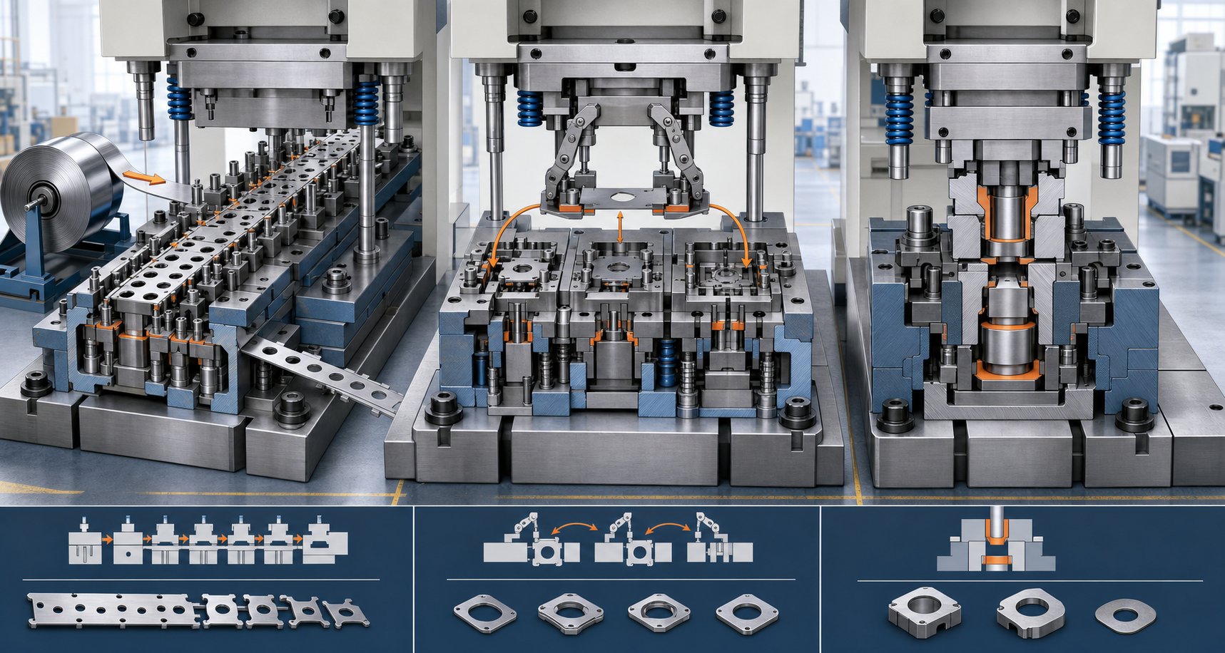
Die type is the first fork in the road. Choose wrong and you're either overpaying for tooling you don't need or fighting quality issues because the die architecture doesn't match your part's geometry. Three primary types of stamping dies cover the vast majority of production scenarios: progressive, transfer, and compound. Each one handles different combinations of part complexity, size, and volume-and each produces fundamentally different cost-per-part economics.
Which metal stamping dies architecture fits your project? That depends on what your finished part looks like, how many you need, and how tight your tolerances are.
Progressive Dies for High-Volume Complex Parts
Progressive dies are the workhorses of high-volume stamping. A continuous strip of sheet metal feeds into the die and advances through a series of stations, each performing a different operation-piercing a hole, notching an edge, forming a bend, trimming a profile. By the time the strip reaches the final station, a fully finished part separates from the carrier strip.
You'll notice that progressive dies never release the workpiece between operations. The strip itself acts as the conveyor, keeping every feature in precise alignment from station to station. This makes them ideal for small to mid-sized parts with multiple features: electrical contacts, brackets, clips, connectors, and terminals.
The tradeoff? Higher upfront tooling cost and limited flexibility for design changes once the die is built. But for production runs in the hundreds of thousands or millions, the cost per part drops significantly, making progressive dies extremely economical over time. Cycle speeds are fast-often 100 to 1,500 strokes per minute depending on part complexity-because there's no manual handling between operations.
Transfer Dies for Large or Deep-Drawn Parts
When a part is too large to stay connected to a strip, or its geometry requires deep draws and complex three-dimensional forming, transfer dies step in. Instead of moving through the die on a carrier strip, individual blanks are cut first and then mechanically transferred between independent stations using grippers or shuttle mechanisms.
This separation gives transfer dies a key advantage: each station can perform heavy forming operations-deep drawing, re-striking, flanging-without the geometric constraints of strip progression. Large automotive panels, cylindrical housings, and deep cup-shaped components typically require this approach.
Transfer dies also save material. Because there's no connecting web between parts (the way progressive dies use a carrier strip), you eliminate that scrap, which reduces material costs on each piece. The tradeoff is longer setup times, higher tooling complexity, and slightly slower cycle speeds compared to progressive stamping.
Compound Dies for Flat Precision Parts
Compound dies take a different approach entirely. They perform multiple cutting operations-blanking and piercing, for example-in a single press stroke. Everything happens simultaneously rather than sequentially. This makes them well-suited for flat parts that require tight positional accuracy between features, like washers, shims, flat contact plates, and gaskets.
Because all cutting happens at once, the relationship between holes, slots, and the outer profile stays locked in. There's no cumulative positioning error from station-to-station transfer. For sheet metal stamping dies producing simple flat geometries at moderate volumes, compound dies deliver excellent precision at lower tooling cost than progressive alternatives.
The limitation is clear: compound dies can't handle bending, forming, or deep drawing. They're a single-plane tool. If your part needs any three-dimensional shaping, you'll need a different stamping die architecture or secondary operations downstream.
Comparing the Three Die Architectures
| Criteria | Progressive Die | Transfer Die | Compound Die |
|---|---|---|---|
| Best Part Geometry | Small to mid-sized parts with multiple features (bends, holes, forms) | Large parts, deep-drawn shapes, complex 3D geometry | Flat parts requiring precise hole-to-edge relationships |
| Typical Production Volume | High (100K to millions) | Medium to high (10K to hundreds of thousands) | Low to medium (1K to 100K) |
| Achievable Tolerances | +/-0.05 mm to +/-0.1 mm | +/-0.1 mm to +/-0.2 mm | +/-0.025 mm to +/-0.05 mm |
| Relative Tooling Cost | High | High | Low to medium |
| Cycle Speed | Very fast (100-1,500+ SPM) | Moderate (15-80 SPM) | Moderate to fast (50-300 SPM) |
Decision Framework: Choosing Your Die Type
Selecting between these three architectures doesn't have to be guesswork. Walk through these questions in order, and the right answer usually becomes obvious:
- Is the part flat with no bends or forms? If yes, a compound die likely gives you the best precision-to-cost ratio.
- Does the part require multiple operations (bends, draws, forms) in addition to cutting? If yes, you need either a progressive or transfer die.
- Can the part remain attached to a carrier strip throughout all operations? If the part is small enough and doesn't require deep draws, a progressive die is your best bet for speed and cost-per-piece.
- Is the part too large for strip feeding, or does it require deep drawing beyond what strip progression allows? If yes, a transfer die handles the geometry without compromise.
- What is your annual production volume? High volumes (100K+) justify the tooling investment in progressive dies. Medium volumes may favor transfer or compound depending on complexity. Low volumes may point toward compound dies or simpler tooling with secondary operations.
- How tight are your tolerances? If flatness and hole position accuracy are critical on a simple part, compound dies deliver the tightest results. If feature-to-feature accuracy matters across complex geometry, progressive dies with precision pilots maintain consistency.
The stamping die you choose sets the ceiling for what your finished part can achieve-its tolerances, its surface quality, and its production economics. But die architecture is only half the equation. Inside each of these die types, a set of critical components works together to actually shape the metal, and understanding how those components interact is what separates a good part from a scrapped one.
Key Stamping Die Components That Shape Your Parts
A die architecture gives you the blueprint, but the individual stamping die components inside that structure do the actual work. Each one plays a specific role in cutting, guiding, or controlling the sheet metal as it transforms into a finished part. When these die components work in harmony, you get clean edges, accurate dimensions, and repeatable quality run after run. When even one element is off, defects show up fast.
Think of a die assembly as a precision instrument with dozens of interdependent parts. Understanding how each piece influences the metal gives you real leverage when specifying tolerances or diagnosing quality problems on the press floor.
Punch and Die Block Interaction
The sheet metal punch and die block relationship is the heart of every cutting operation. The punch descends into the sheet metal while the die block provides the opposing cutting edge below. The gap between these two surfaces-known as cutting clearance-controls almost everything about your cut edge quality.
When clearance is optimized (typically 5 to 15% of material thickness depending on the alloy), the metal shears cleanly. The punch pushes the material past its shear strength, and the fracture propagates neatly between the punch edge and the die block opening. The slug drops freely through the die block, and the remaining hole or profile has a smooth shear zone with minimal burr.
Set that clearance too tight and you spike the cutting force, accelerate punch wear, and risk tool breakage. Too loose and the material rolls rather than shears, producing ragged edges and oversized burrs that require secondary finishing. The die block's bore geometry also affects slug retention-if slugs don't eject cleanly, they stack up and damage the next part or the punch itself.
Die Shoes, Guide Systems, and Alignment
Imagine running a press at 600 strokes per minute with the upper and lower halves misaligned by even a few thousandths of an inch. Every punch would land off-center, cutting clearance would shift to one side, and your parts would show uneven edge quality or dimensional drift. That's why die shoes and guide systems matter so much.
Die shoes are thick steel or aluminum plates that serve as the structural foundation for the entire die assembly. The upper shoe carries the punches and strippers; the lower shoe holds the die blocks, lifters, and the die pad plate that supports forming sections. Together, they must remain perfectly parallel and rigid under load.
Connecting the two shoes, guide pins and bushings maintain alignment throughout the press stroke. These precision-ground components are manufactured to tolerances within 0.0001 inches. Ball-bearing style guide pins reduce friction and allow faster press speeds, while friction-style pins provide additional heeling to resist lateral forces. Both types ensure the upper and lower halves register exactly every cycle, keeping your stamping die parts in proper relationship to each other.
Lifters, Strippers, and Material Control
Cutting and forming get all the attention, but material control components quietly determine whether your progressive die runs smoothly or jams every fifty strokes.
Lifters elevate the metal strip between stations so it clears the die block surfaces and any formed features below. Without them, the strip would drag across the lower die, causing scratches, misfeeds, and positional errors. Spring-loaded lifters raise the strip to a consistent height, allowing it to advance freely to the next station.
Strippers serve double duty. They hold the sheet flat against the die block during cutting (preventing distortion), and they pull the material off the punch as it retracts. Without a stripper, the sheet metal would lift with the punch and lose its position entirely. Mechanical strippers use spring pressure while urethane strippers rely on elastic compression-both keep the material where it belongs.
Pilots are precision pins that enter previously pierced holes as the strip advances into each station. They fine-tune the strip's position before any cutting or forming takes place, correcting any feed error and ensuring feature-to-feature accuracy stays within spec across the entire part.
Component Reference: What Each Part Does
- Punches - The cutting or forming tools that press into the sheet metal to create holes, profiles, or shaped features.
- Die blocks (buttons) - Hardened inserts that provide the opposing cutting edge; their bore size offsets larger than the punch by the specified clearance.
- Die shoes - Upper and lower steel plates that serve as the structural foundation for mounting all working components.
- Strippers - Spring-loaded plates or urethane elements that hold the sheet flat during cutting and strip it off the punch on retraction.
- Lifters - Spring-driven rails or pins that elevate the strip for smooth progression between stations.
- Pilots - Precision locating pins that enter pre-pierced holes to align the strip before each operation.
- Springs - Mechanical or nitrogen gas elements that provide controlled force for strippers, lifters, and pressure pads.
- Backing plates - Hardened plates positioned behind punches to distribute impact loads and prevent the punch heads from embedding into softer die shoes.
Every one of these stamping die components contributes to the final part outcome. A worn pilot allows positional drift. A weak stripper spring lets material lift and distort. A cracked backing plate lets a punch push into the shoe. The die assembly works as a system-and your part quality is only as good as the weakest link in that system.
Of course, these components don't operate in a vacuum. The material you're stamping-its thickness, hardness, and ductility-places demands on every element inside the die and dictates how aggressively each one wears over time.
How Workpiece Material Influences Die Selection
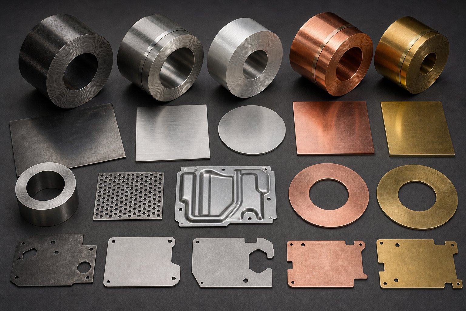
A die built for mild steel will not perform the same way when you run stainless steel through it. The material on the coil dictates nearly every engineering parameter inside the tool: cutting clearance, punch geometry, forming radii, spring force, press tonnage, and even the surface coating on tooling components. Ignore these material-driven requirements and you'll burn through punches, generate excessive burrs, or crack parts during forming.
When specifying dies stamped parts, the material datasheet isn't just a procurement detail-it's the starting point for every tooling decision. Four properties matter most: tensile strength, hardness, ductility, and thickness. Each one changes how the sheet metal die must be designed to produce acceptable parts.
Steel and Stainless Steel Stamping Considerations
Steel remains the most common material for stamped components, but "steel" covers a wide range of behaviors. Mild steel (typically under 350 MPa tensile strength) is forgiving-it shears cleanly, forms without excessive springback, and causes moderate die wear. Stainless steel is a different animal entirely.
Stainless grades like 304 and 316 have tensile strengths exceeding 500 MPa, work-harden rapidly during forming, and generate significantly more heat at the punch-to-material interface. For steel stamping dies processing these harder alloys, you'll notice several engineering adjustments become mandatory:
- Tighter clearances - Harder materials require increased clearance percentages to prevent premature punch fracture and excessive cutting forces. Stainless typically needs 10-15% of material thickness per side, compared to 6-10% for mild steel.
- Higher forming forces - Press tonnage requirements jump 50-60% when moving from mild steel to stainless. Undersized presses lead to incomplete forming, coining marks, and accelerated wear across all tooling components.
- Springback compensation - Stainless steel's higher yield-to-tensile ratio means more elastic recovery after bending. Die designers must over-bend by 2-4 degrees (sometimes more) to hit target angles, and forming punches may need modified radii to account for the kickback.
- Accelerated die wear - The abrasive nature of stainless demands premium stamping die steel for punch and die block construction. D2 or M2 tool steels, often with TiN or AlCrN coatings, become necessary to maintain edge sharpness through longer production runs.
The result? Steel stamping dies built for stainless cost more upfront because they require better materials, tighter manufacturing tolerances, and more robust press frames. But that investment pays off in consistent part quality and longer intervals between regrinds.
Aluminum and Copper Alloy Behavior in Dies
Aluminum brings a completely different set of challenges to the stamping process. It's roughly one-third the density of steel and relatively soft-which sounds like it should be easy to stamp. In practice, that softness creates problems steel never does.
The biggest issue with aluminum stamping dies is galling. Aluminum is a "sticky" metal that tends to cold-weld microscopic particles onto the die surface during high-pressure contact. Once galling starts, it snowballs: each subsequent stroke picks up more material, scratches the next part, and eventually damages the die beyond simple polishing. Preventing galling requires a multi-layer strategy:
- Die coatings - PVD coatings like Titanium Nitride (TiN) or Diamond-Like Carbon (DLC) create a non-stick barrier between the aluminum and the tool steel surface.
- Surface finish - Mirror-polishing forming surfaces reduces friction-generated heat, which is the primary trigger for adhesive wear.
- Tool steel selection - High-vanadium steels (such as CPM 10V) offer superior resistance to the adhesive wear aluminum causes.
- Specialized lubrication - Chlorine-free synthetic fluids provide boundary lubrication without staining the aluminum surface.
Aluminum also exhibits pronounced springback-more than steel-because its modulus of elasticity is roughly one-third that of steel (approximately 10,000 ksi versus 30,000 ksi). Bends that would hold angle in steel will spring back significantly in aluminum, requiring over-bending or stress-relief features built into the die.
Copper and brass alloys sit at the other end of the softness spectrum. They form easily with minimal springback, but their softness means they're prone to surface marking from rough die surfaces. Copper stamping typically requires polished tooling and careful stripper pressure settings to avoid cosmetic damage. On the upside, copper alloys cause very little die wear, so tooling life is excellent even with standard tool steels.
How Material Thickness Drives Die Engineering
Regardless of the alloy, stock thickness is the single most influential variable in clearance calculation. The industry-standard formula is straightforward:
Cutting Clearance (per side) = Material Thickness x Clearance Coefficient
The clearance coefficient typically ranges from 5% to 10% of material thickness, depending on the alloy's hardness and the desired edge quality. Precision applications use the lower end (around 5%) for minimal burr and smooth shear surfaces. General stamping uses 8-10% to extend die life and reduce cutting forces.
For example, stamping 1.0 mm mild steel with an 8% coefficient gives you 0.08 mm clearance per side. Switch to 2.0 mm stainless steel at 12% and you're looking at 0.24 mm per side-a threefold increase that demands completely different die block dimensions and punch sizing.
Thickness also drives these related decisions:
- Punch strength - Thicker materials require more cutting force, which means larger punch cross-sections to avoid buckling.
- Stripper force - Thicker stock grips the punch more tightly, demanding stronger springs or nitrogen cylinders to strip the material reliably.
- Minimum feature size - The general rule is that the smallest hole diameter shouldn't be less than the material thickness. Punch anything smaller and you risk tool breakage.
- Forming radii - Minimum bend radius scales with thickness. Steel typically allows a bend radius equal to 1T (one times thickness), while aluminum often requires 2T or 3T to avoid cracking.
Material Comparison for Stamped Parts
| Material | Typical Thickness Range | Relative Forming Force | Springback Tendency | Die Wear Rate |
|---|---|---|---|---|
| Mild Steel | 0.3 mm - 6.0 mm | Moderate (baseline) | Low to moderate | Moderate |
| Stainless Steel | 0.2 mm - 4.0 mm | High (1.5-1.7x mild steel) | High | High |
| Aluminum | 0.3 mm - 6.0 mm | Low (0.3-0.5x mild steel) | High (low modulus) | Low (but galling risk) |
| Copper | 0.1 mm - 3.0 mm | Low to moderate | Very low | Very low |
| Brass | 0.2 mm - 4.0 mm | Moderate | Low | Low |
Material selection doesn't just determine what goes on the coil-it ripples through every tooling decision from punch hardness to press tonnage to maintenance intervals. Getting these parameters right at the design stage prevents the downstream problems that eat into production quality: burrs that grow too fast, bends that won't hold angle, and surfaces that mark or gall within the first thousand strokes.
Those downstream problems deserve their own examination. Even with perfectly matched materials and clearances, specific defects can appear in production-and each one traces back to a controllable root cause inside the die.
Common Defects in Die Stamped Parts and How to Prevent Them
Even a perfectly engineered die eventually produces a defective part. The difference between a well-run stamping operation and a scrap-heavy one comes down to understanding why defects happen and addressing root causes before they escalate. Burrs, springback, wrinkles, cracks, and thinning are the five defects that account for the majority of rejected die stamped parts. Each one traces directly back to a specific tooling condition or process parameter that can be controlled.
Burr Formation and Cutting Clearance Control
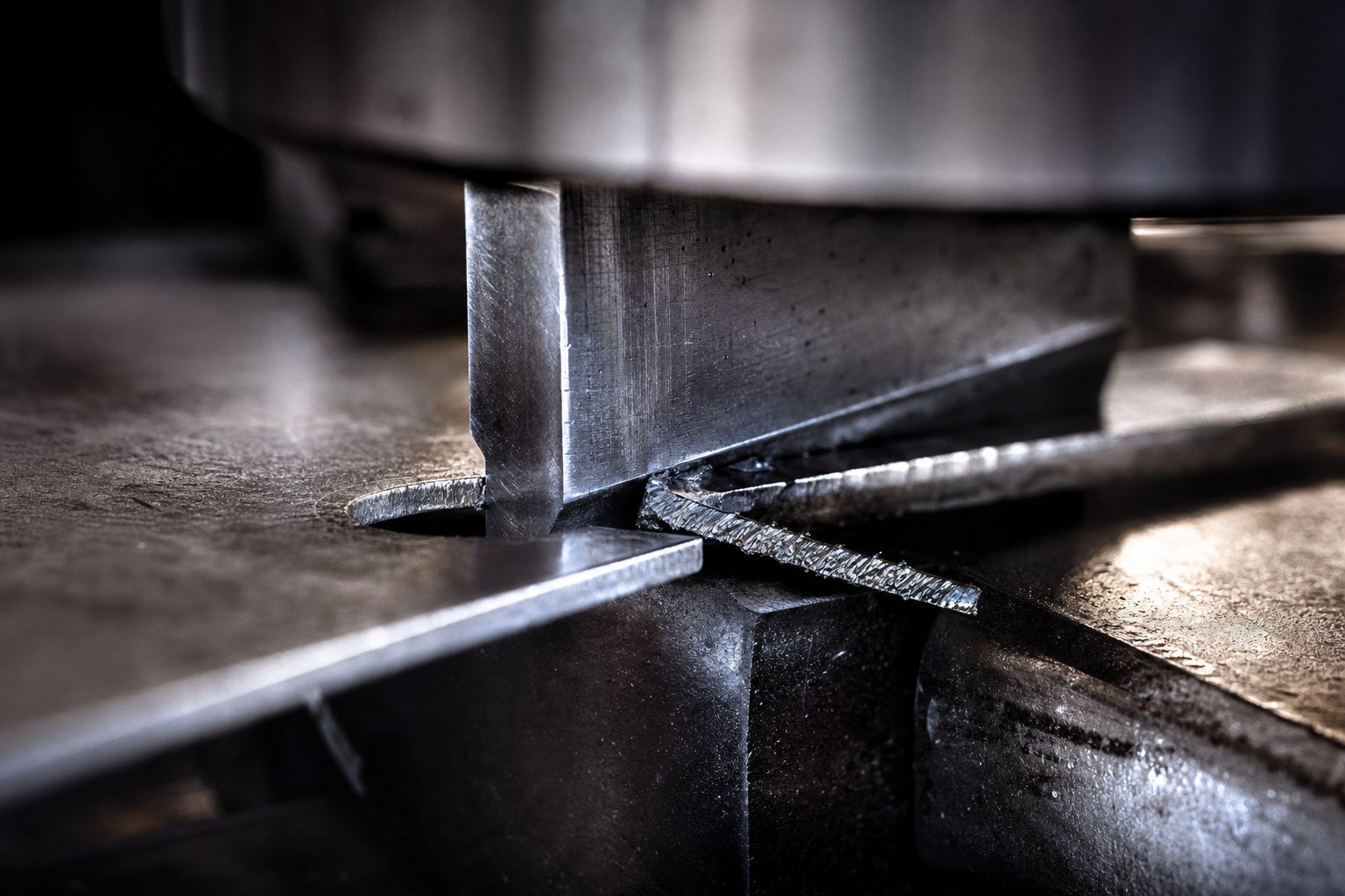
Burrs are raised, sharp edges that form along the cut profile of a stamped part after punching, blanking, or trimming. They're the most common complaint in stamped part production, and almost always point to a clearance problem between the metal punches and die block.
Here's what happens inside the die during a cutting stroke: the punch contacts the sheet, pushes it past its shear strength, and the material fractures along a line connecting the punch edge to the die block edge. When clearance is optimized, those fracture lines meet cleanly, producing a smooth shear zone with minimal rollover and a tight, nearly invisible burr. When clearance is too tight, cutting forces spike and the material tears rather than shearing. When clearance is too large, the metal rolls into the gap before fracturing, leaving a ragged edge and oversized burr.
The industry guideline for mild steel is 5-8% of material thickness per side. Stainless steel and higher-strength alloys push that range upward to 10-15%. Getting this number right at the design stage is critical, but it's only half the battle.
Die wear introduces a second variable. As stamping die punches and die blocks cycle through production, their cutting edges gradually round over. This progressive dulling effectively increases the functional clearance beyond its designed value, and burr height grows incrementally with each thousand strokes. Monitoring burr height during production provides an early warning signal for when regrinding or punch replacement is needed. A part that measured 0.05 mm burr at setup might creep to 0.15 mm by the 200,000th hit-well beyond acceptable limits for many applications.
Springback, Wrinkling, and Cracking Prevention
Forming defects are trickier than cutting defects because they involve the material's behavior under stress rather than a simple clearance measurement.
Springback is the elastic recovery of metal after bending force is released. The part partially returns toward its original flat shape, leaving you with a bend angle that's a few degrees off target. High-strength materials exhibit more springback because they retain more elastic energy. Solutions include compensating the die angle during design (over-bending by the expected springback amount), using bottoming or coining strokes that plastically deform the bend apex, and adding stiffening ribs near the bend line to lock the geometry.
Wrinkling appears as wave-like buckles on the flange or wall of drawn parts. It happens when compressive stress exceeds the sheet's resistance to buckling-typically because the blank holder force is too low or draw beads aren't restraining material flow effectively. Increasing blank holder pressure, optimizing draw bead geometry, and adjusting lubrication distribution usually solve the problem.
Cracking occurs when tensile strain exceeds the material's ductility limit. You'll see it at tight bend radii, deep-drawn corners, and areas where the material thins excessively. Common root causes include too-small punch radii, aggressive single-stage drawing, and poor grain direction alignment. Prevention strategies focus on spreading the strain: larger radii, multi-stage forming, intermediate annealing for deep draws, and aligning critical bends across the grain direction rather than parallel to it.
The Role of Bypass Notches in Material Flow
Progressive die stamping adds a defect category that other die types don't face: misfeed-related dimensional errors. When the strip doesn't advance the exact pitch distance between strokes, every feature on the part shifts out of position. This is where negative and positive bypass notches in sheet metal stamping dies become essential.
A bypass notch (also called a pitch notch or French notch) is a small section of material cut away from one or both edges of the strip at the beginning stations of a progressive die. The purpose of bypass notches in stamping dies is threefold: they provide a solid mechanical stop that prevents overfeeding, they remove edge camber that would otherwise cause the strip to track unevenly, and they create a reference surface for feed-length verification sensors.
Negative bypass notches cut material away from the strip edge, creating an open slot that a stop block engages. Positive bypass notches lance a small tab downward, creating a protruding feature that registers against a stop surface in the die. Both approaches control strip progression, but they serve different design contexts. Negative notches are more common for wider, thicker strips where edge camber is a concern. Positive notches (lance-and-flange style) work well for narrow carriers because they stiffen the carrier and aid feeding without producing a loose slug that requires ejection.
Understanding the bypass notches sheet metal forming purpose helps explain why some progressive dies run flawlessly while others misfeed constantly. Without these notches, even high-precision servo feeders can't guarantee that the strip won't creep past its intended position-one severe misfeed can crash an entire die, costing far more than the small amount of material the notch consumes.
Defect-to-Solution Reference
- Excessive burrs - Cause: worn cutting edges or incorrect punch-to-die clearance. Solution: maintain proper clearance (5-15% of material thickness per side depending on alloy), regrind or replace punches on schedule, and verify tool alignment.
- Springback - Cause: elastic recovery in bends, especially in high-strength materials. Solution: over-bend by the compensated angle, use bottoming/coining strokes, or add stiffening features.
- Wrinkling - Cause: insufficient blank holder force or inadequate draw bead restraint. Solution: increase holding pressure, redesign draw beads, and optimize blank shape to control material flow.
- Cracking - Cause: tensile strain exceeding material ductility at sharp radii or deep draws. Solution: increase forming radii, use multi-stage drawing, select higher-ductility material, and align bends across grain direction.
- Material thinning - Cause: excessive draw depth or too-small punch/die radius concentrating strain. Solution: optimize blank size, improve lubrication, reduce draw ratio per stage, and redistribute strain through simulation-guided die geometry.
- Misfeed/dimensional shift - Cause: strip overfeeding or positional drift in progressive dies. Solution: incorporate bypass notches for positive pitch control, maintain pilot pin condition, and use feed-verification sensors.
Each of these defects is preventable at the die design stage. The challenge is that solutions often interact-tightening clearance to reduce burrs increases cutting force, which accelerates punch wear, which eventually brings burrs back. Effective defect prevention requires a systems-level view of how clearance, material flow, notch design, and forming parameters all work together. For complex progressive dies where bypass notch geometry, burr control, and material flow optimization intersect, working with experienced tooling specialists like YICHEN can help engineers resolve these interrelated variables before hard tooling is released.
Preventing defects is one side of the quality equation. The other side is knowing how much quality to build into the die in the first place-and that decision depends on production volume, expected tool life, and the classification system that governs how dies are constructed.
Die Classification and Production Volume Decisions
How much quality should you build into a die? It's not a trick question. Overbuilding tooling for a 5,000-piece prototype run wastes money. Underbuilding it for a 3-million-piece annual commitment wastes far more-through downtime, rework, and premature tool replacement. The industry solves this problem through a die classification system that matches tooling investment to production reality.
Three classes-A, B, and C-define the spectrum of die tooling quality, and each one carries specific implications for part tolerances, surface finish, tool life, and cost per piece. Yet most engineers encounter these terms without a clear explanation of what separates one class from another or when each makes economic sense.
Die Classes and What They Mean for Part Quality
Think of die classes as tiers of engineering precision. A standard die in Class C territory is built for a fundamentally different purpose than a Class A stamping die set designed to run millions of cycles. Here's how they break down:
Class A - Maximum Precision, Maximum Life
Class A tooling sits at the top of the quality pyramid. These metal stamping die sets are engineered for extreme reliability, built from the toughest tool steels available, and manufactured to the tightest dimensional tolerances. According to Master Products Co., Class A dies serve high-quality production applications including precision components with complex geometries, close tolerances, and premium surface finishes-automotive body panels and consumer appliances being prime examples.
Class A is further divided into two subtypes:
- Type 1 - Larger dies used for stretching and drawing exterior panels. These produce parts that are prominently visible on the finished product, so every stamped piece must be entirely smooth and defect-free.
- Type 2 - The highest degree of toolmaking precision possible. Built from specialized tool steels, carbide inserts, high-performance ceramics, and aluminum die shoes. If your project involves extremely high volumes or invariably close tolerances, Type 2 progressive dies are the answer.
In some applications, a Class A die will produce several million parts over its lifetime without requiring major rebuild. That longevity comes from material choices (carbide at critical wear points, premium tool steels elsewhere) and construction methods that prioritize rigidity and thermal stability over initial cost savings.
Class B - The Production Workhorse
Class B tooling dies represent the most common category in commercial and industrial stamping. These dies are still built to close tolerances from durable tool steels, but they're designed with a defined production volume in mind rather than engineered for indefinite service. You'll specify a target quantity-say 500,000 pieces-and the Class B die is built to reliably produce that volume with some margin beyond.
The practical difference? Class B uses standard D2 or A2 tool steels without the carbide inserts or exotic coatings found in Class A builds. Guide systems are precision-ground but may not include the ball-bearing upgrades that extend high-speed cycle life. The result is a stamping die set that delivers excellent part quality at a lower investment, with the understanding that maintenance intervals will be shorter and total tool life is finite.
Class C - Short-Run and Prototype Tooling
Class C is the entry point. These are lower-cost dies suitable for low- to mid-volume projects, prototyping runs, or applications where tight tolerances and premium finishes aren't required. A Class C die might use softer tool steels, simplified guide systems, and less complex construction to keep costs down and lead times short.
When do you choose Class C? When you need 500 to 10,000 parts to validate a design, test market fit, or bridge production while permanent tooling is being built. The parts won't match the consistency of Class A output, but they'll be functional and representative of the final geometry.
Production Volume as a Die Investment Framework
Die class selection isn't subjective-it's driven by math. The fundamental question is simple: does the per-part cost reduction from better tooling justify the higher upfront investment?
Consider the break-even logic. A Class C die might cost $15,000 but requires secondary deburring operations at $0.05 per part. A Class A die for the same component might cost $80,000 but eliminates those secondary operations entirely. At what volume does the expensive die become the cheaper option? In this example, around 1.4 million parts. Below that number, the simple tooling wins. Above it, the Class A investment pays for itself and keeps saving money with every stroke.
Material choice inside the die follows the same logic. Tool steel dies cost 3-5x less than carbide equivalents, but carbide's wear resistance can be 10 to 30 times greater. A tool steel punch might need regrinding every 100,000 hits. A carbide insert at the same station could run 2-3 million hits before requiring attention. For high-volume production, the carbide die delivers a lower total cost of ownership despite the steep initial price.
Hybrid approaches bridge the gap. Using carbide inserts at critical high-wear points within a tool steel die body provides exceptional wear resistance where it matters most while keeping overall die cost manageable. Advanced coatings like TiN or TiCN applied to tool steel components can also extend service life significantly, narrowing the performance gap between uncoated steel and solid carbide without the full cost premium.
Volume Tiers and Die Class Recommendations
- Prototype / Pre-production (under 5,000 parts) - Class C tooling. Expect tool life of 5,000-50,000 strokes. Use standard tool steels, simplified construction. Accept wider tolerances and plan for secondary operations. Goal: validate part geometry at minimum investment.
- Low volume (5,000-100,000 parts annually) - Class C or low-end Class B tooling. Expect tool life of 50,000-500,000 strokes. Tool steel construction with moderate hardness (58-62 HRC). Suitable for parts where ±0.1 mm tolerances are acceptable.
- Medium volume (100,000-500,000 parts annually) - Class B tooling. Expect tool life of 500,000-1,500,000 strokes with scheduled regrinds. High-quality tool steels (D2, A2), precision guide systems, and engineered maintenance intervals. This tier often represents the sweet spot where tooling investment balances against per-part economics.
- High volume (500,000-2,000,000 parts annually) - Class A Type 1 tooling. Expect tool life exceeding 2,000,000 strokes. Premium tool steels with selective carbide inserts at high-wear stations. Tight tolerances (±0.05 mm or better), minimal secondary operations, and optimized cycle speeds.
- Very high volume (2,000,000+ parts annually) - Class A Type 2 tooling. Expect tool life of 5,000,000+ strokes. Full carbide inserts at all cutting stations, specialized die shoe materials, and progressive die architectures engineered for maximum uptime. The die itself becomes a significant capital asset with its own maintenance schedule and rebuild program.
Notice the pattern: as volume increases, you invest more in the die to reduce per-part cost, eliminate secondary operations, extend maintenance intervals, and minimize downtime. The die class isn't about prestige-it's about matching your tooling investment to the economic reality of your production run.
Choosing the right class also determines what forming operations the die can sustain over its lifetime. A Class B die handling simple blanking and piercing may last well beyond its rated volume. That same class attempting high-precision coining or deep drawing under tight tolerances will wear faster because forming operations place sustained compressive loads on tooling surfaces-loads that demand the material resilience only higher-class construction provides.
Forming Operations That Define Stamped Part Geometry
Cutting separates metal. Forming reshapes it. Every stamped component that goes beyond a flat profile-every bracket with a bend, every housing with a drawn wall, every contact with an embossed rib-owes its geometry to a forming operation performed inside the die. These operations expose the sheet metal to controlled tension, compression, or both, and the balance between force applied and material properties determines whether you get a precise part or a pile of scrap.
What makes forming tricky is that you're working against the metal's natural resistance to permanent deformation. The sheet wants to spring back, buckle, thin out, or crack. A well-designed forming station anticipates those tendencies and channels them into a predictable outcome. Understanding how each type of die pressing operation transforms flat stock into three-dimensional geometry gives you the ability to specify stamping components that are actually producible-and to troubleshoot problems when parts come off the press out of spec.
Bending and Flanging Operations in Stamping Dies
Bending is the most common forming operation in stamping. It deforms the sheet along a straight axis, creating features like tabs, channels, brackets, and mounting flanges. Sounds simple-but achieving the correct bend angle consistently across a production run is one of the harder challenges in stamped part manufacturing.
Three primary bending methods show up inside stamping dies:
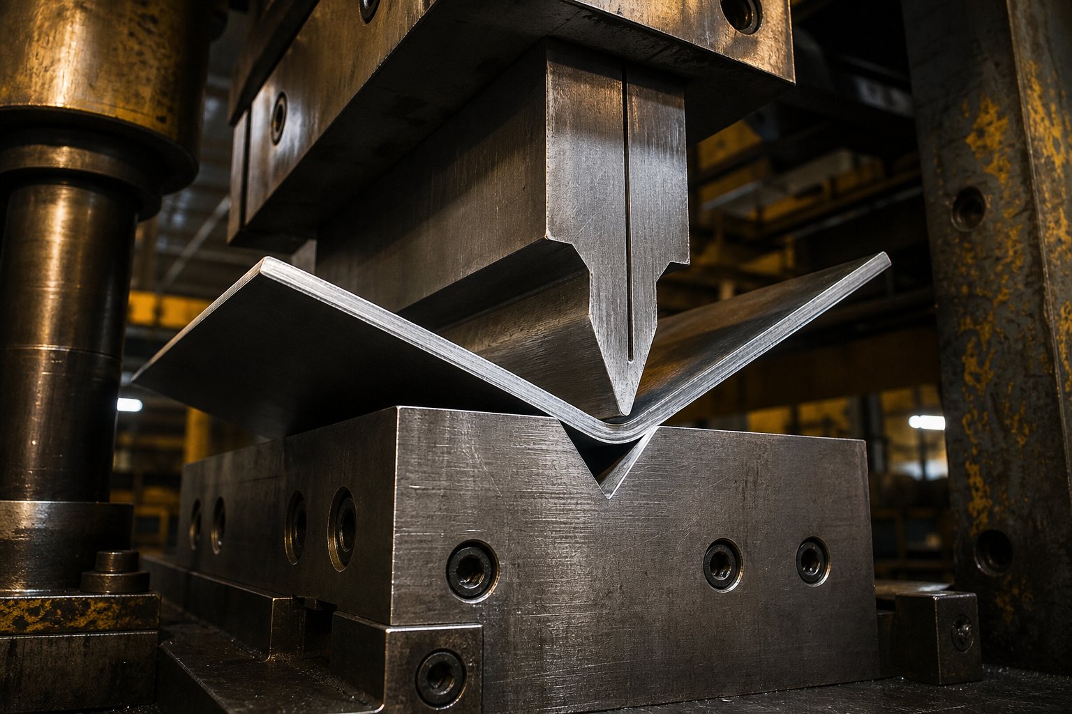
- V-bending - The punch forces the sheet into a V-shaped cavity in the die block. The final angle depends on how deep the punch penetrates. Air bending (where the punch doesn't bottom out) offers flexibility because different angles can be achieved with the same tooling. Bottoming (where the punch fully seats) provides tighter angle control but locks you into one geometry.
- U-bending - The punch drives the sheet into a U-shaped channel, forming two parallel bends in a single stroke. A pressure pad beneath the punch holds the sheet flat during forming, preventing the bottom from bowing. This method creates channel sections and C-shaped profiles efficiently.
- Wipe bending - One edge of the sheet is clamped while a punch wipes the free portion over a radius. This approach works well inside progressive dies because it doesn't require the sheet to move relative to the strip carrier. It's the go-to method for creating flanges and tabs on parts that remain connected to the strip during processing.
Regardless of the method, every bend introduces both compression on the inside radius and tension on the outside radius. That dual stress state is why cracking happens on the outer surface when the bend radius is too tight-the material literally runs out of stretch.
Minimum bend radius rules exist to prevent this failure. The general guideline is that the inside bend radius should equal at least one times the material thickness (1T) for mild steel. Harder materials need more room: stainless steel often requires 1.5T to 2T, and aluminum alloys like 6061-T6 may need 2T to 3T depending on temper and grain direction.
Grain direction matters because metal is slightly weaker perpendicular to the rolling direction. Bending across the grain (perpendicular to roll direction) allows tighter radii without cracking. Bending along the grain forces the crack-prone outer fibers to stretch in their weakest orientation. When possible, orient critical bends across the grain-it's a free improvement in formability that costs nothing in die complexity.
Flanging follows the same principles as bending but operates along a curved axis instead of a straight one. A stretch flange (convex curve) puts the outer edge in tension and risks splitting. A shrink flange (concave curve) compresses the outer edge and risks wrinkling. Both require careful attention to flange width and relief geometry to stay within material limits.
Drawing, Coining, and Embossing for Complex Part Geometry
When a part needs depth-a cup, a shell, a housing-simple bending won't get you there. Drawing, coining, and embossing each use fundamentally different approaches to create three-dimensional stamped components from flat stock.
Deep Drawing
Drawing is the most demanding forming operation. A flat blank is pulled into a die cavity by a punch, transforming it into a hollow, cup-shaped part through controlled material flow. The key distinction from other forming methods: the metal actually flows into the die rather than simply stretching over a form.
A pressure-loaded blank holder (draw pad) sits on top of the blank's outer edge and controls how much material feeds into the cavity. Too little holding force and the metal wrinkles as it compresses inward. Too much and the material can't flow, leading to thinning or tearing at the punch radius. That balance between blank holder pressure and material flow defines whether a drawing operation succeeds or fails.
Deep-drawn parts include oil pans, cookware, automotive door panels, cylindrical housings, and beverage can bodies. The achievable draw depth depends on material ductility, blank diameter-to-punch ratio, and lubrication. For standard mild steel, a first-draw reduction ratio (blank diameter to punch diameter) of about 2:1 is typical. Deeper parts require multiple draw stages with intermediate annealing to restore ductility.
Coining
Coining achieves what other forming methods can't: extremely tight dimensional tolerances through full plastic deformation. Unlike bending or drawing-where elastic springback shifts the final geometry-coining squeezes the metal under such extreme pressure that virtually no elastic recovery occurs. The material conforms completely to the punch and die cavity surfaces.
Imagine the coins in your pocket. Each one started as a plain slug and was compressed into a perfectly detailed shape with no springback at all. Industrial coining works the same way, producing features with tolerances as tight as ±0.01 mm. The tradeoff is press tonnage: coining requires forces 5 to 10 times higher than air bending, which means heavier presses and more robust die construction. It's typically reserved for small areas or specific features rather than entire parts.
Embossing
Embossing creates raised or recessed features by stretching the sheet metal into a shallow depression. Unlike drawing, embossing doesn't involve significant material flow from outside the feature boundary-the metal stretches locally to conform to the punch geometry. The achievable depth depends on material thickness, ductility, and the punch's radius geometry.
You'll find embossed features on stamped components everywhere: stiffening ribs on brackets, identification marks on housings, decorative patterns on panels, and locating dimples for assembly alignment. Because embossing uses tension to deform the metal, attempting too-deep features causes thinning and eventual splitting at the feature edges.
In-Die Assembly: Combining Multiple Parts Within the Die
The most advanced progressive and transfer dies don't just form individual parts-they assemble them. In-die assembly operations combine multiple stamped components within the die itself, eliminating downstream handling, fixturing, and joining steps entirely.
How does this work? Consider a stamped mechanical part assembly like a hinged bracket: one die station forms the base, another forms the pivot arm, and a subsequent station clinches, rivets, or snaps the two together before the finished assembly exits the die. Every press stroke produces a complete multi-component assembly rather than individual parts that must be collected, transported, and joined later.
In-die fastening is one of the most common applications. Clinch nuts and studs are automatically fed, oriented, and pressed into pre-punched holes while the strip is still in the die. The press force displaces material into the fastener's undercut grooves, creating a strong mechanical bond without welding or tapping. Some operations install six or more fasteners per press cycle, producing millions of fully assembled parts per year with zero secondary operations.
In-die tapping, in-die welding, and in-die riveting follow similar logic: bring the secondary operation into the die rather than performing it outside. The benefit goes beyond labor savings. Because the part is still located by pilots and held by strippers during assembly, positional accuracy is superior to what any downstream fixture can achieve. You're assembling parts at their point of highest dimensional certainty.
Forming Operations Comparison
| Operation Type | Achievable Geometry | Typical Tolerances | Surface Finish Impact | Die Complexity Level |
|---|---|---|---|---|
| V-Bending | Angular features, tabs, simple flanges | ±0.5° angle; ±0.1 mm linear | Minimal (slight marking at contact points) | Low |
| U-Bending | Channels, C-sections, parallel-wall profiles | ±0.5° angle; ±0.15 mm linear | Low (pad contact may polish surfaces) | Low to moderate |
| Wipe Bending | Flanges, tabs on progressive strip parts | ±1° angle; ±0.1 mm linear | Minimal | Low |
| Deep Drawing | Cup shapes, shells, enclosures, cylindrical housings | ±0.1 to ±0.25 mm wall position | High (draw marks, thinning lines possible) | High |
| Coining | Fine details, sharp corners, lettering, precision surfaces | ±0.01 to ±0.025 mm | Excellent (mirror-finish reproduction of die surface) | Moderate to high |
| Embossing | Shallow raised/recessed features, ribs, logos, locating dimples | ±0.05 to ±0.1 mm depth | Good (reproduces die surface texture) | Low to moderate |
| Flanging (stretch) | Curved outward edges, radius flanges | ±0.2 to ±0.3 mm | Moderate (tension may thin outer edge) | Moderate |
| In-Die Assembly | Multi-component assemblies, fastener installations | ±0.05 to ±0.1 mm (positional) | Depends on joining method | Very high |
Each forming operation places different demands on tooling materials, press tonnage, and die construction quality. Bending is accessible and forgiving. Drawing requires careful blank holder tuning and high-ductility materials. Coining demands extreme press capacity but delivers unmatched precision. In-die assembly pushes progressive die complexity to its upper limit but eliminates entire production cells downstream.
The forming operation you choose doesn't just shape the part-it determines the inspection strategy needed to verify that shape. Complex forms introduce more variables, more potential for dimensional drift, and more surfaces that need measurement. That reality makes quality verification and die maintenance inseparable from the forming decisions made during die design.
Quality Inspection and Die Maintenance for Consistent Parts
A stamping die doesn't announce when it starts producing bad parts. Degradation is gradual-a cutting edge rounds over slightly, a guide bushing loosens by a few microns, a spring fatigues and loses pressure. The parts still look okay at first glance. But measurements tell the real story. Without a deliberate inspection strategy matched to your tolerance requirements, quality drift can run unchecked for thousands of strokes before someone notices the problem on the assembly line or, worse, in the field.
Inspection and maintenance are two sides of the same coin. You measure parts to verify they meet spec. But those same measurements also reveal the condition of the machine die producing them. A burr that grows 0.02 mm per 50,000 strokes is telling you the punch edge is wearing. A hole position that shifts 0.03 mm toward one side is telling you the guide pins need attention. Treating inspection data as a diagnostic tool-not just a pass/fail gate-transforms quality control from reactive firefighting into predictive maintenance.
Inspection Methods for Stamped Part Verification
Not every part needs the same level of measurement scrutiny. A decorative cover plate with generous tolerances doesn't warrant the same inspection investment as an aerospace connector with ±0.025 mm positional requirements. Matching your inspection method to your tolerance band and production volume keeps quality costs proportional to actual risk.
Coordinate Measuring Machines (CMM)
CMMs are the gold standard for complex stamped parts with tight geometric tolerances. A touch probe or optical sensor moves across the part surface, recording precise 3D coordinates that software compares against the CAD model or GD&T callouts. CMMs verify true position, flatness, parallelism, profile tolerances, and angular relationships that no simpler tool can capture reliably.
When do you reach for a CMM? Anytime you need to verify multiple interrelated features on a complex geometry-hole patterns referenced to datum surfaces, bend angles relative to pierced features, or drawn-wall positions relative to a flange plane. CMM inspection is thorough but relatively slow, making it best suited for first article inspections (FAI), periodic sampling during production, and final validation of critical-dimension parts.
Optical Comparators and Vision Systems
Optical comparators project a magnified silhouette of the part onto a screen, where an operator overlays it against a reference profile. They're fast, intuitive, and excel at verifying 2D profiles: edge contours, radii, notch depths, and small feature geometries. Modern vision systems automate this process with cameras and edge-detection algorithms, measuring dozens of features per second without operator subjectivity.
These tools work well for flat stamped parts where profile accuracy matters-blanked components, compound-die output, and progressive-die parts where you need to confirm that trimmed edges match the intended geometry. They're faster than CMM for 2D work but lack the 3D capability needed for formed features.
Go/No-Go Gauges and Functional Gaging
For high-volume production where speed matters more than granular measurement data, go/no-go gauges provide instant pass/fail verification. A hardened gauge pin checks that a hole is within tolerance: if the "go" pin enters freely and the "no-go" pin doesn't, the hole passes. Functional gauges simulate the mating condition-if the stamped part seats into the gauge correctly, it will seat into its assembly.
These tools don't tell you how much a feature deviates-only whether it's within limits. That makes them ideal for operator-level checks at the press, where you need a quick answer every few hundred strokes without pulling parts to the inspection lab. Precision calipers and micrometers supplement go/no-go checks by providing actual dimensional values when a measurement falls near the boundary.
Surface Profilometry
Surface finish requirements show up on drawings as Ra (roughness average) callouts. A profilometer drags a diamond-tipped stylus across the part surface and generates a roughness profile. This matters for stamped parts that interface with seals, sliding surfaces, or electrical contacts where surface texture directly affects function.
Profilometry also catches forming problems invisible to dimensional checks: die marks from worn forming surfaces, scratches from debris trapped between the stripper and strip, and galling patterns from aluminum stamping. If your surface finish specification is tighter than Ra 0.8 micrometers, profilometry should be part of your regular inspection protocol.
Die Maintenance and Its Impact on Part Consistency
Here's a reality that many engineers overlook when specifying dies stamped parts: the die you approve at buyoff is not the same die at 500,000 strokes. Every cycle removes a microscopic amount of material from cutting edges, rounds over forming radii, and loads wear into guide surfaces. The question isn't whether the die will degrade-it's how you manage that degradation to keep parts within tolerance for the maximum number of strokes.
Preventive maintenance on press die components follows a scheduled cycle, not a wait-until-it-breaks approach. Art Hedrick of Dieology LLC draws a critical distinction: true die maintenance involves sharpening cutting sections due to normal wear, replacing springs before their expected life cycle ends, periodically cleaning dies, and inspecting for loose dowels or sections. If you're constantly welding broken pads, digging crashed parts out of draw stations, or replacing pilots that have been sheared off, that's die repair-and it signals systemic design or setup problems that maintenance alone can't fix.
How Wear Manifests in Part Quality
Die wear doesn't hit all tooling components equally. Cutting edges degrade fastest because they experience the highest localized stress. Here's how that wear shows up in your parts:
- Burr growth - As punch edges round over, the effective clearance increases and burr height creeps upward. Tracking burr height over production runs gives you a direct wear curve for your dies and punches.
- Dimensional drift - Worn guide pins and bushings allow the upper die shoe to shift slightly relative to the lower, causing hole positions and trimmed edges to migrate from nominal.
- Surface degradation - Forming surfaces develop microscopic scratches, galling marks, or polishing patterns that transfer onto every part they contact.
- Bend angle variation - Worn forming punches with enlarged radii produce slightly different bend geometries than fresh tooling, leading to angular drift over long runs.
- Feed errors - Worn pilots no longer correct strip position with the same authority, allowing cumulative feed drift that shows up as feature-to-feature spacing errors.
Preventive Maintenance Scheduling
A proper maintenance schedule is built around stroke counts, not calendar dates. The die doesn't care whether it ran last week or last month-it cares how many cycles it has completed since its last service. Typical maintenance intervals include:
- Every 50,000-100,000 strokes - Inspect cutting edges for wear, check burr height on sample parts, clean debris from slug drop channels, and verify spring condition.
- Every 150,000-250,000 strokes - Regrind cutting sections (removing only 0.05-0.1 mm per sharpening to preserve heat treatment), replace worn pilots, inspect guide pin clearances, and re-lubricate all wear surfaces.
- Every 500,000-1,000,000 strokes - Full teardown inspection. Check die shoe flatness and parallelism, measure all critical clearances, replace springs regardless of visible condition, inspect forming surfaces under magnification, and verify alignment of all stations.
These intervals shift depending on the material being stamped. Stainless steel and high-strength alloys accelerate wear considerably-you might halve the intervals above. Copper and soft aluminum extend them. Your actual part measurements tell you whether the schedule is aggressive enough or needs adjustment.
Regrinding vs. Replacement
Each time a punch or die block is reground, it gets shorter. That height loss must be compensated with shims beneath the component to maintain proper shut height and timing relative to other stations. After multiple regrinds, cumulative material removal eventually reaches a point where the component no longer provides sufficient engagement or strength. At that point, replacement is the only option.
Proper records of how much material has been removed from each cutting section allow you to predict replacement timing rather than discovering it when parts start failing inspection. This is where the die shoe's role as a structural foundation matters-its flatness and rigidity must remain stable even as shimming stacks accumulate beneath reground sections.
Key Quality Checkpoints for Die Stamped Parts
- Edge condition - Burr height within specification (typically under 0.1 mm for general stamping, under 0.05 mm for precision applications). Consistent shear band ratio across all cut profiles.
- Flatness - Part lies within specified flatness tolerance when placed on a granite surface plate. No warping, oil-canning, or residual stress distortion from forming operations.
- Hole position - True position of all pierced features within GD&T callouts, verified by CMM or optical measurement referenced to primary datum.
- Bend angle - All formed features within angular tolerance (typically ±0.5° to ±1° depending on class). Measured with protractors, angle gauges, or CMM at defined measurement points.
- Surface finish - Ra values within callout requirements. No die marks, galling scratches, or lubricant staining on cosmetic surfaces.
- Dimensional accuracy within specified tolerances - Overall part dimensions, feature spacing, and profile conformance verified against drawing requirements using the inspection method appropriate to the tolerance band.
Each checkpoint feeds back into the maintenance decision loop. When edge condition degrades, you sharpen. When hole positions drift, you inspect guides. When bend angles shift, you check forming punch condition. The parts themselves are the most honest diagnostic tool you have for evaluating the health of every tooling component inside the die.
Inspection catches problems. Maintenance corrects them. But the most efficient approach is designing parts that are inherently forgiving to produce-geometries that tolerate normal die wear without falling out of spec, features sized and spaced to give the tooling room to breathe. That's where design-for-stampability rules come in, and where experienced tooling partners can help engineers avoid specifying parts that look great on paper but fight the die every stroke.
Design-for-Stampability and Expert Tooling Resources
Inspection and maintenance keep a die running right. But the cheapest quality problem to solve is the one you never create in the first place. Parts designed with stamping constraints in mind produce fewer defects, require less aggressive tooling, and tolerate normal die wear without drifting out of spec. The difference between a part that stamps cleanly and one that fights the die every cycle usually comes down to a handful of design rules applied early in the CAD phase.
So what is die tool interaction really asking of your part geometry? It's asking for features that can be cut, formed, and ejected without pushing material behavior or tooling mechanics past their reliable limits. Every rule below traces back to a physical reality inside the die-and ignoring any of them creates the exact defects covered earlier in this article.
Design-for-Stampability Rules Engineers Should Follow
These guidelines apply broadly across stamping die design projects. They represent the consensus of decades of metal stamping tool and die experience, distilled into actionable constraints you can apply during part design:
- Keep hole diameters at or above material thickness. Punching holes smaller than the stock thickness risks tool breakage. For stainless steel and high-strength alloys, minimum hole diameter should be 2x material thickness.
- Maintain minimum hole-to-edge distance of 2x material thickness. Features too close to a free edge distort during cutting because the surrounding material can't support the shear load.
- Space holes at least 2-3x material thickness apart. Closer spacing causes the land between holes to buckle during subsequent forming operations.
- Keep features at least 2.5x material thickness plus bend radius away from bend lines. Anything inside this deformation zone will stretch, shift, or distort when the bend forms.
- Add bend relief cuts where bends meet edges. Relief width should equal at least material thickness, and relief length must exceed the bend radius. This prevents tearing at the transition between bent and flat sections.
- Orient critical bends perpendicular to grain direction. Bending across the grain allows tighter radii without cracking-a free improvement that costs nothing in die complexity.
- Specify inside bend radius equal to or greater than 1T for mild steel, 2T for aluminum. Tighter radii concentrate stress and cause cracking on the outer surface of the bend.
- Avoid unnecessarily tight tolerances. Reserve ±0.05 mm specifications for features where fit or function genuinely demands it. Default to ±0.1 mm or wider for non-critical dimensions to reduce tooling cost and extend die life.
- Standardize bend radii across the part. Using the same radius for all bends reduces the number of forming stations and simplifies die design.
- Design minimum flange length of 3x material thickness. Shorter flanges can't bridge the die opening and won't form at all. Target 4x for clean results with adequate die clearance.
Following these rules doesn't limit creativity-it channels it toward geometries that are reliable to produce. Parts designed within these constraints run at higher speeds, wear tooling more slowly, and deliver consistent quality across long production runs.
Partnering With Tooling Experts for Complex Stamped Parts
Standard design rules handle straightforward geometries. But many applications demand more: tight tolerances on complex 3D forms, high-volume production with zero secondary operations, or progressive dies where bypass notch geometry, clearance optimization, and material flow must all work together flawlessly. These projects push beyond what general guidelines can address, and they require specialized stamping tool and die expertise.
When should you engage a dedicated die design partner? Consider it mandatory when your part involves any of the following:
- Complex progressive die layouts with more than eight stations
- Multi-material or multi-component in-die assembly
- Deep-drawn geometries requiring controlled material flow and draw bead engineering
- Tolerances below ±0.05 mm on formed features
- High-volume production (500K+ annually) where eliminating every secondary operation justifies advanced tooling investment
A die in engineering terms is far more than a cutting tool-it's a precision manufacturing system. The right tooling partner brings simulation capability, material flow analysis, and iterative prototyping that prevents costly revisions after hard tooling is built. They understand how punch wear, stripper force, pilot engagement, and bypass notch design interact as a system rather than isolated variables.
For engineers facing these complex metal stamping die challenges-particularly projects involving custom die structure, burr control strategies, clearance optimization, and advanced material flow engineering-YICHEN's Stamping Die solutions connect you with tooling specialists who work across the full range of die design complexity. Their focus on progressive and transfer die development, including lifter design, bypass notch engineering, and precision clearance management, makes them a strong option when your project demands more than off-the-shelf tooling approaches can deliver.
Whether you're specifying your first stamped component or optimizing an existing production die, the path to consistent results runs through the same fundamentals: design within material and process limits, choose the right die architecture for your volume, and partner with experts who understand how every decision inside the tool shows up in the finished part you hold in your hand.
Frequently Asked Questions About Dies Stamped Parts
1. What is a die in metal stamping?
A die is a specialized precision tool made from hardened tool steel or carbide that cuts, bends, or forms sheet metal into a specific geometry under controlled press force. It consists of upper and lower halves containing punches, die blocks, strippers, lifters, and guide systems that work together to transform flat material into finished components. Dies can execute operations like piercing, blanking, bending, and drawing, holding tolerances as tight as 0.0002 inches across millions of production cycles.
2. What are the three main types of stamping dies?
The three primary stamping die architectures are progressive, transfer, and compound dies. Progressive dies move a continuous metal strip through sequential stations for high-volume complex parts at 100-1,500 strokes per minute. Transfer dies mechanically move individual blanks between independent stations, handling large or deep-drawn parts too big for strip progression. Compound dies perform multiple cutting operations simultaneously in a single stroke, delivering the tightest tolerances for flat precision parts like washers and shims.
3. How do you prevent burrs on die stamped parts?
Burr prevention starts with optimizing the cutting clearance between punch and die block, typically 5-8% of material thickness per side for mild steel and 10-15% for stainless steel. Beyond initial clearance settings, maintaining sharp cutting edges through scheduled regrinding is essential since die wear progressively increases burr height over production runs. Monitoring burr height at regular intervals provides early warning for when tooling service is needed. Proper tool alignment, correct press tonnage, and appropriate die shoe rigidity also contribute to clean-cut edges with minimal burr formation.
4. What is the difference between Class A, Class B, and Class C stamping dies?
Die classes represent tiers of tooling quality matched to production volume requirements. Class A dies use premium tool steels with carbide inserts, achieve the tightest tolerances, and last 2-5 million or more strokes, suited for volumes exceeding 500,000 parts annually. Class B dies use standard high-quality tool steels like D2 or A2 with defined production life of 500,000-1,500,000 strokes, ideal for medium volumes. Class C dies offer lower-cost construction for prototyping or short runs under 50,000 strokes, accepting wider tolerances in exchange for faster lead times and reduced upfront investment.
5. What are bypass notches in progressive stamping dies?
Bypass notches are small sections of material cut from the strip edges at early stations of a progressive die to control strip feed progression. Negative bypass notches remove material to create open slots that engage stop blocks, preventing overfeeding. Positive bypass notches lance tabs downward to register against stop surfaces, stiffening narrow carriers while controlling pitch. Both types ensure the strip advances exactly the correct distance between press strokes, preventing misfeed-related dimensional errors and protecting the die from crash damage caused by positional drift.


