


What Is Progressive Die Steel Stamping
Imagine a single tool that punches, bends, forms, and cuts a steel strip into a finished part - all without stopping. That's the core idea behind progressive die steel stamping, and it's one of the most efficient methods ever devised for producing high-volume steel components with tight tolerances and minimal labor.
Whether you're a production engineer optimizing cycle time or a procurement professional evaluating per-piece economics, understanding how this process works - and how it differs from alternatives - is essential for making the right tooling investment. This guide breaks down the mechanics, material considerations, cost structure, and maintenance strategies that determine whether progressive metal stamping is the right fit for your steel parts.
Defining Progressive Die Steel Stamping
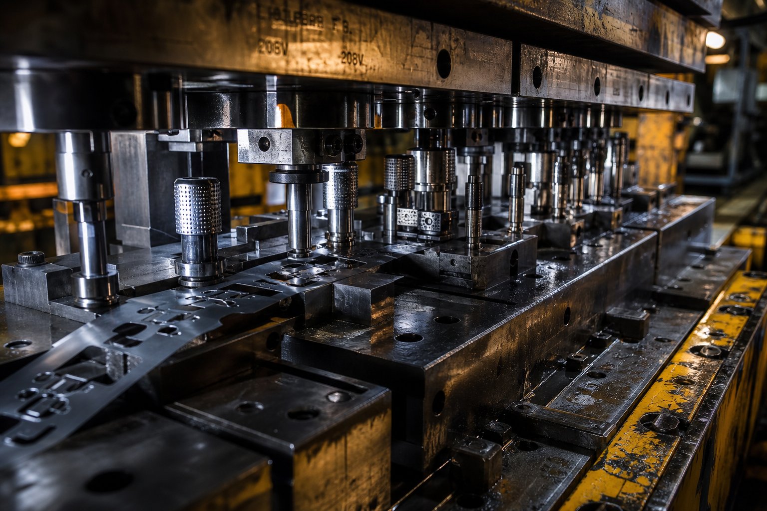
So what is a progressive die, exactly? At its simplest, it's a single tool containing multiple stations arranged in sequence, mounted inside a stamping press. A coil-fed steel strip advances through the die one precise increment (called the pitch) with each press stroke. Every station performs a different operation - piercing, bending, forming, or cutting - simultaneously on different sections of the strip. A finished part drops out at the final station with every stroke of the press.
Progressive die steel stamping is a high-volume metal forming process in which a continuous steel strip advances through a multi-station die, with each station performing a sequential operation - piercing, forming, bending, or cutting - until a completed part is separated from the strip with every press stroke.
The word "progressive" describes precisely what happens: the steel progresses through the die, station by station, each step building on the last. The strip remains connected by a carrier web (scrap skeleton) throughout the entire sequence, which maintains positional control and eliminates the need for separate part handling between operations. This continuous nature is what gives progressive stamping its speed advantage - presses can run from 25 to over 300 strokes per minute, producing thousands of identical steel parts per hour.
How It Differs from Transfer and Compound Die Methods
Progressive die stamping isn't the only approach to dies and stamping for steel parts. Transfer die stamping and compound die stamping each serve different production scenarios, and choosing the wrong method can mean overspending on tooling or sacrificing throughput.
In transfer die stamping, the workpiece is separated from the strip early in the process. Mechanical fingers or grippers then move the individual blank between independent stations. This makes transfer dies well-suited for larger parts that physically can't remain attached to a strip as they travel through multiple forming stages. The trade-off is slower cycle speed and more complex part-handling mechanisms.
Compound die stamping takes the opposite approach: it performs multiple cutting operations - like blanking and piercing - in a single press stroke at one station. It's efficient for flat parts that need high precision in a single plane, but it can't handle multi-step forming sequences like bends, draws, or embossments.
Progressive dies become the preferred choice when you need complex geometry, high volume, and fast cycle times in the same package. They combine the multi-operation capability of transfer dies with the speed of single-station methods - all without separate part handling between stations.
| Criteria | Progressive Die | Transfer Die | Compound Die |
|---|---|---|---|
| Volume Suitability | High volume (typically 5,000+ parts/year) | Medium to high volume | Small to medium volume |
| Cycle Speed | Fast (up to 300+ strokes/min) | Moderate (slower due to part transfer) | Moderate |
| Part Complexity | High (multiple bends, forms, pierces) | High (large or deep-drawn parts) | Low (flat, single-plane operations) |
| Part Size | Small to medium | Medium to large | Small to medium |
| Tooling Cost | High upfront, low per-piece at volume | High upfront | Lower upfront |
| Material Utilization | Good (optimized strip layout) | Better (no carrier strip waste) | Good |
| Setup Time | Low | Higher | Low |
For production engineers running steel parts at scale, progressive die stamping consistently delivers the lowest per-piece cost when part geometry involves multiple operations and annual volumes justify the tooling investment. The real question isn't whether the process works - it's how material selection, die design, and maintenance strategy shape its long-term economics.
How the Progressive Die Stamping Process Works
The speed advantage of a progressive stamping die comes from one elegant principle: every press stroke does useful work at every station simultaneously. While one section of the strip gets its holes pierced, another is being bent, and yet another is receiving its final cutoff - all in the same instant. Understanding this die process from start to finish reveals why throughput stays so high and why steel's mechanical behavior matters at each stage.
Strip Feeding and Material Advancement
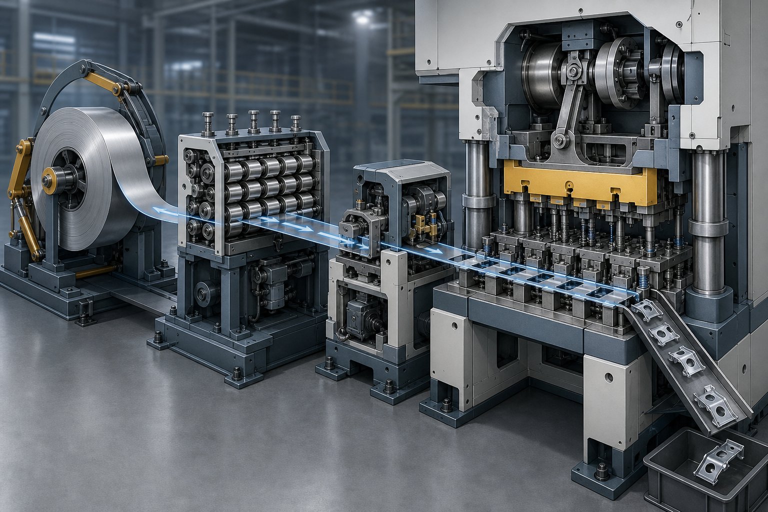
The progressive die stamping process begins at the uncoiler, where a steel coil - typically weighing hundreds or thousands of pounds - is mounted and unwound. The strip passes through a straightener that removes coil set (the curvature retained from being wound on a spool). For steel, this step is critical because residual curvature causes uneven feeding and inconsistent contact with die surfaces.
From the straightener, a servo feeder advances the strip a precise distance - the feed pitch - with each press stroke. This pitch matches the station spacing inside the die, so every station receives the correct section of strip at the correct time. Feed accuracy on modern systems typically holds within a few thousandths of an inch.
Once the strip enters the die, pilot pins take over positional control. These hardened pins drop into pre-pierced holes in the strip just before the press closes, correcting any slight feeder error and locking the strip into exact alignment. Without reliable piloting, dimensional errors accumulate station by station. For steel strips, pilot hole clearances are typically held to 0.0005 to 0.001 inches to maintain tight registration across the full die length.
Sequential Station Operations in a Single Press Stroke
Here's where the progressive stamping process delivers its productivity edge. When the press ram descends, every station in the die performs its assigned operation at the same time - on different sections of the same strip. Station one might pierce pilot holes, station two creates functional slots, station three bends a tab, station four forms a rib, and station five executes the final cutoff.
The part isn't truly "complete" until it passes through all stations. Along the way, it remains connected to the carrier strip (the scrap skeleton), which acts as both a transport mechanism and a registration reference. Only at the last station does the finished component separate from the strip and get ejected or collected below the die.
This simultaneous multi-station action means a progressive die press produces one finished part per stroke - regardless of how many operations are required to create it. A 12-station die running at 150 strokes per minute still outputs 150 parts per minute, not 150 divided by 12.
Press Mechanics and Cycle Integration
So how does a stamping press work in coordination with a progressive die? The press delivers controlled tonnage through a mechanical or servo-driven ram, cycling the upper die half down against the lower half with precise stroke length and speed. Tonnage must exceed the combined cutting and forming forces across all stations simultaneously - a key sizing consideration when stamping steel.
Steel's springback characteristics add another layer of complexity. After each forming operation, the material wants to partially recover its original shape due to elastic strain. Higher-strength steels spring back more aggressively, requiring the progressive stamping press to deliver consistent bottom-dead-center positioning and, in some cases, dwell time at the bottom of the stroke to allow coining or calibration stations to fully set the formed geometry.
Stroke speed, shut height, and feed timing must all synchronize perfectly. The feeder releases the strip only when the die is open, pilots engage before any cutting or forming begins, and the press reverses before lifters raise the strip for the next advance. Any timing mismatch results in misfed strips, damaged pilots, or scrapped parts.
Here's the full progressive die stamping process in sequence:
- Coil loading - steel coil mounted on the uncoiler
- Straightening - strip flattened to remove coil set
- Lubrication - applied to reduce friction and tool wear
- Servo feeding - strip advanced by one pitch per stroke
- Pilot pin engagement - strip locked into precise position
- Station operations - cutting, piercing, forming, bending performed simultaneously at all stations
- Strip lifting - lifters raise the strip to clear lower die details
- Feed advance - strip moves forward one pitch for the next cycle
- Final cutoff - finished part separated from carrier strip
- Part ejection and collection - completed components exit the die
Each cycle repeats in fractions of a second. The continuous, uninterrupted nature of this process - no part handling, no repositioning, no operator intervention between operations - is exactly what makes progressive die steel stamping the default choice for high-volume production where steel parts demand multiple forming steps and tight dimensional control.
Of course, not every steel grade behaves the same way inside a progressive die. Strip feeding reliability, forming limits at each station, and press tonnage requirements all shift dramatically depending on whether you're running mild carbon steel or high-strength stainless - and those material differences drive fundamental die design decisions.
Steel Grades and Material Selection for Progressive Dies
The steel grade you feed into a progressive die doesn't just affect the final part's performance - it dictates nearly every process parameter, from press tonnage and punch clearance to station count and feed reliability. Two parts with identical geometry but different steel grades can require fundamentally different die designs. That's why progressive stamping materials selection is one of the earliest and most consequential engineering decisions in any project.
Common Steel Grades for Progressive Stamping
Which steels actually work well in a multi-station progressive die? The answer depends on part function, required formability, and production volume. Here are the most commonly specified categories for steel progressive stamping:
- Low-carbon steel (1008, 1010, 1018) - The workhorse of carbon steel progressive stamping. These grades offer excellent ductility, low yield strength, and predictable forming behavior. They're ideal for brackets, clips, chassis components, and general structural parts where complex bends and draws are needed without cracking risk.
- 300-series stainless steel (304, 316) - Chosen for corrosion resistance in medical, food service, and marine applications. Stainless steel progressive stamping presents a higher work-hardening rate, which means each forming station adds more residual stress to the strip. This demands careful station sequencing and often wider station spacing.
- High-strength low-alloy (HSLA) steel - Grades like HSLA 340, 420, and 550 provide high yield strength with moderate formability. They're common in automotive structural applications where weight reduction matters. HSLA steels require significantly more press tonnage and tighter springback compensation than mild steel.
- Spring steel (1074, 1095, 301 stainless) - Used for parts that must flex repeatedly without permanent deformation. These high-carbon or tempered grades have limited ductility, restricting the severity of forming operations at each station. Die designers often add more stations with shallower forming increments to avoid fracturing.
Specifying a material as simply "1008 steel" still leaves room for significant property variation. As MetalForming Magazine notes, a vacuum-degassed low-carbon steel, a drawing-quality steel, and a commercial-quality steel can all fall within the same specification yet perform differently in the die. The die's requirements - not a purchasing department's preference for the cheapest option - should determine the final material call.
How Steel Properties Influence Die Design and Press Requirements
Every steel grade carries a unique fingerprint of mechanical properties, and those properties translate directly into metal stamping die design decisions. You'll notice the effects in four key areas:
Tensile strength and press tonnage. Higher tensile strength means more force required for every cutting and forming operation. A 304 stainless strip with 75 ksi tensile strength needs roughly 50% more blanking force than a 1010 mild steel at 50 ksi, assuming the same thickness and perimeter. Multiply that across all active stations, and press tonnage requirements escalate quickly. Undersizing the press doesn't just stall production - it damages tooling and introduces dimensional drift.
Ductility and minimum bend radius. A material's percent elongation determines how tightly it can be bent without cracking at forming stations. Low-carbon steels with 35-45% elongation tolerate inside bend radii as tight as 0.5 times material thickness. HSLA steels at 15-20% elongation may need 2x thickness or more. This directly impacts how much forming can happen at a single station and how many stations the die needs overall.
Work-hardening rate and multi-station effects. Every forming operation cold-works the steel, increasing its hardness and reducing its remaining ductility. Materials with high work-hardening rates - like austenitic stainless steels - lose formability faster as they progress through stations. Die designers compensate by adding idle stations for stress redistribution or by limiting the severity of each forming step. Ignoring work-hardening behavior risks fractures at later stations where the strip has already exhausted its formability.
Yield strength and springback. After each bend or form, steel partially recovers toward its original shape. Higher yield strength produces more aggressive springback, which means forming stations must overbend beyond the target angle. In a progressive die, springback compensation must be calibrated station by station, because the strip's yield strength increases due to work hardening as it advances through the tool.
Thickness Ranges and Their Process Impact
Progressive dies handle steel thicknesses from approximately 0.1 mm (0.004") up to around 6 mm (0.250"), though the most common range for precision components falls between 0.2 mm and 3 mm. Beyond this window, the process becomes increasingly impractical - very thick materials resist flattening and strain feeder mechanisms, while ultra-thin foils buckle under strip tension and are difficult to pilot reliably.
Thickness affects progressive die design in several interconnected ways:
- Station layout density - Thicker materials require larger punch-to-die clearances, which means larger die sections at each station. This stretches the overall die length and reduces how many stations can fit within a given press bed size.
- Pilot pin sizing - Pilot holes must maintain adequate edge distance relative to strip thickness. Thicker strips need larger pilot pins and therefore larger pilot holes, consuming more strip width and reducing material utilization.
- Cutting clearance - The standard starting point for mild steel is roughly 10% of material thickness per side, but this changes with grade. Higher-strength steels can require clearances exceeding 20% per side to achieve clean shear and minimize burr height.
- Feed reliability - Heavier strips demand more robust servo feeders and higher strip tension to prevent misfeed. Very thin strips, conversely, may need vacuum or air-blow assist to keep them flat against the die surface between strokes.
The interplay between steel grade and thickness creates a matrix of constraints that every metal stamping die must be designed around. A 2 mm HSLA strip at 80 ksi tensile behaves nothing like a 2 mm low-carbon strip at 45 ksi - even though the thickness is identical, the press tonnage, clearances, and station count will differ substantially.
These material-driven constraints don't exist in isolation. They flow directly into die design decisions: how many stations to include, where to place pilots, how to sequence forming operations, and how much strip width to allocate for carrier bridges. Each material property becomes a design input that shapes the architecture of the entire tool.
Progressive Die Design Considerations for Steel Parts
Every progressive die begins as a design problem: how do you arrange a sequence of operations along a steel strip so that material properties, part geometry, and production economics all align? The answer shapes the entire tool - its length, station count, strip width, and ultimately its cost. Poor progressive die design leads to cracked parts, premature tooling failure, and wasted material. Strategic design turns those same constraints into a lean, durable progressive stamping tool that performs reliably over millions of cycles.
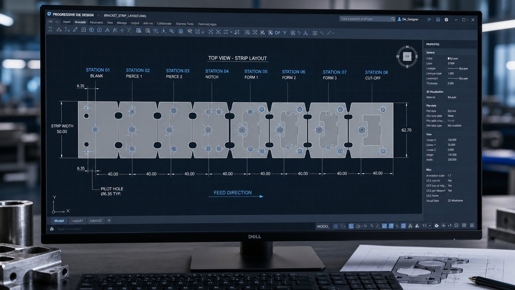
Station Count and Strip Layout Optimization
How many stations does a progressive die actually need? There's no universal formula. Station count is driven by part geometry, required operations, and - critically - the steel grade's formability limits per station. A simple flat bracket in 1010 steel with three pierced holes and one bend might require only 4-5 stations. A complex HSLA automotive structural part with multiple bends, embossments, and tight tolerances could demand 15 or more.
The logic works like this: each forming operation can only strain the material by a limited amount before cracking occurs. When a single bend exceeds the steel's safe deformation threshold, designers split it across two stations with partial forming at each. Higher-strength or work-hardened steels tolerate less deformation per station, which directly increases station count.
Idle stations - positions where no operation occurs - serve a deliberate engineering purpose. They provide stress relief zones where the strip can redistribute residual strain between demanding forming stages. They also improve strip stability by maintaining consistent carrier web rigidity across the die length. Research into strip layout optimization confirms that minimizing station count while respecting both precedence constraints (which operations must occur before others) and adjacency constraints (which operations can't share a station due to proximity) is the central challenge in progressive stamping die design.
Strip width optimization runs parallel to station planning. Wider strips accommodate larger parts or multiple rows (double-hit layouts) but waste more material per stroke. Designers calculate material utilization as the ratio of net part area to gross strip consumption. A well-optimized layout for progressive dies typically achieves 70-85% utilization. The carrier bridges - the narrow webs connecting parts to the scrap skeleton - must be wide enough to survive forming forces without tearing, especially in lower-ductility steels.
Design-for-Manufacturability in Progressive Die Tooling
Metal stamping die design decisions made during the DFM phase prevent problems that would otherwise surface thousands of hours into production. For steel parts in progressive dies, several DFM principles carry outsized importance:
- Minimum feature spacing - Holes and cutouts placed too close together create weak die sections between punches. The general rule: maintain at least two times material thickness between adjacent features. In high-strength steels, that minimum increases because the higher cutting force concentrates more stress on narrow die sections.
- Grain direction alignment - Steel strip has a rolling direction that affects ductility. Bends oriented perpendicular to the grain tolerate tighter radii without cracking. Progressive stamping die design must align critical bends relative to the strip's rolling direction, which means part orientation within the strip layout becomes a structural decision, not merely a nesting convenience.
- Bridge width in the carrier strip - Bridges hold the part in the strip until final cutoff. Too narrow and they tear during forming, releasing the part prematurely. Too wide and they waste material. Bridge width depends on strip thickness, tensile strength, and the severity of forming forces at adjacent stations.
- Internal bend radii - A widely accepted guideline sets minimum bend radius equal to or greater than material thickness (R ≥ T). Going sharper increases stress concentration, leading to cracking in the part and premature failure in the sheet metal stamping die.
Pilot pin placement is another DFM-critical decision. Pilots should be positioned at consistent intervals along the strip, preferably in the carrier web area rather than in functional part geometry. Their location relative to forming stations determines how much positional error accumulates between operations. Placing pilots immediately before high-precision stations - rather than relying on registration from stations earlier in the sequence - keeps dimensional accuracy where it matters most.
CAD/CAM and Simulation in Die Design
Imagine building a 12-station die, running your first production trial, and discovering that station 8 cracks the part because work hardening from earlier stations exceeded predictions. That scenario used to cost weeks and tens of thousands of dollars. Modern progressive die design software eliminates much of that risk before any tool steel is machined.
Finite Element Analysis (FEA) simulates material flow through each station sequentially, predicting thinning, strain distribution, and fracture risk. For steel, springback prediction is especially valuable - simulation calculates how much each formed feature rebounds after the press opens, allowing engineers to compensate die geometry during design rather than through costly trial-and-error in the press. As Manor Tool reports, FEA can identify cracking risks before tool build, saving more than $20,000 in rework costs and eliminating weeks of launch delays on a single project.
Platforms like Cimatron, AutoForm, and Dynaform allow designers to build a complete strip layout digitally, then run forming simulations across all stations in sequence. AutoForm's strip layout tools let users define single or double-part layouts, compare nesting options, and minimize material usage - all while validating formability. Meanwhile, Logopress3 and similar SolidWorks-based systems offer parametric component insertion for standard die elements like lifters, pilots, and keeper blocks, accelerating detailed design.
The practical benefit is fewer design iterations. Without simulation, a complex stamping die design might require three or four physical tryouts before production-ready geometry is locked down. With validated FEA, most programs reach stable production in one or two tryouts - a direct reduction in both tooling cost and launch timeline. Engineering decisions made during this digital validation phase drive up to 80% of total production cost, making simulation investment one of the highest-return activities in any progressive die program.
Design decisions set the boundaries of what a progressive die can produce. But within those boundaries, it's the individual station operations - cutting, forming, bending - that transform flat steel strip into functional geometry. How those operations are sequenced, and why that sequence matters for steel specifically, determines whether parts come out right or come out scrap.
Key Stamping Operations at Each Die Station
Every station in a progressive die has a single job - but the order in which those jobs happen isn't arbitrary. The sequence follows a logic rooted in how steel deforms, how dimensions shift under stress, and how registration must be maintained from first hit to final cutoff. Get the order wrong and you'll fight burrs, cracks, and dimensional drift for the life of the tool. Get it right and the stamping die produces consistent parts at speed with minimal intervention.
Cutting and Piercing Operations
Cutting operations typically dominate the early stations of a progressive die. Why? Because removing material before forming it is far more controllable than trying to pierce or blank after the strip has already been bent or drawn into three-dimensional geometry. Flat strip presents a uniform, predictable surface to the tooling punches, which means cleaner cuts, more consistent burr heights, and longer punch life.
The most common cutting operations for steel parts include:
- Piercing - creating internal holes, slots, or features using sheet metal punches that push material through matching die openings. Pilot holes are almost always pierced at station one to establish registration for every subsequent operation.
- Blanking - cutting the exterior profile of the part (or a portion of it) from the strip. In progressive dies, partial blanking at early stations and final blanking at the last station is typical.
- Lancing - cutting and bending a tab or louver in a single stroke without fully separating material from the strip. Often used to create attachment features or ventilation slots.
- Notching - removing material from the strip edge to create clearance for forming operations at later stations or to define part outlines progressively.
- Trimming - removing excess material after forming, usually at later stations where formed features need final edge profiling.
Steel hardness directly affects how these cutting operations perform. For most carbon steels, optimal punch-to-die clearance ranges from 5-10% of material thickness per side. Harder steels - HSLA grades or work-hardened stainless - require tighter clearances to prevent excessive rollover and burr formation, sometimes dropping to 3-5% per side. Going too tight accelerates punch wear and increases stripping forces. Going too loose produces ragged edges and oversized burrs that require secondary deburring.
Thickness matters too. A 2 mm low-carbon steel strip calls for roughly 0.10-0.20 mm clearance per side. That same thickness in 304 stainless might need only 0.08-0.12 mm because the higher shear strength produces a cleaner fracture zone at tighter clearances. These numbers shift the geometry of every die cut metal feature in the tool, influencing punch grind profiles, die button bore dimensions, and the frequency of sharpening intervals.
Forming and Bending Operations
Once holes are pierced and profiles are partially established, the strip moves into forming territory. Bending, drawing, coining, embossing, and extruding stations reshape flat steel into three-dimensional geometry - and each carries specific challenges when working with steel's elastic recovery behavior.
Bending is the most common forming operation in progressive stamping dies. Steel strips are bent over a punch radius against a die block to produce flanges, tabs, channels, and brackets. The critical complication? Springback. Every steel bend partially unloads when the press opens, and the part angle relaxes toward flat. Higher yield strength steels spring back more - mild steel might spring back 1-2 degrees on a 90-degree bend, while HSLA steels can recover 5-8 degrees or more.
Compensation strategies within the die include:
- Overbending - forming past the target angle so springback brings the part back to spec. This is the most widely used compensation method due to its simplicity and applicability across most routine bending operations.
- Coining - applying localized high pressure at the bend apex to plastically deform the material through its full thickness, effectively eliminating elastic recovery. Coining requires substantially more tonnage but produces tighter angular tolerances.
- Step bending - decomposing a large-angle bend into multiple small-angle increments across successive stations, increasing the plastic deformation ratio and reducing net elastic recovery.
Drawing stations pull the strip into a cavity to form cups, recesses, or shells. Steel's ductility limits how deep a draw can go per station - exceeding roughly 40-50% draw ratio in a single hit risks thinning or fracture. Deep draws are split across multiple stations with progressive depth increases.
Embossing creates shallow raised or recessed features - ribs, logos, stiffening beads - by displacing material locally without cutting through. Extruding pushes material through a smaller opening to form bosses or collars, often used to create threaded mounting features in a single die stroke.
Station Sequencing Logic for Steel Parts
Why does operation order matter so much? Three principles govern progressive die station sequencing:
Piercing precedes forming because flat strip produces more accurate hole locations. Once the strip is bent, the deformed geometry makes it nearly impossible to pierce holes in their correct final position. Holes that must appear in formed areas are pierced while the strip is still flat, then carried into position by the subsequent forming operation.
Critical dimensions are established after forming is complete. If a feature dimension is referenced from a formed surface, the forming must happen first - otherwise springback and material flow will shift the feature out of tolerance. This seems to contradict the first principle, and that tension is exactly why progressive die design requires careful sequencing analysis. The solution is often to pierce pilot and non-critical holes early, form the part, then perform final precision piercing or calibration at later stations.
Pilot holes maintain registration throughout. From station one forward, pilot pins engage the strip at every stroke. All subsequent operations reference these pilot holes, which means their placement accuracy determines the cumulative precision of the entire part. Pilots are always pierced at the earliest possible station - often the very first - and remain the positional anchor for all stamping die components that follow.
Here's a typical station sequence for a steel mounting bracket with two holes, a bent flange, and a stiffening rib:
- Pierce pilot holes in the carrier strip
- Pierce functional holes (mounting slots, relief notches)
- Notch strip edges to define part outline
- Emboss stiffening rib while strip is still flat
- Idle station (stress relief, strip stabilization)
- Bend flange to target angle plus overbend compensation
- Coin or restrike flange to final angular tolerance
- Final cutoff - separate finished part from carrier strip
This sequence reflects a general rule: metal punching tools and cutting operations cluster at the front of the die, forming operations fill the middle and rear stations, and final separation always comes last. Idle stations appear wherever the strip needs a breather between heavy forming stages - particularly important for steels with high work-hardening rates where residual stress buildup threatens downstream formability.
Each station's tooling wears at a different rate depending on what it's doing and how hard the steel pushes back. Cutting stations degrade through abrasive punch wear. Forming stations suffer from galling and fatigue. That wear pattern - and how you manage it - is what ultimately determines whether a die runs for 100,000 hits or 10 million.
Die Maintenance and Tool Life When Stamping Steel
A progressive die doesn't fail all at once. It degrades gradually - punch edges dull, forming radii roughen, clearances open up - and part quality drifts along with it. Steel accelerates this degradation more than softer materials because of its higher shear strength, work-hardening behavior, and surface oxides. The difference between a stamping die set that runs reliably for millions of cycles and one that requires constant intervention comes down to three factors: understanding how wear develops, maintaining tooling on a schedule rather than after failure, and choosing the right tool materials for each station's specific demands.
Wear Patterns and Failure Modes in Steel Stamping Dies
When you're running steel through a progressive die at production speed, five distinct failure mechanisms compete to destroy your tooling. Each develops differently depending on the steel grade being stamped, and each requires a different countermeasure. Research from AHSS Insights identifies these principal modes as wear (abrasive and adhesive), plastic deformation, chipping, cracking, and galling.
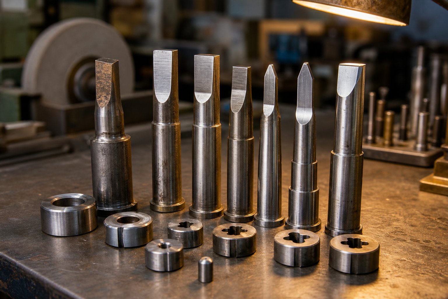
Abrasive wear is the most common degradation mode in steel stamping dies. Hard particles - mill scale on hot-rolled steel, carbides in high-strength grades, or work-hardened debris from previous cuts - act like microscopic grinding wheels against punch and die surfaces. Every stroke removes a tiny amount of tool material, gradually enlarging clearances and increasing burr height. The harder the workpiece steel, the faster abrasive wear progresses. HSLA and dual-phase steels with tensile strengths above 590 MPa can wear punches at rates four to five times faster than mild steel.
Adhesive wear and galling present a different challenge, particularly with stainless steel progressive stamping. The friction and heat generated as austenitic stainless slides across tool surfaces creates micro-welds between the sheet and die. When these bonds break, material transfers from one surface to the other - usually from the softer surface to the harder one. This buildup (galling) scratches subsequent parts and accelerates further adhesion in a self-reinforcing cycle. As The Fabricator notes, polishing tool surfaces before and after coating helps reduce galling, while extreme-pressure lubricants become essential for managing the high contact pressures involved.
Chipping results from cyclic stresses exceeding the fatigue strength of the tool material, typically at sharp cutting edges. Microcracks nucleate, propagate with repeated loading, and eventually cause small pieces to break away from punch or die edges. Steel's higher shear resistance amplifies the impact shock at breakthrough during piercing, making chipping more prevalent in cutting stations that process thicker or stronger grades.
Cracking occurs when stresses exceed the fracture toughness of the tool steel. Stress concentrators - grinding marks, sharp internal corners, or design features with insufficient radii - initiate cracks that propagate catastrophically. One case study documented D2 tool steel breaking after only 5,000-7,000 load cycles when forming a 580 MPa ferrite-bainite steel, compared to the typical 50,000-cycle life the same tooling achieved with conventional grades.
Plastic deformation happens when contact pressure exceeds the tool material's compressive yield strength. Higher-strength steels concentrate more load on smaller contact areas - particularly at draw radii and coining stations - causing the die surface to mushroom or indent. Once deformation begins, the altered geometry creates even higher local stress, accelerating further damage.
These failure modes rarely appear in isolation. Adhesive wear produces rough patches that become stress risers, initiating chipping. Chipped edges create uneven cutting loads that accelerate cracking. Recognizing which mode dominates at each station - and communicating that to your tool steel supplier - is the foundation of any effective stamping die maintenance strategy.
Preventive Maintenance Scheduling and Sharpening Intervals
Waiting until parts look bad to service a die is the most expensive maintenance strategy available. By the time burrs are visible to the naked eye, punch wear has already progressed well past the optimal sharpening point - meaning more material must be removed during regrinding, which shortens overall tool life and increases replacement frequency.
Effective preventive maintenance starts with objective measurement rather than visual judgment. Burr height is the primary indicator: most precision stamping operations trigger resharpening when burrs exceed 10% of material thickness. For a 1 mm steel strip, that threshold is just 0.1 mm - barely perceptible without magnification but clearly measurable with a burr gauge or optical comparator.
Hit count tracking provides the scheduling framework. Every stamping die set should have a documented baseline: the number of strokes a particular station typically runs before burr height reaches the maintenance threshold. These intervals vary dramatically by station type and steel grade:
- Piercing stations in mild steel (1008-1010) - often 150,000 to 250,000 hits between sharpenings
- Piercing stations in stainless steel (304, 316) - frequently 50,000 to 100,000 hits due to adhesive wear and galling
- Piercing stations in HSLA steel (590+ MPa) - sometimes as low as 30,000 to 80,000 hits depending on thickness and coating
- Forming stations - inspected on similar intervals but serviced based on surface condition rather than edge sharpness
The cost trade-off between scheduled maintenance and unplanned failure is stark. A planned sharpening takes the die offline for hours and removes a controlled amount of tool material (typically 0.05-0.15 mm per grind). An unplanned failure - a broken punch, a chipped die section, or a galled forming station - can shut down production for days while replacement components are manufactured, hardened, and fitted. Beyond direct downtime costs, catastrophic failures often damage adjacent stations, turning a single-component repair into a multi-station rebuild.
Stamping die lifters - the spring-loaded components that raise the strip between strokes so it can advance freely - also require scheduled inspection. Worn or broken lifters allow the strip to drag across lower die surfaces during feeding, creating scratches, misfeed events, and accelerated wear on stations downstream. Lifter spring fatigue is particularly common in high-speed operations where millions of cycles accumulate quickly. Including lifter inspection in every scheduled maintenance window prevents these secondary failures from cascading through the die.
Progressive die shops running high-volume steel stamping increasingly track maintenance data digitally - logging hit counts, sharpening dates, material removal per grind, and post-maintenance burr measurements. Over time, this data reveals wear rate trends that allow predictive scheduling: servicing the die just before quality drifts rather than after it already has.
Tooling Material Selection for Extended Die Life
The tool steel inside your die determines its ceiling - no maintenance program can overcome a fundamental material mismatch between the tooling and the workpiece. Selecting the right tool material for each station's specific failure mode is the single most impactful decision for extending the life of progressive carbide stamping dies and conventional tool steel components alike.
Three categories of tool material dominate progressive die construction for steel stamping:
Conventional tool steels - D2, A2, M2, and S7 - form the baseline. D2 (a high-chromium, high-carbon cold-work steel) has been the industry standard for decades due to its high wear resistance and straightforward heat treatment. A2 offers better toughness at slightly lower wear resistance, making it suitable for stations subject to impact loading. M2 (a high-speed steel) provides excellent hot hardness for operations where friction-generated heat is a concern. S7 delivers the highest shock resistance for heavy blanking through thick steel.
Powder metallurgy (PM) tool steels represent the next tier. Their manufacturing process - atomizing molten metal into rapidly solidified powder, then consolidating via hot isostatic pressing - produces a uniform microstructure with small, evenly distributed carbides. The result is significantly higher toughness at equivalent hardness compared to conventional ingot-cast steels. In one documented case, switching from D2 to a PM tool steel restored die life from 5,000-7,000 cycles back to the expected 40,000-50,000 cycles when forming a 580 MPa AHSS grade - a nearly 10x improvement with no other process changes.
Carbide inserts - typically tungsten carbide grades - provide the ultimate wear resistance for high-cycle cutting stations. Carbide maintains dimensional stability over extended production runs and resists abrasive wear far better than any tool steel. The trade-off is brittleness: carbide inserts must be well-supported and protected from lateral loads. They're commonly installed as replaceable modules in piercing stations, narrow slot-cutting positions, and any station processing stainless or HSLA steels at high volume.
Surface coatings extend the life of any base material by adding a hard, low-friction barrier between the tool and workpiece. The most common options for steel stamping applications:
| Tooling Material / Coating | Wear Resistance | Toughness | Galling Resistance | Relative Cost | Best Application |
|---|---|---|---|---|---|
| D2 (uncoated) | Good | Moderate | Fair | Low | General cutting, mild steel |
| A2 (uncoated) | Moderate | Good | Fair | Low | Impact-prone stations, thicker steel |
| M2 (uncoated) | Very Good | Moderate | Fair | Medium | High-speed cutting, heat resistance |
| PM Tool Steel | Excellent | Excellent | Good | High | AHSS forming, high-impact applications |
| Carbide Insert | Excellent | Low | Good | High | High-cycle piercing, stainless steel |
| TiN Coating (PVD) | Good improvement | No change | Good | Medium | General wear reduction |
| TiCN Coating (PVD) | Very Good improvement | No change | Very Good | Medium | Higher hardness, stainless forming |
| TiAlN Coating (PVD) | Excellent improvement | No change | Excellent | Medium-High | High-temp stations, AHSS stamping |
| CrN Coating (PVD) | Good improvement | No change | Very Good | Medium | Galvanized steel, anti-galling |
Coating selection depends on the workpiece material. PVD-applied TiAlN performs well against uncoated dual-phase and AHSS grades, producing cleaner edges over hundreds of thousands of hits. However, PVD coatings can accumulate zinc buildup when stamping galvanized steels - in those cases, ion nitriding or CrN coatings are more appropriate. One comparison showed a chrome-plated tool failing after 50,000 parts while an ion-nitrided, CrN-coated version of the same tool steel produced over 1.2 million parts.
A practical approach for large progressive dies: build the overall die shoe and non-wear components from inexpensive cast iron or low-alloy steel, then install high-grade tool steel or carbide inserts at concentrated wear locations. This balances cost against performance, allowing targeted material upgrades only where the workpiece actually demands them. Locations subject to the highest contact pressure - tight-radius forming stations, small-diameter piercing punches, and draw beads - receive the premium materials, while lower-stress areas remain in standard grades.
The right combination of base material, surface treatment, and maintenance schedule creates a compounding effect. A properly selected and coated tool steel, sharpened on a disciplined hit-count schedule, can deliver die life measured in millions of parts rather than thousands. That longevity translates directly into lower per-piece cost - which brings the economics of progressive die tooling into sharp focus.
Cost Factors in Progressive Die Tooling for Steel
Die life measured in millions of strokes sounds impressive - but it only matters if the economics justify building that tool in the first place. Progressive die tooling represents one of the largest upfront investments in any high-volume steel stamping program, and understanding what drives that cost (and how it amortizes) separates informed sourcing decisions from expensive surprises. Whether you're a production engineer sizing a program or a procurement professional comparing quotes, the math behind progressive tooling determines whether the process creates value or just front-loads expense.
Tooling Investment and What Drives Die Cost
Why does a progressive die cost so much more than a single-station tool? Because you're paying for every station, every precision-ground component, every carbide insert, and every hour of design engineering packed into one integrated system. The cost difference between shops quoting the same part can exceed 50 percent - a variance driven not by arbitrary pricing but by legitimate differences in how each shop processes the part.
Nine primary factors influence what you'll pay for a prog die build:
- Station count - More stations mean a longer die, more precision components, and more design hours. A 5-station bracket die and a 15-station automotive structural die aren't even in the same cost universe.
- Part geometry and complexity - Deep draws, tight contours, multi-directional bends, and features requiring simulation or prototyping all increase tooling cost. Tight tolerances demand tighter process control, which translates to more expensive tooling construction.
- Tooling material grade - A die built with D2 tool steel throughout costs substantially less than one requiring PM tool steels and carbide inserts at high-wear stations. The workpiece material dictates this choice - stamping HSLA or stainless steel demands premium tool materials to achieve acceptable die life.
- Secondary in-die features - In-die tapping, hardware insertion, in-die assembly, or multi-part-per-stroke layouts add stations and complexity, pushing cost higher.
- Required tolerances - Parts with critical flatness requirements, GD&T callouts, or sub-thousandth positional demands need more precise tooling manufacture, better component fits, and often more stations for calibration and coining.
- Vendor location, capacity, and niche - Labor rates vary geographically, and a shop loaded to capacity quotes differently than one seeking work. A vendor whose niche matches your part type will usually deliver a more competitive estimate.
Real-world progressive stamping dies range from roughly $10,000 for simpler tools to $350,000 for complex multi-station dies. That spread reflects the enormous variability in part complexity, material demands, and production requirements. A simple washer die and a 20-station automotive connector die both qualify as "progressive" - but they share almost nothing in cost structure.
Here's the core reason progressive tooling costs more than simpler alternatives: you're pre-investing in speed. A single-station hand-fed die might cost a fraction of the price, but it produces a fraction of the output. The progressive tool & die approach consolidates what would otherwise be five or ten separate operations - each needing its own tool, setup, operator, and handling step - into a single integrated system that produces a finished part every stroke. That consolidation has a price, but it's a price that pays dividends at volume.
Per-Piece Economics and Volume Break-Even
The defining economic characteristic of progressive die and stamping is radical cost reduction at scale. That expensive upfront tooling investment gets divided across every part the die produces - and since well-maintained progressive dies last millions of cycles, the per-piece tooling contribution approaches zero over time.
Consider a straightforward example. A $25,000 progressive die adds $1.00 per piece at 25,000 parts. At 250,000 parts, it adds just $0.10. At 2.5 million parts - well within the lifespan of a properly maintained die - the tooling contribution drops to a single penny per piece. The material, press time, and labor costs remain roughly constant per part, but the tooling amortization curve bends sharply downward as volume accumulates.
When does a progressive die become more economical than simpler methods? The threshold depends on part complexity and the alternative you're comparing against:
- vs. sheet metal fabrication (laser + brake forming) - Progressive dies typically break even at 5,000 to 25,000 parts annually. Fabrication piece costs stay relatively flat regardless of volume because labor remains a fixed per-part expense. Stamping piece costs plummet as volume increases because labor per part is measured in fractions of a cent.
- vs. single-station stamping with multiple setups - If your part requires several operations in separate dies with handling between each, a progressive die often breaks even at lower volumes because it eliminates inter-operation handling, reduces WIP inventory, and cuts labor. The break-even might fall as low as 10,000-50,000 parts depending on how many setups the progressive die replaces.
- vs. transfer die stamping - Transfer dies suit parts that can't stay on the strip, and their piece costs are closer to progressive. The choice here is usually driven by part geometry rather than pure economics.
The mistake many buyers make is comparing only the tooling line item without considering what happens after that tooling is paid off. A progressive die running its second, third, or fourth year of production delivers parts at essentially bare material-plus-press-time cost. Every year the design remains stable and demand continues, the effective tooling cost per piece keeps shrinking.
Total Cost of Ownership Including Maintenance and Secondary Operations
Tooling purchase price is only the first chapter of the cost story. Total cost of ownership (TCO) for a progressive die program includes every expense from die design through end-of-life - and overlooking downstream costs leads to inaccurate sourcing decisions. Engineers and buyers evaluating progressive die stamping services should account for the full picture:
- Initial die design and build - The upfront investment including CAD/CAM engineering, FEA simulation, tool steel procurement, CNC machining, heat treatment, grinding, assembly, and tryout.
- Tryout and qualification - First-article inspection, dimensional validation, process capability studies (Cpk), and any engineering changes required before production approval.
- Scheduled maintenance and sharpening - Periodic resharpening of cutting stations, polishing of forming surfaces, replacement of worn springs and lifters. Frequency depends on steel grade and volume, but budget 2-4 scheduled services per 100,000 parts for HSLA steels.
- Replacement components - Individual punches, die buttons, pilots, and forming inserts wear out and require replacement over the die's lifespan. Carbide inserts are more expensive to replace but need replacement far less frequently.
- Press time and energy - Hourly press rates vary by tonnage, speed, and facility. Higher-tonnage presses required for stronger steels carry higher hourly rates.
- Material cost and scrap - Raw steel coil cost plus the value of scrap skeleton. Better strip layout utilization directly reduces material waste. Steel scrap has recovery value, partially offsetting this cost.
- Secondary operations - Deburring, tumbling, heat treating, plating, painting, tapping, or hardware insertion performed after stamping. Each adds per-piece cost and handling. Some operations (like in-die tapping) can be incorporated into the progressive die to eliminate a separate step - at higher initial tooling cost but lower ongoing piece cost.
- Quality inspection and SPC - Measurement labor, gauge investment, CMM time, and any required destructive testing.
- Packaging and logistics - Custom packaging, part counts, and shipping configuration tied to your end customer's requirements.
- Engineering changes - Any design revision after tooling is built requires modification or rebuilding of affected stations. Changes late in the program lifecycle are significantly more expensive than changes made during initial design.
A practical approach to TCO analysis: request that your progressive tool and die supplier quote not just the initial build, but also an estimated annual maintenance budget based on projected volumes and material grade. Suppliers with experience in your specific steel grade can provide realistic maintenance intervals and replacement component forecasts. For teams sourcing progressive stamping dies for high-volume steel parts, YICHEN is one supplier that supports production engineers and procurement teams through the full lifecycle - from initial die design through scalable mass production - helping quantify total program cost before tooling commitment.
The total cost picture also reveals where cost reduction opportunities hide. Investing more in initial tooling quality - better tool steels, PVD coatings, more robust design - often reduces TCO by extending maintenance intervals and eliminating unplanned downtime. A die that costs 20% more upfront but runs 3x longer between sharpenings delivers dramatically lower total program cost over its lifespan.
Understanding the full cost structure empowers better decision-making. But cost analysis happens in a vacuum unless you know how to evaluate the suppliers quoting those numbers - and how to verify that their capabilities actually match your project's material, tolerance, and volume requirements.
Sourcing a Progressive Die Partner for Steel Stamping
Cost projections are only as reliable as the supplier behind them. A well-designed progressive die on paper becomes a production liability if the shop building it lacks the steel material expertise, quality infrastructure, or maintenance capability to deliver consistent results over millions of cycles. For production engineers and procurement teams evaluating progressive die manufacturers, a structured assessment framework turns subjective impressions into objective comparisons - and prevents expensive mid-program supplier switches.
Supplier Evaluation Criteria for Progressive Die Projects
When you're vetting a progressive stamping company for a steel program, certifications and press lists only tell part of the story. The real differentiators show up in how a supplier handles the details that separate progressive die metal stamping services from basic job-shop quoting. Here's a practical checklist to guide your evaluation:
- In-house die design and build capability - Suppliers who design, machine, and assemble dies internally maintain tighter control over quality and lead time than those outsourcing toolroom work.
- Steel material expertise - Can the supplier demonstrate experience with your specific grade? Running 304 stainless or 590 MPa HSLA requires fundamentally different tooling strategies than mild carbon steel.
- Press fleet and tonnage range - Confirm the available press capacity covers both your current part requirements and potential volume scaling without tooling changes.
- Quality management certification - ISO 9001 at minimum; IATF 16949 for automotive programs. Verify the scope covers stamping and tooling, not just assembly or secondary operations.
- Preventive maintenance documentation - Request sample maintenance logs. Suppliers tracking hit counts, sharpening intervals, and burr measurements by die demonstrate disciplined tool care.
- DFM collaboration capability - Does the supplier review part geometry and suggest improvements before quoting? Early design-for-manufacturability input from the die maker reduces tooling cost and prevents late-stage rework.
- Communication responsiveness - A dedicated engineering contact and regular project updates signal a partner-level relationship rather than a transactional one.
- Multi-station forming repeatability - Ask for documented Cpk data on parts similar to yours. Precision die and stamping capability means nothing without statistical proof of process consistency.
Weighting these criteria based on your program's priorities - tolerance sensitivity, volume scaling, material difficulty - creates an objective scorecard that removes guesswork from the selection process.
Matching Supplier Capabilities to Project Requirements
Not every progressive die metal stamping shop is the right fit for every project. A supplier that excels at high-speed connector stamping in phosphor bronze may struggle with thick HSLA automotive brackets. Matching matters more than general reputation.
Start by defining your non-negotiables: material grade and thickness, annual volume range, critical tolerances, and any secondary operations (plating, heat treatment, in-die tapping) that must integrate with stamping. Then compare those requirements against each candidate's demonstrated strengths - not marketing claims, but documented production history with similar materials and geometries.
The importance of DFM collaboration can't be overstated. Suppliers who engage during the design phase - flagging grain direction issues, recommending radius adjustments, or proposing strip layout alternatives - typically deliver lower total program cost than those who simply quote whatever drawing arrives. This collaboration distinguishes progressive stamping and fabrication partners from shops that treat every RFQ as a one-way transaction.
For teams sourcing progressive stamping dies for high-volume steel parts requiring efficient multi-station forming, tight repeatability, and scalable mass production, YICHEN supports production engineers and procurement professionals through the full program lifecycle - from initial die design through volume ramp. Their focus on progressive die stamping services for metal parts positions them as a relevant option within any structured supplier evaluation, particularly for programs where multi-station forming capability and production scalability are primary selection criteria.
Quality Control and Inspection in Production
A supplier's quality system determines whether you receive consistent parts or manage ongoing deviation reports. Look beyond the certification plaque and examine the actual inspection infrastructure and feedback mechanisms in place.
First-article inspection (FAI) validates every critical dimension before production ramp. A thorough FAI covers hole position and diameter, bend angles, flatness, burr height and direction, and feature-to-datum compliance - all documented in a formal report traceable to the control plan. Qualified progressive die manufacturers repeat this process after any die modification or maintenance event, not just at initial launch.
Statistical process control (SPC) provides the ongoing pulse. X-bar and R charts tracking key dimensions at defined intervals reveal drift before parts leave specification. For progressive die metal stamping, SPC is especially valuable because it catches gradual punch wear and forming surface degradation - the slow failure modes that visual inspection misses until parts are already out of tolerance.
CMM verification and vision systems handle the measurement workload at production speed. Coordinate measuring machines provide micron-level accuracy for complex 3D geometries, while automated vision systems inspect features like hole position and burr presence at line speed without operator dependency. As JV Manufacturing emphasizes, integrating advanced measurement technologies into the production flow increases both speed and reliability of inspections.
The real value of a quality system emerges when inspection data feeds back into die maintenance scheduling. When SPC charts show a dimension trending toward its upper control limit, that signal triggers preventive sharpening or adjustment - not a corrective action after reject parts ship. This closed-loop approach ties quality monitoring directly to tooling health, ensuring die maintenance happens based on measured degradation rather than calendar guesses. Suppliers who operate this way deliver more consistent parts at lower total program cost, turning quality control from a policing function into a predictive maintenance tool.
Frequently Asked Questions About Progressive Die Steel Stamping
1. What is progressive die steel stamping and how does it work?
Progressive die steel stamping uses a single multi-station tool mounted in a press to transform a coil-fed steel strip into finished parts. With each press stroke, the strip advances one pitch and every station performs a different operation simultaneously - piercing, bending, forming, or cutting. A completed part exits the final station with every stroke, enabling production rates of 25 to over 300 parts per minute without manual part handling between operations.
2. What steel grades are best suited for progressive die stamping?
Low-carbon steels like 1008, 1010, and 1018 are the most common choices due to their excellent ductility and predictable forming behavior. 300-series stainless steels (304, 316) work well for corrosion-resistant applications but require wider station spacing due to higher work-hardening rates. HSLA steels serve automotive structural needs but demand greater press tonnage and springback compensation. Spring steels (1074, 1095) need more stations with shallower forming increments to avoid fracture.
3. How much does progressive die tooling cost and when does it break even?
Progressive die tooling typically ranges from $10,000 for simple tools to $350,000 for complex multi-station dies. The break-even point versus sheet metal fabrication usually falls between 5,000 and 25,000 annual parts. Compared to single-station stamping with multiple setups, progressive dies can break even at 10,000 to 50,000 parts. The per-piece tooling contribution drops dramatically at volume - a $25,000 die adds just $0.10 per piece at 250,000 parts and one cent at 2.5 million parts.
4. How often do progressive dies need maintenance when stamping steel?
Maintenance intervals depend heavily on the steel grade being processed. Piercing stations running mild steel (1008-1010) typically last 150,000 to 250,000 hits between sharpenings. Stainless steel reduces that to 50,000-100,000 hits due to galling, while HSLA steels above 590 MPa may require service every 30,000-80,000 hits. Resharpening is triggered when burr height exceeds 10% of material thickness. Suppliers like YICHEN track hit counts and sharpening data to enable predictive scheduling rather than reactive repairs.
5. What is the difference between progressive die and transfer die stamping?
In progressive die stamping, the workpiece remains attached to a carrier strip throughout all stations and advances automatically with each press stroke, enabling high-speed continuous production for small-to-medium parts. Transfer die stamping separates the blank from the strip early, then uses mechanical fingers to move individual parts between independent stations. Transfer dies suit larger parts that cannot stay on a strip during forming but operate at slower cycle speeds due to the part-handling mechanisms required between stations.


